

Presentation to the RASRS
Standpipe LAPS Upgrade 2020PacifiCorp
July 30-31, 2019

Transmission PlanningRikin Shah

3
Current LAPS Logic• The Standpipe RAS remains a Local Area
Protection Scheme (LAPS) as accepted by RASRS in 2014.
• The loss of Standpipe – Platte 230 kV line forces all the generation (~ 475 MW) in the area to go through Dave Johnston area causing low voltages in the Spence/ Badwater area.
• The Standpipe LAPS tripped all the wind generation feeder for the Foote Creek and High Plains wind farm for the loss of the Standpipe – Platte 230 kV line in order to alleviate the low voltages.
• The LAPS is armed if the flows across the Standpipe – Platte 230 kV line were greater than 370 MVA for more than 60 seconds.
• Currently the LAPS is activated for an N-1 event
4
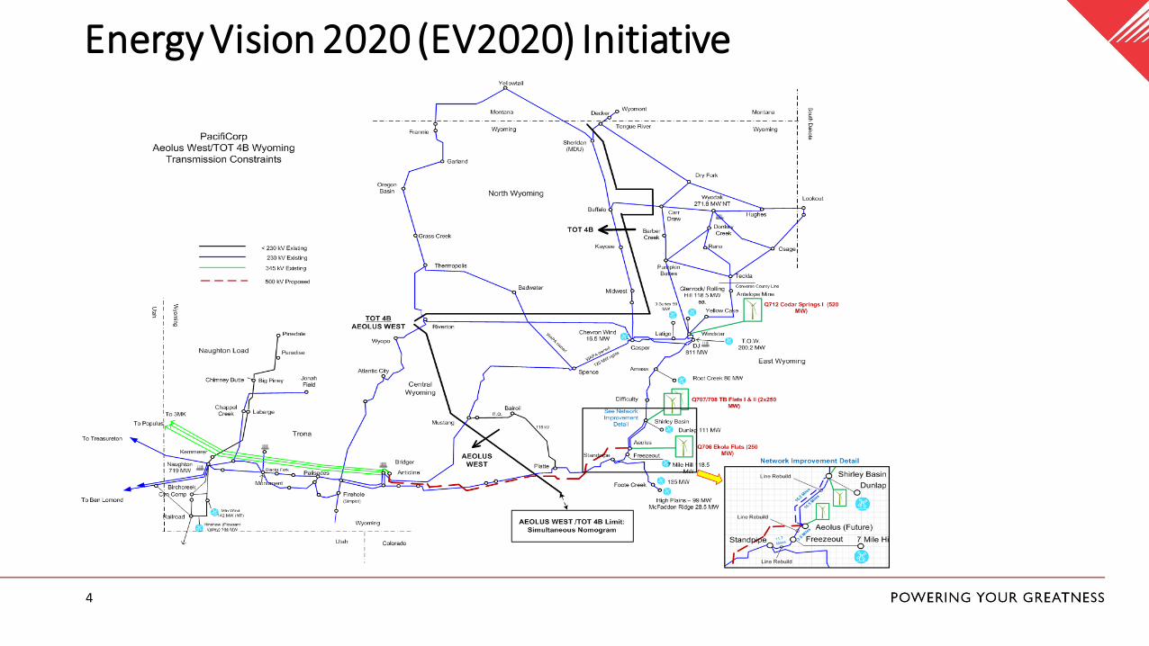
Energy Vision 2020 (EV2020) Initiative
5
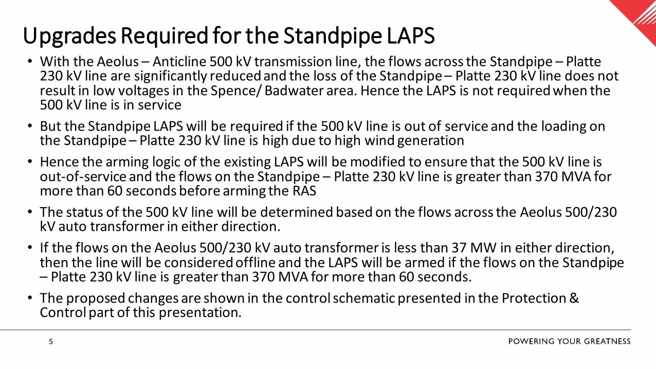
Upgrades Required for the Standpipe LAPS• With the Aeolus – Anticline 500 kV transmission line, the flows across the Standpipe – Platte
230 kV line are significantly reduced and the loss of the Standpipe – Platte 230 kV line does not result in low voltages in the Spence/ Badwater area. Hence the LAPS is not required when the 500 kV line is in service
• But the Standpipe LAPS will be required if the 500 kV line is out of service and the loading on the Standpipe – Platte 230 kV line is high due to high wind generation
• Hence the arming logic of the existing LAPS will be modified to ensure that the 500 kV line is out-of-service and the flows on the Standpipe – Platte 230 kV line is greater than 370 MVA for more than 60 seconds before arming the RAS
• The status of the 500 kV line will be determined based on the flows across the Aeolus 500/230 kV auto transformer in either direction.
• If the flows on the Aeolus 500/230 kV auto transformer is less than 37 MW in either direction, then the line will be considered offline and the LAPS will be armed if the flows on the Standpipe – Platte 230 kV line is greater than 370 MVA for more than 60 seconds.
• The proposed changes are shown in the control schematic presented in the Protection & Control part of this presentation.
Protection & ControlMorteza Rezaee Babak

7
Protection Logic Change
Trip to High Plains(Via mirrored bit)
Loss of Platte line detected at Standpipe
OR
Platte Line Power +
-
60 SEC
60 SEC370 MW
ANDRAS Enabled
Standpipe
SEL-2411
Trip
SEL-2894
2 SEC
10 SEC
Trip to Foote Creek(Via mirrored bit)
TSend loss of path at Platte
(Via mirrored bit)
Platte
SEL-321 (Line Relay)
TLoss of Path received (Via
mirrored bit)
Standpipe
SEL-321 (Line Relay)
37 MW
Aeolus
SEL-2411
XFMR1 |P| +
-
60 SEC
60 SEC
T
TRAS trigger received (Via
mirrored bit)
Standpipe
SEL-2505
8
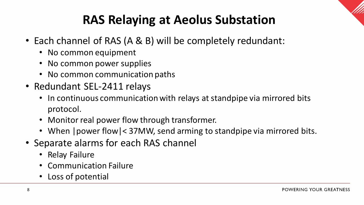
RAS Relaying at Aeolus Substation
• Each channel of RAS (A & B) will be completely redundant:• No common equipment• No common power supplies• No common communication paths
• Redundant SEL-2411 relays• In continuous communication with relays at standpipe via mirrored bits
protocol. • Monitor real power flow through transformer.• When |power flow|< 37MW, send arming to standpipe via mirrored bits.
• Separate alarms for each RAS channel• Relay Failure• Communication Failure• Loss of potential
9
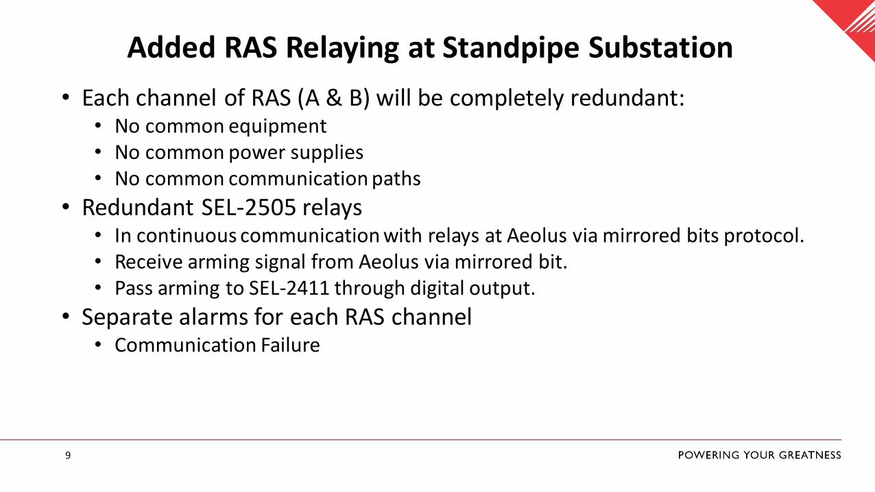
Added RAS Relaying at Standpipe Substation
• Each channel of RAS (A & B) will be completely redundant:• No common equipment• No common power supplies• No common communication paths
• Redundant SEL-2505 relays• In continuous communication with relays at Aeolus via mirrored bits protocol. • Receive arming signal from Aeolus via mirrored bit.• Pass arming to SEL-2411 through digital output.
• Separate alarms for each RAS channel• Communication Failure

CommunicationBrian Nordlund

11
Telecommunications Redundancy
• Power: Dedicated -48VDC telecom battery and charger system at all Comm sites and substations. Dual feeds to rack and dual power supplies on equipment.
• Channel banks, microwave radios and physical media completely redundant and diverse.
• Fiber nodes employ completely redundant hardware; optics, tributary cards, fans, and non-traffic bearing controller cards all redundant in shared chassis.
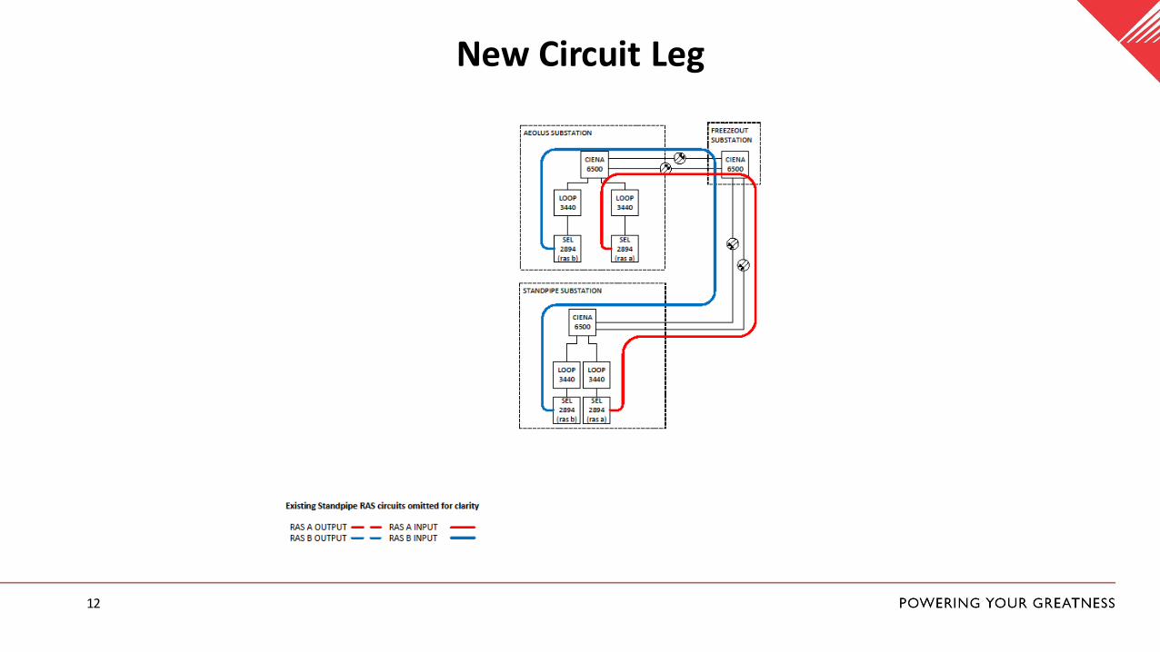
12
New Circuit Leg

13
New Circuit Leg Latency
CIRCUIT
Expected
LATENCY
(ms)
Maximum
Latency (ms)
MEETS LATENCY
REQUIREMENTS
TBD 2.041816 16.0 Yes
TBD 2.041816 16.0 Yes
CIRCUIT DESCRIPTION
Aeolus to Standpipe A
Aeolus to Standpipe B

14
Circuit/System Availability
Availability
99.98723%
99.98723%
99.999998%
CIRCUIT DESCRIPTION
Aeolus to Standpipe A
Aeolus to Standpipe B

Commissioning & Maintenance Plans
Randy Porter
16
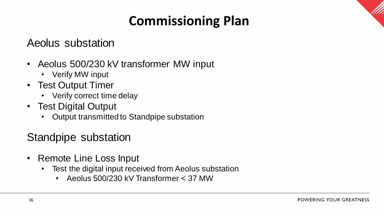
Commissioning Plan
Aeolus substation
• Aeolus 500/230 kV transformer MW input• Verify MW input
• Test Output Timer• Verify correct time delay
• Test Digital Output• Output transmitted to Standpipe substation
Standpipe substation
• Remote Line Loss Input• Test the digital input received from Aeolus substation
• Aeolus 500/230 kV Transformer < 37 MW
17
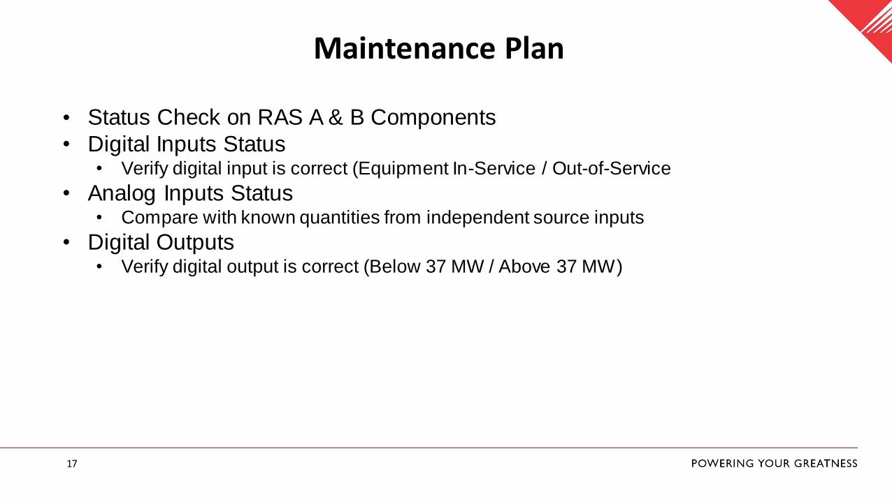
Maintenance Plan
• Status Check on RAS A & B Components
• Digital Inputs Status• Verify digital input is correct (Equipment In-Service / Out-of-Service
• Analog Inputs Status• Compare with known quantities from independent source inputs
• Digital Outputs• Verify digital output is correct (Below 37 MW / Above 37 MW)

Questions


