Page 1
ANTICIPATION & MAINTENANCE – 8 chemin du Jas de Valèze – 13124 PEYPIN
Tél : (33) 04.42.82.80.50 - Fax : (33) 04.42.82.80.86
Web: http://www.mecason.com - Mail: [email protected]
N-CBN30EN-030205
INSTALLATION AND
OPERATING INSTRUCTIONS
FOR THE
SONOR MONITORING UNIT
CBN 30
MECASON ®
This document concern particularly following good:
Customer:
Purchase order N°:
Delivery date:
Electronic box N°:
Page 2
- 2 -
ANTICIPATION & MAINTENANCE – 8 chemin du Jas de Valèze – 13124 PEYPIN
Tél : (33) 04.42.82.80.50 - Fax : (33) 04.42.82.80.86
Web: http://www.mecason.com - Mail: [email protected]
N-CBN30EN-030205
- Preamble -
Thank you for choosing to install a device of surveillance MECASON! If you meet in the installation, or later, any
difficulty, do not hesitate to contact us, your total satisfaction is our first objective.
- Table of Content -
I - SYSTEM FUNCTION________________________________________________________________________ 3
II - TECHNICAL SPECIFICATIONS_____________________________________________________________ 4
III - OPTIONAL CARDS _______________________________________________________________________ 6
III.A - MARD 30______________________________________________________________________________ 6
III.B - MARD 33______________________________________________________________________________ 6
III.C - MARD 31, 32 ET 34 (ANALOG OUTPUT 4-20 MA) ____________________________________________ 6
IV - ELECTROMAGNETIC COMPATIBILITY____________________________________________________ 8
V - MECHANICAL INSTALLATION ____________________________________________________________ 8
V.A - ELECTRONIC UNIT INSTALLATION ______________________________________________________ 8
V.B - SENSORS INSTALLATION _______________________________________________________________ 8
VI - CONNECTION AND ADJUSTEMENTS _____________________________________________________ 10
VI.A - SENSOR CONNECTIONS_______________________________________________________________ 10
VI.B - POWERSUPPLY CONNECTIONS ________________________________________________________ 10
VI.C - UNIT CONFIGURATION _______________________________________________________________ 10
VI.D - SENSOR INPUT REFERENCE LEVEL ADJUSTMENTS ______________________________________ 10
VI.E - ALARM LEVEL SETTINGS _____________________________________________________________ 11
VI.F - ALARM OUTPUTS_____________________________________________________________________ 12
VII - ACQUISITION, DEMULTIPLEXAGE BY A PROGRAMMABLE AUTOMAT OF THE 4-20 MA
MEASUREMENT DELIVREE BY THE MECASONMARD CARDS _________________________________ 14
VII.A - MEASURE ____________________________________________________________________________ 14
VII.B - THE AUTOMAT ________________________________________________________________________ 14
ALARMS ___________________________________________________________________________________ 14
VII.D - HISTORY _____________________________________________________________________________ 15
VIII - PROCEDURE OF TEST/CONTROLE______________________________________________________ 15
IX - INTERPRETATIONS: LEVEL CHANGES AND ALARMS _____________________________________ 16
X - NOTES FOR SPECIFIC INSTALLATIONS ON SKILIFTS IMPLEMENTATION___________________ 18
Page 3
- 3 -
ANTICIPATION & MAINTENANCE – 8 chemin du Jas de Valèze – 13124 PEYPIN
Tél : (33) 04.42.82.80.50 - Fax : (33) 04.42.82.80.86
Web: http://www.mecason.com - Mail: [email protected]
N-CBN30EN-030205
I - SYSTEM FUNCTION
Each sensor input is activated and read individually
and sequentially for 4 to 12 seconds by the sensor input
scanning electronics.
Only the changes in the measurement levels are
monitored.
The alarm limits are not expressed in terms of
physical units, thus avoiding an important source of
monitoring error. With MECASON, the reference
level established by the initial sensor input adjustment
forms the base for the alarm levels. The alarm levels,
in turn, represent then factors of increase over the
individual reference level and allow a closer
monitoring of each measurement point.
MECASON can not, therefore, be used to establish
the mechanical condition of the machine upon
installation. Only the developments in the measured
levels, or lack thereof, over time can be considered a
reliable source of information. The rate of change in
measurement levels being the most useful indicator in
judging the condition of the mechanical component in
question.
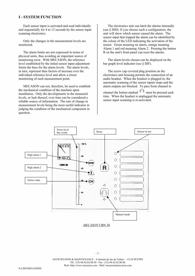
The electronics unit can latch the alarms internally
(see § IIID). If you choose such a configuration, the
unit will show which sensor caused the alarm. The
sensor input that tripped the alarm can be identified by
the colour of the LED indicating the activation of the
sensor. Green meaning no alarm, orange meaning
Alarm 1 and red meaning Alarm 2. Pressing the button
R on the unit's front panel can reset the alarms.
The alarm levels chosen can be displayed on the
bar graph level indicator (see § IIIF).
The screw cap covered plug position on the
electronics unit housing permits the connection of an
audio headset. When the headset is plugged in, the
automatic scanning of the sensor inputs stops and the
alarm outputs are blocked. To pass from channel to
channel the button marked must be pressed each
time. When the headset is unplugged the automatic
sensor input scanning is re-activated.
MECASON CBN 30
Noise level
Bar graph.
High alarm 1
Reset
Manuel mode
Sensor state
High alarm 2
Sensor in use
Page 4
- 4 -
ANTICIPATION & MAINTENANCE – 8 chemin du Jas de Valèze – 13124 PEYPIN
Tél : (33) 04.42.82.80.50 - Fax : (33) 04.42.82.80.86
Web: http://www.mecason.com - Mail: [email protected]
N-CBN30EN-030205
II - TECHNICAL SPECIFICATIONS
ELECTRONICS UNIT
- Number of available inputs 8
- Sampling time of each selected Input during the scanning cycle 6 to 14 s
- Number of inputs scanned, selectable via jumper 1 to 8 inputs
- Frequency band monitored 100Hz to 12kHz
- Two independently adjustable alarm limits
- Internal latching of alarms yes/no, (selectable via jumper)
- Alarm outputs in positive and negative security
- delays 3 approx.
- maximum voltage limit 230 volts
- maximum current limit 5 A
- maximum power limit 250 VA for AC, 50 to 150 for DC
(please consult us)
- Analogue outputs
- front panel indicator length 0 to 100%, 125mm
- standard analog output (card MARD 31, 32 or 34) 4 - 20 mA
- Terminal connection wire cross-section 1,5 mm2
- Power supply 220 V, 50 Hz
- Power consumption less than 10 VA
- Electrical protection fuse 5 x 20 slow burn plus GMOVE
- Operating temperature limits 0 to 50 °C
- Polycarbonate housing rating IP 65
- Housing dimensions 160 x 240 x 90 mm
(excluding cable passages)
- Weight approx. 1.5 kg
SENSORS
- Operating temperature limits -20 °C to +60°C
- Rating IP 65
(upon demand, submersible 5 bars)
- Installation hardware floating washer and screws
CHC Ø 5
- Weight excluding cable approx. 50 g
- Sensor cable flexible, shielded 0,22 mm2, PVC
- Sensor body stainless steel 316 L
Page 5
- 5 -
ANTIC
IPATIO
N &
MAIN
TENANCE – 8 ch
emin du Jas d
e Valèze –
13124 PEYPIN
Tél : (3
3) 0
4.42.82.80.50 - F
ax : (3
3) 0
4.42.82.80.86
Web: h
ttp://w
ww.m
ecason.co
m - M
ail: mecaso
n@mecaso
n.co
m
N-C
BN30EN-030205
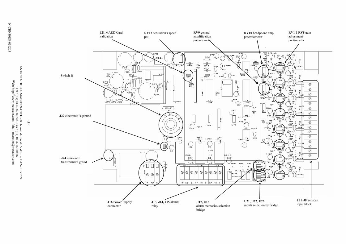
J16 Power Supply
connector
J13, J14, J15 alamrs
relay
U17, U18
alarm memories selection
bridge
U21, U22, U23
inputs selection by bridge
J1 à J8 Sensors
input block
J24 armoured
transformer's groud
J22 electronic 's ground
Switch I1
J21 MARD Card
validation RV12 scrutation's speed
pot.
RV9 general
amplification
potentiometer
RV10 headphone amp
potentiometer
RV1 à RV8 gain
adjustment
poetiometer
Page 6
- 6 -
ANTICIPATION & MAINTENANCE – 8 chemin du Jas de Valèze – 13124 PEYPIN
Tél : (33) 04.42.82.80.50 - Fax : (33) 04.42.82.80.86
Web: http://www.mecason.com - Mail: [email protected]
N-CBN30EN-030205
III - OPTIONAL CARDS
The MARD card offers diverse functions according to the version ordered.
MARD 30 Permits up to 4 separate Alarm 2 outputs for monitoring several machines with the same unit.
To disarm the alarms in the case of machine shut down, 4 optocoupler inputs are provided to activate
the monitoring only with the presence of a pre-defined voltage at the input.
MARD 31 Same as MARD 30 + multi-plexed analog output 4-20 mA with integrated identification of input 1.
MARD 32 Multi-plexed analog output 4-20 mA with integrated identification of input 1 only.
MARD 33 Optocoupler inputs only, to restrict monitoring to predefined conditions ( eg. hydro electric turbines;
monitoring only during production of electricity, screw type compressors; monitoring only under
load, ski-lift station gear boxes; monitoring only more than 20 secs after system start, etc.)
MARD 34 Function MARD 32 + Function MARD 33
III.A - MARD 30 Provides up to 4 separate Alarm 2 outputs.
Necessary when several machines (up to 4) are to
be monitored with the same electronics unit and
MECASON must shut down the machines individually
upon reaching the alarm level 2.
To prevent a false "defective sensor" alarm when a
single machine is shut down, the optocoupler inputs
can be used to validate the alarm conditions only when
the machine is in operation.
With this card, the alarm N°1 and the "defective
sensor" alarm are generated by the motherboard ( a
single output per electronics unit).
To validate the alarm outputs, a pre-defined voltage
must be present at the optocoupler input. The absence
of the input voltage blocks all alarm outputs for the
corresponding machine and can be used to avoid false
alarms during machine power-up or when the machine
is operating in abnormal modes. For example; power-
up of a ski lift station (no monitoring until a stable
speed has been attained), the operation of a
hydroelectric turbine (no monitoring until the generator
has been connected to the distribution network), or
operation of a screw type compressor (no monitoring
while the screws are not delivering compressed air). In
all cases, the system controlling the machine must
generate the alarm validation voltage to activate
monitoring (24, or 48 volts, DC or AC). The above
mentioned control voltage level and the grouping of
the alarm outputs for the machines to be monitored
must be defined when ordering the card
III.B - MARD 33 This option features the optocoupler input function
only and is used to block the standard alarm outputs
("defective sensor", Alarm 1 and Alarm 2) available on
the electronics unit motherboard.
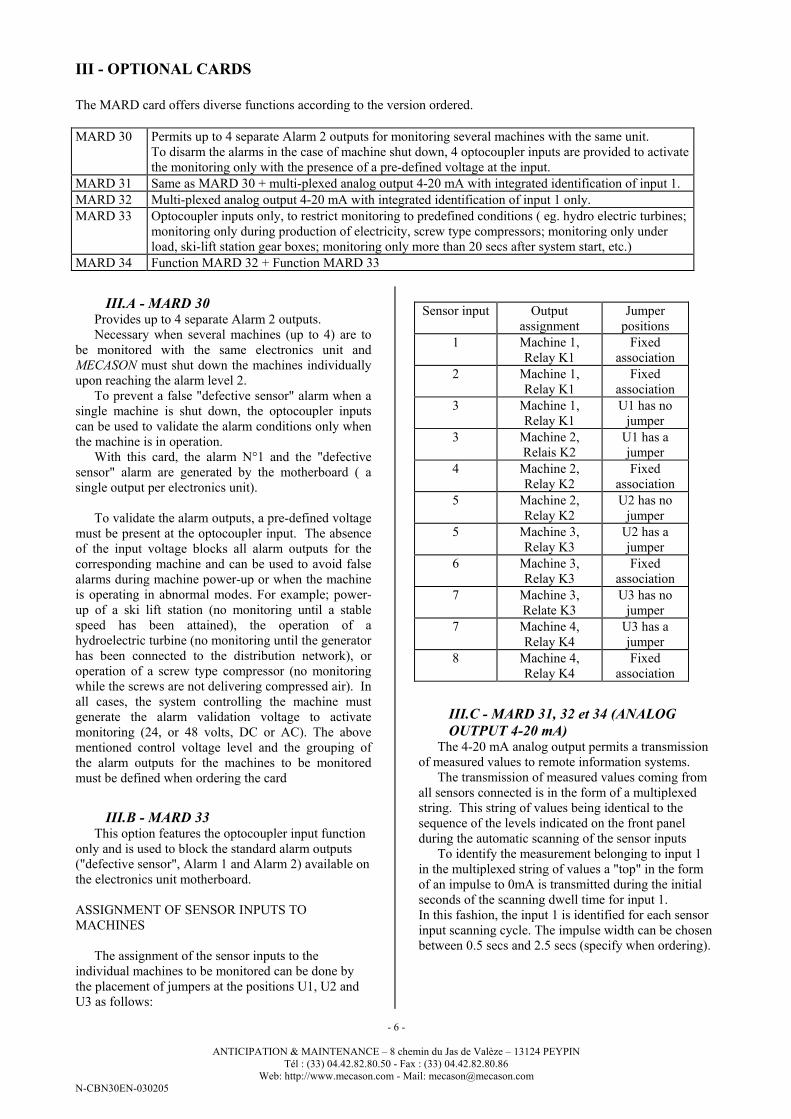
ASSIGNMENT OF SENSOR INPUTS TO
MACHINES
The assignment of the sensor inputs to the
individual machines to be monitored can be done by
the placement of jumpers at the positions U1, U2 and
U3 as follows:
Sensor input Output
assignment
Jumper
positions
1 Machine 1,
Relay K1
Fixed
association
2 Machine 1,
Relay K1
Fixed
association
3 Machine 1,
Relay K1
U1 has no
jumper
3 Machine 2,
Relais K2
U1 has a
jumper
4 Machine 2,
Relay K2
Fixed
association
5 Machine 2,
Relay K2
U2 has no
jumper
5 Machine 3,
Relay K3
U2 has a
jumper
6 Machine 3,
Relay K3
Fixed
association
7 Machine 3,
Relate K3
U3 has no
jumper
7 Machine 4,
Relay K4
U3 has a
jumper
8 Machine 4,
Relay K4
Fixed
association
III.C - MARD 31, 32 et 34 (ANALOG
OUTPUT 4-20 mA) The 4-20 mA analog output permits a transmission
of measured values to remote information systems.
The transmission of measured values coming from
all sensors connected is in the form of a multiplexed
string. This string of values being identical to the
sequence of the levels indicated on the front panel
during the automatic scanning of the sensor inputs
To identify the measurement belonging to input 1
in the multiplexed string of values a "top" in the form
of an impulse to 0mA is transmitted during the initial
seconds of the scanning dwell time for input 1.
In this fashion, the input 1 is identified for each sensor
input scanning cycle. The impulse width can be chosen
between 0.5 secs and 2.5 secs (specify when ordering).
Page 7
- 7 -
ANTICIPATION & MAINTENANCE – 8 chemin du Jas de Valèze – 13124 PEYPIN
Tél : (33) 04.42.82.80.50 - Fax : (33) 04.42.82.80.86
Web: http://www.mecason.com - Mail: [email protected]
N-CBN30EN-030205
TECHNICAL CARACTERISTICS
- Installation on the electronics unit motherboard plug-in
- Maximum allowable transmission path resistance 400 Ohms,
(500 on demand)
- Relays outputs (positive and negative security)
- Maximum switching voltage 125 volts
- Maximum switching current 1 amp
- Maximum switching power 60 VA (AC.), 50 W (DC.)
- Optocoupler input voltage specify upon ordering
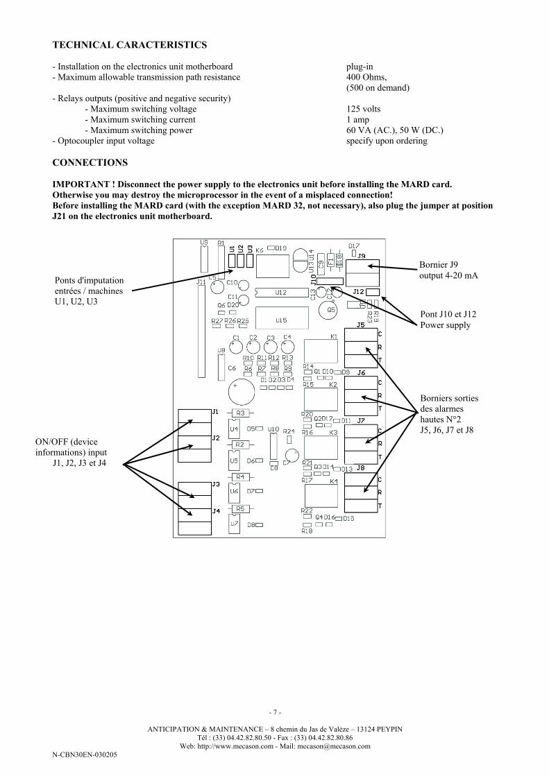
CONNECTIONS
IMPORTANT ! Disconnect the power supply to the electronics unit before installing the MARD card.
Otherwise you may destroy the microprocessor in the event of a misplaced connection!
Before installing the MARD card (with the exception MARD 32, not necessary), also plug the jumper at position
J21 on the electronics unit motherboard.
Ponts d'imputation
entrées / machines
U1, U2, U3
Bornier J9
output 4-20 mA
ON/OFF (device
informations) input
J1, J2, J3 et J4
Borniers sorties
des alarmes
hautes N°2
J5, J6, J7 et J8
Pont J10 et J12
Power supply
Page 8
- 8 -
ANTICIPATION & MAINTENANCE – 8 chemin du Jas de Valèze – 13124 PEYPIN
Tél : (33) 04.42.82.80.50 - Fax : (33) 04.42.82.80.86
Web: http://www.mecason.com - Mail: [email protected]
N-CBN30EN-030205
IV - ELECTROMAGNETIC COMPATIBILITY
The system working with weak currents, the risks
of electromagnetic disturbances are important. It is thus
particularly important to verify well the quality of the
signals by listening in the helmet to all the ways, but
before, we invite you to respect well some elementary
precautions during the installation, namely: - to
install(settle) the case far from the sources of
disturbances (contacteurs, cable of powers
crossed(gone through) by common(current) "minced
meats")
On engines, avoid implanting the sensors
towards(as for) the box with borders (especially on
machines with variable speed) - avoid absolutely
making walk the cables of the sensors on the same
cable tray as the drivers of power, especially for
machines with variable speed (in case of obligation,
protect them by a métalloplastique girdle (kind(genre)
CAPRIPLAST) earthed by its two extremities).
In case of doubt, please, do not hesitate to consult
us!
V - MECHANICAL INSTALLATION
V.A - ELECTRONIC UNIT
INSTALLATION
Thanks to the IP 65 rated housing, the electronics
unit can either be placed outdoors close to the machines
or in a rack. By placing the unit close to the machines,
the measured levels can be directly observed on the
front panel during grease applications and thus provide
a direct confirmation that the grease has actually
reached the bearing.
The distance between the sensors and the electronics
unit can easily exceed 100m (case encountered where
the machines are in an intrinsic protection zone) and
allows a problem free placement of the housing.
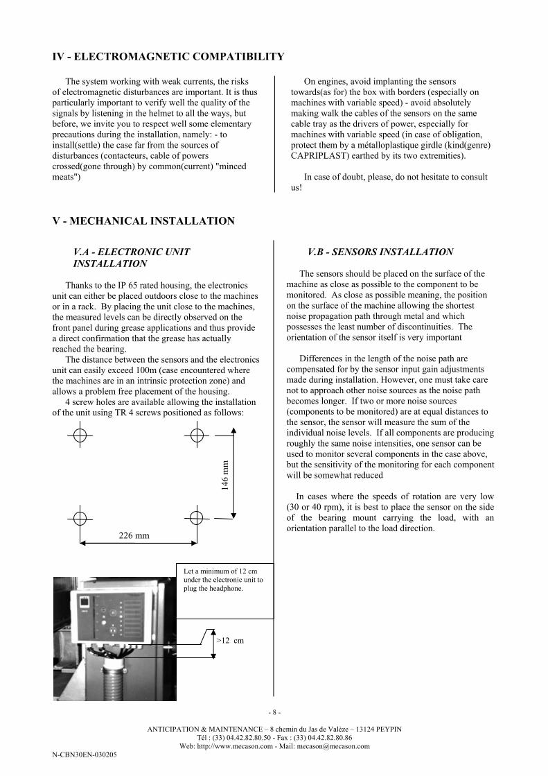
4 screw holes are available allowing the installation
of the unit using TR 4 screws positioned as follows:
V.B - SENSORS INSTALLATION
The sensors should be placed on the surface of the
machine as close as possible to the component to be
monitored. As close as possible meaning, the position
on the surface of the machine allowing the shortest
noise propagation path through metal and which
possesses the least number of discontinuities. The
orientation of the sensor itself is very important
Differences in the length of the noise path are
compensated for by the sensor input gain adjustments
made during installation. However, one must take care
not to approach other noise sources as the noise path
becomes longer. If two or more noise sources
(components to be monitored) are at equal distances to
the sensor, the sensor will measure the sum of the
individual noise levels. If all components are producing
roughly the same noise intensities, one sensor can be
used to monitor several components in the case above,
but the sensitivity of the monitoring for each component
will be somewhat reduced
In cases where the speeds of rotation are very low
(30 or 40 rpm), it is best to place the sensor on the side
of the bearing mount carrying the load, with an
orientation parallel to the load direction. 226 mm
146 m
m
Let a minimum of 12 cm
under the electronic unit to
plug the headphone.
>12 cm
Page 9
- 9 -
ANTICIPATION & MAINTENANCE – 8 chemin du Jas de Valèze – 13124 PEYPIN
Tél : (33) 04.42.82.80.50 - Fax : (33) 04.42.82.80.86
Web: http://www.mecason.com - Mail: [email protected]
N-CBN30EN-030205
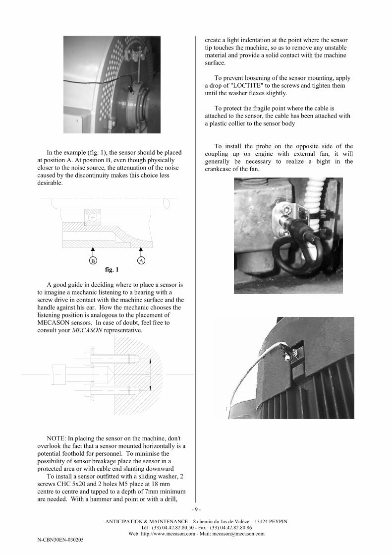
In the example (fig. 1), the sensor should be placed
at position A. At position B, even though physically
closer to the noise source, the attenuation of the noise
caused by the discontinuity makes this choice less
desirable.
fig. 1
A good guide in deciding where to place a sensor is
to imagine a mechanic listening to a bearing with a
screw drive in contact with the machine surface and the
handle against his ear. How the mechanic chooses the
listening position is analogous to the placement of
MECASON sensors. In case of doubt, feel free to
consult your MECASON representative.
NOTE: In placing the sensor on the machine, don't
overlook the fact that a sensor mounted horizontally is a
potential foothold for personnel. To minimise the
possibility of sensor breakage place the sensor in a
protected area or with cable end slanting downward
To install a sensor outfitted with a sliding washer, 2
screws CHC 5x20 and 2 holes M5 place at 18 mm
centre to centre and tapped to a depth of 7mm minimum
are needed. With a hammer and point or with a drill,
create a light indentation at the point where the sensor
tip touches the machine, so as to remove any unstable
material and provide a solid contact with the machine
surface.
To prevent loosening of the sensor mounting, apply
a drop of "LOCTITE" to the screws and tighten them
until the washer flexes slightly.
To protect the fragile point where the cable is
attached to the sensor, the cable has been attached with
a plastic collier to the sensor body
To install the probe on the opposite side of the
coupling up on engine with external fan, it will
generally be necessary to realize a bight in the
crankcase of the fan.
A B
Page 10
- 10 -
ANTICIPATION & MAINTENANCE – 8 chemin du Jas de Valèze – 13124 PEYPIN
Tél : (33) 04.42.82.80.50 - Fax : (33) 04.42.82.80.86
Web: http://www.mecason.com - Mail: [email protected]
N-CBN30EN-030205
VI - CONNECTION AND ADJUSTEMENTS
VI.A - SENSOR CONNECTIONS
The centre conductor for each sensor must be
connected to the upper terminal of each input terminal
pair. The cable shield in turn is to be connected to
ground (lower terminal).
Note: To ensure an easy orientation in the case of
MECASON alarms, choose a logical sequence for the
sensors connected. For example, first the sensors of
the motor followed by the sensors of the pump in the
order that they are found on the machines along the
axis of rotation.
VI.B - POWERSUPPLY CONNECTIONS
The circuit is outfitted with a triple terminal. (See point
B)
The ground wire must be connected. If not, the
electronics unit's shielding against induced noise will
not function.
A 160mA slow burn fuse is used to protect the circuits
powered by 230VAC.
A GMOVE V250L20 is used to protect against voltage
peaks.
VI.C - UNIT CONFIGURATION
VI.C.1 - CHOOSING THE NUMBER OF
ACTIVE SENSOR INPUTS.
The MECASON Electronics unit is designed to
accommodate from 1 to 8 sensors. To restrict the
automatic scanning of the sensor inputs to only those
inputs outfitted with sensors (active inputs), 3 jumper
positions are available (points U21, U22, et U23) on
the circuit board. The last input scanned is determined
as follows:
N° of input 1 2 3 4 5 6 7 8
U21 - J - J - J - J
U22 - - J J - - J J
U23 - - - - J J J J
J=jumper
VI.C.2 - INTERNAL LATCHING OF
ALARMS
The jumpers U17 and U18 allow you to latch
internally the alarm conditions for Alarm 2 and Alarm
1 respectively with the jumper in position the alarms
are latched and with the jumper out of place the alarms
are not latched. The alarm "defective sensor" cannot be
latched.
If you wish to latch the alarms only under certain
conditions (for example machine operating or machine
under load), you have two possibilities:
- Latch the alarms with exterior relays only
- Install the optional circuit MARD 33 which
provides a signal input for validation of the alarms
under pre-defined conditions.
VI.C.3 - ADJUSTEMENT OF THE
SENSOR INPUT SCANNING RATES
Using the potentiometer RV 12 (position K) the
dwell time for each sensor input during scanning can
be adjusted between 6 and 14 seconds.
For most applications a dwell time of about 10
seconds gives satisfactory results.
VI.C.4 - GROUNDING OF THE
ELECTRONICS UNIT'S EARTH TRACES
The earth for the electronics unit can be connected
to ground via the jumper J22 (just below the rotating
switch I1). Depending on the quality of the earth at the
installation site, it may or may not be best to connect
the earth and electronics 0V traces to the ground line.
In listening to the sensor signal via headset, you can
determine whether or not you should connect to
ground.
VI.D - SENSOR INPUT REFERENCE
LEVEL ADJUSTMENTS
MECASON uses a purely relative measurement in
its monitoring. The base of the measurement used for
monitoring is a reference level established by the
person installing the unit and considered to reflect the
normal operating condition of the machine.
Note: Before making the reference level
adjustment, assure that the lubrication of the part to be
surveyed is optimised.
We suggest using the level 20% on the front panel
as the reference level. This level is high enough to
detect a defective sensor with a minimum level limit
and low enough to allow an effective indication of an
insufficient lubrication and/or a possible mechanical
degradation with alarm levels 1 and 2 placed between
20% and 90%.
Page 11
- 11 -
ANTICIPATION & MAINTENANCE – 8 chemin du Jas de Valèze – 13124 PEYPIN
Tél : (33) 04.42.82.80.50 - Fax : (33) 04.42.82.80.86
Web: http://www.mecason.com - Mail: [email protected]
N-CBN30EN-030205
The reference level adjustment is made with two
successive levels of amplification. First, for each
sensor input individually with the potentiometers RV1
to RV8. And second, a general amplification
adjustment for all inputs at once uses the potentiometer
RV9. To assure the passage of healthy sensor signal to
the second level of amplification, the adjustment of the
individual input gain should be made so as to maintain
the highest gain possible.
To adjust each sensor input proceed as follows:
BEFORE ADJUSTING THE INPUTS
- Check that the rotating switch I1 is set at position
"M" (Measure),
- Power-up the machine(s) monitored by the
MECASON unit to be adjusted.
- Before plugging in the headset, which would stop
the sensor scanning, confirm that the scanning
covers all sensor inputs with sensors connected and
only those with sensors. Should this not be the
case, regroup the sensor connections so as to leave
no gaps from the first to the last input used and/or
reposition the jumpers (U21,22,23) as described in
paragraph C1.
- Pull lightly on each sensor cable so as to confirm
that the wires a firmly held in the terminal blocks.
Check at the same time that the polarity of the
sensor wires is correct (signal above, ground below
for each pair). An inverted polarity can damage
the circuit !!
YOU ARE NOW READY TO ADJUST THE
REFERENCE LEVELS !
INPUT REFERENCE LEVEL ADJUSTMENT
NOTE: All potentiometers used are type 22 turns and
logarithmic.
- Plug in the headset to block the automatic input
scanning and using the input active LEDs for
orientation, step manually with the button marked
until input 1.is activated.
-Starting from input 1, listen to each of the inputs
briefly to assure that the noise heard is of
mechanical origin (if the volume at the headset is
too high or low adjust the volume with the
potentiometer RV10 position G). If you are not
sure of the noise's origin, shut down the machine
and listen as the machine slows so as to confirm the
sources of the noises heard. Check the sensor
connection or installation on the machine if you are
still in doubt. Once convinced that all noises heard
are predominantly mechanical, select again input 1.
-NOTE: During final factory inspection the
potentiometers RV1 to RV8 are adjusted to 18 turns
- Using the potentiometer RV9 (amplification
general, position E) adjust the level for input 1 to
about 50%.
Step manually with the button marked to
determine which input has the lowest reading.
- Choose the input with the lowest reading and adjust
the level to 20 % using RV9 only.
- Activating manually each of the remaining sensor
inputs, adjust each to 20% using only the
corresponding individual gain potentiometer RV1
to RV8.
YOUR MECASON IS NOW READY TO MONITOR!
Unplug the headset and check one last time with
the automatic scanning that all levels show 20%.
Using the potentiometers RV1 to RV8 only retouch the
inputs showing slight deviations.
Attention: If you are forced to change the
adjustment of the potentiometer RV9 to have 20% for
any input, you must re-adjust all remaining inputs with
RV1 to RV8 !
Never forget to unplug the headphone !! If the
headphone is plugged, alarms are quiet!
VI.E - ALARM LEVEL SETTINGS
The alarm levels can be shown on the front panel
indicator. Simply select the desired alarm with the
rotating switch I1 (position H)
The switch positions are as follows:
Function Switch
position
Correspondin
g
potentiometer
Measure M -
Defective sensor 1 RV14
Alarm N°1 2 RV15
Alarm N°2 3 RV13
For a reference level of 20%, we suggest the following
alarm settings (ball bearing monitoring):
Defective sensor 10%,
Alarm N°1 50%, increase factor 2,5
(50/20)
Alarm N°2 80%, increase factor 4,0
(80/20)
At the factory final inspection the above mentioned
levels are pre-set. To set other levels proceed as
follows:
- Select the alarm level to be set with the switch I1
- Adjust the desired level with the corresponding
potentiometer (see table above)
Page 12
- 12 -
ANTICIPATION & MAINTENANCE – 8 chemin du Jas de Valèze – 13124 PEYPIN
Tél : (33) 04.42.82.80.50 - Fax : (33) 04.42.82.80.86
Web: http://www.mecason.com - Mail: [email protected]
N-CBN30EN-030205
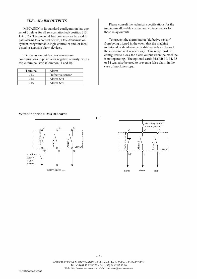
VI.F - ALARM OUTPUTS
MECASON in its standard configuration has one
set of 3 relays for all sensors attached (position J13,
J14, J15). The potential free contacts can be used to
pass alarms to a control centre, a tele-transmission
system, programmable logic controller and /or local
visual or acoustic alarm devices.
Each relay output features connection
configurations in positive or negative security, with a
triple terminal strip (Common, T and R).
Terminal Alarm
J13 Defective sensor
J14 Alarm N°1
J15 Alarm N°2
Please consult the technical specifications for the
maximum allowable current and voltage values for
these relay outputs.
To prevent the alarm output "defective sensor"
from being tripped in the event that the machine
monitored is shutdown, an additional relay exterior to
the electronic unit is necessary. This relay must be
configured to block the alarm output when the machine
is not operating. The optional cards MARD 30, 31, 33
or 34 .can also be used to prevent a false alarm in the
case of machine stops.
Without optional MARD card: OR
Auxiliary contact
« on » system
alarm alarm stop
Defective sensor
Alarm
2
Alarm
1
C C C
NNF N
CBN 30
Relay, infos …
Auxiliary
contact
« on »
system
Defective sensor
Alarm
2
Alarm
1
C C C
NNF N
CBN 30
Page 13
- 13 -
ANTICIPATION & MAINTENANCE – 8 chemin du Jas de Valèze – 13124 PEYPIN
Tél : (33) 04.42.82.80.50 - Fax : (33) 04.42.82.80.86
Web: http://www.mecason.com - Mail: [email protected]
N-CBN30EN-030205
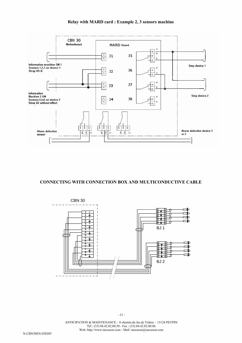
Relay with MARD card : Example 2, 3 sensors machine
CONNECTING WITH CONNECTION BOX AND MULTICONDUCTIVE CABLE
1 + 1 2 + 2 3 + 3 4 + 4 5 + 5 6 + 6 7 + 7 8 + 8
CBN 30
BJ 1
BJ 2
Page 14
- 14 -
ANTICIPATION & MAINTENANCE – 8 chemin du Jas de Valèze – 13124 PEYPIN
Tél : (33) 04.42.82.80.50 - Fax : (33) 04.42.82.80.86
Web: http://www.mecason.com - Mail: [email protected]
N-CBN30EN-030205
VII - ACQUISITION, DEMULTIPLEXAGE BY a PROGRAMMABLE AUTOMAT OF
THE 4-20 mA MEASUREMENT DELIVREE BY the MECASONMARD CARDS
Objective:
The follow-up of the sensors connected to the
MECASON is done by cyclic examination. A 4-20 mA
Signal is delivered by MARD card, it is proportional to
the bar graph display, discontinuous and stopped
according to the rate/rhythm of examination. To allow
the automat to exploit the measurement signal, it must
be programmed. The programming principles are
presented in the following lines.
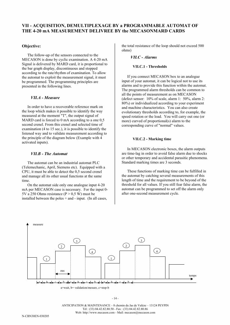
VII.A - Measure
In order to have a recoverable reference mark on
the loop which makes it possible to identify the way
measured at the moment "T", the output signal of
MARD card is forced to 0 mA according to a one 0,5
second crenel. From this crenel and selected time of
examination (4 to 15 sec.), it is possible to identify the
listened way and to validate measurement according to
the principle of the diagram below (Example with 4
activated inputs).
VII.B - The Automat
The automat can be an industrial automat PLC
(Telemechanic, April, Siemens etc). Equipped with a
CPU, it must be able to detect the 0,5 second crenel
and manage all its other usual functions at the same
time.
On the automat side only one analogue input 4-20
mA per MECASON case is necessary. For the input 0-
5V a 250 Ohms resistance (P > 0,5 W) must be
installed between the poles + and - input. (In all cases,
the total resistance of the loop should not exceed 500
ohms)
VII.C - Alarms
VII.C.1 - Thresholds
If you connect MECASON box to an analogue
input of your automat, it can be logical not to use its
alarms and to provide this function within the automat.
The programmed alarm thresholds can be common to
all the points of measurement as on MECASON
(defect sensor: 10% of scale, alarm 1: 50%, alarm 2:
80%) or individualized according to your experiment
and machine characteristics. You can also create
evolutionary thresholds according to, for example, the
speed rotation or the load. You will carry out one (or
more) curved of proportional(s) alarm to the
corresponding curve of "normal" values.
VII.C.2 - Marking time
In MECASON electronic boxes, the alarm outputs
are time-lag in order to avoid false alarm due to shocks
or other temporary and accidental parasitic phenomena.
Standard marking times are 3 seconds.
These functions of marking time can be fulfilled in
the automat by catching several measurements of this
length of time and the requirement to be beyond of the
threshold for all values. If you still fear false alarm, the
automat can be programmed to set off the alarm only
after one-second measurement cycle.
temps
measure
pas
1
2
3
4
1
2
3
4
a b c b c b c b a b c b
a=wait, b= validation/mesure, c=step-b
Page 15
- 15 -
ANTICIPATION & MAINTENANCE – 8 chemin du Jas de Valèze – 13124 PEYPIN
Tél : (33) 04.42.82.80.50 - Fax : (33) 04.42.82.80.86
Web: http://www.mecason.com - Mail: [email protected]
N-CBN30EN-030205
.
VII.D - History
It is often interesting to know how the signal
evolved/moved before release an alarm. With a history
(recording of the values of measurement) it is possible
to know if the alarm threshold were crossed brutally
(case of a breakage) or gradually (rather a degradation
of lubrication or mechanics). It can be also interesting
to compare the evolutions of the various sensors of the
same machine.
VIII - PROCEDURE OF TEST/CONTROLE
Like any device providing a function of security, it
is desirable to control periodically the correct operation
of chain MECASON. The operation must be carried
out machine in service.
- General operation: The system is self-monitored by
the relay "defect sensor". To check that while
disconnecting a sensor, or while stopping the
machine, the relay returns at rest.
- Quality of the signal: Listen to the quality of the
signal with the headphonet; to check if you
recognize the noise of the machine clearly. In case
of doubt, you can strike the metal part of the body
of the sensor with a screwdriver or any other metal
tool. You must perceive a Net noise. The bar-graph
must react.
- Operation of relays on high thresholds: The
Simplest is to cause the swing of the relays by
lowering the threshold values. The headphone
must be disconnected.
+ turn the I1 switch on the S2 position
+ check first of all if the adjustment of the threshold
+ put the threshold lower to 10%
+ High alarm n° 1 must start
+ turn the I1 switch on the S3 position
+ check first of all if the adjustment of threshold were
with the good value
+ lower the threshold to 14 or 16%
+ High alarm n°2 must start
+ restore the threshold values S2 and S3
+ replace I1 in position M
+ Reset alarms (button R). The check operation is
finished
Page 16
- 16 -
ANTICIPATION & MAINTENANCE – 8 chemin du Jas de Valèze – 13124 PEYPIN
Tél : (33) 04.42.82.80.50 - Fax : (33) 04.42.82.80.86
Web: http://www.mecason.com - Mail: [email protected]
N-CBN30EN-030205
IX - INTERPRETATIONS: LEVEL CHANGES AND ALARMS
Symptoms Analysis When,... action
1 level dropping Most probably a result of
machine run-in.
Listen to sensor signal with headset.
Re-adjust the individual reference level so
as to allow a common alarm level limit
2 Level risen slightly
(+ 30 to + 50%).
Change in machines
operating condition or
possible approaching
insufficient lubrication.
Keep in mind that a worn
ball bearing can produce
levels15 to 40 times higher
than the same well greased
ball bearing in good
condition
Apply grease to bearing
Wait for any further level increase.
3 Level continues to rise and
the Alarm 1 has been
tripped
Most probably an
insufficient lubrication.
- Apply grease, top off oil level
- Check for contaminants in the bearing
housing,
- Inspect the machine for other obvious
external problem sources in the machines
direct vicinity.
4 In spite of application of
lubricants, the alarm level
rests constant
See § 6 and 6b below.
The lubrication was not the
cause of the alarm.
The ball bearing is most
likely showing signs of
wear.
If the machinery is complex vibrations
measurement may be justified.
If the machine is simple, divide the level by
2 using the corresponding individual input
gain adjustment potentiometers RV1 to
RV8. Do not forget to note this
adjustment!
With wear, a ball bearing tends to need
more and more frequent grease applications
5 After grease application the
alarm 1 is tripped again in
the following weeks.
Possible grease destruction
or loss due to temperature
peaks
Apply grease again
6 After grease application the
alarm 1 is tripped before
the standard greasing
interval has completely
lapsed.
The ball bearing is slightly
worn and now has a shorter
greasing interval.
Apply grease with the alarm 1 condition.
The greasing interval will continue to
shorten with the passage of time until an
application of grease no longer can prevent
an increase in the noise level
6 b After an application of
grease the level drops then
regains its previous level in
the following hour
The ball bearing is most
likely in poor mechanical
condition
assuming that the bearing
does not have too much
play (see §9 below).
Follow and further level developments
7 In spite of assuring proper
lubrication and having
verified the non-existence
of external causes
(fixation, other
machines,...) the measured
level continues to rise
progressively.
You are witnessing the
slow deterioration in the
bearings mechanical
condition.
Level factor 3 over new is not alarming but
certainly serious. We suggest re-adjusting
the gain of the input (as in §4) to halve the
level. Note the date of the adjustment. If
the time between double-increases shortens
consistently, change the bearing or at least
take a diagnostic vibrations measurement to
establish the bearing's condition.
8 Alarm level 2 is tripped
before being able to react
to alarm level 1
Sign of mechanical
breakage ( ruptured cage
etc.) or radical changes in
the lubrication of the
bearing ( grease
destruction, absence of oil,
contamination etc°.
Listen to the sensor signal with the headset
to have an idea of the type of problem.
Where source is not obvious after having
assured proper lubrication, arrange a
vibrations measurement immediately or
shut down the machine and open the
bearing housing
Page 17
- 17 -
ANTICIPATION & MAINTENANCE – 8 chemin du Jas de Valèze – 13124 PEYPIN
Tél : (33) 04.42.82.80.50 - Fax : (33) 04.42.82.80.86
Web: http://www.mecason.com - Mail: [email protected]
N-CBN30EN-030205
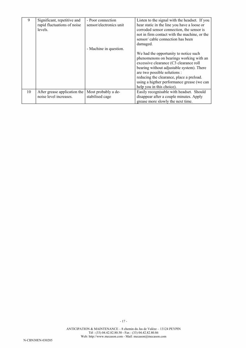
9 Significant, repetitive and
rapid fluctuations of noise
levels.
- Poor connection
sensor/electronics unit
- Machine in question.
Listen to the signal with the headset. If you
hear static in the line you have a loose or
corroded sensor connection, the sensor is
not in firm contact with the machine, or the
sensor/ cable connection has been
damaged.
We had the opportunity to notice such
phenomenons on bearings working with an
excessive clearance (C3 clearance roll
bearing without adjustable system). There
are two possible solutions :
reducing the clearance, place a preload.
using a higther performance grease (we can
help you in this choice).
10 After grease application the
noise level increases.
Most probably a de-
stabilised cage
Easily recognisable with headset. Should
disappear after a couple minutes. Apply
grease more slowly the next time.
Page 18
- 18 -
ANTICIPATION & MAINTENANCE – 8 chemin du Jas de Valèze – 13124 PEYPIN
Tél : (33) 04.42.82.80.50 - Fax : (33) 04.42.82.80.86
Web: http://www.mecason.com - Mail: [email protected]
N-CBN30EN-030205
X - NOTES FOR SPECIFIC INSTALLATIONS ON SKILIFTS IMPLEMENTATION
The installation of a MECASON system on the
winch of a ski lift, carrier or cable car must be
particularly studied and looked after because of
particular constraints, several constraining factors,
namely:
- Variable speed engines: Fed, either under variable
tension, or under variable frequency, the cables and
engines generate particularly disturbing
electromagnetic fields because of harmonics
delivered by the variator's thyristors.
- Variable Speed: The machine will emit very
fluctuating noises as well in level as in frequencies.
It will be necessary to carry out the adjustments
with the noisiest mode, in general at maximum
speed.
- Mechanical Vibrations: The reducer can generate
significant vibrations at very low frequencies which
can damage electronic circuits.
These characteristics force to take particular
precautions:
- Place the sensors the further possible from the
relectric power cables and the engine terminals
boxes ( put them preferably on opposite sides).
- absolutely avoid making cables of the sensors
walk close to the engine's power supplying cables.
- If you must install the MECASON box on a
vibrating element like the reducer, isolated it from
the support by antivibrations studs (We can provide
some to you in the adapted flexibility
characteristics).
- Listen well the signals emitted by all the sensors. In
case of doubt, do not hesitate to question us!
We suggest you bring in service the MECASON in
the same time as the first tests at fallback speed. Make
a first provisional adjustment with 2,5 m/s for example;
you will remake it to 5 m/s. That will enable you to
detect certain possible defects of design or assembly
INTERPRETATIONS OF ALARMS
For the traditional industrial machines, the most
alarms prove to correspond to lubrication
insufficiencies.
It is useless to inject the 20 or 30 grams of grease as
indicated on the plates of the engines. A supplement of
3 or 4 blows of pump is enough!
On roller bearings equipped engines (NXxxx
reference) in increased slack version (C3), you are
likely to meet more often this phenomenon. In this
case, it would seem that solutions exist consisting in
using greases with higher performances.
If you have an alarm having from the installed
sensor on the flask of the engine, tachometric side
generator, do not forget to listen to this one. Its
bearings are able to generate a sufficiently powerful
signal to cause an alarm.