Unique proposal Energy saving Extensive range of operation Integrated condensing control Units for 4 pipes-systems water source ERACS2_WQ_0802_3202_201110_EN (The photo of the unit is indicative and may change depending on the model) Climaveneta Technical Bulletin 0802 - 3202 185 - 850 kW ERACS2-WQ
Transcript
Unique proposal Energy saving Extensive range of operation Integrated condensing control
Units for 4 pipes-systems water source
ERACS2_WQ_0802_3202_201110_EN
(The photo of the unit is indicative and may change depending on the model)
Climaveneta Technical Bulletin
0802 - 3202185 - 850 kW
ERACS2-WQ
II ERACS2_WQ_0802_3202_201110_EN
ERACS2-WQ
HFC R134a
1. Product presentation 1.1 Unique proposal 1.2 Energy saving 1.3 Extensive range of operation 1.4 Integrated condensing control1.5 Tests
2. Unit description 2.1 Units for 4 pipes-systems water source 2.2 Standard unit composition 2.3 Certifi cation 2.4 Unit´s tests 2.5 Electronic control W3000SE Large2.6 Accessories 2.7 Operating principle 2.8 Group regulation device 2.9 Supervisory device
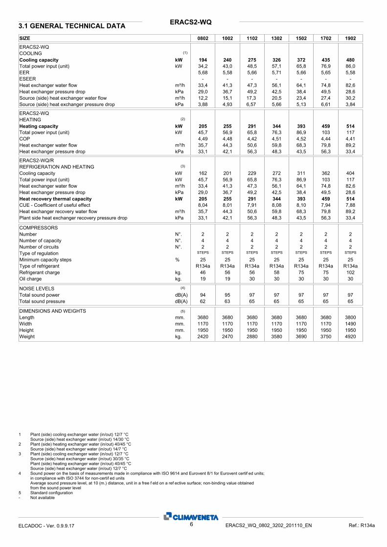
3. Technical data 3.1 General technical data
4. Operating range 5. Hydraulic data
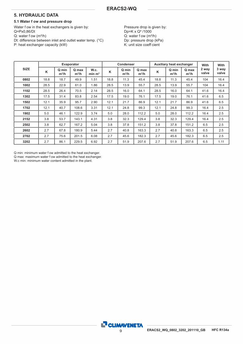
5.1 Water fl ow and pressure drop 6. Electrical data 7. Full load sound level 8. Dimensional drawings 9. Legend of pipe connections 10. Condensation control devices 11. Variable fl ow system (optional) 12. Hydraulic connections recommended
Liability disclaimerThis bulletin is not exhaustive about: installation, use, safety precautions, handling and transport. Refer to “General Manual for Installation” for further informations.This bulletin refers to standard executions, in particular for di-mension, weight, electric, hydraulic, aeraulic and refrigerant connections (whereas applicable). Contact Climaveneta Com-mercial Offi ce for further drawings and schemes.
Climaveneta declines any liability derived from the bulletin’s use.This bulletin is of exclusive property of Climaveneta, and all forms of copy are prohibited.The data contained herein are subject to variation without no-tice.
Company quality system certifi ed to UNI EN ISO 9001
and environmental certifi cation UNI EN ISO 14001
III ERACS2_WQ_0802_3202_201110_EN
ERACS2-WQ
HFC R134a
The ERACS2-WQ series multi-use units are able to simultane-ously meet hot and cold water production requests and are thus a valid alternative to traditional systems based on chill-ers and boilers for applications such as offi ce blocks, pools and shopping centres.The advanced control logic, developed by Climaveneta, en-sures that heating and cooling loads are perfectly met. When these are simultaneous, the unit exchanges evaporation and condensation heat with the system cooling and heating circuits respectively. When heat loads are not balanced or one of the two are missing, the unit automatically switches to a third heat source which can be air or water according to the model.The ERACS2-WQ units are ideal for indoor installation. For these products, heat is exchanged on the source side by a shell & tube exchanger that acts as a condenser or evaporator according to machine conditions. The heat source is made up of natural resources such as surface water basins or bore hole water associated with geothermal systems.
1. PRODUCT PRESENTATION
1.2 Energy savingEnergy saving guaranteed by the advanced operation’s logic. The best operation mode is set completely automatically and independently by the unit’s controller, in order to minimize the absorbed energy whatever the cooling and/or heating demand might be.
1.3 Extensive range of operationSupply of hot water in use up to 55°C, offering maximum versatil-ity with respect to different plant engineering solutions.
1.4 Integrated condensing controlA pressostatic valve is supplied as standard for the condensation control. Under request is available even a 3-way valve option, for all the applications in which a constant waterfl ow is assumed to be on the condenser.
1.1 Unique proposalUnit designed to satisfy the cold and the hot side requirements simultaneously, for 4-pipe systems without any particular opera-tion mode setting.
IV ERACS2_WQ_0802_3202_201110_EN
ERACS2-WQ
HFC R134a
Perfect functionality of Climaveneta units is guaranteed by ac-curate tests carried out along the productive process, and by fi nal test of every unit at the end of the work cycle, as imposed by ISO9001. Climaveneta also offers clients the chance to require and wit-ness additional performance and sound level tests be per-formed; highly skilled technical crew follow these operations in detail, to ensure maximum satisfaction of the customer. For units of the ERACS series Climaveneta offers the possibility to conduct visionati or presenziati tests.
Running tests are standard tests similar to those normally conducted at the productive unit that the client can observe without participation.
Witness tests are extra tests that the client can observe and during which can request clarifi cations upon modalities or work conditions of the unit, receiving test reports at the end. Witness tests can include sound level and performance tests.
Acoustical tests allow to verify levels of sound emissions of the unit; tests are performed repeating measurements of sound pressure in determined points, positioned on an ideal grid with walls 1 meter distance from the unit panels. For every measur-ing point a spectrum in octave band for sound pressure and the average value is supplied to the customer. Then the average global values for pressure at 1 meter, according to ISO3744, and the average sound power, referred to the whole unit, are counted.
Performance tests are based on the measurement of electric data, water fl ow, working temperature, electric power absorbed, and capacity delivered. Measurements can be made at one or three work points while varying the outlet temperatures of the evaporator and condens-er conditions. At the clients discretion, performance tests can be conducted under full or part load conditions for every operat-ing mode possible for the unit. Full load tests conducted in one or three work points permit two further personalized versions: • with a mixture of ethyl glycol water in the heat exchanger; • up to the maximum working temperature of the heat exchang-er on the source side.
Part load tests can be conducted using two different load par-tialization methods: the fi rst one requires to reduce the active resources’ number, while second one requires to modulate load on each resource. At part load the unit can be tested just in one working point.
The following two tests can always be requested during fi nal testing:• Simulation of the most common alarm states• Measurement of pressure drop of exchanger on hydraulic circuit side
1.5 Tests
1 ERACS2_WQ_0802_3202_201110_EN
ERACS2-WQ
HFC R134a
Multi-purpose indoor unit for use in 4-pipe systems for the si-multaneous production of chilled and hot water by means of two independent water circuits. These units are able to satisfy the demand for hot and cold water simultaneously through a system that does not require seasonal switching. Each circuit works with a semi-hermetic screw compressor using R134a, and three tube nest heat exchangers, a cold exchanger on the user side shared by both circuits that acts as an evaporator in the production of cold water, a heat exchanger on the user side that words as a condenser in the production of hot water, and a source side exchanger that works as either condenser or evaporator as required by the loads.
2.2 Standard unit composition FrameFrame in polyester-painted galvanized steel. The self-support-ing frame is built to guarantee maximum accessibility for servic-ing and maintenance operations.
Refrigerant circuitThe unit has two completely independent cooling circuits in or-der to ensure continuous operation, limited pollution, and easy maintenance. Each cooling circuit is fi tted as standard with:
externally equalised thermostat valve• safety valves and high and low pressure transducers• check valve on the compressor delivery line• on-off cock on the compressor delivery line and refrigerant • linesolenoid valve on the refrigerant line• dryer fi lter with replaceable cartridge• refrigerant line sight glass with humidity indicator• high-pressure safety pressure-switch. •
Screw compressorsSemi-hermetic screw compressors with 2 fi ve- and six-lobe ro-tors: the fi ve-lobe rotor is splined directly onto the motor with-out the use of interposed overgears. The use of the two rotors permits elevated volumetric output, uniform gas fl ow without pulsation, and reduced vibration and dimensions. The bearings provided along the rotor axis in a separate chamber isolated from the compression chamber are made in carbon steel. The insertion of an economiser between the source-side heat ex-changer and the cold exchanger on the user side permits in-creased cooling output and EER. Each compressor is provided with an inlet for the injection of refrigerant (for the extension of operating limits) and the use of the economiser. Lubrication is forced without using an oil pump; the built-in oil separator has 3 stages of separation, and a 10 mm stainless steel mesh fi lter ensures the constant presence of oil inside. Cooling power is partialised by a slide valve, which depending on the position assumed, permits compression chamber reduction by steps; each compressor can therefore deliver 100%, 75% and 50% of its capacity.
The two pole motors with 2950 rpm rotation speed are fi tted with electric devices that limit the current absorbed during com-pressor start-up and empty start-up, both of which are preset as standard. Each compressor is fi tted with manual-reset motor thermal protection, delivery gas temperature control, oil level check, and an electric resistance for the heating of the sump when the compressor is stopped. A check valve fi tted on the refrigerant delivery line prevents the rotors from reversing after stopping. On-off cocks on the delivery line of each compressor can cut off the supply of refrigerant gas to the exchangers when required.
Plant -side cold heat exchangerThe direct expansion type tube nest exchanger acts as an evaporator with refrigerant fl ow on the tube nest side and wa-ter fl ow on the shell side. The tubes have asymmetrical fl ows that maintain the correct speed of the refrigerant in the tubes when passing from the liquid phase into steam. The water fl ow on the shell side is fi tted with baffl es to increase turbulence and therefore the effi ciency of exchange. The steel shell has external foamed closed-cell elastomer insulating lining 10 mm thick and thermal conductivity of 0.033 W/mK at 0°C. The tube nest is manufactured using copper tubes with internal grooves for favouring heat exchange and mechanically expanded onto the tube plates. The heat exchanger is fi tted with a differential pressure switch which controls the fl ow of water when the unit is working, in this way preventing the formation of ice inside. The heat exchanger is made in compliance with PED standard work pressure requisites.
Plant -side hot heat exchanger The tube nest heat exchanger acts as a condenser with re-frigerant fl ow on the tube nest side and water fl ow on the shell side. The tubes have asymmetrical fl ows that maintain the cor-rect speed of the refrigerant in the tubes when passing from the liquid phase into steam. The water fl ow on the steel shell side is fi tted with baffl es to increase turbulence and therefore the effi ciency of exchange. The tube nest is manufactured us-ing copper tubes with internal grooves for favouring heat ex-change and mechanically expanded onto the tube plates. The heat exchanger is fi tted with a differential pressure switch which controls the fl ow of water when the unit is working, in this way preventing anomalies and overheating. The heat exchanger is made in compliance with PED standard requisites for work pressure.
Source -side heat exchanger The tube nest heat exchanger guarantees the energy balance in the circuit whenever the heat and cold loads have different values and therefore acts as either evaporator or condenser as required, with refrigerant fl ow on the tube nest side and water fl ow on the shell side. The tubes have asymmetrical fl ows that maintain the correct speed of the refrigerant in the tubes when passing from the liquid phase into steam. The steel shell has external foamed closed-cell elastomer insulating lining 10 mm thick and thermal conductivity of 0.033 W/mK at 0°C. The tube nest is manufactured using copper tubes with internal grooves for favouring heat exchange and mechanically expanded onto the tube plates. The heat exchanger is fi tted with a differential pressure switch which controls the fl ow of water when the unit is working, in this way preventing the formation of ice inside. Condensation control is ensured by a 2-way modulation valve that adjusts the fl ow of water inside the exchanger (see dedi-cate section).
Electric power and control power Electric power and control panel compliant with EN 60204-1/ IEC 204-1, complete with:
electronic controller• transformer for control circuit• general door lock isolator• power circuit with bar distribution system• fuses and contactors for compressors• terminals for cumulative alarm block• remote ON/OFF terminals• spring-type control circuit terminal boards• phase sequence relays. •
2. UNIT DESCRIPTION2.1 Units for 4 pipes-systems water source
2 ERACS2_WQ_0802_3202_201110_EN
ERACS2-WQ
HFC R134a
2.3 Certifi cation CE - Product quality certifi cate for the European Union • GOST - Product quality certifi cate for Russian Federation • SAFETY QUALITY LICENCE - Product quality certifi cate for • Popular Republic of ChinaM&I - Product quality certifi cate for Australia and New Zea-• land Machine directive 2006/42/CE • PED directive 97/23/EC • Low Voltage directive 2006/95/EC • ElectroMagnetic compatibility directive 2004/108/EC• ISO 9001 - Company´s Quality Management System certifi ca-• tionISO 14001 - Company´s Environmental Management System • certifi cation
2.4 Unit´s testsTesting is conducted throughout the productive process using the procedures specifi ed in ISO9001. Both performance and sound tests can be performed in the presence of the client upon payment. Performance tests consist in the measurement of elec-tric data, water fl ows, work temperature, absorbed power and power output under both full and partial load conditions. During performance tests, the main alarm states can be simulated and the pressure drops in the exchangers can be measured. Sound tests permit the verifi cation of the sound power level radiated by the unit and provide the client with the sound pressure spec-trum in octave bands, the average sound pressure level, and its average global sound pressure values at a distance of 1 meter, and the sound power produced by the entire unit.
2.5 Electronic control W3000SE Large The controller W3000 large offers the latest control and func-tions specially developed for these units. The keypad is generously sized with full operating status dis-play. The controls and detailed LCD make access to machine settings easy and safe. These resources permit to diirectly act on the unit settings through a multilevel menu, available in sev-eral languages. The diagnostics includes full management of alarms with black-box functions and alarm record for better analysis of unit per-formance. For multi-units plants a special device to coordinate and man-age all the resources is available as an option; energy meter-ing device is even possible as an option. Supervision is easy through Climaveneta devices or with various options for inter-facing to ModBus, Bacnet, Echelon LonTalk protocols.Compatibility with remote keyboard (management up to 10 units). Clock available with programming of operation (standard 4 days and 10 time bands).Temperature regulation managed on the two water circuits, with a proportional logic referred to the return water temperatures. This allows to satisfy simultaneously the different heating- and cooling requests, with no need of mode changeover.
3 ERACS2_WQ_0802_3202_201110_EN
ERACS2-WQ
HFC R134a
2.6 Accessories
ACCESSORIES DESCRIPTION BENEFIT
Soft start Electronic device adopted to manage the inrush current.Break down of the inrush current as soon as the electri-cal motor is switch on, lower motor's mechanical wear, favourable sizing for the electrical system.
Electronic expansion valve (only cooling)
Electronic lamination device wtih step motor. It is designed for the continuous and precise control of refrigerant fl ow entering in the evaporator. This solution permits extremely short times for reaction to variation in load, optimising power consumption.
Integral acoustic enclo-sure basic
Enclosure realized with peraluman panels lined with an acoustic insulation made by polyester fi ber of thickness 30 mm. The sound power level reduction achieved with this accessory is 14 dB(A).
Integral acoustic enclo-sure plus
Enclosure realized with peraluman panels lined with a special acoustic insulation composed by 5 alternating layers of polyurethane and gaiter of total thickness 50 mm. The sound power level reduction achieved with this accessory is 18 dB(A).
3 way-valve for the condensing pressure control (see dedicate section)
3 way modulating valve in grey cast iron with diverting function. The valve is selected and tested by Climaveneta during the unit's test. Recommended for geo-thermal appli-cations, in which constant waterfl ow is necessary. (Separate-ly supplied, not mounted)
VPF system (see dedi-cate section)
Predisposition for the variable fl ow pumps' control on the primary circuit/s. The system comprises: extensions on the controller to read the system's pressure transducer signals (4-20 mA) and the consequent management of pumps and bypass valve (0-10 V signal), additional pressure transducer as extra safety device. [Pressure transducer, pumps and bypass valve at client responsability]
Energy consumption associated with fl uid circulation drops signifi cantly, very often over 50%. Beyond the energy saving and the consequent lower operating costs, this new approach enables simplifi cation in the plant's design that ensures substantial savings in initial investment costs. The integration of variable fl ow pumps on board, permits signifi cant savings in overall dimensions, circuit components and in the system's commissioning.
Compressors' on/off signal Auxiliary contacts providing a voltage-free signal Allows remote signalling of compressor's activation or
remote control of any auxiliary loads.
ModBUS connectivity Interface module for ModBUS protocols Allows integration with BMS operating with ModBUS protocol
BACnet connectivity Interface module for BACnet protocols Allows integration with BMS operating with BACnet protocol
Echelon connectivity Interface module for Echelon systems Allows integration with BMS operating with LonWorks procotls
Auxiliary signal 4-20mA4..20mA analogue input. Allows to change the operating set-point according to the value of current applied to the analogue input
Enforce Energy Saving policies
Automatic circuit breakers Over-current switch on the major electrical loads. It protects compressors and/or fans from possible
current peaks.
Input remote Demand Limit Digital input (voltage free) It permits to limit the unit's power absorption for safety
reasons or in temporary situation.
Numbered cables on electrical boardRemote signal double set-point Allows to activate the Energy Saving set-point Enforce Energy Saving policy
Evaporator fl owswitch (water side)Container packingRubber anti vibration device
DEMETRA (see dedica-ted manual)
Software to monitor capacity and energy absorbed by the units.
Allows a dynamic monitoring of the installed units and therefore a data (hourly based) downloading to sup-port the current needs of energy management.
Group regulation device (see dedicate section)
Supervisory device (see dedicate section)
4 ERACS2_WQ_0802_3202_201110_EN
ERACS2-WQ
HFC R134a
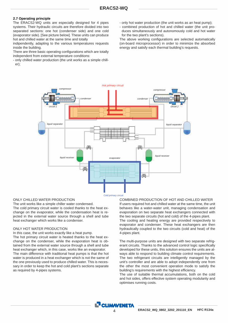
2.7 Operating principle The ERACS2-WQ units are especially designed for 4 pipes systems. Their hydraulic circuits are therefore divided into two separated sections: one hot (condenser side) and one cold (evaporator side). [See picture below]. These units can produce hot and chilled water at the same time and totallyindipendently, adapting to the various temperatures requests inside the building.There are three basic operating confi gurations which are totally independent from external temperature conditions:- only chilled water production (the unit works as a simple chill-
er);
- only hot water production (the unit works as an heat pump);- combined production of hot and chilled water (the unit pro-
duces simultaneously and autonomously cold and hot water for the two plant’s sections).
The above working confi gurations are selected automatically (on-board microprocessor) in order to minimize the absorbed energy and satisfy each thermal building’s requests.
ONLY CHILLED WATER PRODUCTIONThe unit works like a simple chiller water condensed.The cold primary circuit water is cooled thanks to the heat ex-change on the evaporator, while the condensation heat is re-jected in the external water source through a shell and tube heat exchanger which works like a condenser.
ONLY HOT WATER PRODUCTIONIn this case, the unit works exactly like a heat pump.The hot primary circuit water is heated thanks to the heat ex-change on the condenser, while the evaporation heat is ob-tained from the external water source through a shell and tube heat exchanger which, in this case, works like an evaporator.The main difference with traditional heat pumps is that the hot water is produced in a heat exchanger which is not the same of the one previously used to produce chilled water. This is neces-sary in order to keep the hot and cold plant’s sections separate as required by 4-pipes systems.
COMBINED PRODUCTION OF HOT AND CHILLED WATERIf users required hot and chilled water at the same time, the unit behaves like a water-water unit, managing condensation and evaporation on two separate heat exchangers connected with the two separate circuits (hot and cold) of the 4-pipes plant.The cooling and heating energy are provided respectively to evaporator and condenser. These heat exchangers are then hydraulically coupled to the two circuits (cold and heat) of the 4-pipes plant.
The multi-purpose units are designed with two separate refrig-erant circuits. Thanks to the advanced control logic specifi cally developed for these units, this solution ensures the units are al-ways able to respond to building climate control requirements. The two refrigerant circuits are intelligently managed by the unit’s controller and are able to adopt independently one from the other the most convenient operation mode to satisfy the building’s requirements with the highest effi ciency.The use of suitable thermal accumulations, both on the cold and hot sides, offers effective system operating modularity and optimises running costs.
Hot primary circuit
condenser
compressor
circuit 1
liquid separator
liquid receiver evaporatorliquid receiver
liquid separator
circuit 2
compressor
condenser
Cold primary circuit
5 ERACS2_WQ_0802_3202_201110_EN
ERACS2-WQ
HFC R134a
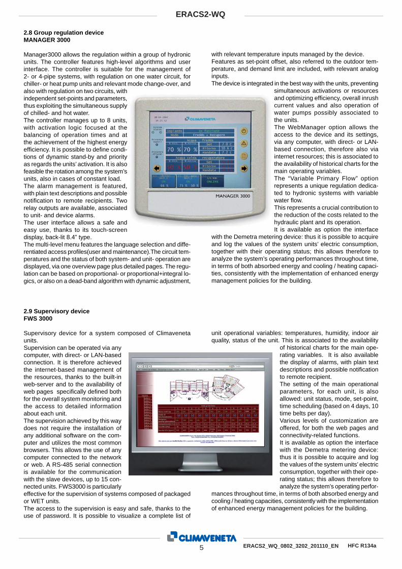
2.8 Group regulation device MANAGER 3000
Manager3000 allows the regulation within a group of hydronic units. The controller features high-level algorithms and user interface. The controller is suitable for the management of 2- or 4-pipe systems, with regulation on one water circuit, for chiller- or heat pump units and relevant mode change-over, and also with regulation on two circuits, with independent set-points and parameters, thus exploiting the simultaneous supply of chilled- and hot water. The controller manages up to 8 units, with activation logic focused at the balancing of operation times and at the achievement of the highest energy effi ciency. It is possible to defi ne condi-tions of dynamic stand-by and priority as regards the units’ activation. It is also feasible the rotation among the system’s units, also in cases of constant load. The alarm management is featured, with plain text descriptions and possible notifi cation to remote recipients. Two relay outputs are available, associated to unit- and device alarms. The user interface allows a safe and easy use, thanks to its touch-screen display, back-lit 8.4” type. The multi-level menu features the language selection and diffe-rentiated access profi les(user and maintenance).The circuit tem-peratures and the status of both system- and unit- operation are displayed, via one overview page plus detailed pages. The regu-lation can be based on proportional- or proportional+integral lo-gics, or also on a dead-band algorithm with dynamic adjustment,
2.9 Supervisory device FWS 3000
Supervisory device for a system composed of Climaveneta units. Supervision can be operated via any computer, with direct- or LAN-based connection. It is therefore achieved the internet-based management of the resources, thanks to the built-in web-server and to the availability of web pages specifi cally defi ned both for the overall system monitoring and the access to detailed information about each unit. The supervision achieved by this way does not require the installation of any additional software on the com-puter and utilizes the most common browsers. This allows the use of any computer connected to the network or web. A RS-485 serial connection is available for the communication with the slave devices, up to 15 con-nected units. FWS3000 is particularly effective for the supervision of systems composed of packaged or WET units. The access to the supervision is easy and safe, thanks to the use of password. It is possible to visualize a complete list of
with relevant temperature inputs managed by the device. Features as set-point offset, also referred to the outdoor tem-perature, and demand limit are included, with relevant analog inputs. The device is integrated in the best way with the units, preventing
simultaneous activations or resources and optimizing effi ciency, overall inrush current values and also operation of water pumps possibly associated to the units. The WebManager option allows the access to the device and its settings, via any computer, with direct- or LAN-based connection, therefore also via internet resources; this is associated to the availability of historical charts for the main operating variables. The “Variable Primary Flow” option represents a unique regulation dedica-ted to hydronic systems with variable water fl ow. This represents a crucial contribution to the reduction of the costs related to the hydraulic plant and its operation.It is available as option the interface
with the Demetra metering device: thus it is possible to acquire and log the values of the system units’ electric consumption, together with their operating status; this allows therefore to analyze the system’s operating performances throughout time, in terms of both absorbed energy and cooling / heating capaci-ties, consistently with the implementation of enhanced energy management policies for the building.
unit operational variables: temperatures, humidity, indoor air quality, status of the unit. This is associated to the availability
of historical charts for the main ope-rating variables. It is also available the display of alarms, with plain text descriptions and possible notifi cation to remote recipient. The setting of the main operational parameters, for each unit, is also allowed: unit status, mode, set-point, time scheduling (based on 4 days, 10 time belts per day). Various levels of customization are offered, for both the web pages and connectivity-related functions.It is available as option the interface with the Demetra metering device: thus it is possible to acquire and log the values of the system units’ electric consumption, together with their ope-rating status; this allows therefore to analyze the system’s operating perfor-
mances throughout time, in terms of both absorbed energy and cooling / heating capacities, consistently with the implementation of enhanced energy management policies for the building.
Total sound power dB(A) 94 95 97 97 97 97 976565 656362dB(A)Total sound pressure 6565
DIMENSIONS AND WEIGHTS (5)
Length Width Height Weight
mm.mm.mm.kg.
3680117019502420
3680117019502470
3680117019502880
3680 1170 1950 3580
3680 1170 1950 3690
3680117019503750
3800149019504920
1 Plant (side) cooling exchanger water (in/out) 12/7 °C Source (side) heat exchanger water (in/out) 14/30 °C 2 Plant (side) heating exchanger water (in/out) 40/45 °C Source (side) heat exchanger water (in/out) 14/7 °C 3 Plant (side) cooling exchanger water (in/out) 12/7 °C Source (side) heat exchanger water (in/out) 30/35 °C Plant (side) heating exchanger water (in/out) 40/45 °C Source (side) heat exchanger water (in/out) 12/7 °C 4 Sound power on the basis of measurements made in compliance with ISO 9614 and Eurovent 8/1 for Eurovent certif ed units; in compliance with ISO 3744 for non-certif ed units Average sound pressure level, at 10 (m.) distance, unit in a free f eld on a ref ective surface; non-binding value obtained from the sound power level 5 Standard configuration - Not available
Total sound power dB(A) 98 99 99 99 99 67 676766dB(A)Total sound pressure 67
DIMENSIONS AND WEIGHTS (5)
Length Width Height Weight
mm.mm.mm.kg.
3800149019505310
3800149019505730
5000149020506470
5000 1490 2050 6590
5000 1490 2050 7370
1 Plant (side) cooling exchanger water (in/out) 12/7 °C Source (side) heat exchanger water (in/out) 14/30 °C 2 Plant (side) heating exchanger water (in/out) 40/45 °C Source (side) heat exchanger water (in/out) 14/7 °C 3 Plant (side) cooling exchanger water (in/out) 12/7 °C Source (side) heat exchanger water (in/out) 30/35 °C Plant (side) heating exchanger water (in/out) 40/45 °C Source (side) heat exchanger water (in/out) 12/7 °C 4 Sound power on the basis of measurements made in compliance with ISO 9614 and Eurovent 8/1 for Eurovent certif ed units; in compliance with ISO 3744 for non-certif ed units Average sound pressure level, at 10 (m.) distance, unit in a free f eld on a ref ective surface; non-binding value obtained from the sound power level 5 Standard configuration - Not available
Limits to exchanger water temperature are valid within the minimum - maximum water f ow range indicated in the Hydraulic Data section.
(1) Condenser water temp. 30/35 °C(2) Evaporator water (in/out) 12/7 °C
(3) With temperatures down to -8°C use anti-freeze mixtures. In case of lower temperatures, please contact our Sales Department.(4) Valid for temperature of f uid the evaporator >= -3°C. In case of lower temperatures, please contact our Sales Department.
ETHYLENE GLYCOL MIXTURE
Ethylene glycol and water mixtures, used as a heat-conveying f uid, cause a variation in unit performance. For correct data, use the factors indicated in the following table.
Freezing point (°C)
0 -5 -10 -15 -20 -25 -30 -35
Ethylene glycol percentage by weight
0 12% 20% 30% 35% 40% 45% 50%
cPf 1 0,985 0,98 0,974 0,97 0,965 0,964 0,96
cQ 1 1,02 1,04 1,075 1,11 1,14 1,17 1,2
cdp 1 1,07 1,11 1,18 1,22 1,24 1,27 1,3
cPf: cooling capacity correction factorcQ: f ow correction factorcdp: pressure drop correction factor
For data concerning other kind of anti-freeze solutions (e.g. propylene glycol) please contact our Sales Department.
Performances are based on clean condition of tubes (fouling factor =1). For different fouling values, performance should be adjusted using the correction factors shown in the following ta-ble.
f1 - f2 : capacity correction factorsfk1 - fk2 : compressor power input correction factorsfx1 - fx2 : total power input correction factors
4. OPERATING RANGE
8 ERACS2_WQ_0802_3202_201110_GB
ERACS2-WQ
HFC R134a
SIZEEvaporator Condenser Auxiliary heat exchanger With
Water f ow in the heat exchangers is given by:Q=Px0,86/DtQ: water f ow (m³/h)Dt: difference between inlet and outlet water temp. (°C)P: heat exchanger capacity (kW)
Pressure drop is given by:Dp=K x Q² /1000Q: water f ow (m³/h)Dp: pressure drop (kPa)K: unit size coeff cient
Q min: minimum water f ow admitted to the heat exchanger.Q max: maximum water f ow admitted to the heat exchanger.W.c min: minimum water content admitted in the plant.
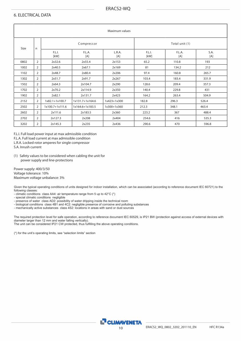
F.L.I. Full load power input at max admissible conditionF.L.A. Full load current at max admissible conditionL.R.A. Locked rotor amperes for single compressorS.A. Inrush current
(1) Safety values to be considered when cabling the unit for power supply and line-protections
Power supply: 400/3/50Voltage tolerance: 10%Maximum voltage unbalance: 3%
6. ELECTRICAL DATA
10 ERACS2_WQ_0802_3202_201110_EN
ERACS2-WQ
HFC R134a
Given the typical operating conditions of units designed for indoor installation, which can be associated (according to reference document IEC 60721) to the following classes: - climatic conditions class AA4: air temperature range from 5 up to 42°C (*) - special climatic conditions negligible - presence of water class AD2: possibility of water dripping inside the technical room - biological conditions class 4B1 and 4C2: negligible presence of corrosive and polluting substances - mechanically active substances class 4S2: locations in areas with sand or dust sources The required protection level for safe operation, according to reference document IEC 60529, is IP21 BW (protection against access of external devices with diameter larger than 12 mm and water falling vertically). The unit can be considered IP21 CW protected, thus fulfilling the above operating conditions. (*) for the unit’s operating limits, see “selection limits” section
ERACS2-WQ7. FULL LOAD SOUND LEVEL
SIZE Octave band [Hz] 20001000 500 250 125 63 80004000
Plant (side) cooling exchanger water (in/out) 12/7 °CSource (side) heat exchanger water (in/out) 14/30 °C Sound power on the basis of measurements made in compliance with ISO 9614 and Eurovent 8/1 for Eurovent certif ed units; in compliance with ISO 3744 for non-certif ed units Such certification refers specifically to the sound Power Level in dB(A). This is therefore the only acoustic data to be considered as binding.
Working conditions
SIZE Octave band [Hz] at 10 m20001000 500 250 125 63 80004000
Plant (side) cooling exchanger water (in/out) 12/7 °CSource (side) heat exchanger water (in/out) 14/30 °C Average sound pressure level, at 10 (m.) distance, unit in a free f eld on a ref ective surface; non-binding value obtained from the sound power level. Additional soundproofing The sound power and pressure levels are reduced of 14 dB(A) when present the accessory “integral acoustical enclosure basic”and of 18 dB(A) when present the accessory “integral acoustical enclosure plus”.
For installation purposes, please refer to the documentation sent after the purchase-contract. This technical data should be considered as indicative. CLIMAVENETA may modify them at any moment.
Size
DIMENSIONS AND WEIGHTSERACS2-WQ
A[mm]
B[mm]
H[mm]
P[kg]
0802 3680 1170 1950 2420
1002 3680 1170 1950 2470
1102 3680 1170 1950 2880
1302 3680 1170 1950 3580
1502 3680 1170 1950 3690
1702 3680 1170 1950 3750
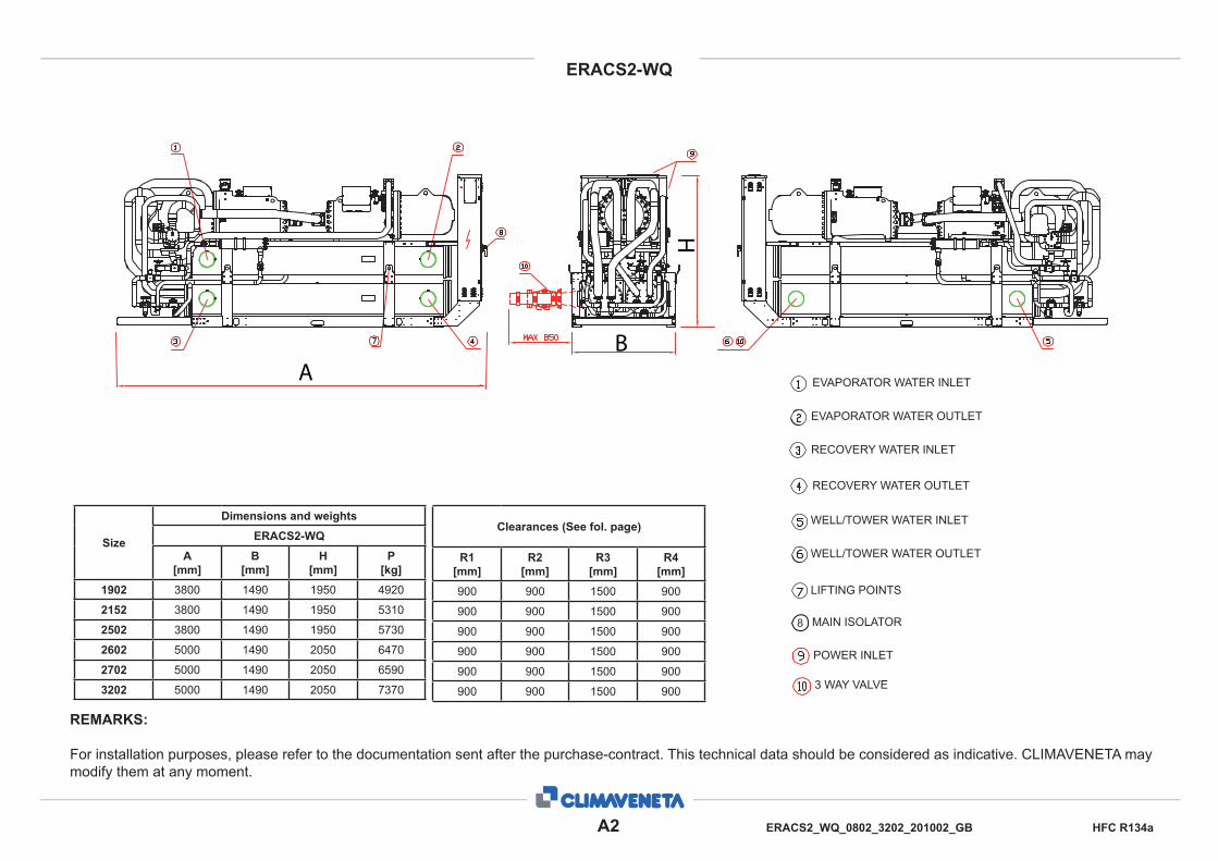
8. DIMENSIONAL DRAWINGS
CLEARANCES (See fol. page)
R1[mm]
R2[mm]
R3[mm]
R4[mm]
500 500 800 500
500 500 800 500
500 500 800 500
500 500 800 500
500 500 800 500
500 500 800 500
EVAPORATOR WATER INLET
EVAPORATOR WATER OUTLET
RECOVERY WATER INLET
RECOVERY WATER OUTLET
WELL/TOWER WATER INLET
WELL/TOWER WATER OUTLET
MAIN ISOLATOR HANDLER
POWER INLET
ERACS2-WQ
A2 ERACS2_WQ_0802_3202_201002_GB HFC R134a
REMARKS:
For installation purposes, please refer to the documentation sent after the purchase-contract. This technical data should be considered as indicative. CLIMAVENETA may modify them at any moment.
Size
Dimensions and weightsERACS2-WQ
A[mm]
B[mm]
H[mm]
P[kg]
1902 3800 1490 1950 4920
2152 3800 1490 1950 5310
2502 3800 1490 1950 5730
2602 5000 1490 2050 6470
2702 5000 1490 2050 6590
3202 5000 1490 2050 7370
EVAPORATOR WATER INLET
EVAPORATOR WATER OUTLET
RECOVERY WATER INLET
RECOVERY WATER OUTLET
WELL/TOWER WATER INLET
WELL/TOWER WATER OUTLET
LIFTING POINTS
MAIN ISOLATOR
Clearances (See fol. page)
R1[mm]
R2[mm]
R3[mm]
R4[mm]
900 900 1500 900
900 900 1500 900
900 900 1500 900
900 900 1500 900
900 900 1500 900
900 900 1500 900
AB
H
POWER INLET
3 WAY VALVE
ERACS2-WQ
A3 ERACS2_WQ_0802_3202_201002_GB HFC R134a
INSTRUCTIONS:
- Make sure that all the panels are f rmly f xed in place before moving the unit.- Before lifting it, check the weight on the CE label.- Use all, and only, the lifting points provided,
- Use slings of equal length,- Use a spread-bar (not included)- Move the unit carefully and avoid abrupt movements.
R1
R2
R3
R4
SUPPORTING BASEMENT
Warning: Electrical power!
ERACS2-WQ
A4 ERACS2_WQ_0802_3202_201002_GB HFC R134a
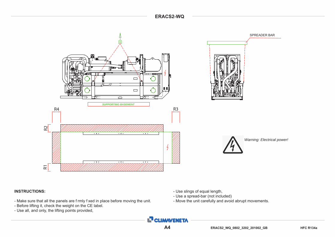
INSTRUCTIONS:
- Make sure that all the panels are f rmly f xed in place before moving the unit.- Before lifting it, check the weight on the CE label.- Use all, and only, the lifting points provided,
- Use slings of equal length,- Use a spread-bar (not included)- Move the unit carefully and avoid abrupt movements.
Warning: Electrical power!
R4 R3
R2R1
SPREADER BAR
SUPPORTING BASEMENT
ERACS2-WQ
A5 ERACS2_WQ_0802_3202_201002_GB HFC R134a
EVAPORATOR CONDENSER RECOVERY
WATER INLET WATER OUTLET WATER INLET WATER OUTLET WATER INLET WATER OUTLET
ø ø WITHOUT VALVES 2 WAY VALVE ø 3 WAY VALVE ø WITHOUT VALVES 2 WAY VALVE ø 3 WAY VALVE ø ø ø
0802 UNI ISO 228/1 G 4 B (#) UNI ISO 228/1 G 4 B (#) - DN 50 DN 80 - DN 50 DN 80 UNI ISO 228/1 G 4 B (#) UNI ISO 228/1 G 4 B (#)
1002 UNI ISO 228/1 G 4 B (#) UNI ISO 228/1 G 4 B (#) - DN 50 DN 80 - DN 50 DN 80 UNI ISO 228/1 G 4 B (#) UNI ISO 228/1 G 4 B (#)
1102 UNI ISO 228/1 G 4 B (#) UNI ISO 228/1 G 4 B (#) - DN 65 DN 80 - DN 65 DN 80 UNI ISO 228/1 G 4 B (#) UNI ISO 228/1 G 4 B (#)
Pipe threads where pressure-tight joints are not made on the threads - Designation, dimensions and tolerances
Used terminology: G: Pipe threads where pressure-tight joints are not made on the
threadsA: Close tolerance class for external pipe threads where pres-
sure tight joints are not made on the threadsB: Wider tolerance class for external pipe threads where pres-
sure tight joints are not made on the threads
Internal threads: G letter followed by thread mark (only tolerance class)External threads: G letter followed by thread mark and by A let-
ter for A class external threads or by B letter for B class external threads
UNI ISO 7/1
Pipe threads where pressure-tight joints are made on the threads - Designation, dimensions and tolerances
Used terminology: Rp: Internal cylindrical threads where pressure-tight joints are
made on the threadsRc: Internal conical threads where pressure-tight joints are
made on the threadsR: External conical threads where pressure-tight joints are
made on the threadsInternal cylindrical threads: R letter followed by p letterInternal conical threads: R letter followed by c letterExternal conical threads: R letter
Designation Description
UNI ISO 7/1 - Rp 1 1/2Internal cylindrical threads where pressure-tight joints are made on the threads, def ned by stand-ard UNI ISO 7/1Conventional ø: 1 1/2”
UNI ISO 7/1 - Rp 2 1/2Internal cylindrical threads where pressure-tight joints are made on the threads, def ned by stand-ard UNI ISO 7/1 Conventional ø: 2 1/2”
UNI ISO 7/1 - Rp 3Internal cylindrical threads where pressure-tight joints are made on the threads, def ned by stand-ard UNI ISO 7/1 Conventional ø: 3”
UNI ISO 7/1 - R 3External conical threads where pressure-tight joints are made on the threads, def ned by standard UNI ISO 7/1 Conventional ø: 3”
UNI ISO 228/1 - G 4 B
Internal cylindrical threads where pressure-tight joints are not made on the treads, def ned by standard UNI 228/1B tolerance class for external pipe threads Conventional ø: 4”
Conventional diameter value [in inches] identif es short threaddesignation, based upon the relative standard.All relative values are def ned by standards.As example, here below some values:
UNI ISO 7/1 UNI ISO 228/1Conventional ø 1” 1”
Pitch 2.309 mm 2.309 mm
External ø 33.249 mm 33.249 mm
Core ø 30.291 mm 30.291 mm
Thread height 1.479 mm 1.479 mm
09. LEGEND OF PIPE CONNECTIONS
A6 ERACS2_WQ_0802_3202_201110_GB
ERACS2-WQ
HFC R134a
10. CONDENSATION CONTROL DEVICES
Two way servo-motorized valve with steel body . The valve is selected for a thermical drop of 15°C and tested by Climavene-ta during the unit’s test. recommended for applications with un-derground and superf cial water, where it’s better to work with inverter pumps and modulation of the extracted water f ow.
Pressure drop is given by:Dp= K x Q2/1000Q: water f ow (m3/h)Dp: pressure drop (kPa)K: unit size ratio
2 WAY VALVE
SizeDT 15 °C
K
0802 104
1002 104
1102 41,6
1302 41,6
1502 41,6
1702 16,4
1902 16,4
2152 16,2
2502 6,50
2602 6,50
2702 6,50
3202 6,50
3 way modulating valve in grey cast iron with diverting function. The valve is selected for a thermic drop of 5°C and tested by Climaveneta during the unit’s test. Recommended for geo-ther-mal applications, in which constant waterf ow is necessary.
Pressure drop is given by:Dp= K x Q2/1000Q: water f ow (m3/h)Dp: pressure drop (kPa)K: unit size ratio
3 WAY VALVE
SizeDT 5 °C
K
0802 16,4
1002 16,4
1102 16,4
1302 6,50
1502 6,50
1702 6,50
1902 2,50
2152 2,50
2502 2,50
2602 2,50
2702 2,50
3202 1,11
B1 ERACS2_WQ_0802_3202_201110_GB
ERACS2-WQ
HFC R134a
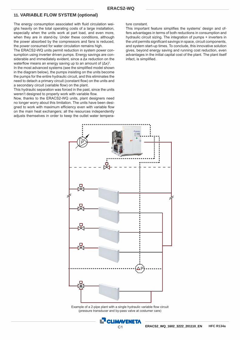
The energy consumption associated with fl uid circulation wei-ghs heavily on the total operating costs of a large installation, especially when the units work at part load, and even more, when they are in stand-by. Under these conditions, although the power absorbed by the compressors and fans is reduced, the power consumed for water circulation remains high. The ERACS2-WQ units permit reduction in system power con-sumption using inverter driven pumps. Energy savings are con-siderable and immediately evident, since a Δx reduction on the waterfl ow means an energy saving up to an amount of (Δx)3. In the most advanced systems (see the simplifi ed model shown in the diagram below), the pumps insisting on the units become the pumps for the entire hydraulic circuit, and this eliminates the need to detach a primary circuit (constant fl ow) on the units and a secondary circuit (variable fl ow) on the plant. This hydraulic separation was forced in the past, since the units weren’t designed to properly work with variable fl ow. Now, thanks to the ERACS2-WQ units, plant designers need no longer worry about this limitation. The units have been desi-gned to work with maximum effi ciency even with variable fl ow on the main heat exchangers; all the resources independently adjusts themselves in order to keep the outlet water tempera-
ture constant. This important feature simplifi es the systems’ design and of-fers advantages in terms of both reductions in consumption and hydraulic circuit sizing. The integration of pumps + inverters in the unit permits signifi cant savings in space, circuit components, and system start-up times. To conclude, this innovative solution gives, beyond energy saving and running cost reduction, even advantages in the initial capital cost of the plant. The plant itself infact, is simplifi ed.
11. VARIABLE FLOW SYSTEM (optional)
Example of a 2-pipe plant with a single hydraulic variable fl ow circuit (pressure transducer and by-pass valve at costumer care)
P
P
C1 ERACS2_WQ_1602_3222_201110_EN
ERACS2-WQ
HFC R134a
11.1 VPF systems: plants designed with a single variable fl ow hydraulic circuit
Traditional plant “Smart” plantIn this advanced solution for plant’s design, both the cold and hot circuits are variable fl ow circuits. The inverter-pumps insist on the cold and hot heat exchangers and are controlled directly by the unit’s W3000 controller.The sophisticated algorithms developed by Climaveneta allow the direct power signals coming from the plant’s pressure tran-sducer to be elaborated; this elaboration’s result is the pumps and by-pass valves control through voltage signals. The complete control of all resources (compressors, fans, pum-ps and by-pass valves) ensures the maximum system’s effi -ciency together with the highest reliability on the units.
VARIABLE FLOW SYSTEM (optional)
The two hydraulic circuits of the plant can be recognized: the hot and the cold one. In the traditional solution, both of them are hydraulically splitted in a primary constant fl ow circuit (insisting on the units) and a secondary variable fl ow circuit dedicated to the plant’s fi nal utilities. An element of the plant works to decouple the two circuits: when pumps user-side partialize according to the building’s requestes, it balances the all system by-passing the exceding fl ow to the unit.
The unit manages its own pumps as a function of its state (on/off) balancing the operating hours between them. On the other side, the plant’s inverter-pumps are managed through a differential pressure transducer: it reads the pressure drops variation on the circuit and traduce them in a power si-gnal; this signal reports the percentage of load on the building and determines the pumps’ modulation.
P
P
P
P
Example of a 4-pipe plant with two single hydraulic variable fl ow circu-its (pressure transducers and by-pass valves at costumer care)
P
P
P
P
P
P
C2 ERACS2_WQ_1602_3222_201110_EN
ERACS2-WQ
HFC R134a
VARIABLE FLOW SYSTEM (optional)
Minimum waterfl ow to technical bulletin
[m3/h]
Kvs Recommended valve Valve Valve motor ByPass
19 to 30 40 VVG41.50 DN50 SKB60 DN50 (2”)up to 37 49 VVF31.65 DN65 SKB60 DN65 (2"½)up to 60 78 VVF31.80 DN80 SKB60 DN80 (3“)up to 95 124 VVF31.90 DN100 SKC60 DN100 (4“)
up to 150 200 VVF31.91 DN125 SKC60 DN125 (5“)up to 230 300 VVF31.92 DN150 SKC60 DN150 (6”)
2-way valve and minimum recommended bypass pipe diameter as a function of the minimum waterfl ow.
The “system VPF” option comprises: - extensions on the controller to read the system’s pressure
transducer signals (4-20 mA) and the consequent manage-ment of pumps and bypass valve (0-10 V signal)
- additional pressure transducer as extra safety device.
Pumps, differential pressure transducer on the farest pipe of the plant and by-pass valve are at customer charge. Climaveneta provides only some indications for the plants de-sign, as a function of the minimum waterfl ow on the primary heat exchanger.
C3 ERACS2_WQ_1602_3222_201110_EN
ERACS2-WQ
HFC R134a
Even in that cases in which is not possible to work with a sin-gle variable primary fl ow circuits, or in that situations in which is preferible to mantain decoupled the primary circuits (to the units) and the secondary circuit (to the plants), it’s possible the primary fl ow on pumps controlled by the unit.The energy savings are lower than the solution with a unique VPF system, but still important expecially when the units are in stand-by and it’s possible to reduce the waterfl ow through the unit up to 50%.The VPF.D systems can be easily adopted in retrofi tt applica-tion, where the chiller is supposed to be replaced but not the plant.
VARIABLE FLOW SYSTEM (optional)
11.2 VPF.D systems: plants designed for variable fl ow, de-coupled, primary and secondary circuits
Traditional plant
P
P
P
P
P
P
“Smart” plant
The regulation is up to the unit’s controller, detecting the delta temperature at the primary heat exchanger: when the building’s load decreases, waterfl ow is reduced in order to mantain a fi -xed delta T between the exchangers’ inlet and outlet. The VPF.D system by Climaveneta assures even the waterfl ow balancing between primary and secondary circuit, in order to avoid the fl ow inversion in the decoupling pipe.
Example of a 4-pipe plant with cold and hot circuits hydraulically separated in a primary and a secondary ones, both of them
featuring variable fl ow
P
P
P
P
P
P
T1
T1T2
T2
The “system VPF.D” option comprises: - extensions on the controller to read the temperature probes
and to drive properly the inverter-pumps (0-10 V signal)- additional pressure transducer on the heat exchangers as
extra safety device.
The variable fl ow pumps are at customer care.
C4 ERACS2_WQ_1602_3222_201110_EN
ERACS2-WQ
HFC R134a
VARIABLE FLOW SYSTEM (optional)
Minimum waterfl ow to technical bulletin
[m3/h]
Decoupling pipe
25 to 40 2"½up to 60 3"
up to 100 4"up to 150 5"up to 225 6"up to 375 8"
Minimum decoupling pipe diameter as a function of the minimum waterfl ow
Climaveneta provides in the table below some indications for the plants design, as a function of the nominal waterfl ow on the primary heat exchanger.NOTE: temperature probes are separately supplied
C5 ERACS2_WQ_1602_3222_201110_EN
ERACS2-WQ
HFC R134a
12. HYDRAULIC CONNECTIONS RECOMMENDEDProtect the hydraulic circuit with antifreeze when shutting down a charged system for winter. If necessary, drain the water inside the exchangers. It is absolutely essential that, in the presence of dirty and/or aggressive water, an intermediate heat exchanger is placed up-
stream of the refrigeration system heat exchangers.The connecting pipes must be properly supported so as not to weigh on the unit.
12.1 Hydraulic connections with hot and cold heat exchanger plant side The following must be installed on the heat exchanger hydraulic circuit (see Fig.):
Two pressure gauges with a suitable range (inlet - outlet)• Two service cocks for the pressure gauges.• Air bleed valves to be fi tted to the highest points of the circu-• it.Two vibration damping joints (inlet - outlet) positioned hori-• zontally.One fl ow switch to be fi tted at the unit outlet in a linear stretch • of a length of about 7 times the diameter of the pipe itself. The fl ow switch must be calibrated so as to guarantee a minimum water fl ow to the heat exchangers, not less than the value indicated in the unit bulletin or declared by the supplier. If this value is not available, calibrate the fl ow switch to 70% of the rated water fl ow of the unit (not envisaged for desuperhea-ters).
A calibration valve at the outlet.• Two shut-off valves (inlet - outlet).• A mechanical fi lter with a maximum mesh size of 1 mm to be • fi tted as near as possible to the heat exchanger inletA drain cock to be fi tted in the lowest point of the hydraulic • system.A circulation pump.• All other equipment listed in Fig. •
The directions for installation set out above represent a necessary condition for the validity of the guarantee. However, Climaveneta is willing to examine any different ne-eds, which must in any case be approved before the refrigera-tion system is started up.
Climaveneta S.p.A. Via Sarson 57/c 36061 Bassano del Grappa (VI) Italy Tel +39 0424 509500 Fax +39 0424 509509 [email protected] www.climaveneta.com
Climaveneta France 3, Village d’Entreprises ZA de la Couronne des Prés Avenue de la Mauldre 78680 Epone France Tel +33 (0)1 30 95 19 19 Fax +33 (0)1 30 95 18 18 [email protected] www.climaveneta.fr
Climaveneta Deutschland Rhenus Platz, 2 59439 Holzwickede Germany Tel +49 2301 91222-0 Fax +49 2301 91222-99 [email protected] www.climaveneta.de
Climaveneta Espana - Top Clima Londres 67, 1° 4° 08036 Barcelona Spain Tel +34 963 195 600 Fax +34 963 615 167 [email protected] www.climaveneta.com
Climaveneta Chat Union Refrig. Equipment Co Ltd 88 Bai Yun Rd, Pudong Xinghuo New dev. zone 201419 Shanghai China Tel 008 621 575 055 66 Fax 008 621 575 057 97
Climaveneta Polska Sp. z o.o. Ul. Sienkiewicza 13A 05-120 Legionowo Poland Tel +48 22 766 34 55-57 Fax +48 22 784 39 09 [email protected] www.climaveneta.pl
Climaveneta India Climate Technologies (P) LTD #3487, 14th Main, HAL 2nd stage, Indiranagar, Bangalore 560008 India Tel +91-80-42466900 - 949 Fax +91-80-25203540 [email protected]