23
10/100BASE-TX TO 100BASE-FX MEDIA CONVERTERS KC-300DM Series Installation Guide DOC.060215-KC-300D
| Date post: | 30-Apr-2019 |
| Category: |
Documents |
| Upload: | trinhduong |
| View: | 221 times |
| Download: | 0 times |

-1-
10/100BASE-TX TO 100BASE-FXMEDIA CONVERTERS
KC-300DM Series
Installation Guide
DOC.060215-KC-300D

-2-
(C) 2003 KTI Networks Inc. All rights reserved. No part of this documen-tation may be reproduced in any form or by any means or used to makeany directive work (such as translation or transformation) without per-mission from KTI Networks Inc.
KTI Networks Inc. reserves the right to revise this documentation and tomake changes in content from time to time without obligation on the partof KTI Networks Inc. to provide notification of such revision or change.
For more information, contact:
United States KTI Networks Inc.P.O. BOX 631008Houston, Texas 77263-1008
Phone: 713-2663891Fax: 713-2663893E-mail: [email protected]: http://www.ktinet.com/
International Fax: 886-2-26983873E-mail: [email protected]: http://www.ktinet.com.tw/

-3-
The information contained in this document is subject to change withoutprior notice. Copyright (C) All Rights Reserved.
TRADEMARKSEthernet is a registered trademark of Xerox Corp.
FCC NOTICEThis device complies with Class B Part 15 the FCC Rules. Operation issubject to the following two conditions: (1) This device may not causeharmful interference, and (2) this device must accept any interferencereceived including the interference that may cause.
CE NOTICEMarking by the symbol indicates compliance of this equipment tothe EMC directive of the European Community. Such marking is indica-tive that this equipment meets or exceeds the following technical stan-dards:EMC Class BEN 50081-1/1992 : EN55022, EN61000-3-2, EN61000-3-3EN 50082-1/1998 : EN61000-4-2, EN61000-4-3, EN61000-4-4, EN61000-4-5,
EN61000-4-6, EN61000-4-8, EN61000-4-11

-4-
Table of Contents1. Introduction......................................................... 51.1 Key Features ................................................................................. 51.2 Specifications ................................................................................ 61.3 Optical Specifications .................................................................. 101.4 Special Functions ......................................................................... 111.4.1 Auto MDI/MDI-X Function ........................................................... 111.4.2 Auto-negotiation Function .......................................................... 111.4.3 Far End Fault Function ..............................................................111.4.4 Link Fault Pass Through Function ........................................... 121.4.5 Remote TP Port Monitoring Function ....................................... 131.4.6 Loop Back Test Function .......................................................... 13
2. Installation ......................................................... 142.1 Unpacking .................................................................................... 142.2 Mounting the Device .................................................................... 142.3 Applying Power ............................................................................ 152.4 Making TP Port Connection ......................................................... 162.5 Making FX Port Connection ......................................................... 172.6 LED Indicators ............................................................................. 192.7 Performing Loop Back Test ......................................................... 20
3. Optional Configuration Settings ...................... 213.1 User Inaccessible Jumpers ........................................................ 213.1.1 Forwarding Mode Setting JP1 .................................................. 223.1.2 802.3x Function Setting JP2 ..................................................... 233.1.3 FX Duplex Setting JP3 .............................................................. 233.2 JP1-JP3 Factory Default Settings ................................................ 23

-5-
1. IntroductionThe 10/100BASE-TX to 100BASE-FX media converter series provides amedia conversion allowing high-speed integration of fiber optic and twisted-pair segments. With 10BASE-T and 100BASE-TX support, the convertersprovide seamless translation between Ethernet and Fast Ethernet networks.A complete set of LEDs allows for quick status verification.
1.1 Key FeaturesThe media converters also provide the following key features:• Convert speed and media type• Support full wire speed conversion• Support 10Mbps and 100Mbps speed on TP connections• Auto MDI/MDI-X detection function on the TP port• Auto-negotiation function on the TP port• Link fault pass through function• Provide manual configuration settings for TP port to support
connection to non-auto-negotiation devices• Transparent to 802.1Q VLAN tagged packets• Far End Fault function on FX port• Provide LED status display for remote TP port monitoring• Provide Loop Back Test function for installation diagnostics• Support wide range of fiber options on the FX port• Support media converter center chassis installation• Support center chassis management• Provide user-inaccessible settings for specific system applications• Low power consumption

-6-
1.2 Specifications
Twisted-Pair Interface (TP Port)Connector Shielded RJ-45Pin Assignments Auto MDI/MDI-X detectionSignal Compliance IEEE 802.3 10BASE-T, 802.3u 100BASE-TXData Speed 10Mbps or 100MbpsDuplex Mode Half-duplex or Full-duplexConfiguration Auto-negotiation capable and optional
forced manual settingsCable Types 10Mbps - Category 3, 4, or 5 UTP
100Mbps - Category 5 UTPSupported Link Distance Up to 100 meters
-7-
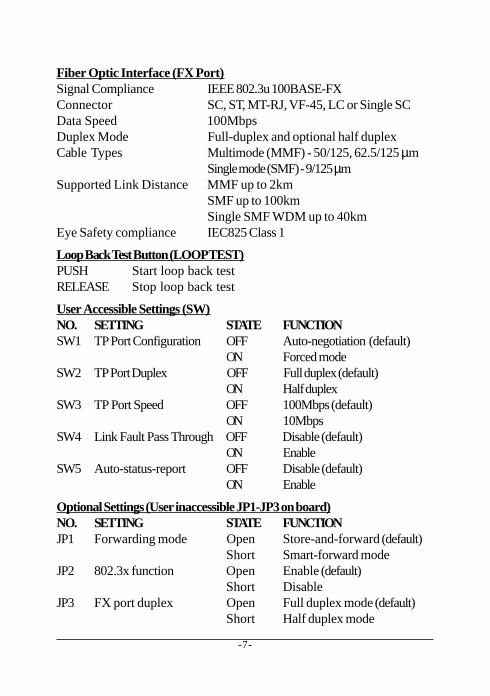
Fiber Optic Interface (FX Port)Signal Compliance IEEE 802.3u 100BASE-FXConnector SC, ST, MT-RJ, VF-45, LC or Single SCData Speed 100MbpsDuplex Mode Full-duplex and optional half duplexCable Types Multimode (MMF) - 50/125, 62.5/125 µm
Single mode (SMF) - 9/125 µmSupported Link Distance MMF up to 2km
SMF up to 100kmSingle SMF WDM up to 40km
Eye Safety compliance IEC825 Class 1
Loop Back Test Button (LOOP TEST)PUSH Start loop back testRELEASE Stop loop back test
User Accessible Settings (SW)NO. SETTING STATE FUNCTIONSW1 TP Port Configuration OFF Auto-negotiation (default)
ON Forced modeSW2 TP Port Duplex OFF Full duplex (default)
ON Half duplexSW3 TP Port Speed OFF 100Mbps (default)
ON 10MbpsSW4 Link Fault Pass Through OFF Disable (default)
ON EnableSW5 Auto-status-report OFF Disable (default)
ON Enable
Optional Settings (User inaccessible JP1-JP3 on board)NO. SETTING STATE FUNCTIONJP1 Forwarding mode Open Store-and-forward (default)
Short Smart-forward modeJP2 802.3x function Open Enable (default)
Short DisableJP3 FX port duplex Open Full duplex mode (default)
Short Half duplex mode

-8-
LED IndicatorsLED DISPLAY STATE INTERPRETATIONPWR Power status ON Power on
OFF Power offTP LINK TP port link status ON Link up and no traffic
OFF Link faultBlink Rx/Tx activities
TP 100M TP port speed status ON 100MbpsOFF 10Mbps
TP FDX TP port duplex status ON Full duplexOFF Half duplexBlink Collisions on half duplex
FX LINK FX port link status ON Link up and no trafficOFF Link faultBlink Rx/Tx activities
FX OL FX port optical link ON Optical signal is detectedOFF No optical signal
RTP LINK Remote TP port link ON Link up and no trafficOFF Link fault
RTP 100M Remote TP port speed ON 100MbpsOFF 10Mbps
RTP FDX Remote TP port duplex ON Full duplexOFF Half duplex
RTP LINK/100M/FDX LEDs are also used for loop back test report.
DC Power InputDC Input Jack D 6.3mm D 2.0mmOperating Input Voltages +4.75V ~ +12.6VPower consumption 2W max. (0.27A @+7.5V)Power Supply Options External AC-DC power adapters
Rated AC120V/60Hz DC7.5V 1ARated AC230V/50Hz DC7.5V 1ARated AC100V/50-60Hz DC7.5V 1ARated AC100V/50-60Hz DC5V 1ARated AC240V/50Hz DC7.5V 1A

-9-
Center ConnectorConnector Futurebus 6x4Function Center chassis installationSignals Power inputs
GroundManagement interfaces
Basic InformationForwarding Throughput Full wire speed at 100M full duplex
10Mbps - 14,880 pps at 64-byte packets100Mbps - 148,800pps at 64-byte packets
Packet Types Transparent and no modification for- IEEE 802.3 standard packets- IEEE 802.1Q VLAN tagged packets
Packet Length Up to 1522 bytes at store-and-forward modeNo limit at smart-forward mode 100to100
Flow Control Back-pressure for half-duplex mode802.3x pause-frame base for full duplex mode
MechanicalDimension H 23mm x W 72.5mm x D 108mmHousing Enclosed metal with no fanMounting Desktop, Wall mount, Center chassisWeight 212g
EnvironmentalOperating Temperature -20oC ~ 60oC (KC-300DM-EC)
-5oC ~ 40oC (Other models)Storage Temperature -20oC ~ 85oCRelative Humidity 5% ~ 90%
CertificateFCC Part 15 Class BCE/EMC EMI EN50081-1 Class B, EMS EN55024CE/LVD EN 60950

-10-
1.3 Optical SpecificationsThe media converter series provides the following fiber options:Duplex Fiber SeriesModel Port Fiber Wavelength Tx Power Rx Sensitivity300DM-T ST MMF 1310nm -19 ~ -14dBm -31dBm300DM-C SC MMF 1310nm -19 ~ -14dBm -31dBm300DM-EC SC MMF 1310nm -20 ~ -14dBm -31dBm300DM-JM MT-RJ MMF 1310nm -19 ~ -14dBm -31dBm300DM-VM VF-45 MMF 1310nm -20 ~ -14dBm -31dBm300DM-SA2 SC SMF 1310nm -15 ~ -8dBm -31dBm300DM-SL2 SC SMF 1310nm -15 ~ -8dBm -32dBm300DM-SL3 SC SMF 1310nm -15 ~ -8dBm -34dBm300DM-SL4 SC SMF 1310nm -5 ~ 0dBm -34dBm300DM-SL6 SC SMF 1310nm -5 ~ 0dBm -35dBm300DM-SL7 SC SMF 1310nm -3 ~ +3dBm -37dBm300DM-SL9 SC SMF 1310nm 0 ~ +5dBm -37dBm300DM-SL10 SC SMF 1550nm -3 ~ +3dBm -37dBm300DM-SL12 SC SMF 1550nm 0 ~ +5dBm -37dBm
Single Fiber Bi-Di WDM SeriesModel Port Fiber Wavelength Tx Power Rx Sensitivity300DM-W3515 SC SMF Tx 1310nm -14 ~ -8dBm -31dBm
Rx 1550nm300DM-W5315 SC SMF Tx 1550nm -14 ~ -8dBm -31dBm
Rx 1310nm300DM-W3540 SC SMF Tx 1310nm -8 ~ 0dBm -34dBm
Rx 1550nm300DM-W5340 SC SMF Tx 1550nm -8 ~ 0dBm -34dBm
Rx 1310nmSingle Mode CWDM SeriesModel Port Fiber Wavelength Tx Power Rx Sensitivity300DM-CxxW40 SC SMF Tx 1xx0nm -5 ~ 0dBm -35dBm
Rx 1100-1650nm300DM-CxxW80 SC SMF Tx 1xx0nm 0 ~ +5dBm -37dBm
Rx 1100-1650nm
-11-
1.4 Special Functions1.4.1 Auto MDI/MDI-X FunctionThis function allows the TP port to auto-detect the twisted-pair signalsand adapts itself to form a valid MDI to MDI-X connection with theremote connected device automatically.
1.4.2 Auto-negotiation FunctionWhen TP port is set on Auto-negotiation mode (SW1:ON), it is featuredwith auto-negotiation function and full capability. It performs a negotia-tion process for the speed and duplex configuration with the connecteddevice automatically when each time a link is being established.
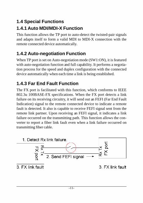
1.4.3 Far End Fault FunctionThe FX port is facilitated with this function, which conforms to IEEE802.3u 100BASE-FX specifications. When the FX port detects a linkfailure on its receiving circuitry, it will send out an FEFI (Far End FaultIndication) signal to the remote connected device to indicate a remotefault is detected. It also is capable to receive FEFI signal sent from theremote link partner. Upon receiving an FEFI signal, it indicates a linkfailure occurred on the transmitting path. This function allows the con-verter to report a fiber link fault even when a link failure occurred ontransmitting fiber cable.
-12-
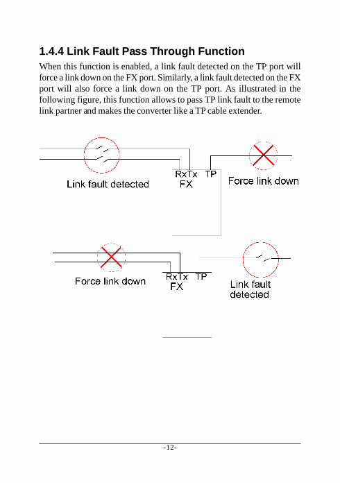
1.4.4 Link Fault Pass Through FunctionWhen this function is enabled, a link fault detected on the TP port willforce a link down on the FX port. Similarly, a link fault detected on the FXport will also force a link down on the TP port. As illustrated in thefollowing figure, this function allows to pass TP link fault to the remotelink partner and makes the converter like a TP cable extender.
-13-
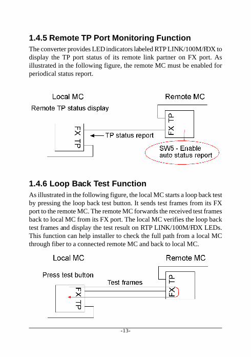
1.4.5 Remote TP Port Monitoring FunctionThe converter provides LED indicators labeled RTP LINK/100M/FDX todisplay the TP port status of its remote link partner on FX port. Asillustrated in the following figure, the remote MC must be enabled forperiodical status report.
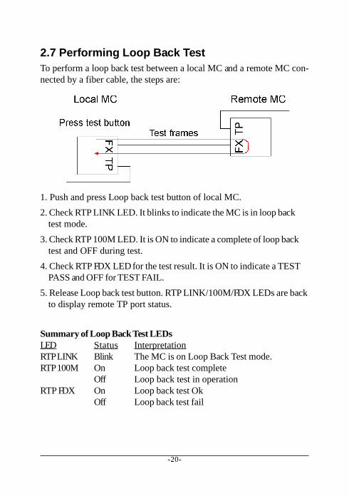
1.4.6 Loop Back Test FunctionAs illustrated in the following figure, the local MC starts a loop back testby pressing the loop back test button. It sends test frames from its FXport to the remote MC. The remote MC forwards the received test framesback to local MC from its FX port. The local MC verifies the loop backtest frames and display the test result on RTP LINK/100M/FDX LEDs.This function can help installer to check the full path from a local MCthrough fiber to a connected remote MC and back to local MC.
-14-
2. Installation2.1 UnpackingCheck that the following components have been included:• Installation guide (or contained in the product CD)• 10/100 Media Converter• One AC power adapter
If any item is found missing or damaged, please contact your local resellerfor replacement.
2.2 Mounting the DeviceDesktop MountingThe media converter can be mounted on a desktop or shelf. Make surethat there is proper heat dissipation from and adequate ventilation aroundthe device. Do not place heavy objects on the device.
Wall MountingThe media converter also can be mounted on a wall. On bottom of thedevice, wall mounting hole is provided for wall mounting.
Installation into Center Chassis KC-1300The media converter also can be installed in KC-1300 center chassis. Thecenter chassis provides the power supply to the converter. Up to 16 unitscan be installed in one chassis. Unscrew and remove the cover of thecenter connector before inserting the converter into the chassis. Refer tothe operation manual of center chassis KC-1300 for more information.

-15-
2.3 Applying PowerBefore you begin the installation, check the AC voltage of your area. TheAC power adapter which is used to supply the DC power for the unit shouldhave the AC voltage matching the commercial power voltage in your area.
The AC Power Adapter Specifications
AC input power: AC power voltage of your area, options -Rated AC120V/60Hz DC7.5V 1ARated AC230V/50Hz DC7.5V 1ARated AC100V/50-60Hz DC7.5V 1ARated AC100V/50-60Hz DC5V 1ARated AC240V/50Hz DC7.5V 1A
Steps to apply the power to the converters are:
1. Connect power adapter DC plug to the DC input jack located on theback of the converter before connecting to the AC outlet.
2. To ensure against accidental disconnection, tie the DC cable withthe cable tie located the back of the converter.
3. Connect the power adapter to the AC outlet.4. Check Power LED indication.
-16-
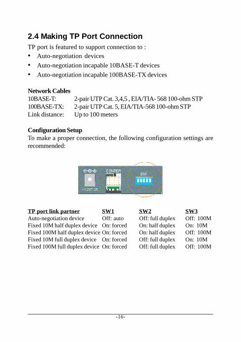
2.4 Making TP Port ConnectionTP port is featured to support connection to :• Auto-negotiation devices• Auto-negotiation incapable 10BASE-T devices• Auto-negotiation incapable 100BASE-TX devices
Network Cables10BASE-T: 2-pair UTP Cat. 3,4,5 , EIA/TIA- 568 100-ohm STP100BASE-TX: 2-pair UTP Cat. 5, EIA/TIA-568 100-ohm STPLink distance: Up to 100 meters
Configuration SetupTo make a proper connection, the following configuration settings arerecommended:
TP port link partner SW1 SW2 SW3Auto-negotiation device Off: auto Off: full duplex Off: 100MFixed 10M half duplex device On: forced On: half duplex On: 10MFixed 100M half duplex device On: forced On: half duplex Off: 100MFixed 10M full duplex device On: forced Off: full duplex On: 10MFixed 100M full duplex device On: forced Off: full duplex Off: 100M
-17-
2.5 Making FX Port ConnectionFX port operates on 100Mbps and full duplex (factory default). A varietyof fiber options is provided as follows:
Duplex Fiber Series
Model Connector Wavelength Fiber Ref. distance300DM-T ST 1310nm Duplex MMF 2km300DM-C SC 1310nm Duplex MMF 2km300DM-JM MT-RJ 1310nm Duplex MMF 2km300DM-VM VF-45 1310nm Duplex MMF 2km300DM-SA2 SC 1310nm Duplex SMF 20km300DM-SL2 SC 1310nm Duplex SMF 20km300DM-SL3 SC 1310nm Duplex SMF 30km300DM-SL4 SC 1310nm Duplex SMF 40km300DM-SL6 SC 1310nm Duplex SMF 60km300DM-SL7 SC 1310nm Duplex SMF 70km300DM-SL9 SC 1310nm Duplex SMF 90km300DM-SL10 SC 1550nm Duplex SMF 100km300DM-SL12 SC 1550nm Duplex SMF 120km
Duplex Fiber CWDM Series
Model Connector Wavelength Fiber Ref. Distance300DM-CxxW40 SC Tx 1xx0nm SMF 40km
Rx 1100 - 1650nm
300DM-CxxW80 SC TX 1xx0nm SMF 80kmRX 1100 - 1650nm
Tx 1xx0nm : 1470, 1490, 1510, 1530, 1550, 1570, 1590, 1610nm
-18-
Single Fiber Bi-Di WDM Series
Model Connector Wavelength Fiber Ref. Distance300DM-W3515 Bi-Di SC Tx 1310nm Single SMF 15 - 20km
Rx 1550nm300DM-W5315 Bi-Di SC Tx 1550nm Single SMF 15 - 20km
Rx 1310nm300DM-W3540 Bi-Di SC Tx 1310nm Single SMF 40km
Rx 1550nm300DM-W5340 Bi-Di SC Tx 1550nm Single SMF 40km
Rx 1310nm
Since the WDM single fiber media converters use different wavelengthsfor transmission and receiving respectively, the link partner device lo-cated on the remote end of the single fiber should match the wavelengthused on the single fiber converter.

-19-
2.6 LED IndicatorsLink Fault Pass Through Function is disabledLED Display Status InterpretationPWR Power status On Power on
Off Power offTP LINK TP port link status On Link up and no traffic
Off Link faultBlink Rx/Tx activities
TP 100M TP port speed status On 100MbpsOff 10Mbps
TP FDX TP port duplex status On Full duplexOff Half duplexBlink Collisions on half duplex
FX LINK FX port link status On Link up and no trafficOff Link faultBlink Rx/Tx activities
FX OL FX port optical link On Optical signal is detectedOff No optical signal is detected
Link Fault Pass Through Function is enabledTP LINK FX LINK FX OL Interpretation
On On On Both TP and FX ports link upOff Off On (1) TP port link fault or
(2) FX port received FEFI signal(FX port Tx path failed.)
Off Off Off (1) TP port link fault or(2) FX port Rx link failure detected
Remote TP port monitoringLED Display Status InterpretationRTP LINK Remote TP port link On Link up and no traffic
Off Link faultRTP 100M Remote TP port speed On 100Mbps
Off 10MbpsRTP FDX Remote TP port duplex On Full duplex
Off Half duplex
-20-
2.7 Performing Loop Back TestTo perform a loop back test between a local MC and a remote MC con-nected by a fiber cable, the steps are:
1. Push and press Loop back test button of local MC.2. Check RTP LINK LED. It blinks to indicate the MC is in loop back
test mode.3. Check RTP 100M LED. It is ON to indicate a complete of loop back
test and OFF during test.4. Check RTP FDX LED for the test result. It is ON to indicate a TEST
PASS and OFF for TEST FAIL.5. Release Loop back test button. RTP LINK/100M/FDX LEDs are back
to display remote TP port status.
Summary of Loop Back Test LEDsLED Status InterpretationRTP LINK Blink The MC is on Loop Back Test mode.RTP 100M On Loop back test complete
Off Loop back test in operationRTP FDX On Loop back test Ok
Off Loop back test fail
-21-
3. Optional Configuration SettingsThe media converter provides additional configuration settings whichare user-inaccessible. The settings are built on the board inside the prod-uct case. The settings are provided for technical installers to adapt theconverter to fit some specific application needs.
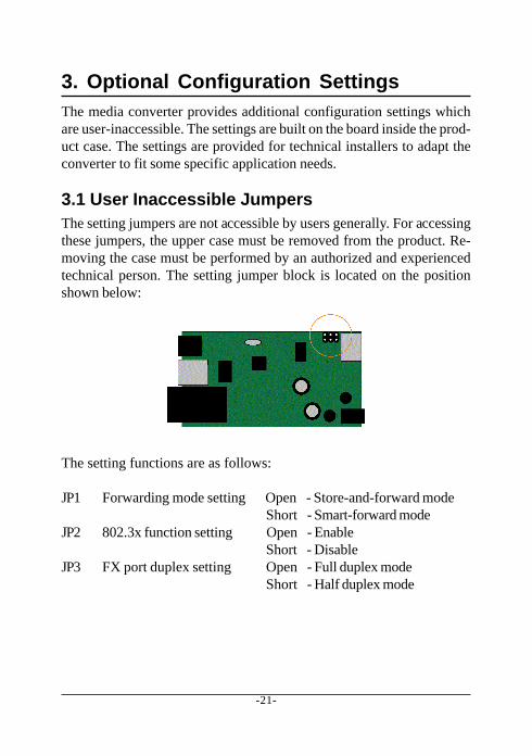
3.1 User Inaccessible JumpersThe setting jumpers are not accessible by users generally. For accessingthese jumpers, the upper case must be removed from the product. Re-moving the case must be performed by an authorized and experiencedtechnical person. The setting jumper block is located on the positionshown below:
The setting functions are as follows:
JP1 Forwarding mode setting Open - Store-and-forward modeShort - Smart-forward mode
JP2 802.3x function setting Open - EnableShort - Disable
JP3 FX port duplex setting Open - Full duplex modeShort - Half duplex mode
-22-
3.1.1 Forwarding Mode Setting JP1The following table lists the forward method used in different TP to FXconversions:
JP1 Setting TP port to/from FX port Forward methodStore-and-forward 10BASE-T to 100BASE-FX Store and forward
100BASE-TX to 100BASE-FX Store and forwardSmart-forward 10BASE-T to 100BASE-FX Store and forward
100BASE-TX to 100BASE-FX Direct conversion
On smart-forward mode, the converter can change to direct conversionautomatically when it detects same speed on both TP port and FX port.Direct conversion method converts the signal between TP port and FXport without storing the received packet on one port then forwarding toanother port. The media converter operates with the minimum latency.
Note:1. In direct conversion, be sure both devices connected to the TP port
and FX port have same duplex mode for proper transmission.2. In direct conversion, 802.3x function is disabled and the media
converter will not generate pause frame, but just forwards thereceived pause frame directly from one port to another port.
3. In direct conversion, the media converter is not limited to themaximal length of the receiving packets.
-23-
3.1.2 802.3x Function Setting JP2IEEE 802.3x function is the flow control method used for full duplex op-eration on TP port and FX port under store and forward mode. Thismethod uses pause frames for one port to stop further transmission fromits link partner.
3.1.3 FX Duplex Setting JP3This setting is used to set the duplex mode of the FX port.
3.2 JP1-JP3 Factory Default SettingsThe factory default settings for JP1, JP2, and JP3 are as follows:
JP1 Open Store-and-forward modeJP2 Open 802.3x function is enabledJP3 Open FX port full duplex


![KGC-310M-B Installation Guide [R] 120528 - KTI Net · KTI Networks Inc. reserves the right to revise this documentation and to make changes in content from time to time without obligation](https://static.documents.pub/doc/80x56/5cc7890f88c993fb628c21ea/kgc-310m-b-installation-guide-r-120528-kti-kti-networks-inc-reserves-the.jpg)


