14. Hi~h-Volta~e AC/DC Conversion or Rectification Vacuum tubes, or electron devices, are unidirectional conductors. Electron charge carriers will only go in one direction. Therefore, at some point in the realization of a microwave-tube transmitter a source of direct current (de) will have to be provided, and often at very high voltages consisting of tens or even hundreds of kilovolts. The storage of electrical energy in large capacitor banks is also a unidirectional process, even though dc cannot flow through a capacitor. (Charge is stored in a capacitor by the flow of current into it in one direction and removed by a current out of it in the opposite direction. But these directions, once established, do not change.) Almost no microwave-tube transmitters of significant power output are directly powered from a primary source of dc, such as a battery, thermoelectric device, or dc generator. (Some very exotic, single- shot, explosive-energy electrical converters do find uses, though.) Many sys- tems, however, are indirectly powered from such sources, but only after voltage- level conversion that involves the internal generation of alternating current by means of an inverter. Other transmitters are indirectly powered from external sources of alternating current (at), such as commercial power grids or dedicated alternators. In all of these cases conversion from ac to dc, which is called rectifi- cation, is required before it can be used to power our microwave-tube transmitter electron beam (or beams). 14.1 Polyphase ac concepts Every engineer knows something about ac-dc rectification, but a few still don’t know much about polyphase rectification-or even polyphase ac circuits, for that matter. As power levels increase, polyphase circuits become more and more efficacious, and at the higher power levels already discussed they are all but mandatory. Commercial power is generated and distributed in the form of three balanced phases comprising voltage vectors that are displaced from one another by 120°, as shown in Fig. 14-1. A number of advantages accrue from this arrangement. ● ● ● ● The current in the conductor connecting the neutral, or common point, of a wye-connected source and the common point of a balanced, wye-con- nected load has a vector sum that is zero. The vector sum of voltages around a properly phased, delta-connected source is also zero, allowing the delta to be “closed” without circulating current. The vector sum of the mechanical forces on the windings of a three-phase alternator is also zero, so that there are no unbalanced rotational forces. The mechanical forces on the rotor of a three-phase motor are Durelv . rotational, which is most desirable. x . Aswe will see, there are additional advantages to three-phase operation when it 263
Transcript
14. Hi~h-Volta~e AC/DC Conversionor Rectification
Vacuum tubes, or electron devices, are unidirectional conductors. Electroncharge carriers will only go in one direction. Therefore, at some point in therealization of a microwave-tube transmitter a source of direct current (de) willhave to be provided, and often at very high voltages consisting of tens or evenhundreds of kilovolts. The storage of electrical energy in large capacitor banks isalso a unidirectional process, even though dc cannot flow through a capacitor.(Charge is stored in a capacitor by the flow of current into it in one direction andremoved by a current out of it in the opposite direction. But these directions,once established, do not change.) Almost no microwave-tube transmitters ofsignificant power output are directly powered from a primary source of dc, suchas a battery, thermoelectric device, or dc generator. (Some very exotic, single-shot, explosive-energy electrical converters do find uses, though.) Many sys-tems, however, are indirectly powered from such sources, but only after voltage-level conversion that involves the internal generation of alternating current bymeans of an inverter. Other transmitters are indirectly powered from externalsources of alternating current (at), such as commercial power grids or dedicatedalternators. In all of these cases conversion from ac to dc, which is called rectifi-cation, is required before it can be used to power our microwave-tube transmitterelectron beam (or beams).
14.1 Polyphase ac conceptsEvery engineer knows something about ac-dc rectification, but a few still
don’t know much about polyphase rectification-or even polyphase ac circuits,for that matter. As power levels increase, polyphase circuits become more andmore efficacious, and at the higher power levels already discussed they are allbut mandatory.
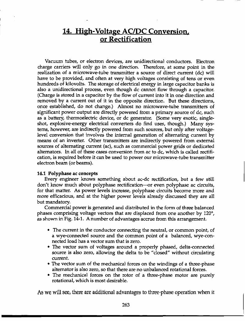
Commercial power is generated and distributed in the form of three balancedphases comprising voltage vectors that are displaced from one another by 120°,as shown in Fig. 14-1. A number of advantages accrue from this arrangement.
●
●
●
●
The current in the conductor connecting the neutral, or common point, ofa wye-connected source and the common point of a balanced, wye-con-nected load has a vector sum that is zero.The vector sum of voltages around a properly phased, delta-connectedsource is also zero, allowing the delta to be “closed” without circulatingcurrent.The vector sum of the mechanical forces on the windings of a three-phasealternator is also zero, so that there are no unbalanced rotational forces.The mechanical forces on the rotor of a three-phase motor are Durelv.rotational, which is most desirable.
x .
Aswe will see, there are additional advantages to three-phase operation when it
263
264 High-Power Microwave-Tube Transmitters
L “I (in-phase)
Q (quadrature phase)
-0.866(2 120”
6I~ -0.51
I
c B
to.866Qll
YE I
A (+1)
B (+0.8660 - jO.51)
c (4.866 - p.51)
Figure 14-1. If you start with two phases, you can make the rest.
comes to rectification.A balanced, rotating electrical machine is not the only source of a three-phase
electrical system, however; nor is there anything magical about just three phases.To create a system having a theoretically unlimited number of discxete phases, allwe need to start with is two. And it theoretically does not matter how infinitesi-mal the phase difference is between them. Even if the difference is a microradian,one vector can be resolved into components that are in-phase and quadrature-phase (I and Q) with respect to the other. Indeed, modern digital signal process-ing is based on transforming a repetitive waveform into its Fourier series ofharmonically related components and evaluating two samples of each, the I andQ components.
Given two voltage vectors of the same amplitude that are in quadrature (whichis sometimes called a hi-phase system) and two transformers with identical pri-mary windings and secondary winding ratios and polarities as shown in Fig. 14-
High-Voltage AC/DC Conversion or Rectification (14) 265
1, a balanced three-phase system can be synthesized. Different transformer wind-ing ratios will accomplish the same thing for different ratios of quadrature-phasedvector amplitudes. It also should be obvious that there is no reason to be limitedto just three phases. More transformers will produce more phases.
14.2 The three-phase, half-wave rectifierSingle-phase ac rectifiers require external hold-up for either load current (the
inductor-input filter) or load voltage (the capacitor-input filter) if the load re-quires non-varying direct current. Without some form of energy storage betweenthe rectifier and a resistive load, the closest that load voltage and current can evercome to non-varying dc is a succession of half-sine-wave segments, all of thesame polarity, all with infinite peak-to-valley ratio. It is direct current, to be sure,but a long way from non-varying. Polyphase ac rectification overcomes thisproblem.
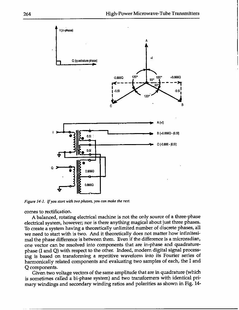
The simplest form of three-phase rectifier is the half-wave, or three-pulserectifier, as shown in Fig. 14-2. The transformer secondary is wye-connected. Arectifier diode is placed in series with each phase, and the return from the load isto the neutral point. The rectifier shown is connected for positive-polarity dcoutput. Whichever phase-A, B, or C—is instantaneously more positive than theother two will be the conducting phase, and conduction will continue for 120°, or1/3 cycle, with the peak voltage at the center of the conducting interval. The“natural” commutation point, or transfer point between the phases, occurs when
I
LI
~ V2
4
VM
I
. _ Phaae A - Phase B
1-/- voifaga
Ons cycle, phase A ~’. ------ -+
..”
Bafore ! “. 1 ~ - ~mm~a~n ~mnt.induclanca
-1..’” ‘> ~ (Phase A- Phase B)W2X
IId —,
r-
Figure 14-2. The effect of ac line reactance on rectifier current commutation.
266 High-Power Microwave-Tube Transmitters
the instantaneous voltage of the next sequential phase becomes more positivethan the previously conducting phase. At this point for either zero per-phasesource inductance or zero load current, the load voltage will simply follow thatof the newly conducting phase. This pattern ~peats itself throughout succes-sive phase rotations. The load voltage, therefore, will be a series of sinusoid topsspanning each wave’s -60° point to its +60° point. There will be three such topsper cycle, hence the term “three-pulse,” or “three-bump,” rectifier. If the peakvoltage is uni~, the instantaneous voltage at the commutation point is 0.5, so thepeak-to-valley ratio is 2. The theoretical no-load (or no-source-inductance) Fou-rier series for the frequency spectrum of the load voltage is
3—xsin~
[1+:cos3cM-:cos6a)t +
3:COS 90K +
(3n~ -1 1cos 3ntw .
z
The first term has a value of 0.907, which is the ratio of the zero-frequency oraverage, “de” component of output voltage to the peak value of input voltage,even though the valleys of the waveform are only 1/2 as great as the peaks.(Note that the comparable first term for single-phase, full-wave [or two-pulse]rectification is 2/n x sin(7c/2), which is 0.636. This is the case, even though itsorder of rectification, or pulse number, is 2/3 that of the simplest three-phaserectifier.) The other terms in the series am the ripple components, the first ofwhich, theoretically, is the third harmonic.
If, however, the three-phase source inductance is not zero-and it never is—and load current is not zero either, the output voltage will not simply follow thetops of the phase voltages. The three-phase source impedance will consist prima-rily of transformer winding resistance, R, and the reactance of the leakage induc-tance, X. The resistance is usually no more than 1/5 as great as the reactance andcan be ignored as a contributor to total ac impedance. Assuming that inductor Lin series with the load is sufficiently large, the output current will be non-varyingdc. However, the inductance in series with each phase-inductance throughwhich load current is also flowing-will resist the transfer, or commutation, ofthe load current to the incoming phase. It will develop whatever voltage acrossitself that is required to keep its diode forward biased and current going throughit. Fortunately, there is a countervailing current called commutation current thatopposes the inductor current, eventually forcing it to zero and permitting thecommutation of load current to the next phase in line. The commutation currentis driven by the vector sum of the outgoing and incoming phase voltages (shownas A and B in the Fig. 14-2) and limited by the reactance of the two phases inseries. Heading positive, the driving voltage for commutation current passesthrough zero at the natural commutation point. Being limited by inductive reac-tance, however, the commutation current lags the voltage by 90°, hence it ispassing through a negative peak at that time. During the time that the commu-tating current is driving the load current from one phase to the next, which isknown as the commutation angle, the output voltage follows neither phase volt-age but rather the average of the two. Therefore, the output average voltage isless positive than the incoming phase voltage but more positive than the outgo-
High-Voltage AC/DC Conversion or Rectification (14) 267
ing phase voltage. At the end of the comm~tation event, current has transferredto the new phase, and the output voltage abruptly jumps up to coincide with thenew phase voltage at that instant. The voltage follows it along until the nextcommutation point is reached, where the process is again repeated. The relativedifficulty of the commutation and the length of the commutation angle are pro-portional to what is called the commutation factor, which is the product of loadcurrent and phase reactance divided by phase voltage.
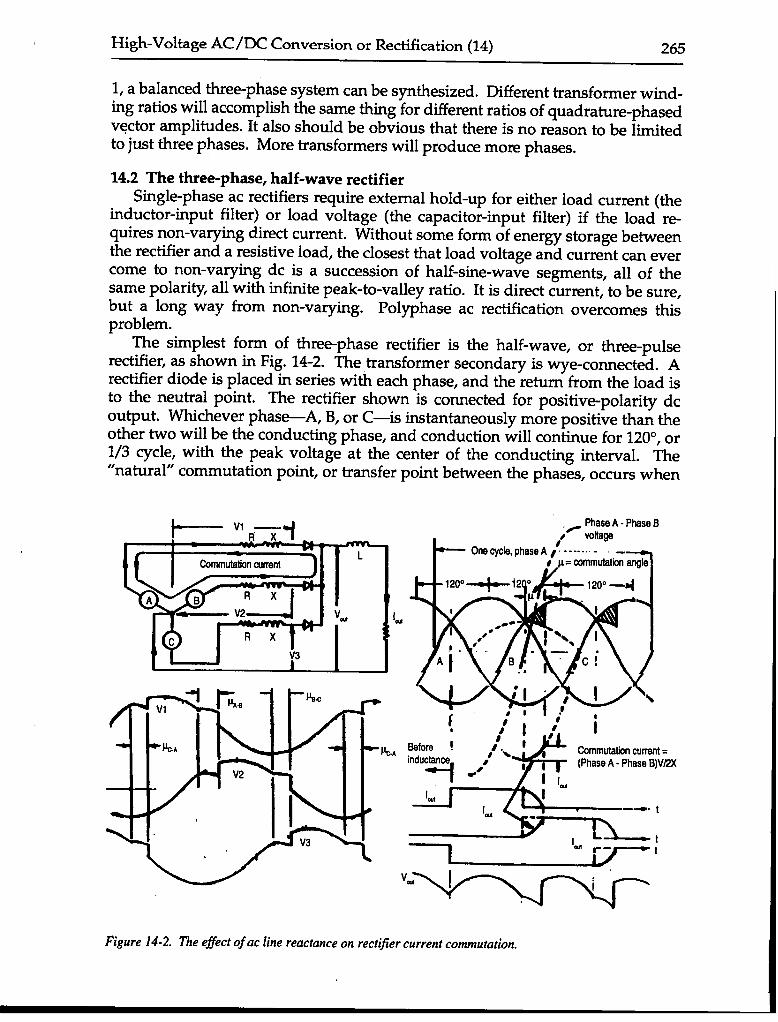
14.3 The three-phase, full-wave (six-pulse) rectifierThe three-phase, half-wave (or three-pulse) rectifier described above is used
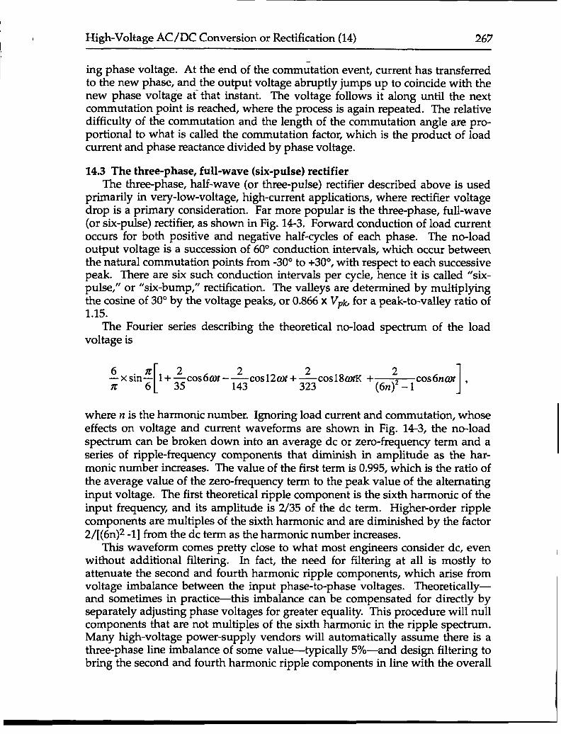
primarily in very-low-voltage, high-current applications, where rectifier voltagedrop is a primary consideration. Far more popular is the three-phase, full-wave(or six-pulse) rectifier, as shown in Fig. 143. Forward conduction of load currentoccurs for both positive and negative half-cycles of each phase. The no-loadoutput voltage is a succession of 60° conduction intervals, which occur betweenthe natural commutation points from -30° to +30°, with respect to each successivepeak. There are six such conduction intervals per cycle, hence it is called “six-pulse,” or “six-bump,” rectification. The valleys are determined by multiplyingthe cosine of 30° by the voltage peaks, or 0.866 x VP~ for a peak-to-valley ratio of1.15.
The Fourier series describing the theoretical no-load spectrum of the loadvoltage is
6—xsinZ
[1+ &cos6ax
2 2
6–—cos12ax+—
z 143 323 1c0s18@m ‘(6n; -1 c0s6n@t ‘
where n is the harmonic number. Ignoring load current and commutation, whoseeffects on voltage and current waveforms are shown in Fig. 143, the no-loadspectrum can be broken down into an average dc or zero-frequency term and aseries of ripple-frequency components that diminish in amplitude as the har-monic number increases. The value of the first term is 0.995, which is the ratio ofthe average value of the zero-frequency term to the peak value of the alternatinginput voltage. The first theoretical ripple component is the sixth harmonic of theinput frequency, and its amplitude is 2/35 of the dc term. Higher-order ripplecomponents are multiples of the sixth harmonic and are diminished by the factor2/[(6n)z -1] from the dc term as the harmonic number increases.
This waveform comes pretty close to what most engineers consider dc, evenwithout additional filter~g. h fact, the need for fil~ering at all is mostly toattenuate the second and fourth harmonic ripple components, which arise fromvoltage imbalance between the input phase-to-phase voltages. Theoretically—and sometimes in practic%this imbalance can be compensated for directly byseparately adjusting phase voltages for greater equality. This procedure will nullcomponents that are not multiples of the sixth harmonic in the ripple spectrum.Many high-voltage power-supply vendors will automatically assume there is athree-phase line imbalance of some value-typically 5%-and design filtering tobring the second and fourth harmonic ripple components in line with the overall
268 High-Power Microwave-Tube Transmitters
1, x R
r \
-.—.
—. —.—-
1
t
Vti
0
1,
4
1,
Figure 14-3. The three-phase, jidl-wave, or six-pulse rectifier
ripple requirement.
14.4 The six-phase, full-wave (12-pulse) rectifierAs popular as the six-pulse rectifier has become for high-power, high-voltage
applications, the 12-pulse rectifier is rapidly supplanting it as the configurationof choice. Even though it requires two full-wave bridge rectifiers instead of oneand two separate secondary windings to feed them, the total number of rectifierjunctions is usually the same. This is because series-connected individual recti-fier junctions are required to provide the total reverse-voltage capability and itdoes not matter whether they are connected as one bridge or two. The trans-former core and coil combination is also much the same, except the secondary isdivided two halves from a total volt-ampere perspective.
High-Voltage AC/DC Conversion or Rectification (14) 269
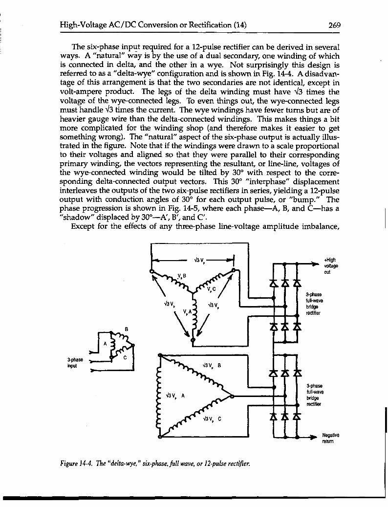
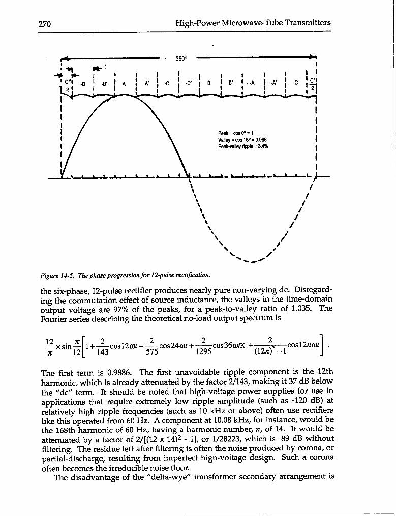
The six-phase input required for a 12-pulse rectifier can be derived in severalways. A “natural” way is by the use of a dual secondary, one winding of whichis connected in delta, and the other in a wye. Not surprisingly this design isreferred to as a “delta-wye” configuration and is shown in Fig. 14-4. A disadvan-tage of this arrangement is that the two secondaries are not identical, except involt-ampere product. The legs of the delta winding must have 43 times thevoltage of the wye-connected legs. To even things out, the wye-connected legsmust handle 43 times the current. The wye windings have fewer turns but are ofheavier gauge wire than the delta-connected windings. This makes things a bitmore complicated for the winding shop (and therefore makes it easier to getsomething wrong). The “natural” aspect of the six-phase output is actually illus-trated in the figure. Note that if the windings were drawn to a scale proportionalto their voltages and aligned so that they were parallel to their correspondingprimary winding, the vectors representing the resultant, or line-line, voltages ofthe w-ye-connected winding would be tilted by 30° with respect to the corre-sponding delta-connected output vectors. This 30° “interphase” displacementinterleaves the outputs of the two six-pulse rectifiers in series, yielding a 12-pulseoutput with conduction angles of 30° for each output pulse, or “bump.” Thephase progression is shown in Fig. 14-5, where each phas~A, B, and C—has a“shadow” displaced by 30”—A’, B’, and C’.
Except for the effects of any three-phase line-voltage amplitude imbalance,
I 1
B
B
A
3-phaae cinput
- “v,--+ +Highvoltageout
43v,
Figure14-4. ‘I’he“delta-wye,” six-phase, fill wave, or 12-pulse rectifier.
270 High-Power Microwave-Tube Transmitters
~“ 360° *i
n-~-+ ~:~
tI I1I
1
: Peak= wsoO=l I
Valley = cos 15” =0.966 1I Peak-vallay rippla = 3.4% II
1I I
~. ~.~L
\, /\ /tt It\\ /’\ /\\\ ,/\\\ /\ -~
Figure 14-5. The phase progression for 12-pulse rectification.
the six-phase, 12-pulse rectifier produces nearly pum non-varying dc. Disxvgard-ing the commutation effect of source inductance, the valleys in the time-domainoutput voltage are 97% of the peaks, for a peak-to-valley ratio of 1.035. TheFourier series describing the theoretical no-load output spectrum is
[
122~in 7C 2 2 2~ 1+ —cos12at –—cos24@t +—
z 143 575 1295 1c0s36@K ‘(12n;’ -lc0s12n@f “
The first term is 0.9886. The first unavoidable ripple component is the 12thharmonic, which is already attenuated by the factor 2/143, making it 37 dB belowthe “de” term. It should be noted that high-voltage power supplies for use inapplications that require extremely low ripple amplitude (such as -120 dB) atrelatively high ripple frequencies (such as 10 kHz or above) often use rectifierslike this operated from 60 Hz. A component at 10.08 kHz, for instance, would bethe 168th harmonic of 60 Hz, having a harmonic number, n, of 14. It would beattenuated by a factor of 2/[(12 x 14)2 - 1], or 1/28223, which is -89 dB withoutfiltering. The residue left after filtering is often the noise produced by corona, orpartial-discharge, resulting from imperfect high-voltage design. Such a coronaoften becomes the irreducible noise floor.
The disadvantage of the “delta-wye” transformer secondary arrangement is
High-Voltage AC/DC Conversion or Rectification (14) 271
aA B
3-phaaainpul c1
PrimarywindiW
/
/
full-wave
Samndaty 1
3-phaaafull-wavebddgar~”fiar
+HQhvollagaout
Bamndary 2
Figure 14-6. 71e “emnded-delta” six-phase, jidl-wave, or 12-pulse recttjier.
largely overcome by the “extended-delta” pair of secondary windings, as shownin Fig. 14-6. In this case, identical secondary windings can be used. The wind-ings for each phase have taps, or “extensions,” at both ends. If the taps areproperly placed, making the connections shown will produce a +150 “tilt” to theline-line resultant voltage vectors of the upper secondary and a -15° tilt to thoseof the lower one, thus generating the 30° interphase angle between the outputs ofthe series-connected full-wave rectifiers.
14.5 The 12-phase, full-wave, 24-pulse rectifierFigure 14-7 shows an extension of the 12-pulse rectifier into a 24-pulse recti-
fier. This is an actual commercial design, comprising a pair of complete “delta-wye’’-type 12-pulse rectifiers, each with its own complete transformer. The pri-mary windings of the two transformers are identically wound and connected in aconfiguration called “almost delta,” or “polygon.” For both primary windings, asmall C-phase winding segment is connected between the A and B junction, asmall A-phase winding segment is connected between B and C, and a small B-phase winding segment is connected between C and A. Therefore, all phases areidentical. However, the feed lines from the incoming three-phase source are not
272 High-Power Microwave-Tube Transmitters
,
QA B
7.50 lag●“
c
4A B●* 7.5”
lad
c
&= 1 1 1 1
Figure 14-7. A 24-pulse rectljier system that uses polygon primaries.
4
Meter tap
-0
+
connected to identical points. The difference imparts a 7.5° lead to one resultantvoltage vector and 7.5° lag to the other for a total difference of 15° “inter-inter-phase.” In other words, that the two 12-pulse rectifier outputs are interleaved togive 15° conduction angle for each sequential phase segment.
As can well be imagined, there is no theoretical upper limit to how far suchpolyphase upscaling can be carried, but there is certainly a point of diminishingreturns. Although more than a few 24-pulse-rectifier systems are currently oper-ating, this configuration is considered the practical upper limit.
14.6 Polyphase-rectifier line currentSo far, the discussion of polyphase rectification has dwelt upon design and
user-friendly aspects, such as how close can the outputs come to true non-vary-ing dc, and how tenuous is the ripple spectrum. There is another reason toadmire polyphase rectification that is more selfless and environmentally friendly:it inherently ameliorates line-current harmonic pollution.
High-Voltage AC/DC Conversion or Rectification (14) 273
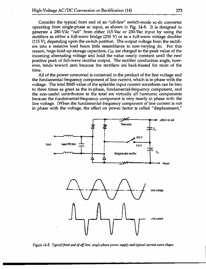
Consider the typical front end of an ~’off-line” switch-mode ac-dc converteroperating from single-phase ac input, as shown in Fig. 14-8. It is designed togenerate a 280-Vdc “rail” from either 115-Vac or 230-Vac input by using therectifiers as either a full-wave bridge (230 V) or as a full-wave voltage doubler(115 V), depending upon the switch position. The output voltage from the rectifi-ers into a resistive load bears little resemblance to non-varying dc. For thisreason, huge hold-up storage capacitors, CH, are charged to the peak value of theincoming alternating voltage and hold the value nearly constant until the nextpositive peak of full-wave rectifier output. The rectifier conduction angle, how-ever, tends toward zero because the rectifiers are back-biased for most of thetime.
All of the power consumed is contained in the product of the line voltage andthe fundamental-frequency component of line current, which is in phase with thevoltage. The total RMS value of the spikelike input current waveform can be twoto three times as great as the in-phase, fundamental-frequency component, andthe non-useful contributors to the total are virtually all harmonic componentsbecause the fundamental-frequency component is very nearly in phase with theline voltage. (When the fundamental-fmquency component of line current is notin phase with the voltage, the effect on power factor is called “displacement,”
~+’’’-vdc”i’Input Input RFI filter
Return
$Line voltage
Line currant
Figure14-8. ‘1’ypicalfrontendofofl-line, single-phase power supply and typical current wave shape.
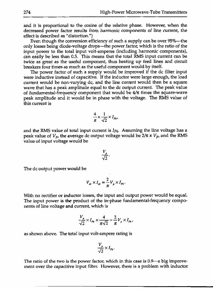
274 High-Power Microwave-Tube Transmitters
and it is proportional to the cosine of the relative phase. However, when thedecreased power factor Esults from harmonic components of line current, theeffect is described as “distortion.”)
Even though the conversion efficiency of such a supply can be over 95%-theonly losses being diode-voltage drops —the power factor, which is the ratio of theinput power to the total input volt-amperes (including harmonic components),can easily be less than 0.5. This means that the total RMS input current can betwice as great as the useful component, thus heating up feed lines and circuitbreakers four times as much as the useful component would by itself.
The power factor of such a supply would be improved if the dc filter inputwem inductive instead of capacitive. If the inductor were large enough, the loadcurrent would be non-varying dc, and the line current would then be a squarewave that has a peak amplitude equal to the dc output current. The peak valueof fundamental-frequency component that would be 4/n times the square-wavepeak amplitude and it would be in phase with the voltage. The RMS value ofthis current is
and the RMS value of total input current is Ipk. Assuming the line voltage has apeak value of VP, the average dc output voltage would be 2/n x VP, and the RMSvalue of input voltage would be
The dc output power would be
With no rectifier or inductor losses, the input and output power would be equal.The input power is the product of the in-phase fundamental-frequency compo-nents of line voltage and current, which is
as shown above. The total input volt-ampere rating is
~xIPk.
The ratio of the two is the power factor, which in this case is 0.9—a big improve-ment over the capacitive input filter. However, the~ is a problem with inductor
High-Voltage AC/DC Conversion or Rectification (14) 27.5
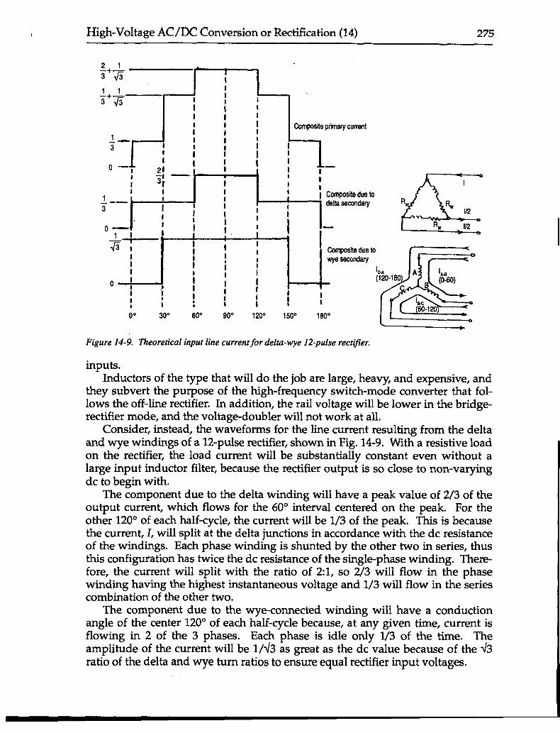
Figure 14-9. Theoretical input line current for delta-wye 12-pulse rectifier,
inputs.Inductors of the type that will do the job are large, hea~, and expensive, and
they subvert the purpose of the high-frequency switch-mode converter that fol-lows the off-line rectifier. In addition, the rail voltage will be lower in the bridge-rectifier mode, and the voltage-doubler will not work at all.
Consider, instead, the waveforms for the line current resulting from the deltaand wye windings of a 12-pulse rectifier, shown in Fig. 149. With a resistive loadon the rectifier, the load current will be substantially constant even without alarge input inductor filter, because the rectifier output is so close to non-varyingdc to begin with.
The component due to the delta winding will have a peak value of 2/3 of theoutput current, which flows for the 60° interval centered on the peak. For theother 120° of each half-cycle, the current will be 1/3 of the peak. This is becausethe current, I, will split at the delta junctions in accordance with the dc resistanceof the windings. Each phase winding is shunted by the other two in series, thusthis configuration has twice the dc resistance of the single-phase winding. Ther-efore, the current will split with the ratio of 2:1, so 2/3 will flow in the phasewinding having the highest instantaneous voltage and 1/3 will flow in the seriescombination of the other two.
The component due to the wye-connected winding will have a conductionangle of the center 120° of each half-cycle because, at any given time, current isflowing in 2 of the 3 phases. Each phase is idle only 1/3 of the time. Theamplitude of the current will be 1/43 as great as the dc value because of the d3ratio of the delta and wye turn ratios to ensure equal rectifier input voltages.
276 High-Power Microwave-Tube Transmitters
+1.0 Fundamental
o0° 30” 60° 90” Iw Iw 1P
Third harmonk
+1.0
.
0
-1.0
.
+1.0
o
-1.0
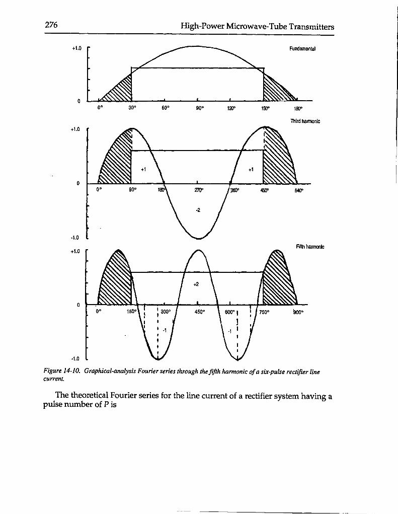
Figure 14-10. Graphical-analysis Fourier series through the fijlh harmonic of a six-pulse rectifier linecurrent.
The theoretical Fourier series for the line current of a rectifier system having apulse number of P is
High-Voltage AC/DC Conversion or Rectification (14) 277
l=sinax+1 1
—sin(P – I)cot+P–1
—sin(P + I)OtP+l
1+
1—sin(2P – l)cot +2P-1
—sin(2P+l)avK2P+1
+’1
—sin(nP – I)@t + —sin(nP + l)ax.nP–1 nP+l
Note that the line-current harmonic components are the odd values just belowand above the rectifier-output harmonic components. For instance, a six-pulserectifier would have a theoretical first ripple component of the sixth harmonic,while the first line-current harmonics would be the fifth and seventh. For thosewho might wish to see a very simple-minded proof that requires no mathematicsat all, Fig. 1410 illustrates this phenomenon for the line current due to the wye-connected secondary winding. If we disregard the coefficients and concentrateon the harmonic-component ratios, a Fourier series is evaluated by multiplyingthe subject waveform by all of the harmonically related sine and cosine wave-forms (in-phase and quadrature). Assigning a value of unity to the line current,the fundamental can be seen to be a sine-wave segment from 30° to 150°. Thethird harmonic sine wave is multiplied by zero between 0° and 90° and againbetween 450° and 540°. For the remainder, just using the similar shapes, there aretwo positive quarter-cycles (+1) and one negative half-cycle (-2), which cancel, sothere is no 3rd harmonic component. (If we trace out the cosine waveforms, wecan easily see that they all cancel to zero.) The fifth harmonic sine wave, how-ever, has non-zero product between 150° and 750°. In the center, two negativequarter-cycles cancel the one positive half-cycle and the two positive and nega-tive 30° segments at the two ends cancel each other. What is left is two negativesegments, one from 210° to 270° and the other from 630° to 690°. If they arepushed together, they have the same wave shape as the fundamental component,except they take up 1/5 of the area.
If one does the same “matMess” analysis of the primary current due to thedelta-comected secondary, the same wave shape emerges for the fifth harmonic.But it is positive instead of negative, so it would cancel the fifth harmonic com-ponent due to the wye-connected secondary in the 12-pulse rectifier. As thepulse number of the rectifier is increased, it can be seen that the line currentbecomes less and less polluted by harmonics and increasingly resembles in shapea fundamental-frequency sine wave.
14.7 Who cares about harmonic pollution?The electrical power utilities certainly care about harmonic pollution. In the
first place, they do not get paid for the current it represents, but they do have tosuffer the power loss it causes. Furthermore, “trapped” resonances at the har-monic frequencies can cause all manner of electrical mischief in terms of resonantovervoltage. And from almost from the beginning of the electrical age, the abilityof power-line harmonics to affect other electrical services has been noted.
The telephone company, whose wires parallel those of the power company in
278 High-Power Microwave-Tube Transmitters
18,000
16,000
14,000
12,000
10,IXM
6,000
6,0C0
4,000
2,000
0
1919
0 600 1600 2400 m 4000 4600
Frequency (Hz)
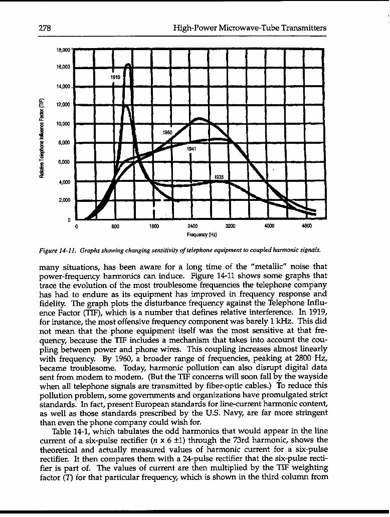
Figure 14-11. Graphs showing changing sensitivity of telephone equipment to coupled hmnonic signals.
many situations, has been aware for a long time of the “metallic” noise thatpower-frequency harmonics can induce. Figure 1411 shows some graphs thattrace the evolution of the most troublesome frequencies the telephone companyhas had to endure as its equipment has improved in frequency response andfidelity. The graph plots the disturbance frequency against the Telephone Influ-ence Factor (’ITF), which is a number that defines relative interference. In 1919,for instance, the most offensive frequency component was barely 1 kHz. This didnot mean that the phone equipment itself was the most sensitive at that fr-equency, because the TIF includes a mechanism that takes into account the cou-pling between power and phone wires. This coupling increases almost linearlywith frequency. By 1960, a broader range of frequencies, peaking at 2800 Hz,became troublesome. Today harmonic pollution can also disrupt digital datasent from modem to modem. (But the TIF concerns will soon fall by the waysidewhen all telephone signals are transmitted by fiber-optic cables.) To reduce thispollution problem, some governments and organizations have promulgated strictstandards. In fact, present European standards for line-current harmonic content,as well as those standards prescribed by the U.S. Navy, are far more stringentthan even the phone company could wish for.
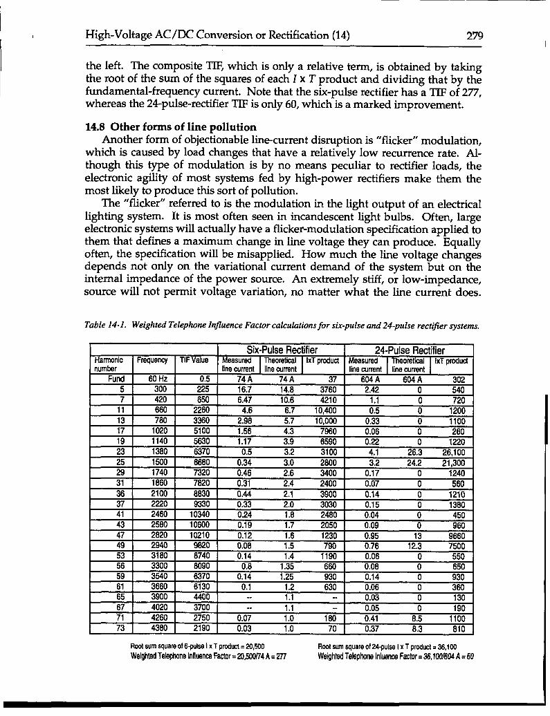
Table 14-1, which tabulates the odd harmonics that would appear in the linecurrent of a six-pulse rectifier (YZx 6 *1) through the 73rd harmonic, shows thetheoretical and actually measured values of harmonic current for a six-pulserectifier. It then compares them with a 24pulse rectifier that the six-pulse recti-fier is part of. The values of current are then multiplied by the TIF weightingfactor (T) for that particular frequency which is shown in the third column from
t
High-Voltage AC/DC Conversion or Rectification (14) 279I
the left. The composite T@, which is only a relative term, is obtained by takingthe root of the sum of the squares of each I x T product and dividing that by thefundamental-frequency current. Note that the six-pulse rectifier has a TIF of 277,whereas the 24-pulse-rectifier TIF is only 60, which is a marked improvement.
14.8 Other forms of line pollutionAnother form of objectionable line-current disruption is “flicker” modulation,
which is caused by load changes that have a relatively low recurrence rate. ALthough this type of modulation is by no means peculiar to rectifier loads, theelectronic agility of most systems fed by high-power rectifiers make them themost likely to produce this sort of pollution.
The “flicker” referred to is the modulation in the light output of an electricallighting system. It is most often seen in incandescent light bulbs. Often, largeelectronic systems will actually have a flicker-modulation specification applied tothem that defines a maximum change in line voltage they can produce. Equallyoften, the specification will be misapplied. How much the line voltage changesdepends not only on the variational current demand of the system but on theinternal impedance of the power source. An extremely stiff, or low-impedance,source will not permit voltage variation, no matter what the line current does.
Table 14-1. Weighted Telephone In.uence Factor calcuhtions for six-pulse and 24-pulse rectifier systems.
Six-Pulse Rectifier 24-Pulse RectifierHarmonic Frequency TIF Value Measured IxT producl Measured Theoretical IxT prOdUCtnumber line current line current
Root sum square of 6-pulsa I x T prcduct = 20,500 Root SUMsquare of 24-pulss I x T product = 36,100Weighted Te!aphoneInfluancaFactor=20,540/74A. 277 Weghtsd Td@rms klklSnCSFactor= 36,100/604A =60
~1Inthite ‘------A ~ ~- ;g;g~A~ ~ 3 2“1 ‘Akse I ~- ----- ---SoUrca Power rfle
Inductlca ragulator Rectifiar transforrrier(z-o) I
I I!
L-t ~Tiivaiyklgtotal toad
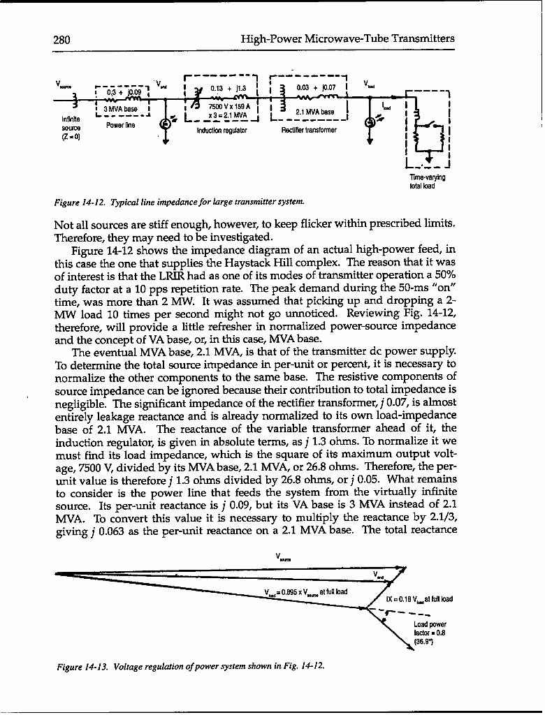
Figure 14-12. Typical line impedance for large transmitter system.
Not all sources are stiff enough, however, to keep flicker within prescribed limits.Therefore, they may need to Fe investigated. -
Figure 14-12 shows the impedance diagram of an actual high-power feed, inthis case the one that supplies the Haystack Hill complex. The reason that it wasof interest is that the LR.IR had as one of its modes of transmitter operation a 50%duty factor at a 10 pps repetition rate. The peak demand during the 50-ms “on”time, was more than 2 MW. It was assumed that picking up and dropping a 2-MW load 10 times per second might not go unnoticed. Reviewing Fig. 14-12,therefore, will provide a little refresher in normalized power-source impedanceand the concept of VA base, or, in this case, MVA base.
The eventual MVA base, 2.1 MVA, is that of the transmitter dc power supply.To determine the total source impedance in per-unit or percent, it is necessary tonormalize the other components to the same base. The resistive components ofsource impedance can be ignored because their contribution to total impedance isnegligible. The significant impedance of the rectifier transformer, j 0.07, is almostentirely leakage reactance and is already normalized to its own load-impedancebase of 2.1 WA. The reactance of the variable transformer ahead of it, theinduction regulator, is given in absolute terms, as j 1.3 ohms. To normalize it wemust find its load impedance, which is the square of its maximum output volt-age, 7500 V, divided by its MVA base, 2.1 MVA, or 26.8 ohms. Therefore, the per-unit value is therefore j 1.3 ohms divided by 26.8 ohms, or j 0.05. What remainsto consider is the power line that feeds the system from the virtually infinitesource. Its per-unit reactance is j 0.09, but its VA base is 3 MVA instead of 2.1MVA. To convert this value it is necessary to multiply the reactance by 2.1/3,giving j 0.063 as the per-unit reactance on a 2.1 MVA base. The total reactance
v_
l)(=&18Vwatfull load
Figure 14-13. Voltage regulation of power system shown in Fig. 14-12.
High-Voltage AC/DC Conversion or Rectification (14) 281
4
3
2
1
0
6
5
. sFiuctuaticwlwur
QFluctuaticdminute Fluctuationa/second
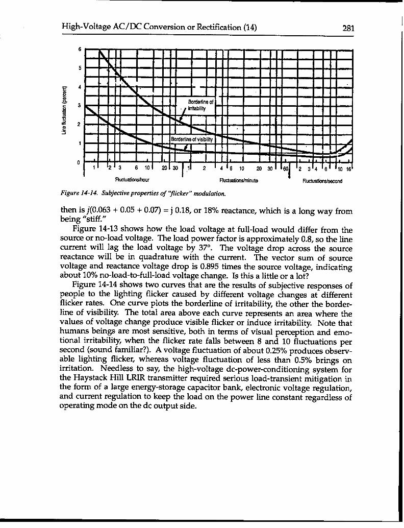
Figure 14-14. Subjective properties of “flicker” modulation.
then is j(O.063 + 0.05 + 0.07) = j 0.18, or 18% reactance, which is a long way frombeing “stiff.”
Figure 1413 shows how the load voltage at full-load would differ from thesource or no-load voltage. The load power factor is approximately 0.8, so the linecurrent will lag the load voltage by 37°. The voltage drop across the sourcereactance will be in quadrature with the current. The vector sum of sourcevoltage and reactance voltage drop is 0.895 times the source voltage, indicatingabout 10% no-load-to-full-load voltage change. Is this a little or a lot?
Figure 14-14 shows two curves that are the results of subjective responses ofpeople to the lighting flicker caused by different voltage changes at differentflicker rates. One curve plots the borderline of irritability, the other the border-line of visibility. The total area above each curve represents an area where thevalues of voltage change produce visible flicker or induce irritability. Note thathumans beings are most sensitive, both in terms of visual perception and emo-tional irritability., when the flicker rate falls between 8 and 10 fluctuations persecond (sound familiar?). A voltage fluctuation of about 0.25% produces observ-able lighting flicker, whereas voltage fluctuation of less than 0.5% brings onirritation. Needless to say, the high-voltage de-power-conditioning system forthe Haystack Hill LRIR transmitter required serious load-transient mitigation inthe form of a large energy-storage capacitor bank, electronic voltage regulation,and current regulation to keep the load on the power line constant regardless ofoperating mode on the dc output side.