25
2015 World Radiocommunication Conference Agenda Items Affecting EESS (active) May 29, 2014 Committee On Radio Frequencies Thomas vonDeak NASA Spectrum Office • 1
| Date post: | 28-Dec-2015 |
| Category: |
Documents |
| Upload: | barbara-daniel |
| View: | 215 times |
| Download: | 0 times |
2015 World Radiocommunication Conference Agenda Items
Affecting EESS (active)May 29, 2014
Committee On Radio Frequencies
Thomas vonDeakNASA Spectrum Office
• 1
Overview
2
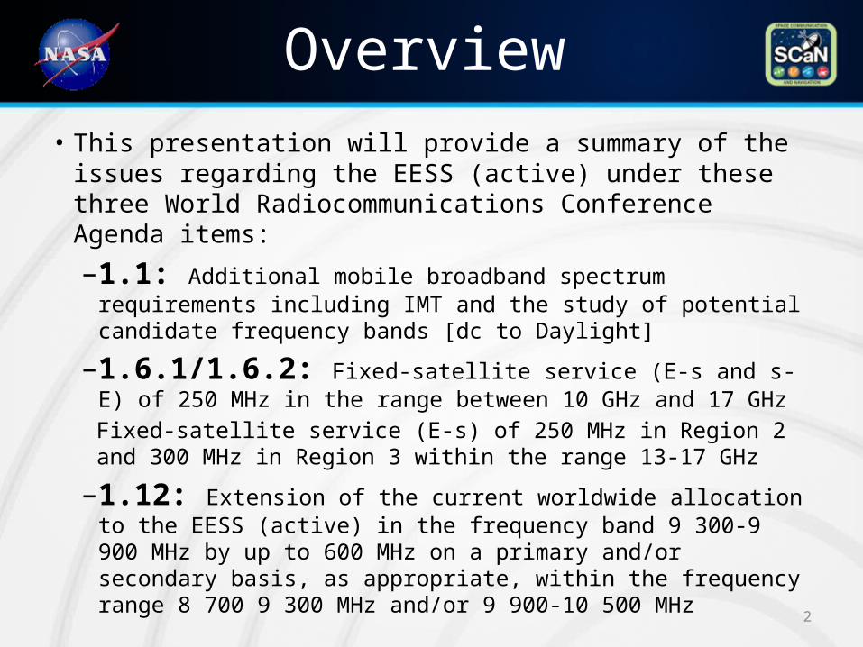
• This presentation will provide a summary of the issues regarding the EESS (active) under these three World Radiocommunications Conference Agenda items:
–1.1: Additional mobile broadband spectrum requirements including IMT and the study of potential candidate frequency bands [dc to Daylight]
–1.6.1/1.6.2: Fixed-satellite service (E-s and s-E) of 250 MHz in the range between 10 GHz and 17 GHz Fixed-satellite service (E-s) of 250 MHz in Region 2 and 300 MHz in Region 3 within the range 13-17 GHz
–1.12: Extension of the current worldwide allocation to the EESS (active) in the frequency band 9 300-9 900 MHz by up to 600 MHz on a primary and/or secondary basis, as appropriate, within the frequency range 8 700 9 300 MHz and/or 9 900-10 500 MHz
WRC-15 Agenda item 1.1
3
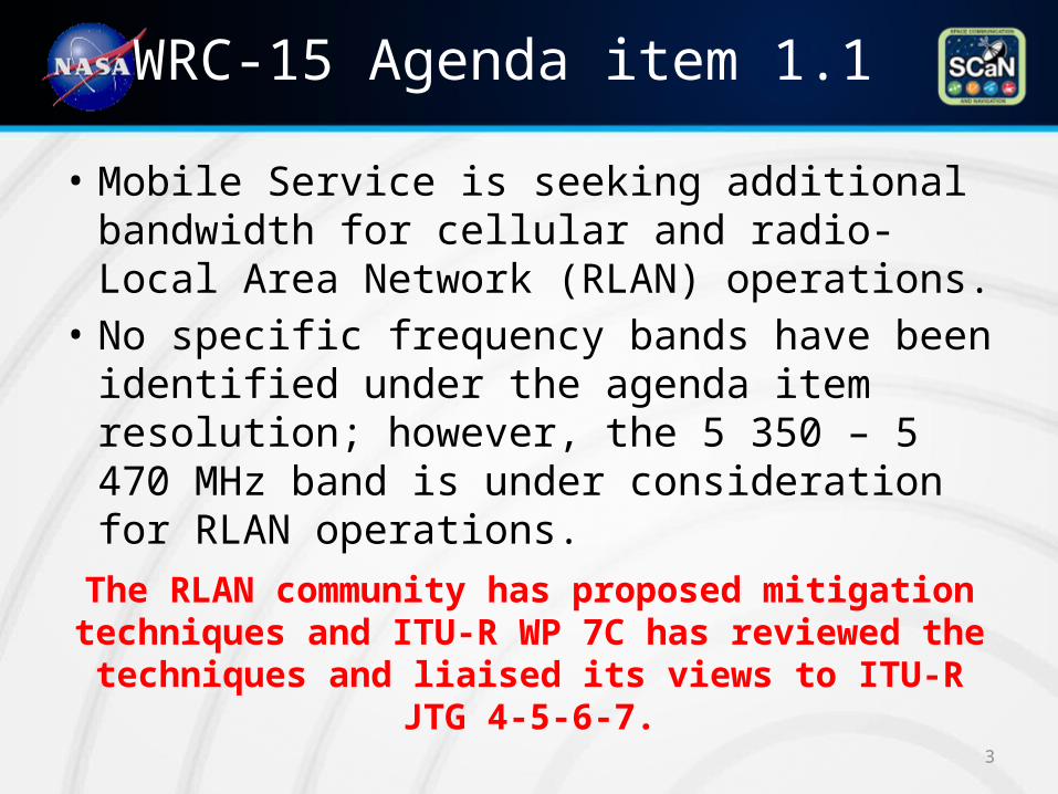
• Mobile Service is seeking additional bandwidth for cellular and radio-Local Area Network (RLAN) operations.
• No specific frequency bands have been identified under the agenda item resolution; however, the 5 350 – 5 470 MHz band is under consideration for RLAN operations.
The RLAN community has proposed mitigation techniques and ITU-R WP 7C has reviewed the
techniques and liaised its views to ITU-R JTG 4-5-6-7.
Proposed Mitigation techniques
4
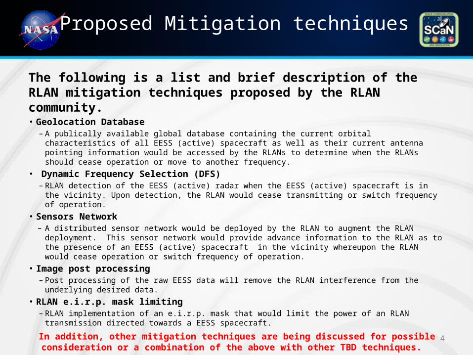
The following is a list and brief description of the RLAN mitigation techniques proposed by the RLAN community.• Geolocation Database
– A publically available global database containing the current orbital characteristics of all EESS (active) spacecraft as well as their current antenna pointing information would be accessed by the RLANs to determine when the RLANs should cease operation or move to another frequency.
• Dynamic Frequency Selection (DFS)– RLAN detection of the EESS (active) radar when the EESS (active) spacecraft is in the vicinity. Upon
detection, the RLAN would cease transmitting or switch frequency of operation. • Sensors Network
– A distributed sensor network would be deployed by the RLAN to augment the RLAN deployment. This sensor network would provide advance information to the RLAN as to the presence of an EESS (active) spacecraft in the vicinity whereupon the RLAN would cease operation or switch frequency of operation.
• Image post processing– Post processing of the raw EESS data will remove the RLAN interference from the underlying desired
data.• RLAN e.i.r.p. mask limiting
– RLAN implementation of an e.i.r.p. mask that would limit the power of an RLAN transmission directed towards a EESS spacecraft.
In addition, other mitigation techniques are being discussed for possible consideration or a combination of the above with other TBD techniques.
ITU-R Working Party 7C views
5
• Geolocation Database– Database source issues: No organization exists that has a
database of EESS (active) sensor orbital characteristics.• NORAD (U.S. Stratcomm) nor the ITU Space Networks System is
comprehensive enough.
– Oversight concerns: Maintenance of such a database would require international overview and will have to be developed and maintained by a suitable international organisation.
– One size doesn’t fit all: The orbital characteristics are different among different types of EESS (active) sensors (SAR, altimeters, scatterometers, ...).
– EESS antenna pointing: The instantaneous antenna pointing of the EESS (active) sensors is not available in any database nor is it likely to be made available by all EESS (active) operators.
Many other concerns outside the expertise of WP 7C were expessed regarding this technique, such as hacking, IP tampering, and enforcement were also noted.
ITU-R Working Party 7C views
6
• Dynamic Frequency Selection (DFS)– Latency problem: The detection would occur during an EESS (active)
illumination of the area and interference to the EESS (active) would already have occurred. Regardless of the detection level used by the RLAN DFS this latency would render the technique ineffective in mitigating interference to the EESS (active) sensor.
• Sensors Network – Non-continuous SAR operations: SAR systems do not operate in a
continuous manner and so when the sensor initiate operation may immediately encounter interference under this technique.
– RLAN sensors in the ocean?: Measurements on coastal areas would be impacted since it is unlikely that RLAN sensors would be deployed in open water.
– Sensor network latency: The speed of the EESS (active) sensor (7 km/sec) would require the RLAN sensor network to be prohibitively large and details describing the coordination of the RLAN sensor network and RLAN switch operation are absent.
– Enforcement: Enforcement of the proper operation of the sensor network is also a concern.
ITU-R Working Party 7C views
7
• Image post processing– Never perfect: This technique always results in a reduction of its
radiometric quality. – Non-universal: The post-processing algorithms under study do not work
for the case of interferometric SAR measurements. – Single well behaved interferer dependent: Post-processing algorithms
are only be effective when the interference is from a single source generating a coherent pulsed signal .• RLAN interference seen by the SAR would be the composite of many different
RLAN signals from multiple RLAN devices in the SAR footprint. These devices will not generate signals that are coherent among them.
• RLAN e.i.r.p. mask limitingIn theory an e.i.r.p. mask concept could work; however:– Enforcement: Questions the means to correctly implement and enforce
an e.i.r.p. mask • Mass market unlicensed devices ‑• RLAN could be ceiling mounted or mounted in different manner (e.g. wall)
– Multipath: Also, a mask on indoor RLAN devices would not necessarily limit emissions towards the satellite • Building multipath etc.
Agenda item 1.6
8
• Fixed Satellite Service (FSS) is seeking additional 250 MHz of uplink bandwidth in the frequency range of 13 - 17 GHz.
• Although the entire 13 - 17 GHz range is under examination only two bands are plausibly viable for consideration: 13.4 - 13.75 GHz and 14.5. - 14.8 GHz.– EESS (active) operates in the 13.4 -13.75 GHz band.
The results of studies performed by NASA will be provided.
Compatibility AnalysisInput parameters
9
Relevant system characteristics• Victim receiver characteristics
– System noise, antenna pattern
• Offending Transmitter characteristics– Power, antenna gain and pointing, deployment characteristics
• Link parameters– Distance separation, shielding
Evaluation Criteria • Victim receiver acceptable limits of interference
(Protection criteria)– Amount of degradation to victim receiver signal that can be tolerated.
(Interference to Noise ratio)– Percentage of time the degradation can be tolerated.
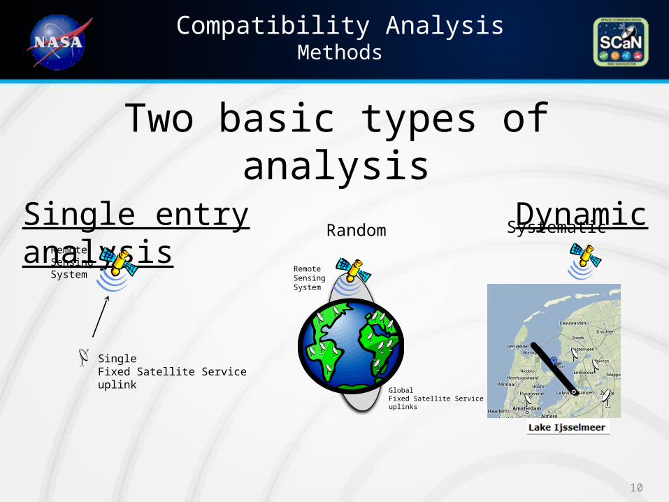
Compatibility AnalysisMethods
10
Two basic types of analysisSingle entry Dynamic analysis
Remote Sensing System
Single Fixed Satellite Service uplink
Remote Sensing System
GlobalFixed Satellite Service uplinks
Random Systematic
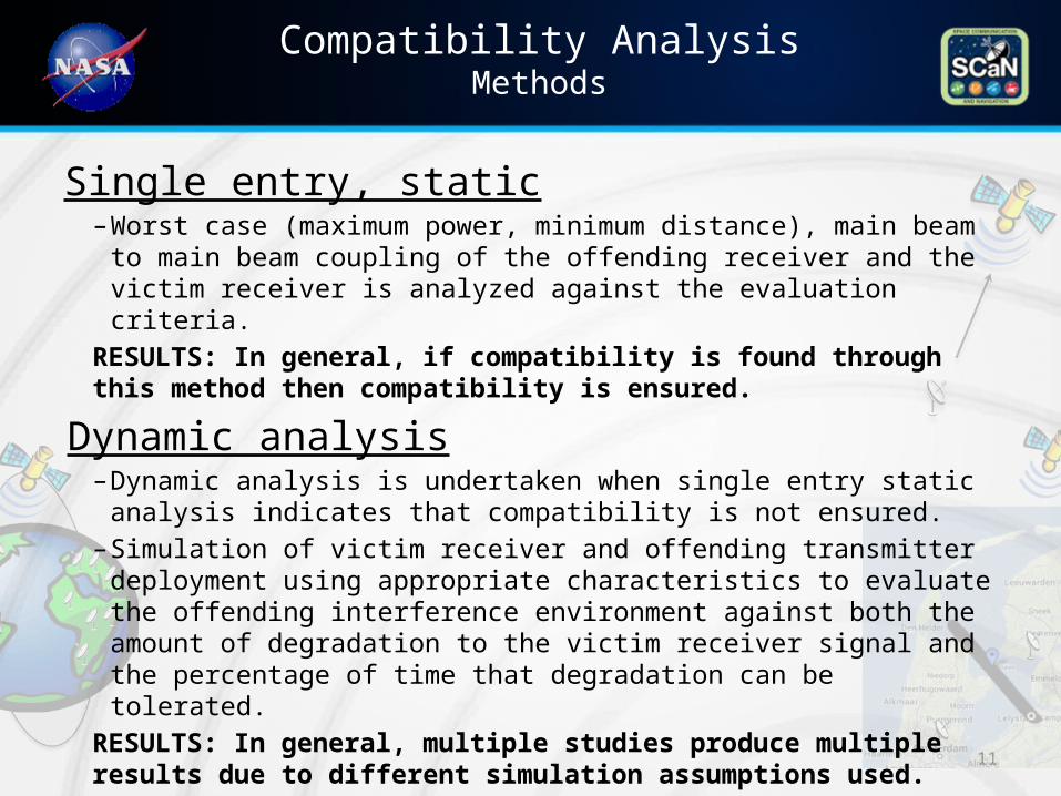
Compatibility AnalysisMethods
11
Single entry, static– Worst case (maximum power, minimum distance), main beam to
main beam coupling of the offending receiver and the victim receiver is analyzed against the evaluation criteria.
RESULTS: In general, if compatibility is found through this method then compatibility is ensured.
Dynamic analysis– Dynamic analysis is undertaken when single entry static analysis
indicates that compatibility is not ensured.– Simulation of victim receiver and offending transmitter deployment
using appropriate characteristics to evaluate the offending interference environment against both the amount of degradation to the victim receiver signal and the percentage of time that degradation can be tolerated.
RESULTS: In general, multiple studies produce multiple results due to different simulation assumptions used.
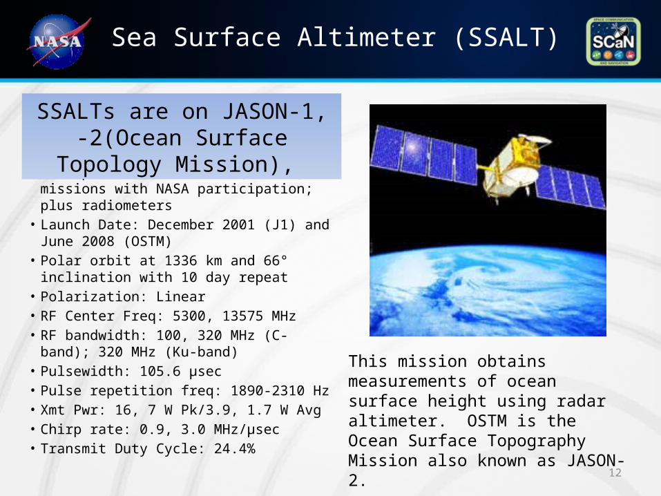
Sea Surface Altimeter (SSALT)
• All spacecraft are CNES (France) missions with NASA participation; plus radiometers
• Launch Date: December 2001 (J1) and June 2008 (OSTM)
• Polar orbit at 1336 km and 66° inclination with 10 day repeat
• Polarization: Linear• RF Center Freq: 5300, 13575 MHz• RF bandwidth: 100, 320 MHz (C-band); 320
MHz (Ku-band)• Pulsewidth: 105.6 μsec• Pulse repetition freq: 1890-2310 Hz• Xmt Pwr: 16, 7 W Pk/3.9, 1.7 W Avg• Chirp rate: 0.9, 3.0 MHz/μsec• Transmit Duty Cycle: 24.4% 12
SSALTs are on JASON-1, -2(Ocean Surface Topology Mission),
This mission obtains measurements of ocean surface height using radar altimeter. OSTM is the Ocean Surface Topography Mission also known as JASON-2.
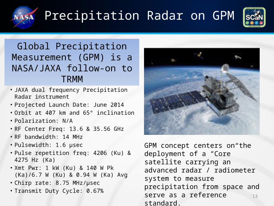
Precipitation Radar on GPM
• JAXA dual frequency Precipitation Radar instrument
• Projected Launch Date: June 2014• Orbit at 407 km and 65° inclination• Polarization: N/A• RF Center Freq: 13.6 & 35.56 GHz• RF bandwidth: 14 MHz• Pulsewidth: 1.6 μsec• Pulse repetition freq: 4206 (Ku) & 4275 Hz
(Ka)• Xmt Pwr: 1 kW (Ku) & 140 W Pk (Ka)/6.7 W
(Ku) & 0.94 W (Ka) Avg• Chirp rate: 8.75 MHz/μsec• Transmit Duty Cycle: 0.67%
13
Global Precipitation Measurement (GPM) is a NASA/JAXA follow-on to
TRMM
GPM concept centers on the deployment of a “Core” satellite carrying an advanced radar / radiometer system to measure precipitation from space and serve as a reference standard.
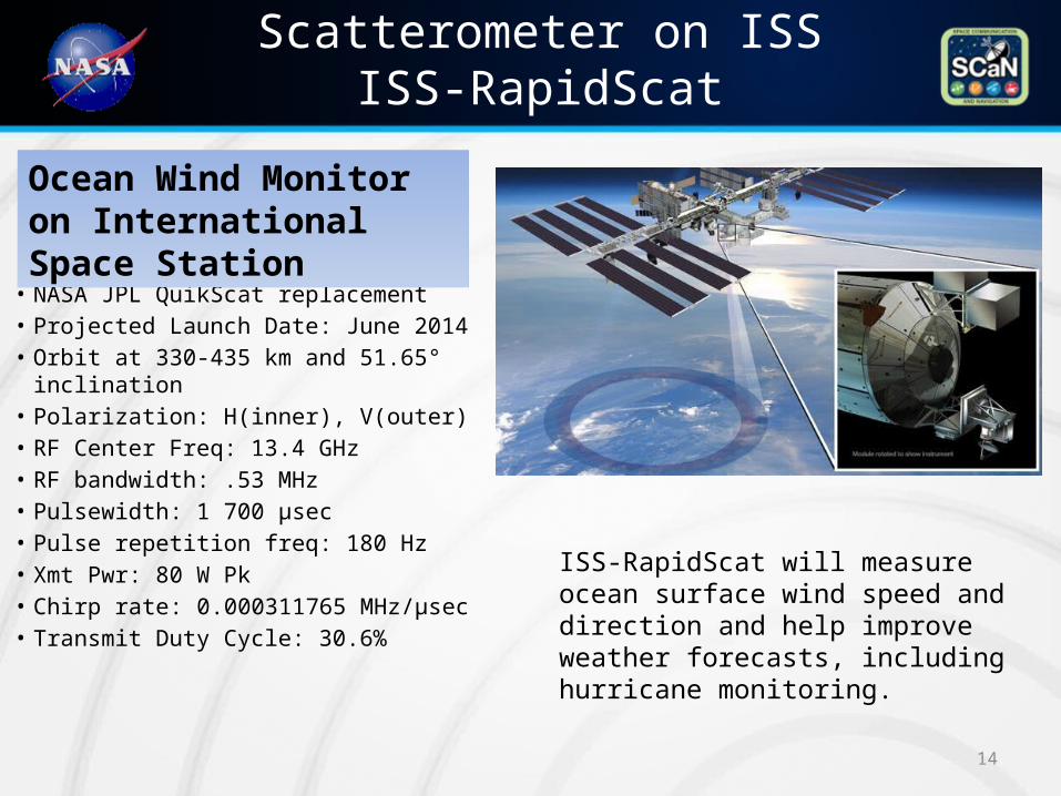
Scatterometer on ISSISS-RapidScat
• NASA JPL QuikScat replacement• Projected Launch Date: June 2014• Orbit at 330-435 km and 51.65°
inclination• Polarization: H(inner), V(outer)• RF Center Freq: 13.4 GHz• RF bandwidth: .53 MHz• Pulsewidth: 1 700 μsec• Pulse repetition freq: 180 Hz• Xmt Pwr: 80 W Pk• Chirp rate: 0.000311765 MHz/μsec• Transmit Duty Cycle: 30.6%
14
Ocean Wind Monitor on International Space Station
ISS-RapidScat will measure ocean surface wind speed and direction and help improve weather forecasts, including hurricane monitoring.
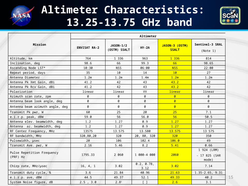
Altimeter Characteristics: 13.25-13.75 GHz band
Mission
Altimeter
ENVISAT RA-2JASON-1/2
(OSTM) SSALT
HY-2AJASON-3 (OSTM)
SSALT
Sentinel-3 SRAL
(Note 1)
Altitude, km 764 1 336 963 1 336 814
Inclination, deg 98.6 66 99.3 66 98.65
Ascending Node LST* 10:30 NSS 06:00 NSS 22:00
Repeat period, days 35 10 14 10 27
Antenna Diameter 1.2m 1.2m 1.4m 1.2m 1.2m
Antenna Pk Xmt Gain, dBi 41.2 42 43 43.2 42
Antenna Pk Rcv Gain, dBi 41.2 42 43 43.2 42
Polarization linear linear VV linear linear
Azimuth scan rate, rpm 0 0 0 0 0
Antenna beam look angle, deg 0 0 0 0 0
Antenna beam azimuth angle, deg 0 0 0 0 0
Transmit Pk pwr, W 60 25 20 25 7.1
e.i.r.p. peak, dBW 59.0 56 56.0 56 50.5
Antenna elev. beamwidth, deg 1.2 1.27 0.9 1.27 1.27
Antenna az. beamwidth, deg 1.2 1.27 0.9 1.27 1.27
RF Center Frequency, MHz 13575 13.575 13.580 13.575 13 575
RF bandwidth, MHz 320,80,20 320 20, 80, 320 320 350
Pulsewidth, μsec 20 106 102.4 106.0 49
Transmit Ave. pwr, W 2.16 5.46 8.2 5.41 0.66
Pulse Repetition Frequency (PRF) Hz 1795.33 2 060 1 000-4 000 20601 924 (LRM)
- 17 825 (SAR mode)
Chirp rate, MHz/μsec 16, 4, 1 3.02 0.2, 0.78, 3.12 3.02 7.14
Transmit duty cycle, % 3.6 21.84 40.96 21.63 1.35-2.65, 9.31
e.i.r.p. ave, dBW 44.5 49.37 52.1 49.33 40.2
System Noise figure, dB 2.5 , 3.0 2.81 [ ] 2.6 3.1 15
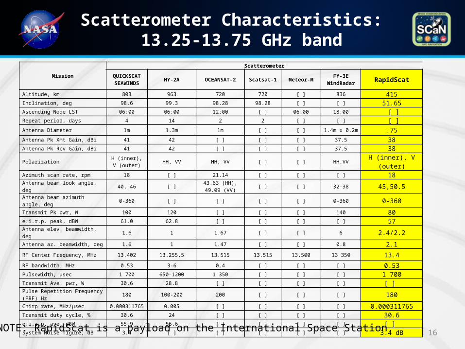
Scatterometer Characteristics: 13.25-13.75 GHz band
16
Mission
Scatterometer
QUICKSCAT SEAWINDS
HY-2A OCEANSAT-2 Scatsat-1 Meteor-MFY-3E
WindRadar RapidScat
Altitude, km 803 963 720 720 [ ] 836 415Inclination, deg 98.6 99.3 98.28 98.28 [ ] [ ] 51.65Ascending Node LST 06:00 06:00 12:00 [ ] 06:00 18:00 [ ]Repeat period, days 4 14 2 2 [ ] [ ] [ ]
Antenna Diameter 1m 1.3m 1m [ ] [ ] 1.4m x 0.2m .75
Antenna Pk Xmt Gain, dBi 41 42 [ ] [ ] [ ] 37.5 38Antenna Pk Rcv Gain, dBi 41 42 [ ] [ ] [ ] 37.5 38
PolarizationH (inner), V
(outer) HH, VV HH, VV [ ] [ ] HH,VV H (inner), V (outer)
Azimuth scan rate, rpm 18 [ ] 21.14 [ ] [ ] [ ] 18
Antenna beam look angle, deg 40, 46 [ ]43.63 (HH), 49.09
(VV) [ ] [ ] 32-38 45,50.5
Antenna beam azimuth angle, deg 0-360 [ ] [ ] [ ] [ ] 0-360 0-360
Transmit Pk pwr, W 100 120 [ ] [ ] [ ] 140 80e.i.r.p. peak, dBW 61.0 62.8 [ ] [ ] [ ] [ ] 57Antenna elev. beamwidth, deg 1.6 1 1.67 [ ] [ ] 6 2.4/2.2Antenna az. beamwidth, deg 1.6 1 1.47 [ ] [ ] 0.8 2.1
RF Center Frequency, MHz 13.402 13.255.5 13.515 13.515 13.500 13 350 13.4
RF bandwidth, MHz 0.53 3-6 0.4 [ ] [ ] [ ] 0.53Pulsewidth, μsec 1 700 650-1200 1 350 [ ] [ ] [ ] 1 700Transmit Ave. pwr, W 30.6 28.8 [ ] [ ] [ ] [ ] [ ]
Pulse Repetition Frequency (PRF) Hz 180 100-200 200 [ ] [ ] [ ] 180
Chirp rate, MHz/μsec 0.000311765 0.005 [ ] [ ] [ ] [ ] 0.000311765Transmit duty cycle, % 30.6 24 [ ] [ ] [ ] [ ] 30.6e.i.r.p. ave, dBW 55.9 56.6 [ ] [ ] [ ] [ ] [ ] System Noise figure, dB 3.4 [ ] [ ] [ ] [ ] [ ] 3.4 dB
NOTE: RapidScat is a payload on the International Space Station.
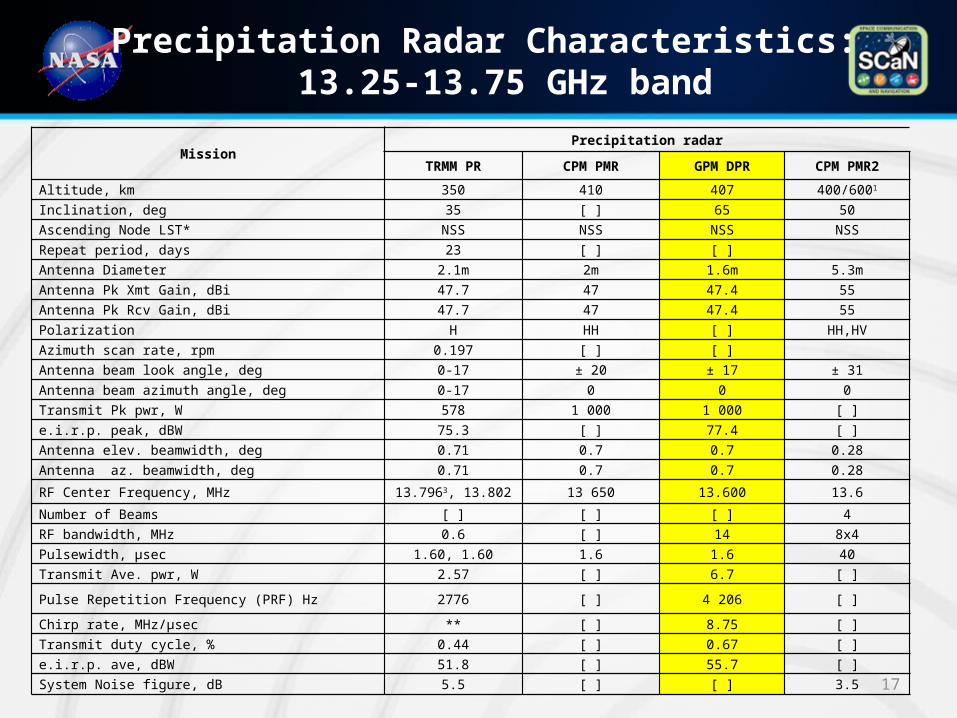
Precipitation Radar Characteristics: 13.25-13.75 GHz band
17
MissionPrecipitation radar
TRMM PR CPM PMR GPM DPR CPM PMR2
Altitude, km 350 410 407 400/6001
Inclination, deg 35 [ ] 65 50
Ascending Node LST* NSS NSS NSS NSS
Repeat period, days 23 [ ] [ ]
Antenna Diameter 2.1m 2m 1.6m 5.3m
Antenna Pk Xmt Gain, dBi 47.7 47 47.4 55
Antenna Pk Rcv Gain, dBi 47.7 47 47.4 55
Polarization H HH [ ] HH,HV
Azimuth scan rate, rpm 0.197 [ ] [ ]
Antenna beam look angle, deg 0-17 ± 20 ± 17 ± 31
Antenna beam azimuth angle, deg 0-17 0 0 0
Transmit Pk pwr, W 578 1 000 1 000 [ ]
e.i.r.p. peak, dBW 75.3 [ ] 77.4 [ ]
Antenna elev. beamwidth, deg 0.71 0.7 0.7 0.28
Antenna az. beamwidth, deg 0.71 0.7 0.7 0.28
RF Center Frequency, MHz 13.7963, 13.802 13 650 13.600 13.6
Number of Beams [ ] [ ] [ ] 4
RF bandwidth, MHz 0.6 [ ] 14 8x4
Pulsewidth, μsec 1.60, 1.60 1.6 1.6 40
Transmit Ave. pwr, W 2.57 [ ] 6.7 [ ]
Pulse Repetition Frequency (PRF) Hz 2776 [ ] 4 206 [ ]
Chirp rate, MHz/μsec ** [ ] 8.75 [ ]
Transmit duty cycle, % 0.44 [ ] 0.67 [ ]
e.i.r.p. ave, dBW 51.8 [ ] 55.7 [ ]
System Noise figure, dB 5.5 [ ] [ ] 3.5
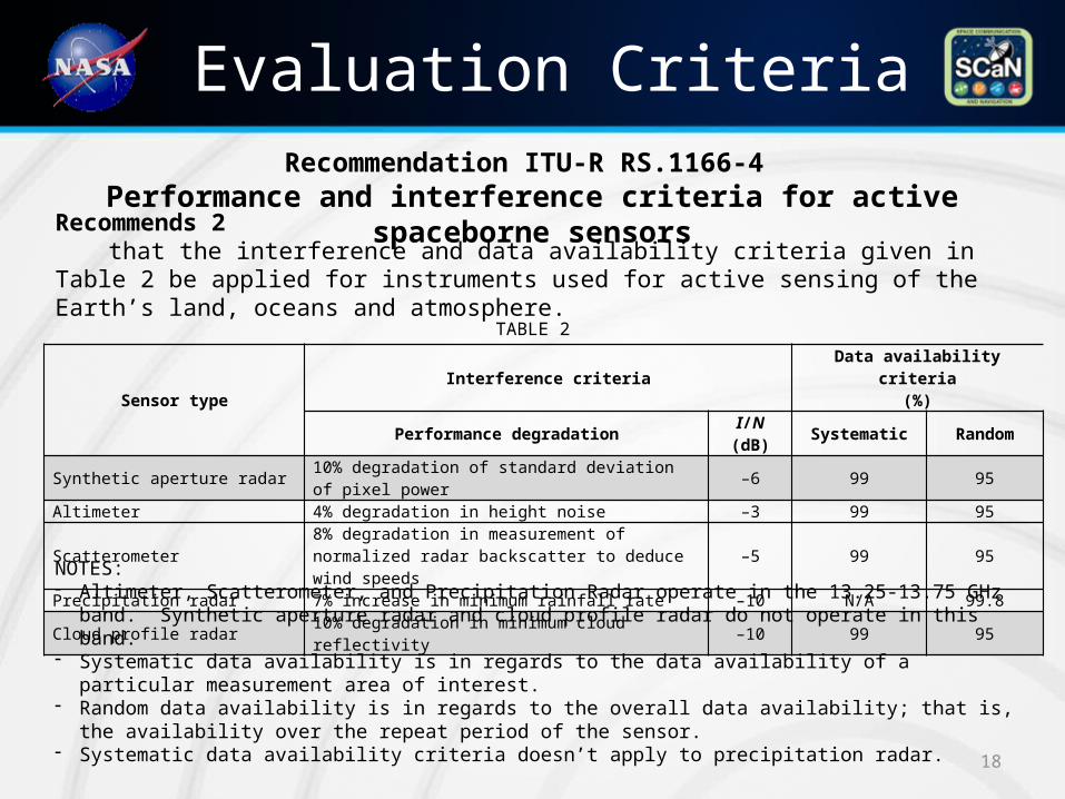
Evaluation Criteria
18
Sensor typeInterference criteria
Data availability criteria(%)
Performance degradationI/N
(dB)Systematic Random
Synthetic aperture radar 10% degradation of standard deviation of pixel power –6 99 95Altimeter 4% degradation in height noise –3 99 95
Scatterometer8% degradation in measurement of normalized radar backscatter to deduce wind speeds –5 99 95
Precipitation radar 7% increase in minimum rainfall rate –10 N/A 99.8Cloud profile radar 10% degradation in minimum cloud reflectivity –10 99 95
Recommends 2that the interference and data availability criteria given in Table 2 be applied for
instruments used for active sensing of the Earth’s land, oceans and atmosphere.
TABLE 2
Recommendation ITU-R RS.1166-4 Performance and interference criteria for active spaceborne sensors
NOTES:- Altimeter, Scatterometer, and Precipitation Radar operate in the 13.25-13.75 GHz band. Synthetic
aperture radar and cloud profile radar do not operate in this band.- Systematic data availability is in regards to the data availability of a particular measurement area of
interest.- Random data availability is in regards to the overall data availability; that is, the availability over the
repeat period of the sensor.- Systematic data availability criteria doesn’t apply to precipitation radar.
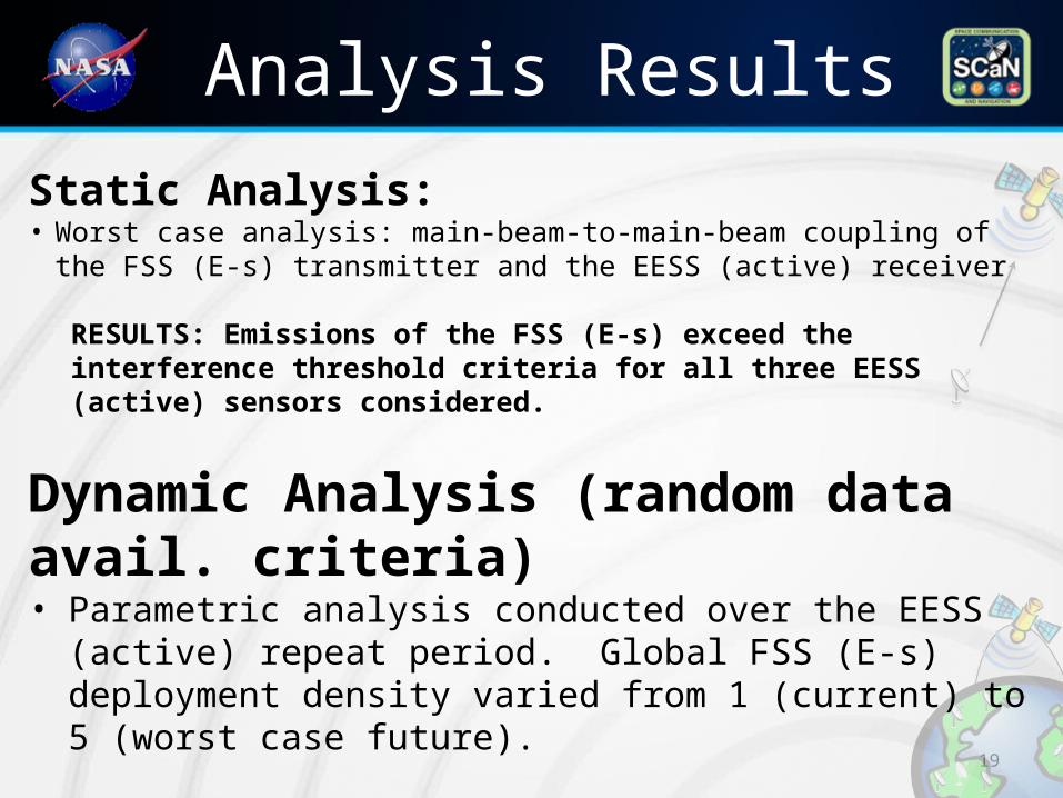
Analysis Results
19
Static Analysis:• Worst case analysis: main-beam-to-main-beam coupling of the
FSS (E-s) transmitter and the EESS (active) receiver
RESULTS: Emissions of the FSS (E-s) exceed the interference threshold criteria for all three EESS (active) sensors considered.
Dynamic Analysis (random data avail. criteria)• Parametric analysis conducted over the EESS (active) repeat period.
Global FSS (E-s) deployment density varied from 1 (current) to 5 (worst case future).
RESULTS: Compatibility is achieved for a FSS deployment density of 1 to 3.
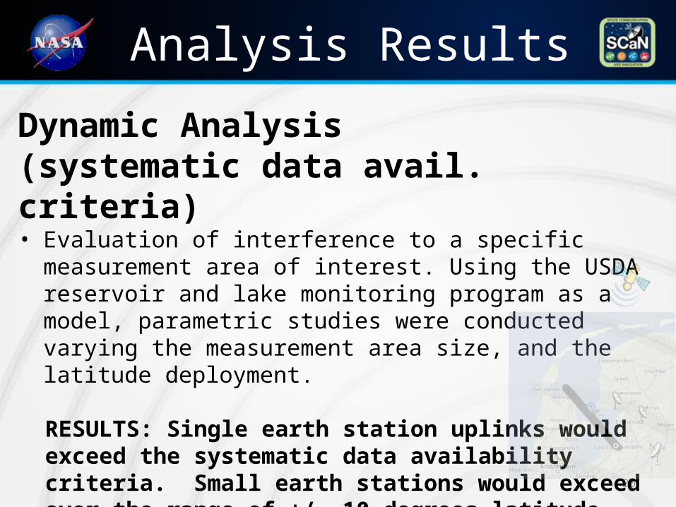
Analysis Results
20
Dynamic Analysis (systematic data avail. criteria)• Evaluation of interference to a specific measurement area of
interest. Using the USDA reservoir and lake monitoring program as a model, parametric studies were conducted varying the measurement area size, and the latitude deployment.
RESULTS: Single earth station uplinks would exceed the systematic data availability criteria. Small earth stations would exceed over the range of +/- 10 degrees latitude. Large earth stations would exceed over the range of +/- 45 latitude.
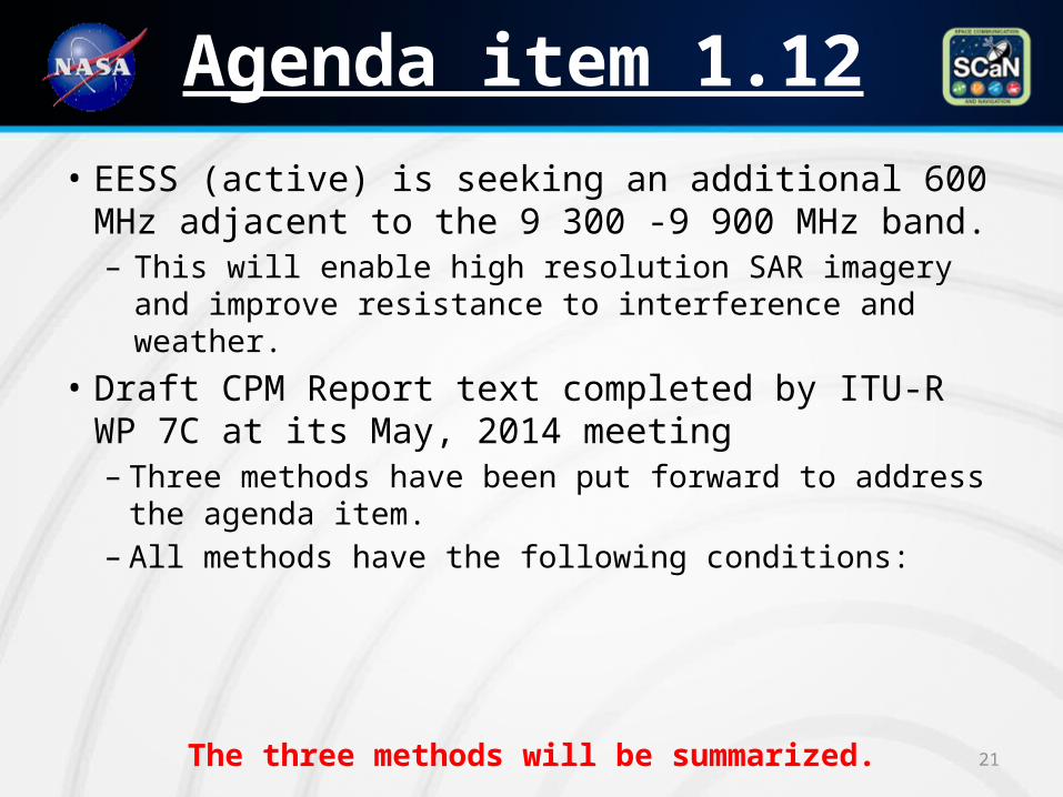
Agenda item 1.12
21
• EESS (active) is seeking an additional 600 MHz adjacent to the 9 300 -9 900 MHz band.– This will enable high resolution SAR imagery and
improve resistance to interference and weather.• Draft CPM Report text completed by ITU-R WP 7C
at its May, 2014 meeting– Three methods have been put forward to address the
agenda item.– All methods have the following conditions:
The three methods will be summarized.
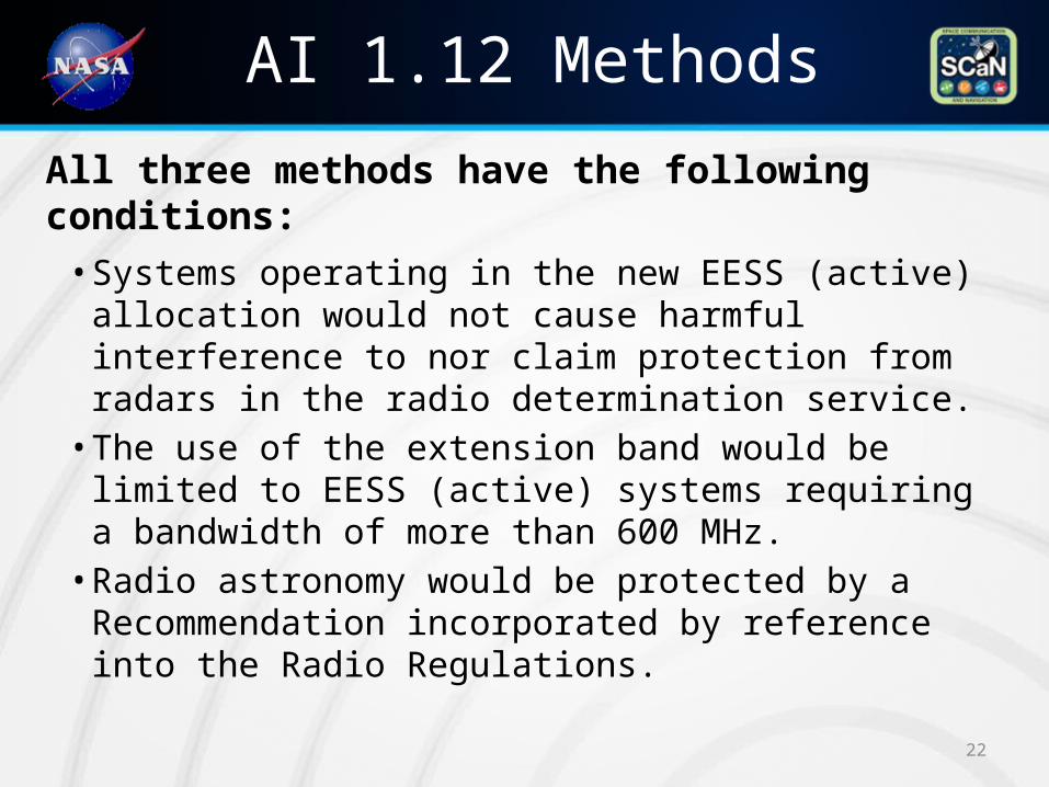
AI 1.12 Methods
All three methods have the following conditions:• Systems operating in the new EESS (active)
allocation would not cause harmful interference to nor claim protection from radars in the radio determination service.• The use of the extension band would be limited to
EESS (active) systems requiring a bandwidth of more than 600 MHz.• Radio astronomy would be protected by a
Recommendation incorporated by reference into the Radio Regulations.
22
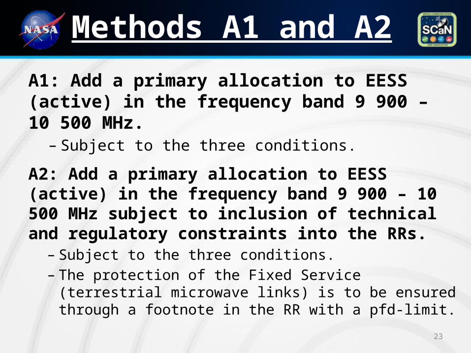
Methods A1 and A2
23
A1: Add a primary allocation to EESS (active) in the frequency band 9 900 – 10 500 MHz. – Subject to the three conditions.
A2: Add a primary allocation to EESS (active) in the frequency band 9 900 – 10 500 MHz subject to inclusion of technical and regulatory constraints into the RRs. – Subject to the three conditions.– The protection of the Fixed Service (terrestrial microwave
links) is to be ensured through a footnote in the RR with a pfd-limit.
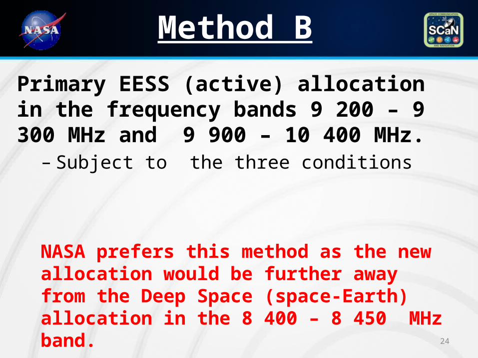
Method B
24
Primary EESS (active) allocation in the frequency bands 9 200 – 9 300 MHz and 9 900 – 10 400 MHz. – Subject to the three conditions
NASA prefers this method as the new allocation would be further away from the Deep Space (space-Earth) allocation in the 8 400 – 8 450 MHz band.
FINI25


