WCCM V Fifth World Congress on Computational Mechanics July 7–12, 2002, Vienna, Austria Eds.: H.A. Mang, F.G. Rammerstorfer, J. Eberhardsteiner A 3-D Finite Element Formulation for the Determination of Unknown Boundary Conditions for Steady Thermoelastic Problems Brian H. Dennis Institute of Environmental Studies University of Tokyo, 7-3-1 Hongo, Bunkyo-ku,Tokyo, Japan 113-8656 e-mail: [email protected]George S. Dulikravich Department of Mechanical and Aerospace Engineering The University of Texas at Arlington, UTA Box 19018, Arlington, TX, U.S.A. 76019-0018 e–mail: [email protected]Shinobu Yoshimura Institute of Environmental Studies University of Tokyo, 7-3-1 Hongo, Bunkyo-ku,Tokyo, Japan 113-8656 e-mail: [email protected]Key words: inverse problems, finite element method, thermoelasticity, ill-posed problems Abstract A 3-D finite element method (FEM) formulation for the detection of unknown boundary conditions in linear steady thermoelastic continuum problems is presented. The present FEM formulation is capable of determining displacements, surface stresses, temperatures, and heat fluxes on the boundaries where such quantities are unknown or inaccessible, provided such quantities are sufficiently over-specified on other boundaries. The method can also handle multiple material domains with ease. A regularized form of the method is also presented. The regularization is necessary for solving problems where the over-specified boundary data contain errors. Several regularization approaches are shown. The inverse FEM method described is an extension of a method previously developed by the authors for 2-D steady thermoelastic inverse problems and 3-D thermal inverse problems. The method is demonstrated for several 3-D test cases involving simple geometries. Several different system solution techniques for sparse rectangular systems are briefly discussed.
Transcript
WCCM VFifth World Congress on
Computational MechanicsJuly 7–12, 2002, Vienna, Austria
Key words: inverse problems, finite element method, thermoelasticity, ill-posed problems
AbstractA 3-D finite element method (FEM) formulation for the detection of unknown boundary conditions inlinear steady thermoelastic continuum problems is presented. The present FEM formulation is capable ofdetermining displacements, surface stresses, temperatures, and heat fluxes on the boundaries where suchquantities are unknown or inaccessible, provided such quantities are sufficiently over-specified on otherboundaries. The method can also handle multiple material domains with ease. A regularized form of themethod is also presented. The regularization is necessary for solving problems where the over-specifiedboundary data contain errors. Several regularization approaches are shown. The inverse FEM methoddescribed is an extension of a method previously developed by the authors for 2-D steady thermoelasticinverse problems and 3-D thermal inverse problems. The method is demonstrated for several 3-D testcases involving simple geometries. Several different system solution techniques for sparse rectangularsystems are briefly discussed.
B. H. Dennis, G. S. Dulikravich, and S. Yoshimura
1 Introduction
It is often difficult or even impossible to place temperature probes, heat flux probes, or strain gauges oncertain parts of a surface of a solid body. This can be due to its small size, geometric inaccessibility,or a exposure to a hostile environment. With an appropriate inverse method these unknown boundaryvalues can be determined from additional information provided at the boundaries where the values canbe measured directly. In the case of steady thermal and elastic problems, the objective of the inverseproblem is to determine displacements, surface stresses, heat fluxes, and temperatures on boundarieswhere they are unknown. The problem of inverse determination of unknown boundary conditions in two-dimensional steady heat conduction has been solved by a variety of methods [1, 2, 3, 4, 5]. Similarly,a separate inverse boundary condition determination problem in linear elastostatics has been solved bydifferent methods [6]. The inverse boundary condition determination problem for steady thermoelasticitywas also solved for several two-dimensional problems [4].
A 3-D finite element formulation is presented here that allows one to solve this inverse problem in a directmanner by over-specifying boundary conditions on boundaries where that information is available. Ourobjective is to develop and demonstrate an approach for the prediction of thermal boundary conditionson parts of a three-dimensional solid body surface by using FEM.
It should be pointed out that the method for the solution of inverse problems to be discussed in this paperis different from the approach based on boundary element method that has been used separately in linearheat conduction [3] and linear elasticity [6].
For inverse problems, the unknown boundary conditions on parts of the boundary can be determinedby overspecifying the boundary conditions (enforcing both Dirichlet and Neumann type boundary con-ditions) on at least some of the remaining portions of the boundary, and providing either Dirichlet orNeumann type boundary conditions on the rest of the boundary. It is possible, after a series of algebraicmanipulations, to transform the original system of equations into a system which enforces the over-specified boundary conditions and includes the unknown boundary conditions as a part of the unknownsolution vector. This formulation is an adaptation of a method used by Martin and Dulikravich [7] for theinverse detection of boundary conditions in steady heat conduction.
Specifically, this work represents an extension of the conceptual work presented by the authors [4, 8] byextending the original formulation from two dimensions into three dimensions.
2 FEM Formulation for Thermoelasticity
The Navier equations for linear static deformations ��������� in three-dimensional Cartesian � �����coordinates are
Here, FHG�I?G3J are body forces per unit volume due to stresses from thermal expansion.
F K L�MONQPSRUTQV�W X�Y[Z]\X�^ (4)
I K L�MONQPSRUTQV�W X�Y[Z]\X`_ (5)
J K L�MONQPSRUTQV�W X�Y[Z]\X�a (6)
This system of differential equations (1)-(3) can be written in the following matrix formb c1dfe M bhgid b c1dOjlkQm L bhgidOj�n�opm W[L jlqpr3m Kts (7)
where the differential operator matrix,b cud
, is defined as
b c1d Kvwwwwwwwx
yy�z s ss yy�{ ss s yy!|yy�{ yy�z syy�| s yy!zs yy!| yy�{
}�~~~~~~~� (8)
and the elastic modulus matrix,bhgid
, is defined as
bhg�d K P�vwwwwwwwx
� L � � � s s s� � L � � s s s� � � L � s s ss s s �������� s ss s s s �������� ss s s s s ��������
}�~~~~~~~� (9)
Casting the system of equations (7) in integral form using the weighted residual method yields��� bh�)d b c1d e M bhgid b c1dOjlkQm L bhgidOj�n�o�m W����UL ��� bh��dOjlqpr�m ���9Kts (10)
where the matrix,bh��d
, is the weight matrix which is a collection of test functions.
bh�)d K vx�� � s ss � � ss s ���}� (11)
One should now integrate (10) by parts to get the weak form of (7)� � M b cud bh�)d e W e bhg�d b cudOjlk�m ���'L � � M b c1d bh�)d e W e bhg�dOj�nlo�m ���L � � bh�)dOjlqpr3m ���UL ����� bh�)dOj��)m ����Kts (12)
wherej���m
is the vector of surface tractions on surface � � .j��)m K b ��d bhgid b c1dOjlkQm(13)
3
B. H. Dennis, G. S. Dulikravich, and S. Yoshimura
The matrix � �� contains the Cartesian components of the unit vector normal to the surface ¡£¢ . The dis-placement field in the ¤ , ¥ , and ¦ directions can now be represented with approximation functions
Equations (14)-(16) can be rewritten in matrix formÀ ®§ °!Á ²2� ¹ À § °�Á (17)
where � ¹ is the interpolation matrix which contains the trial functions for each equation in the system.Also note that with Galerkin’s method the weight matrix and the interpolation matrix are equal, � ¹ ²�hÂ� fà . If the matrix � Ä� is defined as � Ä� �²7� Å1 � ¹ (18)
then the substitution of the approximation functions (17) into the weak statement (12) creates the weakintegral form for a finite element expressed asÆ�Ç`È � Ä� à �hÉ� � Ä� À § °�Á4Ê�ËA°uÌ Æ�Ç�È � Ä� à �hÉ� À�Í °Î�Á4Ê�ËÏ°
Ì Æ�Ç È � ¹ à ÀlÐ °Ñ Á4Ê�ËÏ°?Ì Æ�Ò È Ó � ¹ à À�Ô °�Á4Ê ¡ ° ²tÕ (19)
This can also be written in the matrix form as
� Ö ° À § °�Á ² ÀlÐ °�Á(20)
For thermal stresses, the initial elemental strain vector,Í °Î ª becomesÀ�Í °Î Á ²Ø×iÙÛÚ]Ü Ù[Ú]Ü ÙÛÚÝÜ Õ Õ ÕßÞ Ã (21)
The local stiffness matrix, � Ö ° , and the force per unit volume vector,ÀlÐ ° Á
, are determined for eachelement in the domain and then assembled into the global system
� Öà À § Á ² À�á Á(22)
After applying boundary conditions, the global displacements are found by solving this system of linearalgebraic equations. The stresses,
À�â Á, can then be found in terms of the displacements,
À § ÁÀ�â Á ²2�hÉi � Å1 À § ÁãÌ �hÉi À�Í Î Á (23)
4
WCCM V, July 7–12, 2002, Vienna, Austria
3 FEM Formulation for the Thermal Problem
The temperature distribution throughout the domain can be found by solving Poisson’s equation forsteady linear heat conduction with a distributed steady heat source function, Q, and thermal conductivitycoefficient, k. ä-åçæ�è±é�êè�ë éHì è±é�êè`í éîì è±é!êè�ï éñðuòôó (24)
Applying the method of weighted residuals to (24) over an element results inõ�ö`÷ æ�è é êè`ë é ì è é êè�í é ì è é êè±ï é ä ó å ð øEù�úÏûEòtü (25)
Integrating this by parts once (25) creates the weak statement for an elementä õ�ö ÷ åçæ è øè�ë è�êè�ë ì è øè�í èêè`í ì è øè�ï èêè±ï ð�ù�ú ûò õ�ö`÷ý�þ óßù�úÏû ä õ�ÿ�÷±ý�þ æ�� ���� ð�ù�úÏû (26)
Variation of the temperature across an element can be expressed byê æ ë � í � ï ð��ê û æ ë � í � ï ðò �� þ� �� ý�þ æ ë � í � ï ð ê þ(27)
Using Galerkin’s method, the weight function ø and the interpolation function forê
are chosen to be thesame.By defining the matrix � ��� as
the weak statement (26) can be written in the matrix form as� + û, �.- ê û�/�ò - ó�û�/ (29)
where � + û, � ò õ ö ÷ å � ���102� ��� ù�ú û (30)- ó û / ò ä õ�ö`÷ ó - ý /4ù�ú-ì õ�ÿ�÷ ��3 - ý /4ù54 û (31)
The local stiffness matrix, � + û, � � and heat flux vector, - ó û / , are determined for each element in thedomain and then assembled into the global system� + , �.- ê /iò - ó6/ (32)
5
B. H. Dennis, G. S. Dulikravich, and S. Yoshimura
Direct and Inverse Formulations
The above equations for steady thermoelasticity were discretized by using a Galerkin’s finite elementmethod. This results in two linear systems of algebraic equations7 8:9.; <>=�?@;�A6=CB7 8EDF9.;HG�=I?@;HJ6=
(33)
The system is typically large, sparse, symmetric, and positive definite. Once the global system has beenformed, the boundary conditions are applied. For a well-posed analysis (direct) problem, the boundaryconditions must be known on all boundaries of the domain. For heat conduction, either the temperature,GLKNM
or the heat flux,J�KNM
must be specified at each point of the boundary.
For an inverse problem, the unknown boundary conditions on parts of the boundary can be determinedby over-specifying the boundary conditions (enforcing both Dirichlet and Neumann type boundary con-ditions) on at least some of the remaining portions of the boundary, and providing either Dirichlet orNeumann type boundary conditions on the rest of the boundary. It is possible, after a series of algebraicmanipulations, to transform the original system of equations into a system which enforces the over-specified boundary conditions and includes the unknown boundary conditions as a part of the unknownsolution vector. As an example, consider the linear system for heat conduction on a tetrahedral finiteelement with boundary conditions given at nodes 1 and 4.OPPQ
As an example of an inverse problem, one could specify both the temperature,G_KNM
and the heat flux,J�KTM
at node 1, flux only at nodes 2 and 3, and assume the boundary conditions at node 4 as being unknown.The original system of equations (34) can be modified by adding a row and a column correspondingto the additional equation for the over-specified flux at node 1 and the additional unknown due to theunknown boundary flux at node 4. The result isOPPPPPQ
n o o o o8\V]RU8\VTVX8\VTYX8\V^Z o8\Y]RU8\YTVX8\YTYX8\Y^Z o8_Z`RU8_ZNVX8_ZNYX8_ZTZ p n8 RTR 8 RWV 8 RWY 8 R[Z oa)bbbbbc
deeeeef eeeeegG�RGIVGIYGhZJ Z
ijeeeeekeeeeel? deeeeef eeeeeg
GqKJLVJLYoJ Kijeeeeekeeeeel (35)
The resulting systems of equations will remain sparse, but will be non-symmetric and possibly rectangu-lar (instead of squae) depending on the ratio of the number of known to unknown boundary conditions.
4 Regularization
Three regularization methods were applied separately to the solution of the systems of equations in at-tempts to increase the method’s tolerance for measurement errors in the over-specifiedspecified boundaryconditions. Here we consider the regularization of the inverse heat conduction problem.
6
WCCM V, July 7–12, 2002, Vienna, Austria
The general form of a regularized system is given as [9]:rts\uv2wyxhz|{�}h~���� ��� (36)
The traditional Tikhonov regularization is obtained when the damping matrix, � w_�, is set equal to the
identity matrix. Solving (36) in a least squares sense minimizes the following error function.���|�>� ��� {q��~��1� � s\u � zH{�}���z � }��1� ���� �1� v � w\� zH{�}��1� �� (37)
This is the minimization of the residual plus a penalty term. The form of the damping matrix determineswhat penalty is used and the damping parameter,
v, weights the penalty for each equation. These weights
should be determined according to the error associated with the respective equation.
4.1 Method 1
This method of regularization uses a constant damping parameterv
over the entire domain and theidentity matrix as the damping matrix. This method can be considered the traditional Tikhonov method.The penalty term being minimized in this case is the square of the � � norm of the solution vector z&��} .Minimizing this norm will tend to drive the components of z&�"} to uniform values thus producing asmoothing effect. However, minimizing this penalty term will ultimately drive each component to zero,completely destroying the real solution. Thus, great care must be exercised in choosing the dampingparameter
vso that a good balance of smoothness and accuracy is achieved.
4.2 Method 2
This method of regularization uses a constant damping parameterv
only for equations corresponding tothe unknown boundary values. For all other equations
v ~ �and � w\� ~ � � � since the largest errors occur
at the boundaries where the temperatures and fluxes are unknown.
4.3 Method 3
This method uses Laplacian smoothing of the temperatures only on the boundaries where the boundaryconditions are unknown. A penalty term can be constructed such that curvature of the solution on theunspecified boundary is minimized along with the residual.�1� � � {h� ���1� ����¡ _¢�£ (38)
can be thought of as an assembly of linear boundary ele-ments that make up the boundary of the object where the boundary conditions are unknown. The stiffnessmatrix for each boundary element is formed by using a weighted residual method that ensures the Lapla-cian of the solution is minimized over the element. The main advantage of this method is its ability tosmooth the solution vector without necessarily driving the components to zero and away from the truesolution.
7
B. H. Dennis, G. S. Dulikravich, and S. Yoshimura
5 Solution of the Linear System
In general, the resulting FEM systems for the inverse thermal conductivity problems are sparse, unsym-metric, and often rectangular. These properties make the process of finding a solution to the system verychallenging. Three approaches will be discussed here.
The first is to normalize the equations by multiplying both sides by the matrix transpose and solve theresulting square system with common sparse solvers.« ¬:1®�« ¬:.¯H°�±I²³« ¬:1®�¯H´6±
(40)
This approach has been found to be effective for certain inverse problems [10]. The resulting normal-ized system is less sparse than the original system, but it is square, symmetric, and positive definite withapplication of regularization. The normalized system is solved with a direct method (Cholesky or LUfactorization) or with an iterative method (preconditioned Krylov subspace). There are several disadvan-tages to this approach. Among them being the expense of computing
« ¬µ ® « ¬:, the large in-core memory
requirements, and the roundoff error incurred during the« ¬µ ® « ¬:
multiplication.
Another approach is to use iterative methods suitable for non-symmetrical and least squares problems.One such method is the LSQR method, which is an extension of the well-known conjugate gradientmethod [11]. The LSQR method and other similar methods such as the conjugate gradient for leastsquares (CGLS) solve the normalized system, but without explicit computation of
« ¬: ® « ¬µ. However,
convergence rates of these methods depend strongly on the condition number of the normalized systemwhich is roughly the condition number of
« ¬:squared. Convergence can be slow when solving the
systems resulting from the inverse finite element discretization since they are ill-conditioned.
Yet another approach is to use a non-iterative method for non-symmetrical and least squares problemssuch as QR factorization [12] or SVD [13]. However, sparse implementations of QR or SVD solversare needed to reduce the in-core memory requirements for the inverse finite element problems. It isalso possible to use static condensation to reduce the complete sparse system of equations into a densematrix of smaller dimensions [5]. The reduced system involves only the unknowns on the boundary ofthe domain and can be solved efficiently using standard QR or SVD algorithms for dense matrices.
6 Numerical Results
The accuracy and efficiency of the finite element inverse formulation was tested on several simple three-dimensional problems. The method was implemented in an object-oriented finite element code written inC++. Elements used in the calculations were hexahedra with tri-linear interpolation functions. The linearsystems were solved with a sparse QR factorization, The two basic test geometries included an annularcylinder and a cylinder with multiply connected regions.
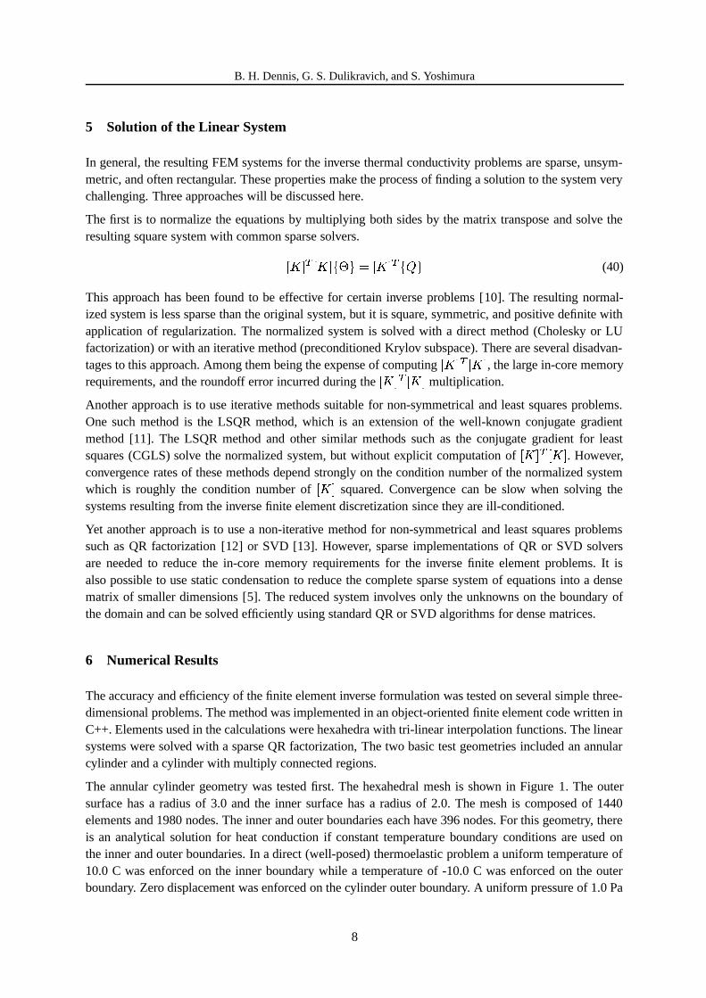
The annular cylinder geometry was tested first. The hexahedral mesh is shown in Figure 1. The outersurface has a radius of 3.0 and the inner surface has a radius of 2.0. The mesh is composed of 1440elements and 1980 nodes. The inner and outer boundaries each have 396 nodes. For this geometry, thereis an analytical solution for heat conduction if constant temperature boundary conditions are used onthe inner and outer boundaries. In a direct (well-posed) thermoelastic problem a uniform temperature of10.0 C was enforced on the inner boundary while a temperature of -10.0 C was enforced on the outerboundary. Zero displacement was enforced on the cylinder outer boundary. A uniform pressure of 1.0 Pa
8
WCCM V, July 7–12, 2002, Vienna, Austria
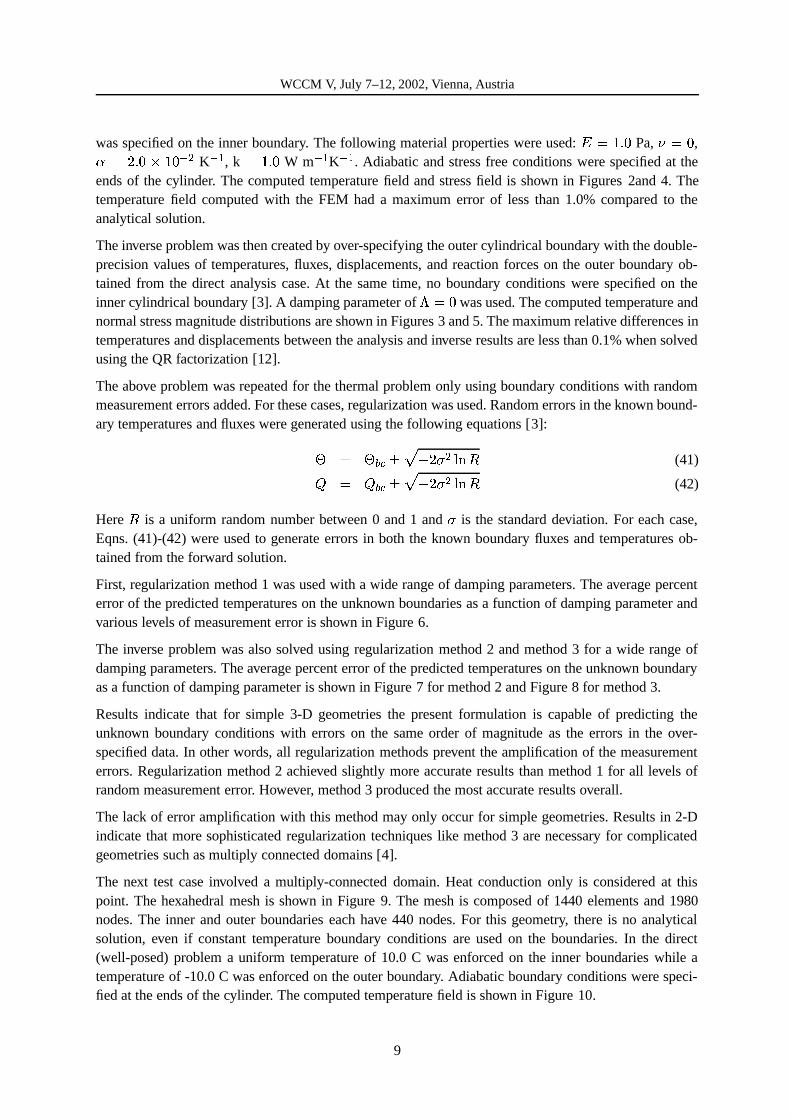
was specified on the inner boundary. The following material properties were used: ¶¸·º¹|»½¼ Pa, ¾:·¿¼ ,À ·ºÁ�»½¼ÃÂ�¹�¼�ÄÆÅ K ÄÈÇ , k ·É¹|»½¼ W m ÄÈÇ K ÄÈÇ . Adiabatic and stress free conditions were specified at theends of the cylinder. The computed temperature field and stress field is shown in Figures 2and 4. Thetemperature field computed with the FEM had a maximum error of less than 1.0% compared to theanalytical solution.
The inverse problem was then created by over-specifying the outer cylindrical boundary with the double-precision values of temperatures, fluxes, displacements, and reaction forces on the outer boundary ob-tained from the direct analysis case. At the same time, no boundary conditions were specified on theinner cylindrical boundary [3]. A damping parameter of Ê˷̼ was used. The computed temperature andnormal stress magnitude distributions are shown in Figures 3 and 5. The maximum relative differences intemperatures and displacements between the analysis and inverse results are less than 0.1% when solvedusing the QR factorization [12].
The above problem was repeated for the thermal problem only using boundary conditions with randommeasurement errors added. For these cases, regularization was used. Random errors in the known bound-ary temperatures and fluxes were generated using the following equations [3]:Í · ÍIÎ.Ï�ÐÒÑ Ó Á|Ô ÅÈÕ�ÖØ× (41)Ù · ÙqÎ.Ï�Ð Ñ Ó Á|Ô ÅÈÕ�ÖØ× (42)
Here × is a uniform random number between 0 and 1 and Ô is the standard deviation. For each case,Eqns. (41)-(42) were used to generate errors in both the known boundary fluxes and temperatures ob-tained from the forward solution.
First, regularization method 1 was used with a wide range of damping parameters. The average percenterror of the predicted temperatures on the unknown boundaries as a function of damping parameter andvarious levels of measurement error is shown in Figure 6.
The inverse problem was also solved using regularization method 2 and method 3 for a wide range ofdamping parameters. The average percent error of the predicted temperatures on the unknown boundaryas a function of damping parameter is shown in Figure 7 for method 2 and Figure 8 for method 3.
Results indicate that for simple 3-D geometries the present formulation is capable of predicting theunknown boundary conditions with errors on the same order of magnitude as the errors in the over-specified data. In other words, all regularization methods prevent the amplification of the measurementerrors. Regularization method 2 achieved slightly more accurate results than method 1 for all levels ofrandom measurement error. However, method 3 produced the most accurate results overall.
The lack of error amplification with this method may only occur for simple geometries. Results in 2-Dindicate that more sophisticated regularization techniques like method 3 are necessary for complicatedgeometries such as multiply connected domains [4].
The next test case involved a multiply-connected domain. Heat conduction only is considered at thispoint. The hexahedral mesh is shown in Figure 9. The mesh is composed of 1440 elements and 1980nodes. The inner and outer boundaries each have 440 nodes. For this geometry, there is no analyticalsolution, even if constant temperature boundary conditions are used on the boundaries. In the direct(well-posed) problem a uniform temperature of 10.0 C was enforced on the inner boundaries while atemperature of -10.0 C was enforced on the outer boundary. Adiabatic boundary conditions were speci-fied at the ends of the cylinder. The computed temperature field is shown in Figure 10.
9
B. H. Dennis, G. S. Dulikravich, and S. Yoshimura
The inverse problem was then created by over-specifying the outer cylindrical boundary with the double-precision values of temperatures and fluxes obtained from the analysis case. At the same time, noboundary conditions were specified on the inner cylindrical boundaries. No errors were used in the over-specified boundary data.
A damping parameter of ÚÜÛÞÝ was tried first. Without regularization, the QR factorization becameunstable due to the high condition number of the linear system.
The same inverse problem was repeated using regularization method 1 for a wide range of dampingparameters. The lowest percent error achieved was 9.97% at damping parameter value of Ú¿Ûàß|áãâ|äSåß�Ý�æÆç . The resulting temperature distribution for ÚËÛ¿ß|áãâ|ä_åèß�ÝÆæÆç is shown in Figure 11.
The inverse problem was also solved using regularization method 2 for a wide range of damping param-eters. The lowest percent error achieved was 2.67% at damping parameter value of Ú³Û�ß|áãâ|äSå�ß�ÝéæÆç .The resulting temperature distribution for Ú�Û¿ß|áãâ|ä_åêß�Ý æÆç is shown in Figure 12.
Finally, the inverse problem was solved using regularization method 3. A value of ÚëÛÜÝìá�ß was usedand percent error compared to the direct solution was less than Ýìá½Ý>Ý>Ýíß�î . The resulting temperaturedistribution is shown in Figure 13.
For the multiply-connected domain case only regularization method 3 worked well. These results indicatethat this FEM inverse method requires regularization that is more sophisticated than the regular Tikonovmethod if high accuracy is needed with multiply-connected three-dimensional geometries.
7 Conclusions
A formulation for the inverse determination of unknown steady boundary conditions in heat conductionand thermoelasticity for three-dimensional problems has been developed using FEM. The formulationhas been tested numerically using an annular geometry with a known analytic solution. The formula-tion can predict the temperatures and displacements on the unknown boundary with high accuracy inthe annular domain without the need for regularization. However, regularization was required in order tocompute a good solution when measurement errors in the over-specified boundary conditions were added.Three different regularization methods were applied. All allow a stable QR factorization to be computed,but only method 3 resulted in highly accurate temperature predictions on the unknown boundaries forlarge values of measurement errors. However, all regularization methods prevented amplification of themeasurement errors. It was shown that the FEM formulation can accurately predict unknown boundaryconditions for multiply-connected domains when a good regularization scheme is used. Further researchis needed to develop better regularization methods so that the present formulation can be made morerobust with respect to measurement errors used with more complex geometries. Further research is alsoneeded to make the current solution procedure more computationally efficient so that thermoelastic in-verse problems for complex 3-D domains can be solved.
Acknowledgements
The primary author would like to acknowledge the support received from the ADVENTURE projectsponsored by the Japanese Society for the Promotion of Science.
10
WCCM V, July 7–12, 2002, Vienna, Austria
References
[1] M. Larsen, An inverse problem: Heat flux and temperature prediction for a high heat flux experi-ment, Tech. rep. SAND-85-2671, Sandia National Laboratories, Albuquerque, NM. (1985).
[2] E. H. Hensel, R. Hills, Steady-state two-dimensional inverse heat conduction, Numerical HeatTransfer, 15, (1989), pp. 227–240.
[3] T. J. Martin, G. S. Dulikravich, Inverse determination of boundary conditions in steady heat con-duction, ASME Journal of Heat Transfer, 3, (1996), pp. 546–554.
[4] B. H. Dennis, G. S. Dulikravich, Simultaneous determination of temperatures, heat fluxes, defor-mations, and tractions on inaccessible boundaries, ASME Journal of Heat Transfer, 121, (1999),pp. 537–545.
[5] L. G. Olson, R. D. Throne, The steady inverse heat conduction problem: A comparison for meth-ods of inverse parameter selection, in 34th National Heat Transfer Conference-NHTC’00, no.NHTC2000-12022, Pittsburg, PA (2000).
[6] T. J. Martin, J. Halderman, G. S. Dulikravich, An inverse method for finding unknown surfacetractions and deformations in elastostatics, Computers and Structures, 56, (1995), pp. 825–836.
[7] T. J. Martin, G. S. Dulikravich, Finding temperatures and heat fluxes on inaccessible surfaces in3-d coated rocket nozzles, in 1995 JANNAF Non-Destructive Evaluation Propulsion SubcommitteeMeeting, Tampa, FL (1995), pp. 119–129.
[8] B. H. Dennis, G. S. Dulikravich, A 3-d finite element formulation for the determination of unknownboundary conditions in heat conduction, in M. Tanaka, ed., Proc. of Internat. Symposium on InverseProblems in Eng. Mechanics, Nagano City, Japan (2001).
[9] A. Neumaier, Solving ill-conditioned and singular linear systems: A tutorial on regularization,SIAM Review, 40, (1998), pp. 636–666.
[10] L. Boschi, R. P. Fischer, Iterative solutions for tomographic inverse problems: LSQR and SIRT,Tech. Rep. Seismology Dept., Harvard University, Cambridge, MA. (1996).
[11] C. C. Paige, M. A. Saunders, LSQR: An algorithm for sparse linear equations and sparse leastsquares, ACM Transactions on Mathematical Software, 8, (1982), pp. 43–71.
[12] P. Matstoms, The multifrontal solution of sparse least squares problems, Ph.D. thesis, LinkopingUniversity, Sweden (1991).
[13] G. H. Golub, C. F. Van Loan, Matrix Computations, Johns Hopkins University Press, Baltimore,MD (1996).
11
B. H. Dennis, G. S. Dulikravich, and S. Yoshimura
X
Y
Z
Figure 1: Surface mesh for cylinder test case
-3 -2 -1 0 1 2 3X
-3
-2
-1
0
1
2
3
Y
8.18
-0.91 -6.36
-2.7
3-8
.18
6.36
-8.1
8
-2.7
3
4.55
8.18
-2.73-6.36
Figure 2: Direct problem: computed isothermswhen both inner and outer boundary temperatureswere specified
-3 -2 -1 0 1 2 3X
-3
-2
-1
0
1
2
3
Y
8.18
-8.18-2.734.55
-4.55
0.91
6.36
-6.3
6-0
.91
6.36
2.73
-4.5
5
-6.36-0.91
Figure 3: Inverse problem: computed isothermswhen only outer boundary temperatures andfluxes were specified
12
WCCM V, July 7–12, 2002, Vienna, Austria
-3 -2 -1 0 1 2 3X
-3
-2
-1
0
1
2
3
Y
0.38
0.72
0.38
0.72
0.83
0.55
0.44
0.38
0.88
0.490.38
0.72
0.88
0.55
0.55 0.83
0.55
0.49
0.72
0.66
0.55
0.61
0.88
0.61
Figure 4: Direct problem: computed normal stressmagnitude when both inner and outer boundaryconditions were specified
-3 -2 -1 0 1 2 3X
-3
-2
-1
0
1
2
3
Y
0.44
0.380.88
0.720.66
0.55
0.38
0.72
0.88
0.440.38
0.44
0.55
0.55 0.72
0.61
0.66
0.49
0.61
0.72
0.61
0.66 0.
49
0.61
Figure 5: Inverse problem: computed normalstress magnitude when only outer boundary con-ditions were specified
10-13 10-11 10-9 10-7 10-5 10-3 10-1
Λ
10-5
10-3
10-1
101
103
105
107
Ave
rage
Per
cent
Err
or
σ=0.1
σ=0.0
σ=0.001
σ=0.01
σ=0.0001
Figure 6: Average percent error of predicted tem-peratures on unknown boundaries for regulariza-tion method 1 for cylinder region
10-13 10-11 10-9 10-7 10-5 10-3 10-1
Λ
10-5
10-3
10-1
101
103
105
107
Ave
rage
Per
cent
Err
or
σ=0.1
σ=0.0
σ=0.001
σ=0.01
σ=0.0001
Figure 7: Average percent error of predicted tem-peratures on unknown boundaries for regulariza-tion method 2 for cylinder region
13
B. H. Dennis, G. S. Dulikravich, and S. Yoshimura
10-12 10-10 10-8 10-6 10-4 10-2 100 102
L
10-9
10-4
101
106
Ave
rage
Per
cent
Err
or
s=0.1
s=0.0
s=0.001
s=0.01
s=0.0001
Figure 8: Average percent error of predicted tem-peratures on unknown boundaries for regulariza-tion method 3 for cylinder region
Z
X
Y
Figure 9: Surface mesh for multiply connecteddomain test case
-1 -0.5 0 0.5 1X
-1
-0.75
-0.5
-0.25
0
0.25
0.5
0.75
1
Y
8.75
8.75
8.75
8.75
7.5
7.5
5
2.5
0
-2.5
-5
-7.5-8.75
3.751.2
5-2.5
-5
-7.5-3.75 -5 -6.25
-7.5 -8.75
-1.251.252.5
56.257.5
Figure 10: Direct problem: computed isothermswhen both inner and outer boundary temperatureswere specified
-1 -0.5 0 0.5 1X
-1
-0.75
-0.5
-0.25
0
0.25
0.5
0.75
1
Y
8.75
8.757.
5 7.5
7.5
7.5
6.25
6.25
3.75
1.25
8.756.253.75
1.25
-2.5-3.75-6.25
-7.5-8.75
52.5
0
-2.5
-5
-7.5
52.5
0
-2.5
-5-7.5
3.75
1.25
-1.25
-3.75
-6.25
-8.75
8.75
8.75
8.75
Figure 11: Inverse problem: computed isothermswhen only outer boundary temperatures andfluxes were specified and using regularizationmethod 1
14
WCCM V, July 7–12, 2002, Vienna, Austria
-1 -0.5 0 0.5 1X
-1
-0.75
-0.5
-0.25
0
0.25
0.5
0.75
1
Y
8.75
8.75
8.757.5 7.
5
8.75
8.75
7.56.25
3.75
1.25
-1.25
-3.75
-6.25
7.56.2
55
2.5
0-2.5-5-6.
25-7.5-8.75
2.50
-2.5
-5
-7.5
53.752.50-1.25-3.75-6.25-8.75
Figure 12: Inverse problem: computed isothermswhen only outer boundary temperatures andfluxes were specified and using regularizationmethod 2
-1 -0.5 0 0.5 1X
-1
-0.75
-0.5
-0.25
0
0.25
0.5
0.75
1
Y
8.75
7.56.25
3.751.25
-1.25
-3.75
-6.25-8.75
8.75
8.75
7.5
6.25
3.75
-1.25
-6.25
7.56.25
3.75
1.25
-2.5
Inverse
Forward
Figure 13: Inverse problem: computed isothermswhen only outer boundary temperatures andfluxes were specified and using regularizationmethod 3 (Inverse and Direct contours plotted to-gether)