The operation principle, of the PV system and its boost converter, is the one of Variable Structure System (VSS). The Controlled RES (Renewable Energy Sources) belong to the class VSAS (Variable Structure Automatic Systems). The context: Among clean and free Renewable Energy Sources (RES), Solar Energy (Photovoltaic or Thermal) is the most used inside cities. Photovoltaic’s (PV) is a method of generating electrical power by converting solar irradiation into direct current electricity. Development in photovoltaic solar energy is considered as the widest one compared to others renewable energies [1]. However, the behavior of the conversion systems of this kind of renewable energy is highly dependent on variations in climate parameters, such as temperature and irradiation. The main applications of SE are in either stand-alone (water pumping, domestic and street lightening, electric vehicles, mobility and transportation applications) or grid connected configurations (hybrid systems, power plants) [2-3]. Unfortunately, SE photovoltaic (PV) systems have two major drawbacks: the efficiency of conversion to electric power is very low (less than 17%), and the amount of generated power changes with weather conditions and is not perfectly predictable. It depends on the temperatures and solar irradiances. Solar Energy (Photovoltaic) SE arrays have nonlinear voltage-current characteristics with a unique point where the power produced is maximum, under constant weather conditions. Due to the high cost and low efficiency of a PV system, it should be operated at the maximum power point (MPP), which changes with solar irradiances or load variations. The Maximum Power Point Tracking (MPPT) algorithms are necessary to maximize, at each time instant, the produced power. Many MPPT techniques have been proposed [4-9]. A lot of them are well established in the literature. They have different aspects and can be classified by: simplicity, convergence speed, digital or analogical implementation, hardware implementation, need for parameterization, sensors required, cost, range of effectiveness, and in other aspects. There are several methods: voltage feedback method, perturbation and observation method, linear approximation method, incremental conductance method, hill climbing method, actual measurement method, fuzzy control method and so on. Main objective: After an appropriate system description and modeling emphasizing the VSS nature of the
Nacer K. M’Sirdi et al. / Energy Procedia 42 ( 2013 ) 708 – 717 709
system , our control approach of the Variable Structure Automatic Systems (VSAS) will lead us from VSS to VSAS providing appropriate control methods which cope with the nature and the system’s features. This way, we propose a new algorithm to track the maximum power point (MPPT) based on VSAS. The maximum power is computed online using a modified and enhanced perturb and observe algorithm (MEPO). The purpose of this paper is to study and compare execution efficiency for the proposed MPPT algorithm to three power control type MPPT methods, including Perturbation and Observation (P&O), Incremental Conductance (InCond) and Hill Climbing (HC) methods. We try to propose a simplified technique, easy to implement. Simulations are used to show ease of implementation of our algorithms, and to compare the execution efficiency and accuracy to the studied MPPT methods. The paper is organized as follows. The problem formulation is given in Section 1. The second section presents standard photovoltaic model equations and features. Section three recalls different algorithms used for tracking the maximum power point (MPPT) and then we introduce our new algorithm. After its definition, we compare its results with the widely used MPPT algorithms; the performance is evaluated on the energy point of view, in simulation, considering different actual solar irradiance measured variations. The fourth section gives some simulation results. Finally, a conclusion summarizes the work and proposes perspectives.
Nomenclature q The electron charge q = 1,6. C n diode non-ideality factor
The Boltzmann’s constant (1.38065 N m/K G Solar radiation (W/ m²) STC Standard Test condition (1kW/ m²) at 25°C
Short Circuit Current (A) Short circuit current at STC (A)
Open Circuit Voltage (V) Temperature coefficient (% calculated for )
T Temperature Reference temperature ( at 1kW/ m², 298K (25°C)
Temperature at 2nd STC (K) Reference voltage (=5V)
2. Energy Systems Model and Controls
Solar energy is a reliable and environment-friendly Renewable Energy Source. Grid-connected solar PV continues to be the fastest growing power generation technology. In this section we present the models of the PV systems. The simulation of the energy behavior of RES (Renewable Energy Source) is developed and several control methods and parameters can be analyzed. The goal is to obtain a good model of the process and to achieve a realistic simulation to enable us to check and validate our approach of Optimal MPPT and control.
2.1 The Solar irradiation Model The electric power operating by a PV panel depends on the irradiation intensity of the sun shining, and the temperature of the PV cells. The simplest solar radiation, perturbation free, model that can be used is the following, from (roughly) 7h-19h, the period of sunshine. At the top of the sinusoid, the maximum power is assumed to be 1kw/m², at the time 13 hours. The sunless period is 19h-31h [10]. Note that, the wave is assumed piecewise sinusoidal. The solar radiation is represented by the following expression:
] (1) The electric diagram is equivalent to an average PV cell as shown in figure 1. The figure 1(a) shows the noise free simulation of solar radiation during two days. The figure 1b and c show the profile of real irradiation measured and temperature for a day respectively.
(a) (b) (c)
Fig1. a) Solar radiation Model for two days (48h); b) Measurement of Solar irradiance taken for a day; c) Temperature taken for a day
710 Nacer K. M’Sirdi et al. / Energy Procedia 42 ( 2013 ) 708 – 717
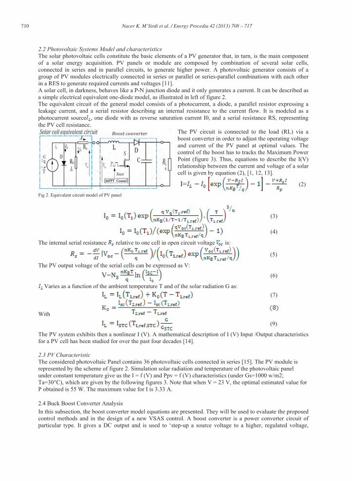
2.2 Photovoltaic Systems Model and characteristics The solar photovoltaic cells constitute the basic elements of a PV generator that, in turn, is the main component of a solar energy acquisition. PV panels or module are composed by combination of several solar cells, connected in series and in parallel circuits, to generate higher power. A photovoltaic generator consists of a group of PV modules electrically connected in series or parallel or series-parallel combinations with each other in a RES to generate required currents and voltages [11]. A solar cell, in darkness, behaves like a P-N junction diode and it only generates a current. It can be described as a simple electrical equivalent one-diode model, as illustrated in left of figure 2. The equivalent circuit of the general model consists of a photocurrent, a diode, a parallel resistor expressing a leakage current, and a serial resistor describing an internal resistance to the current flow. It is modeled as a photocurrent source , one diode with as reverse saturation current I0, and a serial resistance RS, representing the PV cell resistance.
The PV circuit is connected to the load (RL) via a boost converter in order to adjust the operating voltage and current of the PV panel at optimal values. The control of the boost has to tracks the Maximum Power Point (figure 3). Thus, equations to describe the I(V) relationship between the current and voltage of a solar cell is given by equation (2), [1, 12, 13].
I= (2) Fig 2. Equivalent circuit model of PV panel
(3)
(4)
The internal serial resistance relative to one cell in open circuit voltage is:
(5) The PV output voltage of the serial cells can be expressed as V:
V= (6) Varies as a function of the ambient temperature T and of the solar radiation G as:
(7)
With (9)
The PV system exhibits then a nonlinear I (V). A mathematical description of I (V) Input /Output characteristics for a PV cell has been studied for over the past four decades [14]. 2.3 PV Characteristic The considered photovoltaic Panel contains 36 photovoltaic cells connected in series [15]. The PV module is represented by the scheme of figure 2. Simulation solar radiation and temperature of the photovoltaic panel under constant temperature give us the I = f (V) and Ppv = f (V) characteristics (under Gs=1000 w/m2; Ta=30°C), which are given by the following figures 3. Note that when V = 23 V, the optimal estimated value for P obtained is 55 W. The maximum value for I is 3.33 A.
2.4 Buck Boost Converter Analysis In this subsection, the boost converter model equations are presented. They will be used to evaluate the proposed control methods and in the design of a new VSAS control. A boost converter is a power converter circuit of particular type. It gives a DC output and is used to ‘step-up a source voltage to a higher, regulated voltage,
Nacer K. M’Sirdi et al. / Energy Procedia 42 ( 2013 ) 708 – 717 711
allowing the power supply to different driving voltages. This DC-DC converter is used as a power interface circuit between the PV panel and the load or the battery. This circuit consists, in its simple way, of only a switch (typically a transistor), an inductor, and a capacitor connected as shown in figure 2. This converter connects/ disconnects conveniently the solar panel to its load based with a PWM (Pulse Width Modulation) signal. ((( ) gggg
(a) (b)
Fig 3 .I = f (Vpv) and Ppv = f (V): (a)I-V, (b)P-V characteristics curves of PV module
The buck converter is used due to two main advantages: (i)The required input current to the converter is small, (ii) The charge control operation remains uninterrupted even when the PV panel gives low output current at low level of isolation because the buck converter will boost the current up to the required level.
Fig4. Equivalent scheme model of PV panel The PV is connected to the load (RL) via a boost converter. To track the Maximum Power Point (MPPT) a DC-DC power electronic converter is inserted between the PV module and its load. To achieve the optimum matching and track the power Maximizing point, a good control of the DC-DC is necessary. The equivalent circuit-based model is mainly used for the MPPT conception. A simplified diagram of a boost converter is also illustrated in the right part of figure 2. As the temperature, insolation and load vary, an algorithm is used to ensure that the PV module always operates at its maximum power point. The boost converter contains passive components (inductor L, capacitor C and resistance RL) plus a diode, and an IGBT. If the state S is 0, the diode is on and the IGBT is off and vice versa if the state S is 1. The boost converter operation principle is the one of Variable Structure System (VSS);It can be represented for each switching mode (with a control variable noted u):
• u=1; the first mode is the ON mode during the period 0 < t < . The ON modes time it on and the inductor current is . The state equations can be represented as follows.
• u=0; the second mode is the OFF mode, during the period < t < , where Ts is the switching period.
The boost equation becomes: (11)
We can the obtain the following gathered model equations: (12)
u= (13)
Where D = is the duty cycle of the buck converter. The duty cycle varies between 0 and 1. The gain from the
boost converter is directly proportional to the duty cycle, the time the switch is ‘on’ each cycle . The switching frequency is An Ideal boost DC-DC converter works as an ideal DC transformer with an
electronically adjustable step-up ratio .
712 Nacer K. M’Sirdi et al. / Energy Procedia 42 ( 2013 ) 708 – 717
The design of a boost converter and its control for a PV system involves many factors depending on the solar irradiances and load variations. The Switching frequency of the Boost IGBT (changing s) is .
The reference voltage is generated from an MPPT (in classical case PI) controller to reach the maximum power. The selections of boost converter parameters (the inductor and the output capacitor) depend on the MPPT algorithm trigger time and the desired dynamic response.
3. RES Control system: the MPPT methods The aim of this part is the study of existing control systems to get the maximum power. As presented previously, an MPPT controller is used to increase the PV system efficiency. The principle is to calculate the optimal reference output voltage which ensures that the PV system operate at its MPP. These techniques are different from each other in many aspects, including simplicity, convergence speed, hardware implementation, sensors required, cost, range of effectiveness and need for parameterization (see [1] for a survey).
3.1 Previous work: The maximum performance of a photovoltaic system depend, of course, on good weather conditions, but needs also appropriate MPPT algorithm[16,17]. The majority of MPPT control strategies are based on the characteristics of PV panels, such as I-V or P-V plots, the duty cycle ratio control and sometimes using look-up tables[19]. There are several methods: voltage feedback method, perturbation and observation method, linear approximation method, incremental conductance method, hill climbing method, actual measurement method, fuzzy control method and so on[4-9]. In general, there exist four types of MPPT techniques: (i) The PV operation point Perturbation and Observation (PO) based algorithms in order to get the direction of tracking the MPP; (ii) The Hill-Climbing algorithm (HC) which makes a perturbation in duty cycle reaches the apex of the characteristics; (iii) The incremental conductance (InCond) algorithm which periodically checking the slope (conductance) of the P-V curve [11]. (iv) the constant voltage algorithm based on keeping constant the ratio between the PV voltage at the maximum power and the open circuit voltage (Voc) value; In this method the effect of solar irradiance variations is neglected [24] In [18,19], Ibrahim and Housing use a look-up table to track, when other author prefer the use of a dynamic MPP tracker to PV appliances [20]. A single-stage MPP controller using the slope the power versus voltage has been done in [21]. In [6] a DSP chips is used to implement the PO MPPT in order to get maximum power. They also try to improve the efficiency of the PO and HC methods [22]. In [7], the time response of PO [8,23] and HC methods [7,9,24,25] are compared for a grid connected system. The PO method can fail under rapidly changing atmospheric conditions. Several research activities have been carried out to improve the traditional Hill-climbing and P&O methods. Reference [26] proposes to use three measurement points to compute MPP. The method compares the obtained power measurement to the two proceeding points before choosing the perturbation sign. In [ 21] the authors propose a two stage algorithm that offers faster tracking in the first stage and more accurate tracking in the second stage. To prevent divergence from MPP, they use a modified adaptive algorithm. In [15] Tina et. al. proposed a mathematical model for the electrical-thermal coupling of a PV module with ambient temperature, wind speed, wind direction, relative humidity and electrical operating point (voltage and current values).An MPP tracking based on Dual boost converter is developed using fuzzy logic in [28]. Artificial neural networks (ANN), trained offline with a gradient descent algorithm using a back-propagation have been used by Kaiser et. al.[29] to generate (online) the reference voltage for MPPT control, in a solar electric vehicles. The MPPT algorithm controls the duty cycle of a boost converter to ensures the output voltage of a PV panel. The reported simulation and experimental results show a high efficiency. Another approach based on variable structure control is applied to a buck converter in [30]. In [4], the authors study and compare three maximum power point tracking (MPPT) algorithms, under different climate conditions, in a photovoltaic simulation: the algorithms of perturbation and observation (PO), incremental conductance (INC) and hill climbing (HC), respectively (see also [24,27]). They show that the photovoltaic simulation can track the maximum power accurately using the three MPPT algorithms.
Nacer K. M’Sirdi et al. / Energy Procedia 42 ( 2013 ) 708 – 717 713
3.2 Fixed Operating Point The problem is to find the voltage or the current at which the PV array delivers the maximum power under a given temperature T and irradiance G. Then to automatically put the PV in this condition. The first remark was that the MPP varies in a small region and that on the left part of the P-V characteristic, the slope P/V is roughly constant.
Fractional Open-Circuit Voltage . The first method uses the observation that, the ratio between array voltages at maximum power to its open circuit voltage
g is
nearly constant. . The factor . is not constant but, has been remarked to be between 0.71 and 0.78. Once the constant is known, can be computed. This method consists in measuring periodically and then fixing = . The implementation is simple and cheap, but the tracking efficiency is relatively low due to inaccurate values of the constant k1 in the computation of . Fractional Short-Circuit Current. This method is based on the remark that the current at maximum power point is approximately proportional to the short circuit current . of the PV array. . The factor is not constant but, has been remarked to be between 0.78 and 0.92. Once the constantt . is known can be computed. The accuracy of this method and its tracking efficiency depend on the accuracy of knowledge of
and the periodic measurement of short circuit currentttttt . Fig5. Flowchart of the PO method
3.3 Perturb and Observe Method The most commonly used MPPT algorithm is the Perturbation and Observation (PO) due to its easy implementation. It uses the P-V characteristics Ppv = f (V) of the PV module shown in figure 3 (b). Note that the point of maximum power P(n)=V(n)I(n) is obtained when the condition is accomplished, regardless of
the sun irradiance magnitude. We can be calculating the slope of the power versus the voltage using consecutive
outputs measurements (voltages and output). It can be expressed as follows,
• If the operating voltage of the PV array is perturbed in a
given direction and > 0, then the perturbation moves the array’s operating point toward the MPP. The PO algorithm would the continue to change the PV array voltage in the same direction
• If < 0 then the change in operating point moves the PV array away from the MPP, and the PO algorithm reverses the direction of the perturbation [31] Some limitations are encountered such as: oscillations around the MPP in steady state operation, slow response speed, and even tracking in wrong way when atmospheric condition instability [11,31,32].
The duty cycle of the Boost is changed and the process is repeated until the maximum power point has been reached. In actual experiments, the system oscillates around the MPP. To minimize the oscillations amplitude, we can reduce the perturbation step size. However, small step size slows down the convergence of the MPPT.
714 Nacer K. M’Sirdi et al. / Energy Procedia 42 ( 2013 ) 708 – 717
To solve this problem, we can use smaller perturbation size towards the MPPT 3.4 Incremental Conductance Methods The incremental conductance (IncCond) [31], method is based on the fact that the slope (or the PV conductance G= ) of the PV array, in the power curve is zero at the MPP and it is positive (constant) on the left of the MPP. The slope becomes negative on the right of the MPP. These relations can be rewritten in terms of the array current and voltage as:
+VVVVVVVVVVVVVV (15) to keep DP/DV = 0 we need:
G= (16) DP/DV = 0 at the MPP
• If G = (this means that ), the operating point is on the left side of the MPP, V has
to be raised. • If G = (dP/dV<0), the operating voltage is on the right
side of the MPP then V has to be reduced.
3.5 Hill Climbing Method In general the almost applications, use DC-DC converters and DC-AC inverters, as the power interface devices between PV modules and loads. The basic idea of the HC (Hill Climbing) method is the same as P&O method. It tests if P(n) is greater than P(n-1) or not, to reach MPP. The PO method uses instead a test on dP/dV to determine whether the maximum power point has been found or not. However, the HC method uses a test condition on P(n)-P(n-1) and uses the duty cycle (D) of these switching mode power interface devices as the decision action parameter for the maximum power point tracking. The figure7 shows a flow diagram of the hill climbing algorithm
The implementation of the proposed enhanced MPPT controller can be summarized as follows: 1. The reference voltage is set be equal to the double of the PV open circuit voltage. 2. Measurement of the of input signals (PV voltage, PV current and Load voltage). 3. Estimate the PV power at the sample time k:
4. Calculate the PV current and PV power increments as follows:
(17)
The reference voltage is calculated as below, where is the perturbation variation step. Note that produces exactly the same result as the classical PO algorithm with a much simpler
implementation. We propose, as a modified PO Algorithm which will be more robust, the reference voltage is given by
(18)
Nacer K. M’Sirdi et al. / Energy Procedia 42 ( 2013 ) 708 – 717 715
This method gives an enhanced variable step size algorithm. The step size is adjusted in proportionally to the power variation produced in the previous step. The step adjustment gain K is used for weighting this adjustment step. It may be useful for oscillation avoidance and noise sensitivity. 3.6.2 RUCA: Robust Unified Control Algorithm The desired objective to get is that the MPP reached when the maximum power is obtained , if current is maintained constant. Note also that in real weather condition the Operating Point do not moves on a unique (P-V) characteristic. If the irradiation or the temperature changes the MPP varies from one curve of the figure 3 to another one. For fast and very good converging algorithms, the Operating Point has the most part of his motion from one characteristic curve to another, near the optimum. Then as P(t) = V(t).I(t) = f (V, I, t), the power is function of the voltage, the current and time, then the required Maximum Power Point to Track is really defined by the following objective function: y yyyyyyyyy g j
Let us consider the control in case of discrete time, like do all the above presented algorithms, with the previously defined variables (see equation (17)) the fetched MPPT may be defined by P(k) = 0, then as can be approximated by The objective function that we propose becomes then:
(20) In control point of view, the previously presented MPPT controllers using only one control variable or and impose the second to zero. The control variable is either, in the first case, (k) = V (k), which means that the voltage perturbed and the current is fixed (k) = I (k) = 0, or in the second case, the control variable is (k) =
I (k), the current is perturbed and the voltage is fixed (k) = V (k) = 0. For the proposed RUCA algorithm, both controls can be used if we look for adjusting both variables (V and I), either at each control step or alternatively. It can be noticed that the previous algorithms can be considered as particular cases of this one, when simplifying the proposed control method.3.6.3 RSMCA: Robust Sliding Mode Control Algorithm Let us write it equivalently the MPP reaching condition P (t). = 0 and note that the maximum power is always P (t) everywhere and at any time. Let us then consider the Lyapunov like function W (t) = ( which is stricly positive everywhere except at the MPP where it goes to zero. Lyapunov based control design is well known to give robust algorithms. The derivative of the proposed Lyapunov function W (t) = ( – > 0, is = -P(t). = -P(t). - P(t)V
. It can be made negative by choosing the appropriate control laws (k) = V (k) and (k) = I(k) to get a decreasing Lyapunov function. Note that again this can be reached by choosing the sign of (k) = V (k), or the sign of (k) = I(k), or both such as to get = = -( I + V < 0 or more simply, in discrete time
W = - (I V + V I) < 0. Another time this uses two control inputs which can be done either simultaneously or alternatively or one of them can be frozen depending on the needed voltage or current. Choosing (k) = V (k) = K. P(k):sign( V(k)) and (k) = I(k) = 0 like in the previously proposed MEPO control algorithm give us W = -K. . P(k).sign( V(k)) I(k) + V(k) I(k). Knowing that we impose I(k) = 0 and that P(k) = (I(k) V(k) + V(k) I(k)), we get W = -K. . P(k).sign( V(k)) I(k) If the gain parameters K and are all positive constants, we then get a negative derivative
W = -K. . (k) V(k).sign( V(k)) < 0 (21) This proves, theoretically the convergence of the MEPO algorithm.
= - (I + V < 0 (22) Recall the system equations can be used also to define classical Sliding Mode based algorithms by means of choosing a commutation surface. The best choice seems to be given by the proposed criteria in equations ([19] and[20]). This will be emphasized in our next work.
The studied and proposed algorithm are tested in simulation and compared with the use of weather measured data (see figure 1 b and c). The PV systems is made of 5 panel composed of 36 series connected cells
The Fig. 8 (a) shows a comparison of the output powers for the PV system with three different MPPT algorithms under the conditions of 1000W/ and 2,25°C. It can be observed that, despite the control gain needs to be
716 Nacer K. M’Sirdi et al. / Energy Procedia 42 ( 2013 ) 708 – 717
adjusted; the output powers with MEPO and RUCA technique that we propose are obviously greater than those using classical PO and Inc MPPT algorithms.
Fig8 PV panel power with 3 algorithm In-Cond, PO, and MEPO, (b) PV panel power with Three algorithms In-Cond, PO, and MEPO
Moreover, to evaluate the performance the proposed MPPTs, the PV system is exposed to solar irradiation with random changes that correspond to normal solar changes; Let us consider an irradiation change according to the diagrams shown in Fig. 9 (a). The corresponding results are presented in figure 9 (b). The third test is considered for all a day long. The Figure 8 (b) shows the Powers generated for this day by the three methods. This shows the effectiveness of the proposed algorithms.
(a) (b) Fig9. Power generated by the tree methods of MPPT a) Simulation of irradiation change and b) MPP Tracking under irradiation change Conclusion In this paper, the problem Renewable Energy Systems has been considered for analysis and simulation. The rationale behind of the algorithms used for MPP Tracking has been clarified and analyzed in a unified framework. The previous papers consider only the steady state MPP definition and do not involve key performance index definition. This analysis allow us to understand how are used these algorithms and how to get good results by appropriate tuning of them. The most important point is not the competitively between the algorithms but the well understanding to get parameters well tuned and adapted according a valuable key performance criterion. The problem considered is a Variable Structure System and then has to be treated in consequence. The PO algorithm has fast dynamic response and shows a well-regulated PV output voltage, better than HC algorithm. Since the InCond algorithm is more complex, the time response of InCond is a little longer. But as shown in our analysis they consider an MPP defined using the steady state (IV or PV) characteristics. The proposed MEPO is based on the VSAS and uses a target performance criterion (equation 19). It enhances widely the efficacy of the PO and is generalized by the RUCA. This is clearer and emphasized by the analysis of the RSMCA algorithm Robust Sliding Mode Control Algorithm. The experimental validation for different kinds of RES is in good progress and this analysis show us how to get minimal cost for real implementation of the algorithms avoiding heavy structures. The paper proposes simple to implement MPPT methods that require only measurements of PV voltage and current. The classical methods are first recalled and considered then a Modified Enhanced Perturb and Observe
Nacer K. M’Sirdi et al. / Energy Procedia 42 ( 2013 ) 708 – 717 717
method (MEPO) is first considered. After that a RUCA (Robust Unified Control Algorithm) method has been detailed. The main interest was again the understanding of the system dynamics and need for adjustment. The advantages of these methods are their simple structure, easy implementation and less required parameters. The results show that the proposed method guarantees good tracking efficiency under different operating conditions and relatively high convergence speed. References [1] J. Schaefer, Review of Photovoltaic Power Plant Performance and Economics, IEEE Trans. Energy Conversion, Vol. EC-5, pp 232-238, June 1990. [2] D. Connolly, H. Lund, B.V. Mathiesen, M. Leahy. A review of computer tools for analyzing the integration of renewable energy into various energy systems, Applied Energy 87, 1059–1082, 2010. [3] F. Sheri_, D. Turcotte and M. Ross, “PV toolbox: a comprehensive set of PV system components for the Matlab/Simulink environment ”SESCI 2003 conference Queen’s University Kingston, Ontario, Canada August 18 to 20, 2003. [4] Ting-Chung Yu, Yi-Ting Shen, “Analysis and Simulation of Maximum power point tracking for photovoltaic systems,” Proceedings of the30th ROC Symposium on Electrical Power Engineering, Taoyuan, Taiwan, pp. 92-96, Nov. 28-29, 2009. [5] C.A.P. Tavares, K. T. F. Leite, W. I. Suemitsu, M. D. Bellar, “Performance evaluation of photovoltaic solar system with different MPPT methods,” Industrial Electronics, 2009. IECON’ 09. 35th Annual Conference of IEEE, pp.719-724, 3-5 Nov. 2009. [6] C. Hua, J. Lin, C. Shen, “Implementation of DSP-controlled photovoltaic system with peak power tracking, ” IEEE Trans. On Industrial Electronics, Vol. 45, No. 1, 1998, pp. 99-107 [7] Fangrui Liu, Yong Kang, Yu Zhang, Shanxu Duan, “Comparison of P&O and hill climbing MPPT methods for grid-connected PV converter,” 3rd IEEE Conference on Industrial Electronics and Applications, 2008 (ICIEA 2008), pp.804-807, 3-5 June 2008. [8] Chih-Chiang Hua, Jong-Rong Lin, “Fully digital control of distributed photovoltaic power systems,” Proceedings of IEEE International Symposium on Industrial Electronics (ISIE 2001), vol. 1, pp. 1-6, June 2001. [9] Weidong Xiao, A modified adaptive hill climbing maximum power point tracking control method for photovoltaic power system, Master Thesis, The University of Brtish Columbia, July 2003. [10] A.W.M. (Jos) van Schijndel and M.H. (Martin) de Wit, Advanced simulation of building system and control with Simulink , Eighth International IBPSA Confer ence Eindhoven, Netherlands, August 11- 14, 2003 [11] Liu X., Lopes L.A.C.: “An improved perturbation and observation maximum power point tracking algorithm for PV arrays” Power Electronics Specialists Conference, 2004. PESC 04. 2004 IEEE 35th Annual Volume 3, pp. 2005 – 2010, 20-25 June 2004 [12] Y.-T. Hsiao and C.-H. Chen, Maximum power tracking for photovoltaic power system, in Conf. Record of the 37th IAS Annual Meeting Ind. Applicat. Conf, pp. 1035-1040, 2002. [13] G. Walker, Evaluating MPPT converter topologies using a MATLAB PV model, Journal of Electrical & Electronics Engineering, Australia, IEAust, vol.21, No. 1, pp.49-56, 2001. [14] MATLAB/Simulink “Creating Graphical User Interfaces” Version 7.9 [Online]. Available : http://www.mathworks.com/access/ helpdesk/ help/ techdoc / creating guis/ bqz79mu.html. [15] G.M. Tina and S. Scrofani, Electrical and Thermal Model for PV Module Temperature Evaluation, IEEE Electrotechnical Conference, May 2008, pp. 585-590. [16] N. Mutoh, M. Ohno, T. Inoue, “A method for MPPT control while searching for parameters corresponding to weather conditions for PV generation systems,” IEEE Transactions on Industrial Electronics, vol.53, no.4, pp.1055-1065, June 2006. [17] NianChun Wang, Zuo Sun, K. Yukita, Y. Goto, K. Ichiyanagi, “Research of PV model and MPPT methods in Matlab,” Asia-Pacific Power and Energy Engineering Conference (APPEEC 2010), pp.1-4, 28-31 March 2010. [18] Ibrahim, H.E.S. A. and Houssiny, FF, Microcomputer Controlled Buck Regulator for Maximum Power Point Tracker for DC Pumping System Operates from Photovoltaic System, Proc of IEEE International Fuzzy Systems Conference, August 22-25, V1, pp406-411 (1999). [19] K. Amei, Y. Takayasu, T. Ohji, and M. Sakui, A Maximum Power Control ofWind Generator System Using a Permanent Magnet Synchronous Generator and a Boost Chopper Circuit, IEEE Power Conversion Conference, vol. 3, 2002, pp. 1447- 1452. [20] Midya, P., Kerin, P. T., Turnbull, R. J., Reppa, R. And Kimball, J., “Dynamic Maximum Power Point Tracker for Photovoltaic Applications,” Proceedings of the IEEE Power Electronics Specialists Conference, PESC, Vol. 2, pp. 1710-1716 (1996). [21] Kuo, Y. C., Liang, T. J. and Chen, F. C., “Novel Maximum-Power-Point-Tracking Controller for Photovoltaic Energy Conversion System”, IEEE Transactions on Industrial Electronics, Vol. 48, pp. 594- 601 (2001). [22] Koutroulis, E. And Voulgaris N. C., “Development of a Microcontroller-based photovoltaic Maximum power point tracking control system”, IEEE Transactions on Power Electronic, Vol. 16, No. 1, January 2001. [23] Jia-Chen Zhuang, Photovoltaic Engineering-Solar Cells, Chuan Hwa Book CO., LTD, Taipei, 1997. [24] D. P. Hohm, M. E. Ropp, “Comparative study of maximum power point tracking algorithms,” Progress in Photovoltaics: Research and Applications, vol. 11, no. 1, pp. 47–62, January 2003. [25] T. Esram, P. L. Chapman, “Comparison of Photovoltaic Array Maximum Power Point Tracking Techniques,” IEEE Transactions on Energy Conversion, vol. 22, no. 2, June 2007. [26] W. Xiao and W. G. Dunford,“A modified adaptive hill climbing MPPT method for photovoltaic power systems,” 35th. Annual IEEE Power Electron. Specialists Conf. , pp. 1957-1963, 2004 [27] D.P. Hohm, and M.E. Ropp. Comparative study of maximum power point tracking algorithms using an experimental, programmable, maximum power point tracking test bed, Photovoltaic Specialists Conference, Sept. 2000, pp. 1699-1702. [28] Veerachary, M., Senjyu, T., and Uezato, K. “Feedforward maximum power point tracking of PV systems using fuzzy controller”. IEEE Transactions on Aerospace and Electronic Systems,Vol. 38, 3 (July 2002), 969-981. [29] M. Kaiser, S. Aditya, and R. Mazumder, Performance Evaluation Of A Maximum Power Point Tracker (Mppt) For Solar Electric Vehicle Using Artificial Neural Network, Da_odil International University Journal Of Science And Technology, vol. 1, issue 1, July 2006. [30] Miao, Z., W. Jie, et al., “The application of slide technology in PV maximum power point tracking system”, Fifth World Congress on Intelligent Control and Automation, WCICA, 2004. [31] Femia N., Petrone G., Spagnuolo G., Vitelli M, Optimizing duty-cycle perturbation of P&O MPPT technique. Power Electronics Specialists Conference, 2004. PESC 04. 2004 IEEE 35th Annual Volume 3, pp.1939 - 1944, 20-25 June 2004. [32] T.-Y. Kim, H.-G. Ahn, S. K. Park, and Y.-K. Lee, A novel maximum power point tracking control for photovoltaic power system under rapidly changing solar radiation, in IEEE International Symp. On Ind. Electron, pp. 1011-1014, 2001.