A novel approach to disturbance rejection in idle speedcontrol towards reduced idle fuel consumption
C Manzie* and H C WatsonDepartment of Manufacturing and Mechanical Engineering, The University of Melbourne, Australia
Abstract: Idle speed control remains one of the most challenging problems in the automotive control�eld owing to its multiple-input, multiple-output structure and the step nature of the disturbancesapplied. In this paper a simulation model is described for a 4.0 l production engine at idle whichincludes the standard bypass air valve and spark advance dynamics, as well as the e�ects of operatingpoint on cycle-by-cycle combustion-generated torque variations. A model predictive control schemeis then developed for the idle bypass valve and spark advance. The idle speed control algorithm isbased on rejecting the torque disturbance using model predictive control for the bypass valve dutycycle while minimizing the transient e�ects of the disturbance by adjusting the spark advance.Simulation results are presented to demonstrate the e�ects of di�erent elements of the controller suchas levels of spark o�set from minimum spark advance for best torque at idle and feedforward loadpreviews. Compensation of the e�ects of cyclic variation in combustion torque is also implementedin the controller and its bene�ts are discussed.
a, b parameters of AR combustion modelAFI( ) AFR in�uence functionAFR air–fuel ratioBPAV bypass air valveBTDC before top dead centreC number of cylindersJ engine inertia (kg m2)k current eventkE load eventL
p load preview length (events)mb
ai mass of air �ow into manifold (g)mb ao mass of air �ow out of manifold (g)Ma molar mass of airMAP manifold absolute pressureMBT minimum spark advance for best torqueMPC model predictive controlN engine speed (r/min)Pm intake manifold pressure (kPa)SI( ) spark in�uence functionTa ancillary load torque (N m)
The MS was received on 28 June 2002 and was accepted after revisionfor publication on 3 April 2003.* Corresponding author: Department of Mechanical and ManufacturingEngineering, The University of Melbourne, Parkville, Victoria 3010,Australia.
Tc , Tc actual and predicted combustion torques(N m)
Td , Tf Disturbance and engine friction torques(N m)
Tl expected ancillary load torque (N m)
Tman intake manifold temperature (K)TMBT combustion torque produced at MBT
(N m)Tprev magnitude of load preview torque (N m)TDC top dead centreuBP bypass valve duty cycle
Ve engine displacement (m3)Vm intake manifold volume (m3)
c weight on predicted errorgvol volumetric e�ciencyh spark advance (° BTDC)h
MBT spark advance for MBT (° BTDC)l weight on controller changesw standard deviation of combustion (N m)
1 INTRODUCTION
Idle speed control remains a challenging problem in theautomotive control �eld, and many varied solutions havebeen proposed to deal with it. Some recent examples
at The University of Melbourne Libraries on January 7, 2014pid.sagepub.comDownloaded from
include multivariable PI tuning [1 ], sliding mode basedcontrol [2 ], L1 optimal control [3 ] and neural networkbased control [4 ]. Within the many suggested solutions,the goal of idle speed control remains the same—toenable the engine with closed throttle to run at lowenough engine speed to minimize fuel consumption butnot so low that the engine’s noise, vibration and harsh-ness (NVH) quality is compromised. The worst-casescenario is that the engine speed falls low enough tocause engine stall (i.e. it stops). The primary di�cultywith the control problem is that the engine at idle issubject to step disturbances from accessory loads suchas the air conditioner being switched on or engagementof the automatic transmission. The torque disturbanceon application of these types of loads serves to decreasethe engine speed and must be rejected.
In the modern automotive engine there are three controlvariables that may be used to increase combustion gener-ated torque and hence reject torque disturbances—air–fuel ratio (AFR) of the charge mixture, manifold absolutepressure (MAP) and spark advance. To achieve highexhaust catalyst e�ciency, emission regulations require theAFR to be kept at or close to stoichiometry, which maybe achieved using control schemes such as those docu-mented in references [5] and [6 ]. Thus AFR is generallynot considered in idle speed control schemes except as alast resort, leaving only the other two control parameters.
The manifold pressure can be adjusted by altering theair �ow from the environment to the intake manifoldthrough adjustment of the nearly closed throttle or aroundthe closed throttle. The air �ow around the throttle maybe maintained by a bypass air valve (BPAV) or throughthe use of electronic throttle control as is becoming moreprevalent with the advent of drive-by-wire productionautomobiles. In this paper we have assumed the use of aBPAV, although the results are equally applicable to elec-tronic throttle systems, only the relevant transfer functionwill be changed. The duty cycle of the control signal forthe BPAV dictates air �ow into the cylinder and thus con-trols the manifold pressure. This has a very large in�uenceon the amount of torque produced but has the disadvan-tage of requiring enough air �ow to change the density inboth the manifold and the engine. There is also one enginerevolution delay between �lling the cylinder and powerdelivery. Clearly this delay is inversely proportional toengine speed.
Spark advance o�ers a much faster control response.There is a spark advance for every operating conditionwhich results in maximum torque production; however,the peak of this curve is quite �at and so the minimumadvance for best torque (MBT) is often used as an indi-cator of best torque production, and the spark is notadvanced past the MBT as combustion becomes rapidlymore unstable. The spark is retarded from the MBT andthe air �ow increased at idle to give a fast source ofadditional torque. The response delay is reduced for eachspark; for example, in a six-cylinder engine the spark delay
is about one-sixth of the air �ow response time. However,there is a limited amount of ‘fast’ torque available as dic-tated by the degree of spark o�set from the MBT.Furthermore, as the spark is retarded further from theMBT the resulting drop in combustion torque must bemade up by increasing the air and fuel charge into theengine, and hence fuel consumption increases with anincrease in spark o�set from the MBT.
Complicating the idle speed control problem, particu-larly at low engine speeds, is the variability in producedtorque at a given operating point on a cycle-by-cycle basis.That is, even given identical engine operating conditionsthe amount of torque generated by combustion is not con-stant but �uctuates signi�cantly. The relative magnitudeof these �uctuations is known to increase with decreasingMAP (and therefore decreasing engine speed given thesame external load conditions) and increasing spark retardfrom the MBT, making it more di�cult to reduce the idlespeed without increasing speed �uctuations.
In most current production automobiles, the multi-variable nature of the problem is handled by using PIcontrol on the BPAV and proportional control on thespark advance [7 ]. While these schemes do work, under-standably they tend to be far from optimal and requireidle speeds of around 800 r/min to ensure smooth oper-ation, and this has spawned the proposal of moreadvanced algorithms for the problem. Unfortunately thelack of suitable multiple-input, multiple-output controltools has meant that most of the advanced idle speed con-trol schemes proposed in the literature use only the bypassair valve as the control variable, e.g. references [3 ] and [8].One exception is reference [9 ], where a �xed H-in�nitycontrol, applied to a linearized version of the enginescheme, used a load preview to increase the torque reservetemporarily to cope better with load applications.
The purpose of this paper is to present an algorithm fora two-stage control of the spark and BPAV. In the �rststage a model predictive control (MPC) method with noweighting on changes to the spark advance is used to com-pensate for immediate and predicted torque disturbances,while in the second stage higher weighting is used for thecontrol changes in the BPAV to set the manifold pressuresmoothly to a desired steady state level to compensatecompletely for the torque disturbance. It is noted that,unlike in reference [9 ], linearization of the engine transferfunctions is not required.
This paper is organized as follows. In Section 2 anevent-based model for the engine of interest at idle isdetailed. In Section 3 the model is used in the derivationof the control law, and in Section 4 simulation resultsfor a widely varying range of control options are pro-duced and the most suitable controller structure is dis-cussed. Conclusions about the algorithm’s ability toreject disturbances and to compensate signi�cantly forcombustion variability are summarized in Section 5,while the test engine used throughout the paper isdescribed in the Appendix.
at The University of Melbourne Libraries on January 7, 2014pid.sagepub.comDownloaded from
In models for idle speed engine control an event-basedmodel is typically used, with each combustion strokerepresenting a single event. Hence, in a six-cylinder, four-stroke engine there are six events for every two enginerevolutions.
Event-based models are used because most delays arenot based on time but on engine cycle, and the air �owequations are linearly dependent on engine speed, whichis proportional to combustion event generation. It is alsoan intuitive approach for idle speed modelling, as torqueproduction (and hence variation in the engine speed)occurs on spark ignition.
The assumption that an accurate AFR control strat-egy such as those described in references [6 ] and [10] isimplemented and maintains a constant AFR in the idleoperating region allows the process of fuel pooling inthe intake manifold to be ignored, unlike a traditionalmean-value engine model, e.g. see reference [11 ].Furthermore, at idle and low MAP the in�uence of fuelpooling will be much smaller or non-existent because ofthe low pressure compared with the fuel vapour pressure;hence the assumption of ideal AFR control may berelaxed slightly without necessitating the modelling offuel pooling for idle speed applications. Thus only twostates are required to describe the event-based idle speedmodel, these being the manifold pressure and the enginespeed. The �lling and emptying of the intake mani-fold and the torque production processes respectivelydetermine each of these states.
Figure 1 depicts in block diagram form the event-based model that is used throughout this work. Theindividual component blocks will be discussed in thefollowing sections.
2.1 Modelling �lling and emptying of the intakemanifold
The manifold pressure state equation is derived fromconservation of mass considerations in the intake mani-fold under the assumption of constant temperature oper-ation. In the event domain for the engine of interest(described in the Appendix) this can be derived from the
Fig. 1 Event-based model of the engine during idle operation
conservation of mass in the intake manifold as follows:
Pm(k+1)�Pm(k)=RTm
MaVm(mb ai�mb ao)
=1.6933(mb ai�mb ao) (1)
At idle, the mass air �ow into the manifold, mb ai(k), isthe air that is bypassed around the closed throttle andis dependent on the driver circuit for the BPAV. Becausechoked �ow conditions exist at idle the air �ow is inde-pendent of the intake manifold pressure and enginespeed. The transfer characteristic is usually stated as afunction of the duty cycle of the (�xed frequency) signalsent to the valve, although it is more correct to state itin terms of current �ow through the solenoid. The trans-fer function of the valve was obtained by driving thesolenoid with a modi�ed injector driver circuit based onthe LM1949 integrated circuit, with one side of the solen-oid connected to the battery voltage and the other vary-ing from 0 to battery voltage at the given duty cycleusing a 160 Hz frequency. Figure 2 illustrates the massair �ow into the engine as a function of BPAV duty cyclefor the driver circuit used here.
A linear trendline was �tted to the data, and the equa-tion of this trendline, where u
BP is the BPAV duty cycle,was calculated to be
mb ai=0.2102uBP�2.2928 (g/s)
= [4.204uBP (k)�45.856]/N (g/event) (2)
The mass air �ow out of the manifold, mb ao(k), isdescribed by the well-known speed density relation inthe time domain.
mb ao=Ve
120VmgvolPmN (g/s) (3)
Previous research has shown that the volumetrice�ciency–manifold pressure product (gvolPm) has alinear relation in P
m for a given engine [12]. This wascon�rmed from steady state engine data for the engineof interest and subsequently the following relation was
Fig. 2 Mass air �ow into engine as a function of BPAV dutycycle. Horizontal bars represent measurement error.The trendline �t has an R2 value of 0.99
at The University of Melbourne Libraries on January 7, 2014pid.sagepub.comDownloaded from
used for mass air �ow into the engine at a �xed operatingtemperature:
mb ao(k)=0.0387[9.35×10Õ3Pm(k)�0.134]N (g/s)
=0.774[9.35×10Õ3Pm(k)�0.134] (g/event)(4)
2.2 Modelling the combustion process
By de�nition, the maximum torque produced is at theMBT; however, the operating point, the AFR and thespark timing all in�uence the fraction of maximumtorque produced by the combustion. The following twoequations from reference [13] model the torque pro-duced at MBT, TMBT , and the spark advance for MBT,h
MBT , for the test engine:
TMBT (k)=4.01Pm(k�1)
+0.041N(k)�126.4 (N m) (5)
hMBT (k)=27.03�0.322Pm(k�1)
+0.009 55N(k) (° BTDC) (6)
(BTDC, before top dead centre). The fraction of maxi-mum torque generated by combustion is in�uenced byboth the AFR and the spark retard from the MBT.These individual fractions are calculated independentlyas the AFR in�uence AFI(·) and spark in�uence func-tion SI [h (k)] respectively. Therefore the torque gener-ated by the combustion may be represented by thefollowing equation taken from reference [11]:
Tc(
k)=TMBT [Pm(k�1), N(k)]SI [h (k)]AFI Cmb ao(k�1)
mbfo(k�1)D
(7)
As stoichiometric AFRs are assumed in this paper, theAFR in�uence function remains constant. In reference[11] the spark in�uence function was modelled for sparkretards from the MBT as the following sinusoidalexpression:
SI(h )=cos2.875(hMBT�h ) (8)
Recently [13], it was found that the above equationholds at high manifold pressures but in low manifoldpressure regions such as at idle the combustion varia-bility increases with spark retard from the MBT as wellas manifold pressure, and these factors combine toproduce the following relations to describe the sparkin�uence function:
SI(h )= [cos(hMBT�h )]f(Pm) (9)
f (PM)=2.5+103 exp(�0.15Pm ) (10)
This de�nes the expected torque produced by combus-tion at a given engine operating point. It has been arguedin reference [13] that the exponential dependence inequation (10) is to be expected.
However, torque production in a spark ignition engine
is not identical at each event at a given operating con-dition. When residual gas composition and temperaturee�ects are substantial, as at idle, for a given cylinder thevariations from the expected (or mean) torque dependon the past deviations. Previously this has been proposedas the residual gas dynamic e�ect, and it is analysed indetail in reference [9 ]. It was found in reference [13] thatthe following model of cyclic variations in indicated(combustion) torque was applicable for a C-cylinderengine in the idle operating range:
CTc(
Pkm , hk+C)�Tc(
Pkm , h k+C)
Tc(PkÕCm , h k)�Tc(PkÕCm , h k) D=Ca b
1 0D C Tc(PkÕCm , h k)�Tc(PkÕCm , h k)
Tc(
PkÕ2Cm , hkÕC)�Tc(
PkÕ2Cm , h kÕC)D+Cs
w0 D w
k(11)
The stochastic nature of combustion is indicated by thenoise variable w
k~N(0, 1), while Tc refers to the mean
combustion torque at the given operating point and Tc
is the actual torque. Note that the assumption that allcylinders operate independently means that C duplicatesof equation (11) must be maintained in the enginemodel. The parameters of the model were found exper-imentally for the engine of interest in the idle operatingregion to be a=�0.975 and b=�0.55. The standarddeviation of combustion variance was found in refer-ence [13] to be dependent on both intake manifold press-ure and spark retard from the MBT according to thefollowing equation:
sw=2.4+0.22(hMBT�h )+150 exp(�0.11Pm)(12)
2.3 Modelling the engine speed state equation
At idle, the load or disturbance torque applied to theengine, Td, is made up of the engine friction torque(which is linearly related to engine speed) and allother accessory torque applications. The engine speedstate equation for an engine with inertia J followsfrom Newtonian mechanics: Nb =(1/J ) (Tc
�Td). In the
event domain this can be shown to be approximatelyequivalent to the discrete equation
N(k+1)=N(k)+900
JN(k)[Tc (k)�Td(k)] (r/min)
(13)
For the engine of interest the inertia is known to be J=0.1454 kg m2. The total disturbance torque is made upof the engine friction torque, Tf , and any ancillary torquedisturbances, Ta , from sources such as power steering atfull lock or air conditioner engagement:
Td=T
f+T
a (14) at The University of Melbourne Libraries on January 7, 2014pid.sagepub.comDownloaded from
The friction torque was estimated from steady statemeasurements to be
Tf=0.0203N+4.75 (N m) (15)
The engine model is now complete and can be used asa realistic simulation environment in which to test idlespeed control strategies.
3 IDLE SPEED CONTROL SCHEME
3.1 Model predictive control
Consider a discrete time system with state equation a�nein the input and non-linear in the state, i.e.
x(k+1)=gk
¢u(k)+ f [x(k)] (16)
Now de�ne the following N-vectors and N×N matrices:
X= [x(k+1) .. . x(k+N )]T
¢U=[¢u(k) .. . ¢u(k+N�1)]T
F= [ f (x(k)) . .. f (x(k+N�1))]T
G=Cgk
0
P0 g
k+NÕ1D
(17)
A receding horizon of this system of length N time stepscan be de�ned in vector form as
X=G ¢U+ F (18)
A standard result in model predictive control for thesetypes of systems to follow some desired state trajectoryX
des= [xdes(
k+1) . .. xdes(
k+N )]T over the next Nsample points is given by minimizing a quadratic costfunction with respect to the control trajectory. Weightingis given in the cost function to both the change in controlmagnitude, ¢U, and the di�erence between the predictedand desired states, X�X
des, using two N×N matricesde�ned as
¡=Cc1 0
P0 c
ND and ¤=Cl
1 0
P0 l
ND
The result of the cost function minimization is given inthe following equation:
¢U=(¤+GT¡G )Õ1GT¡ [ Xdes� F(x)] (19)
The �rst element in the control trajectory ¢U is used asthe control signal and the vector is recalculated at eachcontrol step. One of the often-mentioned limitations ofmodel predictive control for real-time applications is thematrix inversion required in equation (19). However,the control is simpli�ed substantially in the case wherethe same weights are used for each of the N steps in the
of linear dependence of the state on the control does notchange (i.e. g
j=g for jµ[k, k+N�1]). In this situation
much of the computation can be completed o� line, sig-ni�cantly lightening the computational burden of thematrix inversion.
Clearly increasing l reduces the rate at which the con-trol can react to sudden changes and so acts as a lowpass �lter type constant. As a further point, the possi-bility exists that the optimal control signal, u(k), fallsoutside the boundary of physically realizable signals.Theorem 2 of reference [6 ] proves that the use of a satu-ration function of the following form optimally solvesthe constrained problem:
u(k)= Gumax, u(k)"umaxu(k), u(k)µ(umin , umax)
umin, u(k)åumin
(20)
3.2 Application to idle speed control
The base algorithm used in this paper focuses on ident-ifying the torque disturbance on the basis of engine speedmeasurements. There are two parts to the algorithm: thespark advance treats the disturbances immediately withone-step-ahead control, and a steady state solution basednominally requiring no change to the spark advancewhich centres around adjusting the manifold pressurewith model predictive control of the bypass valve. Thetwo steps are now detailed as follows.
The spark bypass is to be used to treat deviationsimmediately, and so no weighting should be applied tothe control or change in control signal. In e�ect the situ-ation is a one-step-ahead control solution as the controlis selected so that the next output is equal to the desiredoutput. The algorithm is illustrated in Fig. 3 and is basedon using the spark advance to equal the total disturbance
Fig. 3 Determination of desired retard from the MBT at The University of Melbourne Libraries on January 7, 2014pid.sagepub.comDownloaded from
torque plus enough additional torque to return the speedto its desired set point. This is achieved by inverting thespark in�uence function, equation (9), to give thedesired spark retard from the MBT. A saturation func-tion is applied to this value to prevent the spark beingadvanced past the MBT and also to prevent retardslarger than 40° from the MBT. This maximum retardwas chosen somewhat arbitrarily to maintain the sparkretard from the MBT in a range where combustion isnot too unstable but could easily be modi�ed to beadapted via a learning algorithm.
The physical disturbance torque can be estimatedfrom equation (13) using the previous torque producedby combustion (this can either be measured or be esti-mated from the manifold pressure and spark advance)and measurements of the engine speed, while the pre-dicted disturbance torque is a purely synthetic variablethat can be used to implement load previews or to com-pensate for predicted torque variations on a cycle-by-cycle basis.
Step 2: Steady state disturbance compensation—controlof the BPAV
Substitution of equations (2) and (4) into equation (1)allows a state equation for manifold pressure to beobtained which is in the form given in equation (16)under the assumption that the engine speed is approxi-mately constant between sampling events. This is demon-strated in the following equation, where k
1 , k2 and k
3represent constants with respect to the state (manifoldpressure) and control (BPAV duty cycle) signals.
Pm(k+1)= f [uBP(k), Pm(k)]
=k1uBP (k)+k
2P
m(k)+k3 (21)
The method for determining the BPAV duty cycle to beused is illustrated in Fig. 4 and starts with the estimationof the current disturbance torque. The required torquereserve is then added to this value to calculate the torquethat is required for the engine to run in steady state atthe desired speed and torque reserve. Feedback betweenthe engine speed and manifold pressure is also included
in a integral error loop to give the required torque forthe current operating point. This is necessary at lowtorque reserves, otherwise the spark may be advancedto the MBT but not enough torque is produced toincrease the speed to the desired level. The proportionalloop also helps to compensate for modelling errors inthe MBT surfaces and prevents deviations too far fromthe desired speed. Once the required MBT torque isestablished, equation (5) can be inverted to give themanifold pressure needed to generate this amount oftorque at MBT. This is then chosen as the desired outputof the system, equation (21), and the MPC controller isused to select the BPAV duty cycle. A saturation functionis used to restrict the duty cycle to a physically allowablerange, i.e. the minimum duty cycle required to unseatthe valve and the maximum duty cycle at which the valvewill operate (in this paper these duty cycles are taken tobe 0.15 and 0.85 respectively). A model predictive con-troller was chosen because it does not necessitate lin-earization of the engine models, and the robustnessproperties of model predictive controllers are well knownand established, e.g. references [14] to [16 ].
Because the algorithm centres on torque disturbanceestimation, additional predictive elements can be easilyincorporated into the algorithm. Delaying the appli-cation of an external load, or knowledge of its imminentapplication while the torque disturbance estimate isincreased, incorporates a feedforward aspect to thescheme. Similarly, compensation for e�ects such as pre-dicted cyclic variability of combustion can be achievedby adjusting the disturbance torque prior to setting thespark advance.
4 SIMULATION RESULTS
All the simulation results displayed in this paper focuson the application and removal of a step load of magni-tude 10 N m, as this models switching on and o� an airconditioner reasonably accurately and is a standard testin the idle speed control literature. Initially the e�ect ofcyclic variations in combustion torque will be neglected,i.e. the parameters a, b and s
w in equation (11) wereset to 0, so that the disturbance rejection performanceof the algorithm and the control signals could beinvestigated without the e�ects of noise.
4.1 E�ect of torque reserve on disturbance rejectionfollowing a load event
In the �rst simulation, the e�ect of di�erent levels oftorque reserve was investigated. Figure 5 demonstratesthe trajectory of engine speed using torque reserves of2, 6 and 10 N m. The maximum deviations below thespeci�ed speed set point of 600 r/min are 175.0, 92.9 and45.7 r/min for the torque reserves of 2, 6 and 10 N m
at The University of Melbourne Libraries on January 7, 2014pid.sagepub.comDownloaded from
Fig. 5 Engine speed on engagement (event 50) and removal(event 150) of 10 N m load using di�erent torquereserves
respectively. As expected, with higher torque reservecomes a greater ability of the algorithm to reject thedisturbance and less deviation from the set point isobserved.
The control signals for each of the torque reservessimulated are seen in Fig. 6. Naturally, the lower thetorque reserve, the more time the spark advance spendsin the saturated region on application of the load. Alsonote that there are small oscillations in both control sig-nals before they reach steady state. This occurs partlybecause of the feedback of engine speed into the desiredmanifold pressure calculation, resulting in a small over-shoot of the steady state value of manifold pressure. Asexplained earlier, this feedback term is necessary to pre-vent steady state error in the face of unmodelled dynam-ics and does not appear to a�ect disturbance rejectionadversely. The other factor contributing to the oscil-lations is the decoupled nature of the control variablesand the lag before the manifold pressure can in�uencethe indicated torque. This means the corrective actiontaken by the BPAV control loop is seen one event laterthan that taken by the spark advance control loop. Ifthe torque reserve is large, the spark advance controlloop is capable of rejecting the disturbance almostimmediately and so when the decoupled BPAV controlaction is taken one event later a small overshoot in thesteady state values will be observed. Naturally the over-
Fig. 6 Control signals using di�erent torque reserves
shoot in steady state control increases with torquereserve.
It is also worth noting that the BPAV control doessaturate (at duty cycles of 0.85 and 0.15) on applicationand removal of the load, necessitating the use of thenon-linear aspect of the MPC control scheme.
On removal of the load, the performance using all ofthe three torque reserves is very similar, with the enginespeed rising to 35 r/min above the desired speed in allthree cases. The return to the desired speed is marginallyfaster for the lower torque reserve as there is a widerrange of spark advance to decrease combustion-produced torque and thus to decrease engine speed.Subsequently, the load application event will be the prin-cipal point of investigation in the following discussions.This is also a convenient measure of performance asdeviations below the desired speed are more critical froman engine stall perspective than deviations above thedesired speed.
4.2 Boosting torque reserve on imminent load event
In the previous section it was noted that increasing thetorque reserve decreases the deviations below the desiredspeed set point on load application, as the controller hasa larger immediate disturbance response available. Fromequation (3) it is known that the mass air �ow of airinto the engine is linearly related to manifold pressure,and so if the AFR is held constant the fuel �ow into theengine will also increase linearly with manifold pressure.If the spark is o�set further from the MBT to providea torque reserve, the additional torque (the torquereserve) must be made up by an increase in manifoldpressure according to equation (5), since the enginespeed is assumed to remain constant. Hence theadditional fuel required is proportional to the desiredtorque reserve. Hence the advantage of a torque boostapproach is that during steady state operation the fueleconomy remains high while still achieving good disturb-ance rejection during the load application. Furthermore,with higher torque reserves the combustion variability
at The University of Melbourne Libraries on January 7, 2014pid.sagepub.comDownloaded from
may also increase according to equation (12) as thespark retard from the MBT is increased. One solutionoriginally used in reference [9 ], and also implemented inreference [17], is to delay a load application by a numberof events and use this time to boost the torque reserveto a higher level to improve the disturbance rejectionability of the controller for the imminent load whilemaintaining a better fuel economy.
Figure 7 illustrates the control signals necessary toachieve this torque reserve boost. Also shown is the e�ectthat the torque reserve boost has on engine speed, whereit is seen that only a slight deviation of less than 10 r/minfrom the set point is observed, which is due to the phasedi�erence between the manifold pressure increase andthe spark advance change. To complete the torquereserve loading takes approximately seven combustionevents for the engine speed and control signals to stabil-ize, and so the boost should be integrated seven eventsprior to the load application. At an engine speed of600 r/min and with a six-cylinder engine this correspondsto a delay of approximately 0.23 s, which would be unno-ticeable to the driver requesting a load application such
Fig. 7 (a), (b) Control signals and (c) engine speed on boostin torque reserve from 2 to 10 N m
as an air conditioner. After boosting the torque reserveseven cycles prior to load application, the maximumdeviation below the idle speed falls from 123.7 to39.4 r/min as expected from the previous results.
4.3 Load preview
In some existing production idle speed control algor-ithms and several of the proposed versions (e.g. reference[4 ]) a �ag is often used to signal an imminent load appli-cation and this information used to improve the speedresponse. In the previous section this feedforward infor-mation was used to boost the torque reserve and thusto reduce the deviation below the desired engine speedon load application. However, the structure of the con-trol algorithm lends itself to incorporating this feed-forward information in a manner to reduce the loadapplication further. By arti�cially increasing the esti-mated disturbance torque by the expected load magni-tude some events prior to the actual load application thecontrol algorithm can take pre-emptive action to reducethe speed deviations.
Given a speci�ed load preview length, Lp, the expectedmagnitude of the load, T
l , the current event, k, and theevent at which the load occurs, k
E , then the arti�ciallypreviewed load preview, Tprev , to be added to thedisturbance torque estimate is calculated from:
Tprev=GTl , kE�Lp<kåkE0, otherwise
(22)
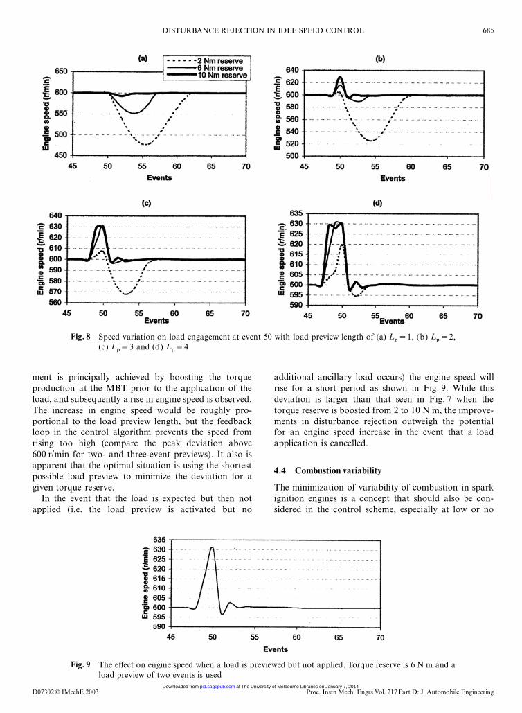
In Fig. 8 the engine speed response for a load applicationat di�erent torque reserves and using di�erent load pre-view lengths is plotted. In comparison with both theno-load preview case and the torque-boosted case of theprevious two sections, there is a signi�cant improvementin both engine speed response and preview length requiredto obtain a given deviation. For the 10 N m torque reservea load preview of one event is all that is required to preventthe engine speed going below the desired speed, while forthe 2 and 6 N m torque reserves longer previews arerequired to allow the manifold pressure to increase to alevel that will allow the disturbance to be rejected withoutany deviation below the desired speed.
The deviation below the desired speed for each of thethree cases is listed in Table 1. From Table 1 it is clearthat the peak deviation under the desired speed is dra-matically reduced with a load preview. This improve-
Table 1 Maximum deviations in r/min below desired speed of600 r/min after 10 N m load engagement
Fig. 8 Speed variation on load engagement at event 50 with load preview length of (a) Lp=1, (b) L
p=2,
(c) Lp=3 and (d) L
p=4
ment is principally achieved by boosting the torqueproduction at the MBT prior to the application of theload, and subsequently a rise in engine speed is observed.The increase in engine speed would be roughly pro-portional to the load preview length, but the feedbackloop in the control algorithm prevents the speed fromrising too high (compare the peak deviation above600 r/min for two- and three-event previews). It also isapparent that the optimal situation is using the shortestpossible load preview to minimize the deviation for agiven torque reserve.
In the event that the load is expected but then notapplied (i.e. the load preview is activated but no
Fig. 9 The e�ect on engine speed when a load is previewed but not applied. Torque reserve is 6 N m and aload preview of two events is used
additional ancillary load occurs) the engine speed willrise for a short period as shown in Fig. 9. While thisdeviation is larger than that seen in Fig. 7 when thetorque reserve is boosted from 2 to 10 N m, the improve-ments in disturbance rejection outweigh the potentialfor an engine speed increase in the event that a loadapplication is cancelled.
4.4 Combustion variability
The minimization of variability of combustion in sparkignition engines is a concept that should also be con-sidered in the control scheme, especially at low or no
at The University of Melbourne Libraries on January 7, 2014pid.sagepub.comDownloaded from
load where indices such as coe�cient of variation orvariance of IMEP can be high. The control scheme musthave su�cient robustness to cope with combustion-induced variations. For the �nal simulations cyclic vari-ations were considered in the torque production usingequations (11) and (12). Figure 10 demonstrates thevariation in the torque produced by combustion at theoperating points indicated with and without anadditional 10 N m ancillary load.
From a control perspective the following two scenarioswere considered in maintaining the idle speed:
1. No modi�cation was made to the control structurefrom the previous cases.
2. The cyclic variations could be predicted using themodel (11) and (12) and used to update the desiredspark retard from the MBT. This method is only validif measurements of the torque produced by combus-tion are available. While these measurements can bemade using in-cylinder pressure sensors, these sensorsare costly and unlikely to be used in a productionvehicle. A commercially more feasible approach is touse measurements of instantaneous engine speed (ora synthetic of instantaneous speed [18] ) to reconstructthe in-cylinder pressure signal as in reference [19].This information can then be readily related to com-bustion torque. There are also other bene�ts that canbe made if combustion torque measurements (eitherdirect or indirect) are available. One example is thatthe MBT surfaces described in equations (5) and (6)could potentially be updated on line using a radialbasis function network or similar function approxi-mation tool. Alternatively (or in conjunction with)this possibility is the use of an on-line estimationscheme for the combustion variability parameters aand b. Both of these options would reduce modelinaccuracies and improve performance over longertime scales in a real engine.
An example of the instantaneous engine speed responsesin the presence of combustion variability and with theapplication and removal of a 10 N m load is demonstratedin Fig. 11 for a torque reserve of 6 N m and a load preview
Fig. 10 Indicated combustion torque with cyclic variabilityon ancillary load application and removal
Fig. 11 Engine speed on application of torque disturbanceswith cyclic variation in combustion using a 6 N mtorque reserve and three-event load preview:(a) without compensation; (b) with compensation;(c) with compensation and engine speed averagedover three events (one engine revolution).
of three events. These values were chosen as they werefound in the earlier simulation to reject su�ciently the dis-turbance induced by the ancillary load. It is clear that thedeviations appear quite large, although it should beremembered that the time scale between events is veryshort and the engine speed is more realistically shown asaveraged over an engine revolution (in a six-cylinderengine this would be three combustion events). Figure 11cdepicts the engine speed that would be measured fromTDC to TDC rather than instantaneously.
The ratio of the weights in the MPC control algorithm,l/c , has been set to be relatively large in the control lawto this point to ensure good disturbance rejection.However, in the light of the large variation in indicatedtorque illustrated in Fig. 10 there are quite large variationsin the control sequence sent to the BPAV and sparkadvance. The e�ect of reducing the l/c ratio (in e�ect lowpass �ltering the ‘optimal’ BPAV duty cycle) on the controlsignals was also investigated and is demonstrated in
at The University of Melbourne Libraries on January 7, 2014pid.sagepub.comDownloaded from
Fig. 12 Control signals sent to BPAV: (a) with low cost given to change in control signals; (b) with highercost given to change in control signals
Fig. 12. In theory, as the BPAV is only meant to compen-sate for steady state torque changes, the overall perform-ance of the controller with respect to disturbance rejectionof combustion variability related torque changes shouldnot change subject to this modi�cation.
Table 2 shows data collected over 1000 events fromthe simulated engine both with and without additionalcompensation for combustion variability (and with twodi�erent l/c ratios in the BPAV control signal deri-vation). As in the previous simulations a 10 N m loadwas applied and removed every 100 events.
The �rst point to note about the data in Table 2 isthat the compensation of combustion variability usingthe spark advance results in a signi�cant improvementin the standard deviation of the engine speed and a muchhigher minimium speed. This might lead to reduced costin the engine mounts that reduce the force �uctuations(vibration) transmitted to the car body.
Another point of interest is that there is a slightimprovement in performance with 10 N m torque reserveand one-event load preview compared with the case with2 N m torque reserve and three-event load preview.From the earlier simulations it is known that both havea similar disturbance rejection capability for a known
Table 2 Comparison of performance with di�erent controller speci�cations with cycle-by-cycle combustion variations
No compensation for combustion variability Compensating for combustion variability
Standard StandardTorque deviation Minimum Mean deviation Minimum Meanreserve of engine engine engine of engine engine engineand load speed speed speed speed speed speedpreview l/c (r/min) (r/min) (r/min) (r/min) (r/min) (r/min)
load; however, the 10 N m torque reserve o�ers superiorperformance to unknown load disturbances in the formof combustion variability, as the spark advance using2 N m load preview will be saturated at the MBT forfrequent large disturbances. This e�ect is noted fromTable 2 in that the average speed throughout the simu-lation is below the desired set point for the 2 N m torquereserve. It is expected that the improvement in perform-ance will not continue inde�nitely with increasing torquereserve, however, as from equation (12) a higher com-bustion variability will be present for larger retards fromthe MBT (higher torque reserves). There is also the con-sideration of fuel economy being sacri�ced slightly bythe higher torque reserve, and therefore the most suitableapproach is likely to be to use the minimum torquereserve capable of rejecting the transient torque disturb-ances and setting the load preview accordingly to rejectknown disturbances. Of the three controller speci�ca-tions shown in Table 2, it would appear that using the6 N m torque reserve with load preview of three eventsis the most suitable.
Also, reducing the l/c weighting ratio in order toreduce the high frequency oscillations in the controlsignal can have a bene�cial e�ect on disturbance
at The University of Melbourne Libraries on January 7, 2014pid.sagepub.comDownloaded from
rejection by minimizing the reaction of the BPAV valveto the stochastic part of the combustion variability. Onceagain this improvement will not be seen inde�nitely, asthe capacity of the system to react to fast changes willbe reduced with the further reductions in the ratio of theweighting parameters. Increasing the load preview is onepossible solution to improve known disturbance rejec-tion in the case of smaller l/c ratios. Finally, while com-pensation of the cyclic variability in torque productionhas been achieved using model inversion of equation(11), it should be noted that complete disturbance rejec-tion of such highly variable sources may not be practicalin a single control step on a real engine. Thus thereduction in the weighting ratio l/c will also help toprevent the BPAV controller from overreacting todynamics such as noise or model inaccuracies. In thesame vein it may be necessary to reduce the rate of com-pensation when noise sources are considered from com-plete rejection using spark advance on the real engine ifit is found that the frequent sharp changes in sparkadvance adversely a�ect the vehicle NVH quality.
4.5 Fuel economy improvements
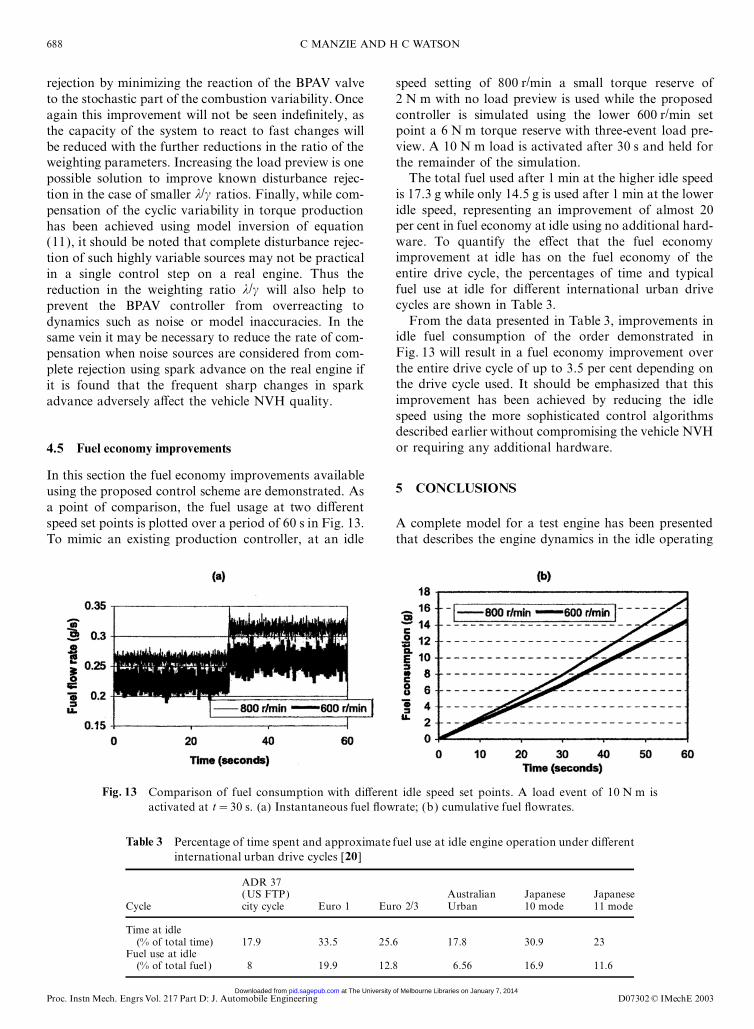
In this section the fuel economy improvements availableusing the proposed control scheme are demonstrated. Asa point of comparison, the fuel usage at two di�erentspeed set points is plotted over a period of 60 s in Fig. 13.To mimic an existing production controller, at an idle
Fig. 13 Comparison of fuel consumption with di�erent idle speed set points. A load event of 10 N m isactivated at t=30 s. (a) Instantaneous fuel �owrate; (b) cumulative fuel �owrates.
Table 3 Percentage of time spent and approximate fuel use at idle engine operation under di�erentinternational urban drive cycles [20]
ADR 37(US FTP) Australian Japanese Japanese
Cycle city cycle Euro 1 Euro 2/3 Urban 10 mode 11 mode
Time at idle(% of total time) 17.9 33.5 25.6 17.8 30.9 23
Fuel use at idle(% of total fuel ) 8 19.9 12.8 6.56 16.9 11.6
speed setting of 800 r/min a small torque reserve of2 N m with no load preview is used while the proposedcontroller is simulated using the lower 600 r/min setpoint a 6 N m torque reserve with three-event load pre-view. A 10 N m load is activated after 30 s and held forthe remainder of the simulation.
The total fuel used after 1 min at the higher idle speedis 17.3 g while only 14.5 g is used after 1 min at the loweridle speed, representing an improvement of almost 20per cent in fuel economy at idle using no additional hard-ware. To quantify the e�ect that the fuel economyimprovement at idle has on the fuel economy of theentire drive cycle, the percentages of time and typicalfuel use at idle for di�erent international urban drivecycles are shown in Table 3.
From the data presented in Table 3, improvements inidle fuel consumption of the order demonstrated inFig. 13 will result in a fuel economy improvement overthe entire drive cycle of up to 3.5 per cent depending onthe drive cycle used. It should be emphasized that thisimprovement has been achieved by reducing the idlespeed using the more sophisticated control algorithmsdescribed earlier without compromising the vehicle NVHor requiring any additional hardware.
5 CONCLUSIONS
A complete model for a test engine has been presentedthat describes the engine dynamics in the idle operating
at The University of Melbourne Libraries on January 7, 2014pid.sagepub.comDownloaded from
region. A novel algorithm has been presented to controlthe idle speed in an engine using an MPC framework.The algorithm estimates the torque disturbance and usesthis to evaluate the desired manifold pressure. Thedesired manifold pressure is then converted into a dutycycle for the BPAV using an MPC algorithm. At thesame time, deviations from the desired speed areminimized using the spark advance from the MBT.
The e�ects on disturbance rejection using variousmodi�cations to the control approach, such as thedi�erent levels of torque reserve, boosting the torquereserve prior to a load event and arti�cially increasingthe estimate of disturbance torque on an imminent loanapplication, were investigated. It was found that a pre-view of the load as short as one event could make sig-ni�cant improvements to the disturbance rejectionqualities of the controller.
Cyclic variability in combustion was also included inthe engine model, and the control scheme was adaptedto account for this new source of torque disturbanceusing a model of cycle-by-cycle combustion variations.It was found that with combustion variability consideredthe e�ect of torque reserve on deviations from the idlespeed set point was reduced. It was also found that thespeed at which the controller is allowed to react to torquedisturbances may have to be reduced when combustionvariance is considered in order to maintain a smoothcontrol signal.
The improvements in fuel economy achievable byreductions in vehicle idle speed have been estimated tobe as large as 3.5 per cent over the entire drive cycle.Furthermore, reductions in vehicle NVH may result inimproved driver perceptions of engine stability andreduced cost in engine mounts. Extensions of the algor-ithms presented require a synthetic combustion torquemeasurement, which can be made available throughinstantaneous engine speed measurements; however, thecomplexity of the algorithm can be simpli�ed under basicassumptions to allow its use in a standard productionengine control unit.
ACKNOWLEDGEMENT
This research was supported with the assistance of anAustralian Research Council grant.
REFERENCES
1 Gangopadhyay, A. and Meckl, P. Multivariable PI tuningfor disturbance rejection and application to engine idlespeed control simulation. Int. J. Control, 2001, 74(10),1033–1041.
2 Li, X. and Yurkovich, S. Sliding mode control of delayedsystems with application to engine idle speed control. IEEETrans. Control Systems Technol., 2001, 9(6), 802–810.
3 Butts, K., Sivashankar, N. and Sun, J. Application of L1optimal control to the engine idle speed control problem.IEEE Trans. Control Systems Technol., 1999. 7(2),258–270.
4 Puskorius, G., Feldkamp, L. and Davis Jr, L. Dynamicneural network methods applied to on-vehicle idle speedcontrol. Proc. IEEE, 1996, 84(10), 1407–1420.
5 Manzie, C., Palaniswami, M. and Watson, H. Gaussian net-works for fuel injection control. Proc. Instn Mech. Engrs,Part D: J. Automobile Engineering, 2001, 215(10),1053–1068.
6 Manzie, C., Palaniswami, M., Ralph, D., Watson, H. andYi, X. Model predictive control of a fuel injection systemwith a radial basis function network observer. Trans.ASME, J. Dynamic Systems, Measmt Control, 2002,124(4), 648–658.
7 Hrovat, D. and Sun, J. Models and control methodologiesfor IC engine idle speed control design. Control EngngPractice, 1997, 5(8), 1093–1100.
8 Li, X. and Yurkovich, S. Neural network based, discreteadaptive sliding mode control for idle speed regulation inIC engines. J. Dynamic Systems, Measmt Control, 2000,122, 269–275.
9 Ford, R. Robust automotive idle speed control in a novelframework. PhD dissertation, Department of Engineering,University of Cambridge, 2000.
10 Won, M., Choi, S.-B. and Hedrick, J. K. Air-to-fuel ratiocontrol of spark ignition engines using Gaussian networksliding control. IEEE Control Systems Technol, 1998,678–687.
11 Cho, D. and Hedrick, J. K. Automotive powertrain model-ling for control. Trans. ASME, 1989, 111, 568–576.
12 Hendricks, E., Chevalier, A., Jensen, M., Sorenson, S. C.,Trumpy, D. and Asik, J. Modeling of the intake manifold�lling dynamics. SAE paper 960037, 1996.
13 Manzie, C., Watson, H. and Baker, P. Modeling the e�ectsof combustion variability for application to idle speed con-trol in SI engines. In SAE Powertrain and Fluid SystemsConference, 2002, San Diego, California, SAE paper02FFL-271, 2002.
14 Polak, E. and Yang, T. H. Moving horizon control of linearsystems with input saturation and plant uncertainty. Part 1.Robustness. Int. J. Control, 1993, 613–638.
15 Polak, E. and Yang, T. H. Moving horizon control of linearsystems with input saturation and plant uncertainty. Part 2.Disturbance rejection and tracking. Int. J. Control, 1993,639–663.
16 Mayne, D. Q. and Michalska, H. Model predictive controlof nonlinear systems. In American Control Conference,1991.
17 Manzie, C., Watson, H. and Palaniswami, M. A modelpredictive approach to disturbance rejection in idle speedcontrol. In Asian Control Conference, Singapore, 2002.
18 Moskwa, J. J., Wang, W. and Bucheger, D. J. A new meth-odology for use in engine diagnostics and control, utilising‘synthetic’ engine variables: theoretical and experimentalresults. Trans. ASME, 2001, 123, 528–534.
19 Moro, D., Cavina, N. and Ponti, F. In-cylinder pressurereconstruction based on instantaneous engine speed signal.J. Engng Gas Turbines Pwr, 2002, 124, 220–225.
20 Watson, H. C., Liu, Y. and Kyhaw, Z. H. A comparison ofthe e�ect of down-sizing versus component improvements
at The University of Melbourne Libraries on January 7, 2014pid.sagepub.comDownloaded from