9
1 Iron core technology Low cogging force Integrated with hall sensors High force Zero net attraction force ACM-D Series (Patented) High Force Iron Core Brushless Linear Motor
1
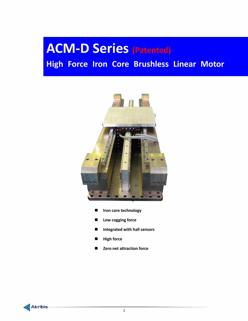
Iron core technology
Low cogging force
Integrated with hall sensors
High force
Zero net attraction force
ACM-D Series (Patented) High Force Iron Core Brushless Linear Motor
2
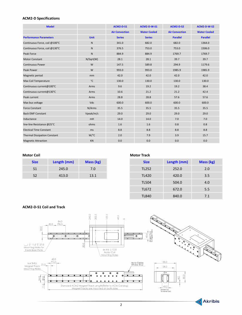
ACM2-D Specifications
Model ACM2-D-S1 ACM2-D-W-S1 ACM2-D-S2 ACM2-D-W-S2
Air Convection Water Cooled Air Convection Water Cooled
Performance Parameters Unit Series Series Parallel Parallel
Continuous Force, coil @100°C N 341.0 682.0 682.0 1364.0
Continuous Force, coil @130°C N 376.5 753.0 753.0 1506.0
Peak Force N 884.9 884.9 1769.7 1769.7
Motor Constant N/Sqrt(W) 28.1 28.1 39.7 39.7
Continuous Power W 147.5 589.8 294.9 1179.6
Peak Power W 993.0 993.0 1985.9 1985.9
Magnetic period mm 42.0 42.0 42.0 42.0
Max Coil Temperature °C 130.0 130.0 130.0 130.0
Continuous current@100°C Arms 9.6 19.2 19.2 38.4
Continuous current@130°C Arms 10.6 21.2 21.2 42.4
Peak current Arms 28.8 28.8 57.6 57.6
Max bus voltage Vdc 600.0 600.0 600.0 600.0
Force Constant N/Arms 35.5 35.5 35.5 35.5
Back EMF Constant Vpeak/m/s 29.0 29.0 29.0 29.0
Inductance mH 14.0 14.0 7.0 7.0
line-line Resistance @25°C ohms 1.6 1.6 0.8 0.8
Electical Time Constant ms 8.8 8.8 8.8 8.8
Thermal Dissipation Constant W/°C 2.0 7.9 3.9 15.7
Magnetic Attraction KN 0.0 0.0 0.0 0.0
Motor Coil Motor Track
Size Length (mm) Mass (kg) Size Length (mm) Mass (kg)
S1 245.0 7.0 TL252 252.0 2.0
S2 413.0 13.1 TL420 420.0 3.5
TL504 504.0 4.0
TL672 672.0 5.5
TL840 840.0 7.1
ACM2-D-S1 Coil and Track
3
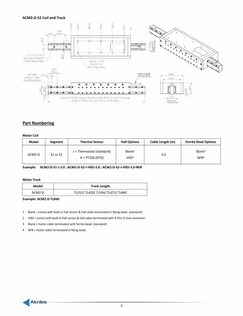
ACM2-D-S2 Coil and Track
Part Numbering
Motor Coil
Model Segment Thermal Sensor Hall Options Cable Length (m) Ferrite Bead Options
ACM2-D S1 or S2 J = Thermostat (standard)
K = PT100 (RTD)
Blank1
H9D2 3.0
Blank3
NFB4
Example: ACM2-D-S1-J-3.0 ; ACM2-D-S2-J-H9D-3.0 ; ACM2-D-S2-J-H9D-3.0-NFB
Motor Track
Model Track Length
ACM2-D TL252/ TL420/ TL504/ TL672/ TL840
Example: ACM2-D-TL840
1 Blank = comes with built-in hall sensor & hall cable terminated in flying leads. (standard)
2 H9D = comes with built-in hall sensor & hall cable terminated with 9-Pins D-Sub connector.
3 Blank = motor cable terminated with ferrite bead. (standard)
4 NFB = motor cable terminated in flying leads.
4
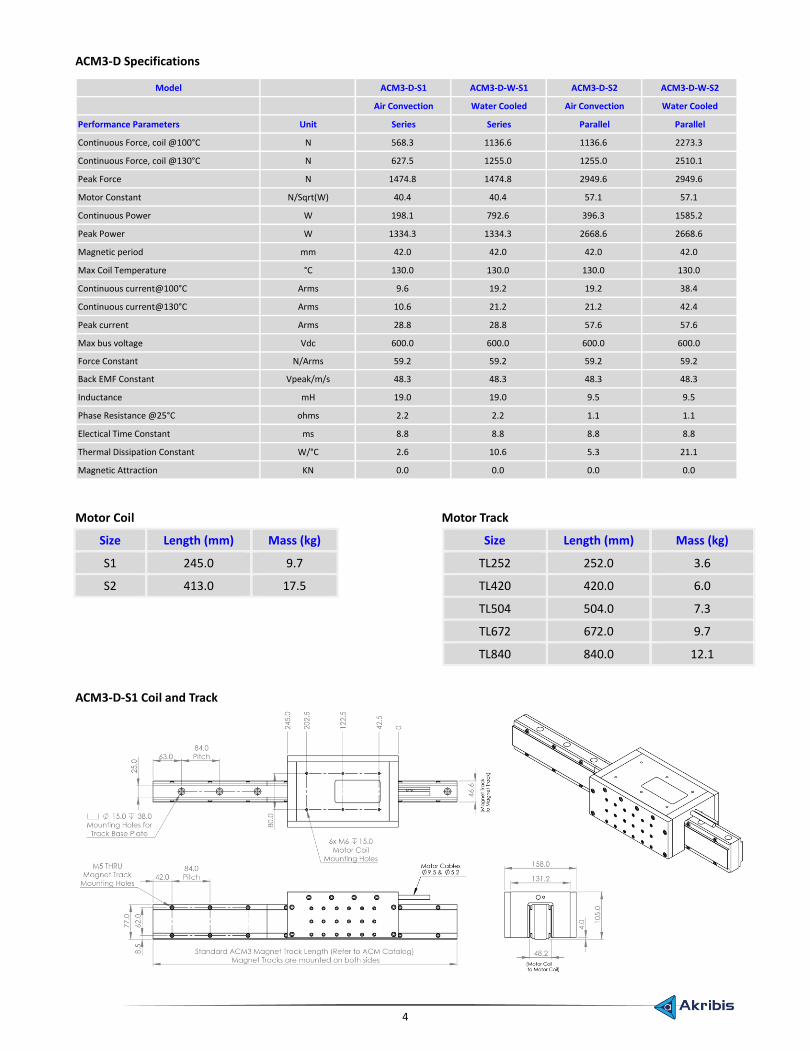
ACM3-D Specifications
Model ACM3-D-S1 ACM3-D-W-S1 ACM3-D-S2 ACM3-D-W-S2
Air Convection Water Cooled Air Convection Water Cooled
Performance Parameters Unit Series Series Parallel Parallel
Continuous Force, coil @100°C N 568.3 1136.6 1136.6 2273.3
Continuous Force, coil @130°C N 627.5 1255.0 1255.0 2510.1
Peak Force N 1474.8 1474.8 2949.6 2949.6
Motor Constant N/Sqrt(W) 40.4 40.4 57.1 57.1
Continuous Power W 198.1 792.6 396.3 1585.2
Peak Power W 1334.3 1334.3 2668.6 2668.6
Magnetic period mm 42.0 42.0 42.0 42.0
Max Coil Temperature °C 130.0 130.0 130.0 130.0
Continuous current@100°C Arms 9.6 19.2 19.2 38.4
Continuous current@130°C Arms 10.6 21.2 21.2 42.4
Peak current Arms 28.8 28.8 57.6 57.6
Max bus voltage Vdc 600.0 600.0 600.0 600.0
Force Constant N/Arms 59.2 59.2 59.2 59.2
Back EMF Constant Vpeak/m/s 48.3 48.3 48.3 48.3
Inductance mH 19.0 19.0 9.5 9.5
Phase Resistance @25°C ohms 2.2 2.2 1.1 1.1
Electical Time Constant ms 8.8 8.8 8.8 8.8
Thermal Dissipation Constant W/°C 2.6 10.6 5.3 21.1
Magnetic Attraction KN 0.0 0.0 0.0 0.0
Motor Coil Motor Track
Size Length (mm) Mass (kg) Size Length (mm) Mass (kg)
S1 245.0 9.7 TL252 252.0 3.6
S2 413.0 17.5 TL420 420.0 6.0
TL504 504.0 7.3
TL672 672.0 9.7
TL840 840.0 12.1
ACM3-D-S1 Coil and Track
5
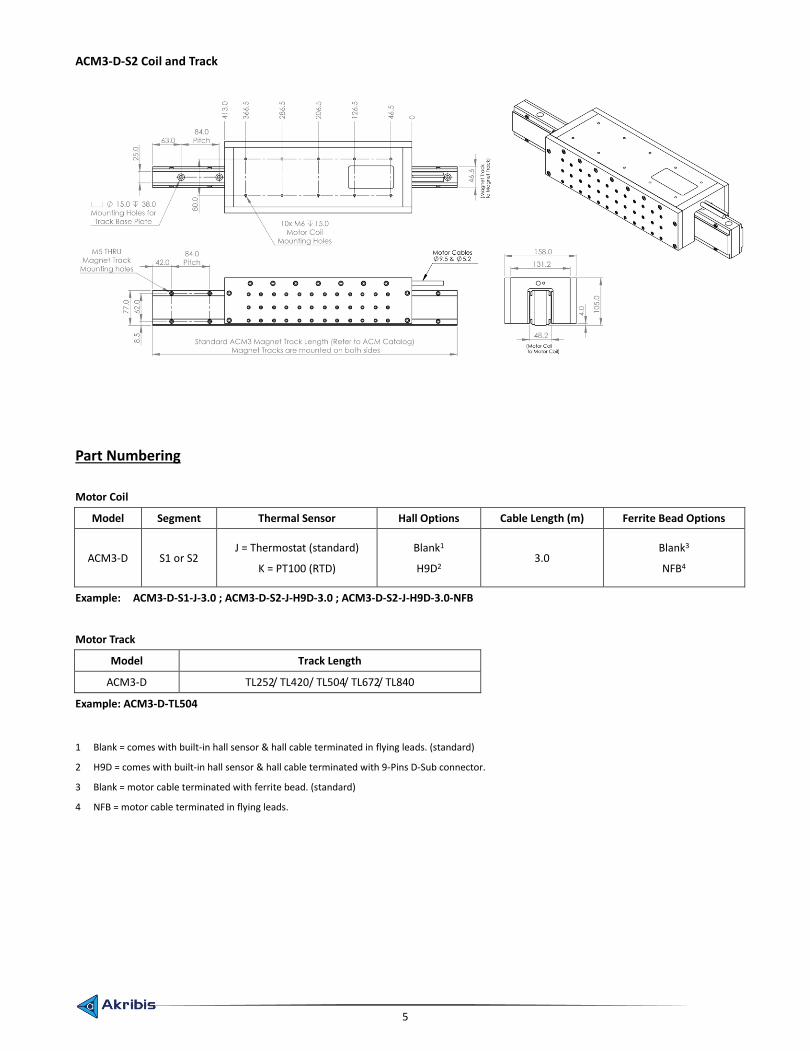
ACM3-D-S2 Coil and Track
Part Numbering
Motor Coil
Model Segment Thermal Sensor Hall Options Cable Length (m) Ferrite Bead Options
ACM3-D S1 or S2 J = Thermostat (standard)
K = PT100 (RTD)
Blank1
H9D2 3.0
Blank3
NFB4
Example: ACM3-D-S1-J-3.0 ; ACM3-D-S2-J-H9D-3.0 ; ACM3-D-S2-J-H9D-3.0-NFB
Motor Track
Model Track Length
ACM3-D TL252/ TL420/ TL504/ TL672/ TL840
Example: ACM3-D-TL504
1 Blank = comes with built-in hall sensor & hall cable terminated in flying leads. (standard)
2 H9D = comes with built-in hall sensor & hall cable terminated with 9-Pins D-Sub connector.
3 Blank = motor cable terminated with ferrite bead. (standard)
4 NFB = motor cable terminated in flying leads.

6
ACM4-D Specifications
Model ACM4-D-S1 ACM4-D-W-S1 ACM4-D-S2 ACM4-D-W-S2
Air Convection Water Cooled Air Convection Water Cooled
Performance Parameters Unit Series Series Parallel Parallel
Continuous Force, coil @100°C N 1136.6 2273.3 2273.3 4546.6
Continuous Force, coil @130°C N 1255.0 2510.1 2510.1 5020.2
Peak Force N 2949.6 2949.6 5899.2 5899.2
Motor Constant N/Sqrt(W) 62.2 62.2 88.0 88.0
Continuous Power W 333.6 1334.5 667.2 2669.0
Peak Power W 2246.6 2246.6 4493.2 4493.2
Magnetic period mm 42.0 42.0 42.0 42.0
Max Coil Temperature °C 130.0 130.0 130.0 130.0
Continuous current@100°C Arms 9.6 19.2 19.2 38.4
Continuous current@130°C Arms 10.6 21.2 21.2 42.4
Peak current Arms 28.8 28.8 57.6 57.6
Max bus voltage Vdc 600.0 600.0 600.0 600.0
Force Constant N/Arms 118.4 118.4 118.4 118.4
Back EMF Constant Vpeak/m/s 96.7 96.7 96.7 96.7
Inductance mH 38.0 38.0 19.0 19.0
Phase Resistance @25°C ohms 3.6 3.6 1.8 1.8
Electical Time Constant ms 10.5 10.5 10.5 10.5
Thermal Dissipation Constant W/°C 4.4 17.8 8.9 35.6
Magnetic Attraction KN 0.0 0.0 0.0 0.0
Motor Coil Motor Track
Size Length (mm) Mass (kg) Size Length (mm) Mass (kg)
S1 245.0 17.8 TL252 252.0 6.4
S2 413.0 32.1 TL420 420.0 10.6
TL504 504.0 12.9
TL672 672.0 17.0
TL840 840.0 21.2
ACM4-D-S1 Coil and Track
7
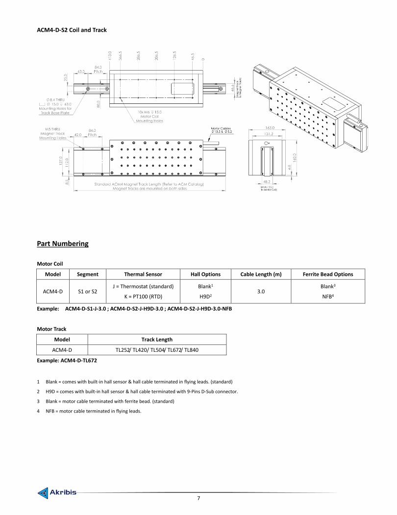
ACM4-D-S2 Coil and Track
Part Numbering
Motor Coil
Model Segment Thermal Sensor Hall Options Cable Length (m) Ferrite Bead Options
ACM4-D S1 or S2 J = Thermostat (standard)
K = PT100 (RTD)
Blank1
H9D2 3.0
Blank3
NFB4
Example: ACM4-D-S1-J-3.0 ; ACM4-D-S2-J-H9D-3.0 ; ACM4-D-S2-J-H9D-3.0-NFB
Motor Track
Model Track Length
ACM4-D TL252/ TL420/ TL504/ TL672/ TL840
Example: ACM4-D-TL672
1 Blank = comes with built-in hall sensor & hall cable terminated in flying leads. (standard)
2 H9D = comes with built-in hall sensor & hall cable terminated with 9-Pins D-Sub connector.
3 Blank = motor cable terminated with ferrite bead. (standard)
4 NFB = motor cable terminated in flying leads.
8
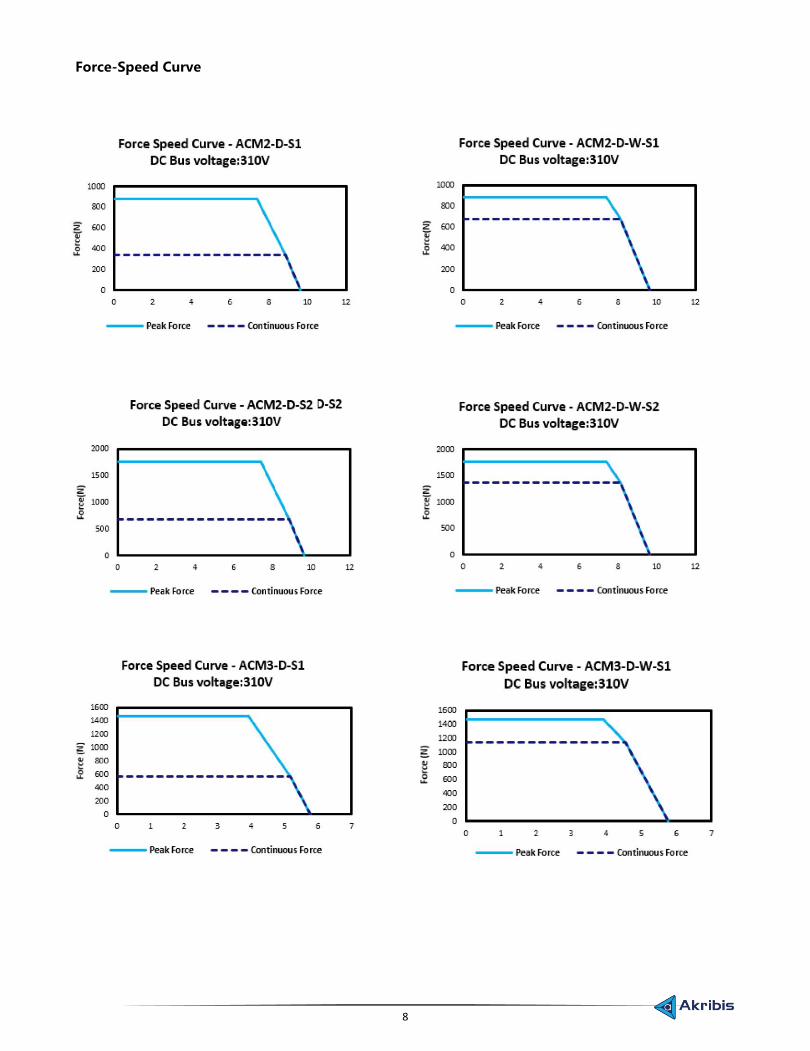
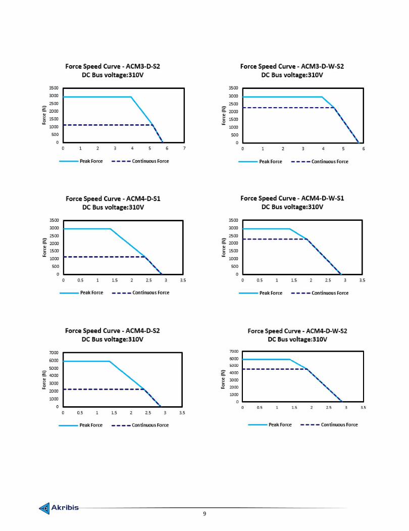
Force-Speed Curve
9


