International Multidimensional Engine Modeling User’s Group Meeting April 2, 2006, Detroit, MI Advanced Turbulent Heat Transfer Modeling for IC-Engine Applications Using AVL FIRE R. Tatschl, B. Basara, J. Schneider AVL List GmbH, Graz K. Hanjalic, M. Popovac TU-Delft A. Brohmer, J. Mehring Ford Werke AG, Köln ABSTRACT The realistic modeling of wall-heat transfer in 3D-CFD is a necessary prerequisite for the accurate calculation of IC-engine related flow and combustion processes, and for providing reliable boundary conditions for components thermal analysis. Regarding the predictive capabilities and universality of turbulent heat transfer models it turns out that improved models are needed to fully satisfy present and future demands. The present article focuses on advanced modeling of turbulence and turbulent wall-heat transfer suitable for engine applications. Verification of the model is achieved for idealized flow configurations via comparison of calculated results with experimental and LES-data. The applicability of the newly developed model to engine development related tasks is demonstrated for a calculation of the cylinder head and cylinder block metal temperatures in a modern state- of-the-art 4-valve gasoline engine. 1 MODELING For predicting wall friction and heat transfer in wall-bounded turbulent flows, in the frame of RANS methods two approaches have been in use in Computational Fluid Dynamics (CFD): the high-Re-number models with wall functions (WF approach), where some empirical laws are used to bridge the thin viscous and conductive sublayers close to a solid wall, and the integration up to a solid wall (ItW approach) using low-Re-number and wall-proximity models and the exact wall boundary conditions. Industrial CFD users have shown a clear tendency to use finer computational meshes, but with the conventional EVMs and aimed primarily towards obtaining grid-independent solutions and thus eliminating the insufficient grid resolution as one of the major uncertainties in CFD. This trend has brought into focus again the treatment of wall boundary conditions. Namely, in the course of grid refinement, the first near-wall cell center („grid point“) appears more often closer to the wall than the conventional wall function approach would permit (expressed in inner-wall scaled distance, y 1 + >30). However, for the time being and in the near future, in most applications - especially in engine flows - the typical grid is still not sufficiently fine (or at least not everywhere in the solution domain) to satisfy the requirements for the integration up to the wall (y 1 + <1).
Transcript
International Multidimensional Engine ModelingUser’s Group Meeting
April 2, 2006, Detroit, MI
Advanced Turbulent Heat Transfer Modeling forIC-Engine Applications Using AVL FIRE
R. Tatschl, B. Basara, J. SchneiderAVL List GmbH, Graz
K. Hanjalic, M. PopovacTU-Delft
A. Brohmer, J. MehringFord Werke AG, Köln
ABSTRACT
The realistic modeling of wall-heat transfer in 3D-CFD is a necessary prerequisite for theaccurate calculation of IC-engine related flow and combustion processes, and for providingreliable boundary conditions for components thermal analysis. Regarding the predictivecapabilities and universality of turbulent heat transfer models it turns out that improved modelsare needed to fully satisfy present and future demands.The present article focuses on advanced modeling of turbulence and turbulent wall-heat transfersuitable for engine applications. Verification of the model is achieved for idealized flowconfigurations via comparison of calculated results with experimental and LES-data. Theapplicability of the newly developed model to engine development related tasks is demonstratedfor a calculation of the cylinder head and cylinder block metal temperatures in a modern state-of-the-art 4-valve gasoline engine.
1 MODELING
For predicting wall friction and heat transfer in wall-bounded turbulent flows, in the frame ofRANS methods two approaches have been in use in Computational Fluid Dynamics (CFD): thehigh-Re-number models with wall functions (WF approach), where some empirical laws areused to bridge the thin viscous and conductive sublayers close to a solid wall, and theintegration up to a solid wall (ItW approach) using low-Re-number and wall-proximity modelsand the exact wall boundary conditions.Industrial CFD users have shown a clear tendency to use finer computational meshes, but withthe conventional EVMs and aimed primarily towards obtaining grid-independent solutions andthus eliminating the insufficient grid resolution as one of the major uncertainties in CFD.This trend has brought into focus again the treatment of wall boundary conditions. Namely, inthe course of grid refinement, the first near-wall cell center („grid point“) appears more oftencloser to the wall than the conventional wall function approach would permit (expressed ininner-wall scaled distance, y1
+>30). However, for the time being and in the near future, in mostapplications - especially in engine flows - the typical grid is still not sufficiently fine (or at leastnot everywhere in the solution domain) to satisfy the requirements for the integration up to thewall (y1
+<1).
Hence, a new Compound Wall Treatment (CWT) for velocity and temperature fields for flowsencountered in real life engines was developed [1]. The CWT is a blend of wall functions with arobust integration-to-the-wall (ItW) model. For this purpose, Generalized Wall Functions(GWF), based on the Analytical WF approach, were introduced. For robust integration up to thewall, a new three-equation eddy-viscosity ζ-f model was developed.
1.1 Generalised wall functions (GWF)
In order to derive new generalized wall functions that are not constrained by the commonequilibrium assumptions, the momentum and energy equations over the first near-wall cell arefirst reformulated as (here shown only for the momentum equation) and then integratedanalytically using a single – supposedly universal – assumption on the nondimensional eddyviscosity variation over the cell [1]. The resulting wall shear and the universal velocity variationover the turbulent part of the first near-wall cell are expressed as:
( )
tan
lnv
w yyv
C yUu
yu
τ
τ
κτ
µ κ
−=
+
( )1 lnU Eyκψ
+ +=
tan1 C yU
ψκ
+ +
+= − 3tanU U U pC U Vt x y xuτ
ν ρ ρ ρ+ ⎡ ⎤∂ ∂ ∂ ∂= + + +⎢ ⎥∂ ∂ ∂ ∂⎣ ⎦
Obviously, for an equilibrium wall boundary layer, Ctan≈0 and ψ≈1, thus the generalized wallfunctions reduce to the standard ones. The treatment of the energy equation and wall functionsfor the temperature (or enthalpy) is analogous. For the turbulent properties, the conventionalwall-function-treatment is followed.
1.2 The ζ-f model for Integration up to the Wall (ItW)
In order to improve the numerical stability and robustness of the original υ2 -f rationale, thepresent model solves the transport equation for the ratio ζ =υ2/k, instead for υ2 [2]. This variablecan be regarded as a time scale ratio, or a normalized velocity scale. Following themathematical transformation, the transport equation for ζ is obtained from equations for k andυ2:
⎥⎥⎦
⎤
⎢⎢⎣
⎡
∂∂
⎟⎟⎠
⎞⎜⎜⎝
⎛+
∂∂
+−=k
t
kk xx
Pk
fDtD ζ
σννζζ
ζ
which is solved together with the equation for the elliptic relaxation function f
2
22 '
121 21
3k
k
Pff L C CTx
ζε
∂ ⎛ ⎞⎛ ⎞− = − + −⎜ ⎟⎜ ⎟∂ ⎝ ⎠⎝ ⎠where L and T are the characteristic turbulence length and time scale respectively. At the wall,ζ ω =0 and the wall boundary condition for f becomes:
2
2 pw
pf
yνζ
= −
Using ζ as the velocity scale, the turbulent viscosity is defined as νt=cµζkT, where T is the timescale. The model is closed by solving also equations for k and ε. More details are provided in[1] and in [2].
1.3 Compound Wall Treatment (CWT)
In order to arrive at a general, mesh-quality-insensitive wall model that should be applicableirrespective of where the wall-nearest cell center is placed, a compound wall treatment (CWT)was developed, which provides accurate boundary conditions for all variables considered in asingle computational procedure. The model reduces to the GWF when the first grid point is infully turbulent region, and to the ItW when it lies in the molecular sublayer. This approachespecially offers advantages when the near-wall mesh is finer than the typical wall-functionmesh, but still not sufficiently fine to meet the requirements for the direct integration up to thewall.As a basis for providing smooth expressions that satisfy both the molecular and turbulentasymptotes, the blending approach of Kader [3] was adopted.
1.4 Some Illustrations
The compound wall treatment (CWT) and its constituents, the generalized wall functions(GWF) and the Integration up to the wall (ItW) with the ζ−f model, have been thoroughly testedin a range of generic test flows, for which experimental or LES data are available in theliterature, using several different grid densities and near-wall clustering.
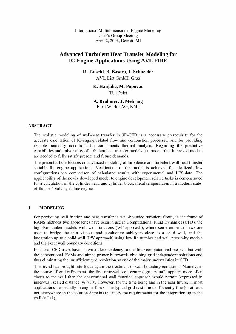
Figure 1 Velocity profiles at different locations in a channel with periodicconstrictions. Lines: computations with υ2 -f and ζ-f model. Symbols: Large Eddy
SimulationsFor some of the flows also heat transfer data are available, making it possible to validate theheat transfer model. In addition all models have been tested in a fully-developed plane channelflow and compared with the available experiments and DNS data.
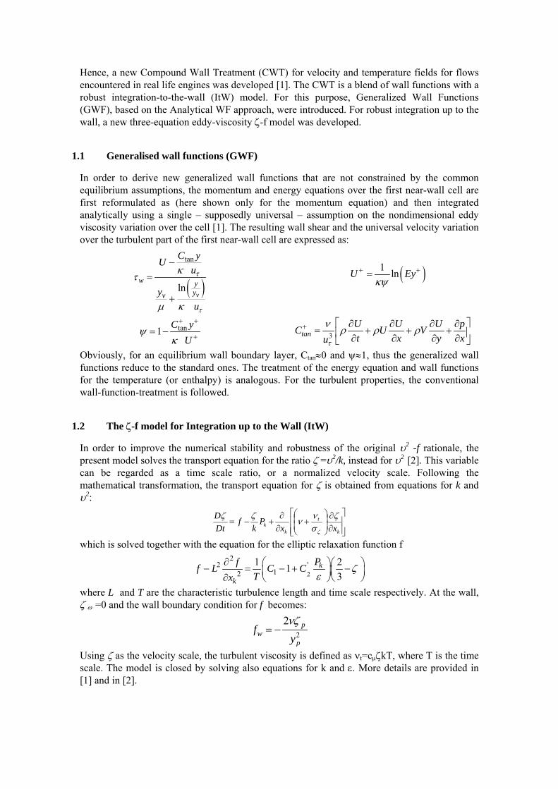
Figure 2 Normally impinging round jet. Nusselt number along the impingement plate.Left: Re=23000. Right: Re=70000
A selection of results shown here illustrates the performance of the newly developed near-wallmodels. More information and details can be found [1]. We begin with the comparison of thenew ζ−f model with the original υ2 -f model in a channel flow with periodic smoothconstrictions, compared with the finely-resolved LES of [4]. Figure 1 shows very similarperformances of the two models, with a slight superiority of ζ−f. Both models agree very wellwith the LES data.The next figure, Figure 2, shows in parallel the performances of the ItW and CWT in a single,normally impinging round jet at relatively high Re numbers. Computations are shown for twodifferent grids, a fine one in which the wall-nearest cell center is located at y+
1O(1) whereeffectively the direct ItW is automatically applied, and a moderately coarse grid with y+
1O(20) ,i.e. in the outer buffer zone, where CWT is in play. Predicting heat transfer appears to bechallenging, especially around the stagnation point, where none of the approaches is fullysatisfactory. It is noted, however, that these predictions are generally much superior to any otherEVM computations reported in the literature, and especially those by the standard k-ε model.
2 MODEL VALIDATION
Validation of the hybrid ζ-f/CWT model has been achieved via calculation of the structuralcomponent temperatures in a 4-valve gasoline engine under firing conditions and comparison ofthe calculation results with the corresponding experimentally obtained data. The calculation ofthe structural component temperatures was based upon a coupled CFD/FEM approach adoptinggas-side and water-side fluid heat transfer data. The experimental temperature data wereobtained via thermocouples applied to the cylinder head, liner and piston.In the following, the experimental and numerical studies are described together with the overallworkflow for performing the coupled CFD/FEM approach. Selected results of flow and heattransfer are shown to highlight the differences between the standard wall-function approach andthe newly developed CWT model, and finally a comparison of the calculated temperaturedistribution in the cylinder head area is compared to the experimentally obtained data.
2.1 Temperature Measurements
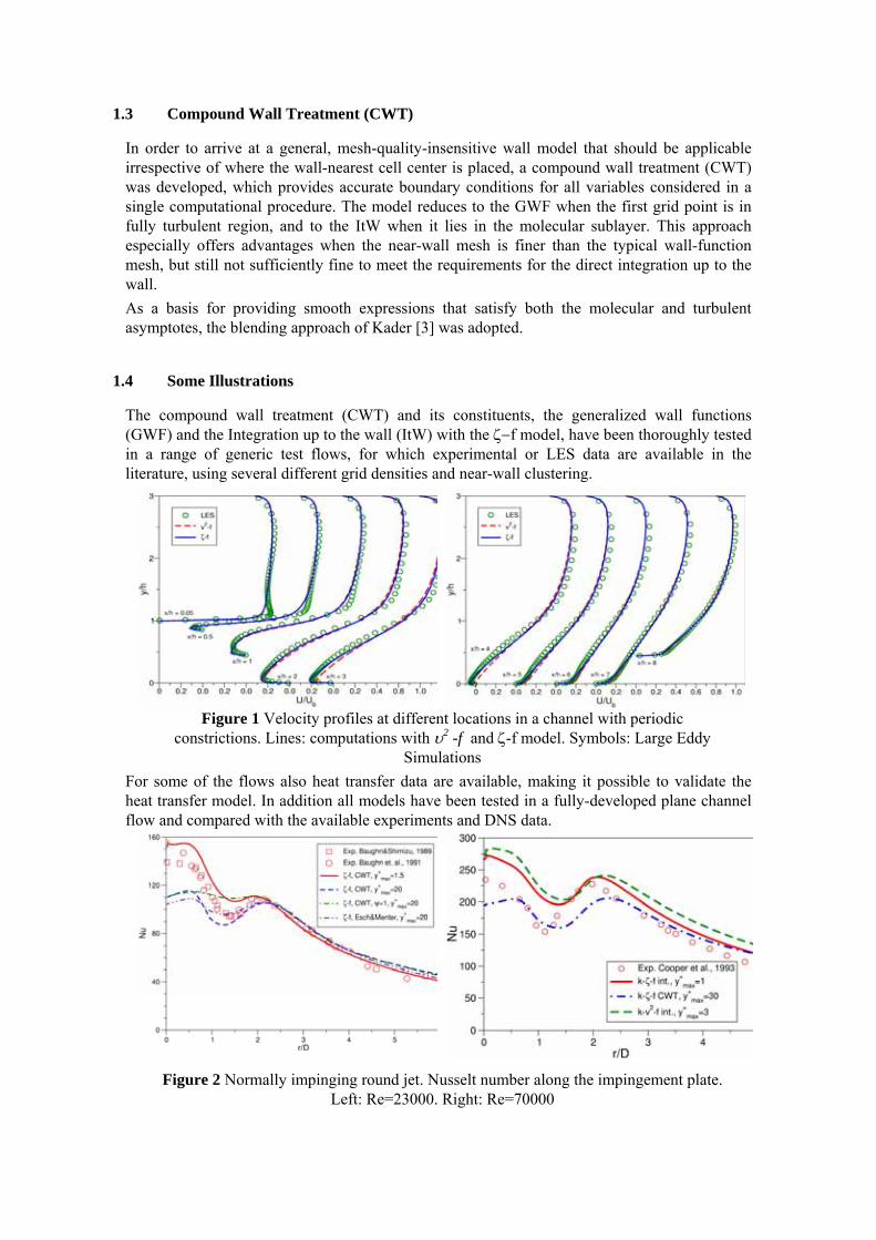
The purpose of the experimental investigations was to provide detailed data of structuralcomponent temperatures for the cylinder head, the liner and the piston for a broad range ofengine operating conditions. The engine under investigation was the FORD 1.6l Sigma Enginewith the basic technical data summarized in Figure 3.
Figure 3 Technical data of investigated engine
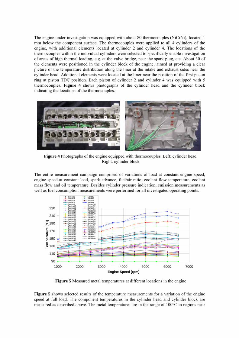
The engine under investigation was equipped with about 80 thermocouples (NiCrNi), located 1mm below the component surface. The thermocouples were applied to all 4 cylinders of theengine, with additional elements located at cylinder 2 and cylinder 4. The locations of thethermocouples within the individual cylinders were selected to specifically enable investigationof areas of high thermal loading, e.g. at the valve bridge, near the spark plug, etc. About 30 ofthe elements were positioned in the cylinder block of the engine, aimed at providing a clearpicture of the temperature distribution along the liner at the intake and exhaust sides near thecylinder head. Additional elements were located at the liner near the position of the first pistonring at piston TDC position. Each piston of cylinder 2 and cylinder 4 was equipped with 5thermocouples. Figure 4 shows photographs of the cylinder head and the cylinder blockindicating the locations of the thermocouples.
Figure 4 Photographs of the engine equipped with thermocouples. Left: cylinder head.Right: cylinder block
The entire measurement campaign comprised of variations of load at constant engine speed,engine speed at constant load, spark advance, fuel/air ratio, coolant flow temperature, coolantmass flow and oil temperature. Besides cylinder pressure indication, emission measurements aswell as fuel consumption measurements were performed for all investigated operating points.
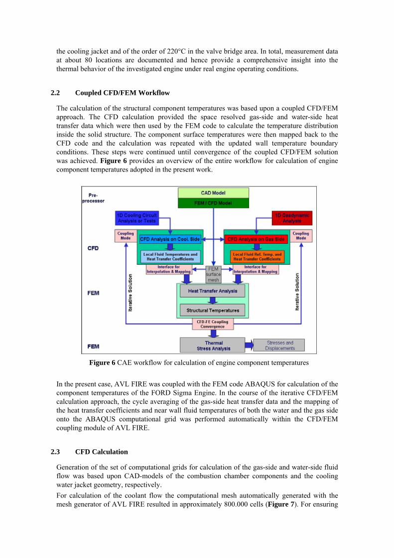
Figure 5 Measured metal temperatures at different locations in the engine
Figure 5 shows selected results of the temperature measurements for a variation of the enginespeed at full load. The component temperatures in the cylinder head and cylinder block aremeasured as described above. The metal temperatures are in the range of 100°C in regions near
the cooling jacket and of the order of 220°C in the valve bridge area. In total, measurement dataat about 80 locations are documented and hence provide a comprehensive insight into thethermal behavior of the investigated engine under real engine operating conditions.
2.2 Coupled CFD/FEM Workflow
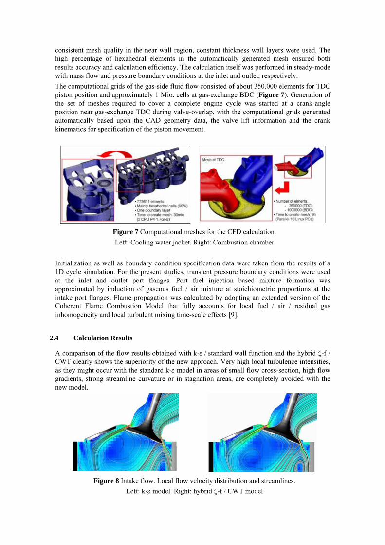
The calculation of the structural component temperatures was based upon a coupled CFD/FEMapproach. The CFD calculation provided the space resolved gas-side and water-side heattransfer data which were then used by the FEM code to calculate the temperature distributioninside the solid structure. The component surface temperatures were then mapped back to theCFD code and the calculation was repeated with the updated wall temperature boundaryconditions. These steps were continued until convergence of the coupled CFD/FEM solutionwas achieved. Figure 6 provides an overview of the entire workflow for calculation of enginecomponent temperatures adopted in the present work.
Figure 6 CAE workflow for calculation of engine component temperatures
In the present case, AVL FIRE was coupled with the FEM code ABAQUS for calculation of thecomponent temperatures of the FORD Sigma Engine. In the course of the iterative CFD/FEMcalculation approach, the cycle averaging of the gas-side heat transfer data and the mapping ofthe heat transfer coefficients and near wall fluid temperatures of both the water and the gas sideonto the ABAQUS computational grid was performed automatically within the CFD/FEMcoupling module of AVL FIRE.
2.3 CFD Calculation
Generation of the set of computational grids for calculation of the gas-side and water-side fluidflow was based upon CAD-models of the combustion chamber components and the coolingwater jacket geometry, respectively.For calculation of the coolant flow the computational mesh automatically generated with themesh generator of AVL FIRE resulted in approximately 800.000 cells (Figure 7). For ensuring
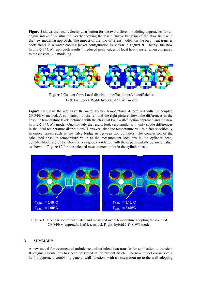
consistent mesh quality in the near wall region, constant thickness wall layers were used. Thehigh percentage of hexahedral elements in the automatically generated mesh ensured bothresults accuracy and calculation efficiency. The calculation itself was performed in steady-modewith mass flow and pressure boundary conditions at the inlet and outlet, respectively.The computational grids of the gas-side fluid flow consisted of about 350.000 elements for TDCpiston position and approximately 1 Mio. cells at gas-exchange BDC (Figure 7). Generation ofthe set of meshes required to cover a complete engine cycle was started at a crank-angleposition near gas-exchange TDC during valve-overlap, with the computational grids generatedautomatically based upon the CAD geometry data, the valve lift information and the crankkinematics for specification of the piston movement.
Figure 7 Computational meshes for the CFD calculation.Left: Cooling water jacket. Right: Combustion chamber
Initialization as well as boundary condition specification data were taken from the results of a1D cycle simulation. For the present studies, transient pressure boundary conditions were usedat the inlet and outlet port flanges. Port fuel injection based mixture formation wasapproximated by induction of gaseous fuel / air mixture at stoichiometric proportions at theintake port flanges. Flame propagation was calculated by adopting an extended version of theCoherent Flame Combustion Model that fully accounts for local fuel / air / residual gasinhomogeneity and local turbulent mixing time-scale effects [9].
2.4 Calculation Results
A comparison of the flow results obtained with k-ε / standard wall function and the hybrid ζ-f /CWT clearly shows the superiority of the new approach. Very high local turbulence intensities,as they might occur with the standard k-ε model in areas of small flow cross-section, high flowgradients, strong streamline curvature or in stagnation areas, are completely avoided with thenew model.
Figure 8 Intake flow. Local flow velocity distribution and streamlines.Left: k-ε model. Right: hybrid ζ-f / CWT model
Figure 8 shows the local velocity distribution for the two different modeling approaches for anengine intake flow situation clearly showing the less diffusive behavior of the flow field withthe new modeling approach. The impact of the two different models on the local heat transfercoefficients in a water cooling jacket configuration is shown in Figure 9. Clearly, the newhybrid ζ-f / CWT approach results in reduced peak values of local heat transfer when comparedto the classical k-ε modeling.
Figure 9 Coolant flow. Local distribution of heat transfer coefficients.Left: k-ε model. Right: hybrid ζ-f / CWT model
Figure 10 shows the results of the metal surface temperatures determined with the coupledCFD/FEM method. A comparison of the left and the right picture shows the differences in theabsolute temperature levels obtained with the classical k-ε / wall-function approach and the newhybrid ζ-f / CWT model. Qualitatively the results look very similar with only subtle differencesin the local temperature distributions. However, absolute temperature values differ specificallyin critical areas, such as the valve bridge or between two cylinders. The comparison of thecalculated absolute temperature value at the measurement locations in the cylinder head,cylinder block and piston shows a very good correlation with the experimentally obtained value,as shown in Figure 10 for one selected measurement point in the cylinder head.
Figure 10 Comparison of calculated and measured metal temperature adopting the coupledCFD/FEM approach. Left k-ε model. Right: hybrid ζ-f / CWT model
3 SUMMARY
A new model for treatment of turbulence and turbulent heat transfer for application to transientIC-engine calculations has been presented in the present article. The new model consists of ahybrid approach, combining general wall functions with an integration up to the wall adopting
TCFD = 146°CTExp. = 140°C
TCFD = 141°C TExp. = 140°C
the ζ−f turbulence model. The new hybrid ζ-f / CWT model enables a consistent treatment ofthe flow and heat transfer processes near the wall irrespective of the size of the wall-nearestcomputational cell. Verification of the model in idealized configurations shows good overallagreement of the computational results with the corresponding experimental and LES data.Comparison of the new modeling approach with the classical k-ε / wall-function treatmentclearly reveals more realistic turbulence intensity levels in regions of high streamline curvatureand small flow passages, such as valves at low lift, and in stagnation regions. Application of thenew model to the calculation of metal temperatures in a modern 4-valve gasoline engineadopting a coupled CFD/FEM method, clearly demonstrates the accuracy in predicting absolutetemperature levels.
4 ACKNOWLEDGEMENTS
Parts of the results presented in this article have been achieved within the EC-project MinNOx,contract number ENK6-CT-2001-00530.
5 LITERATURE
[1] Popovac, M. and Hanjalic, K.: Compound wall treatment for RANS computation ofcomplex turbulent flow. Proc. 3rd M.I.T. Conference, Boston, USA, 2005
[2] Hanjalic, K., Popovac, M. and Hadziabdic, M.: A Robust near-wall elliptic-relaxationeddy-viscosity turbulence model for CFD. Int. J. Heat Fluid Flow, 25, pp. 897-901, 2004
[3] Kader B.A.: Temperature and concentration profiles in fully turbulent boundary layers.Int. J. Heat Mass Transfer, 24, pp. 1541-1544, 1981
[4] Temmerman, L.: Large eddy simulation of separating flows from curved surfaces. Ph.D.thesis, Queen Mary University of London, London, U.K., 2004
[5] Baughn, J. and Shimizu, S.: Heat transfer measurements from a surface with uniform heatflux and an impinging jet. ASME Journal of Heat Transfer, 111, pp. 1096-1098, 1989
[6] Baughn, J.W., Hechanova, A.E. and Yan, X.: An experimental study of entrainmenteffects on the heat transfer from a flat surface to a heated circular impinging jet. J. HeatTransfer, 113, pp. 1023-1025, 1001
[7] Cooper, D., Jackson, D.C., Launder, B.E. and Liao, G.X.: Impinging jet studies forturbulence model assessment -- I. Flow-field experiments. Int. J. Heat Mass Transfer, 36,pp. 2675-2684, 1993
[8] Esch, T. and Menter F.R.: Heat transfer predictions based on two-equation turbulencemodels with advanced wall treatment. Turbulence, Heat and Mass Transfer, 4, pp. 633-640, 2003
[9] Patel, S.N.D.H, Bogensperger, M., Tatschl, R., Ibrahim. S.S., Hargrave, G.K.: CoherentFlame Modeling of Turbulent Combustion – A Validation Study. Proc. 2nd M.I.T.Conference, Boston, USA, 2003