34
Tesoro Anacortes Refinery Clean Products Upgrade Project Draft Environmental Impact Statement March 2017 APPENDIX 2-D: GEOTECHNICAL DRAWINGS

Tesoro Anacortes Refinery Clean Products Upgrade Project Draft Environmental Impact Statement
March 2017
APPENDIX 2-D: GEOTECHNICAL DRAWINGS

Tesoro Anacortes Refinery Clean Products Upgrade Project Draft Environmental Impact Statement
March 2017
Page Intentionally Left Blank

SCALE IN FEET
0.25 mi 0 0.25 mi 0.5 mi
PROJECT SITE LOCATION
VICINITY MAP
NTS
VICINITY MAP
Pa
cific O
ce
an
Portland
OREGON
WASHINGTON
Vancouver
Olympia
Tacoma
STATE
WASHINGTON
BRITISH COLUMBIA
WASHINGTON
Spokane
Seattle
Lynnwood
Ellensburg
Yakima
ANACORTES
Pasco
Bellingham
FILENAME: PLOT DATE:478863_JARPA-1a.dwg May 22, 2015 - 11:33am by: msparlin
PROJECT LOCATION ADDRESS:
LAT/LONG:
DATUM:
SHEET OF 20
PROPOSED PROJECT:
DATE:
REFERENCE NUMBER:
APPLICANT:
ADJACENT PROPERTY OWNERS:
IN:
COUNTY:
STATE:
NEAR / AT:
DRAWING TITLE
PROJECT SITE LOCATION
1


SCALE IN FEET
500 0 500 1000
DOCK AND CAUSEWAY
PLAN VIEW
FILENAME: PLOT DATE:NWS-2015-167_SHEET 03.dwg May 22, 2015 - 11:07am by: msparlin
PROJECT SITE LOCATION
SCALE: 1:500
SCALE IN FEET
25 0 30 60
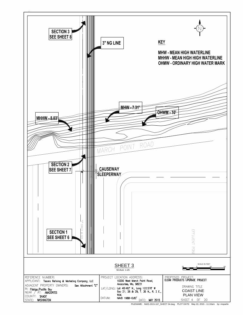
COAST LINE
PLAN VIEW
FILENAME: PLOT DATE:NWS-2015-167_SHEET 04.dwg May 22, 2015 - 11:10am by: msparlin
SHEET 3
SCALE: 1:25

COAST LINE
ELEVATION VIEW
FILENAME: PLOT DATE:NWS-2015-167_SHEET 05.dwg May 22, 2015 - 11:12am by: msparlin
ROAD CROSSING ELEVATION VIEW
NOT TO SCALE
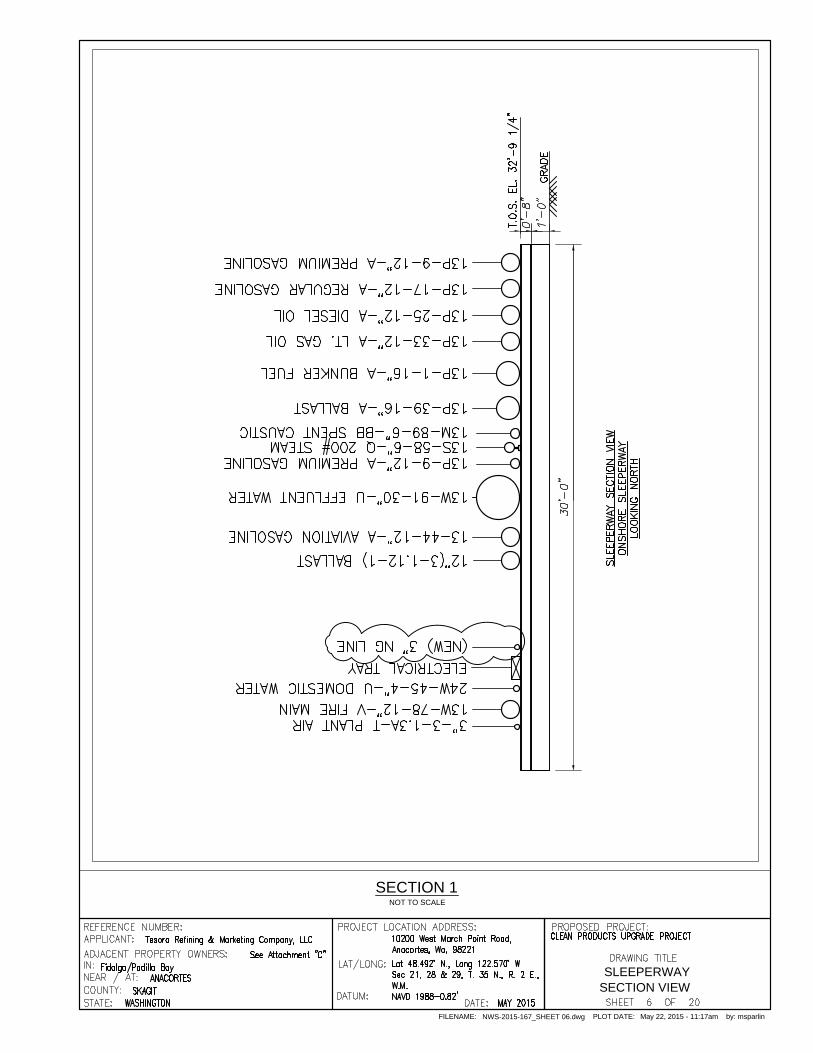
SLEEPERWAY
SECTION VIEW
FILENAME: PLOT DATE:NWS-2015-167_SHEET 06.dwg May 22, 2015 - 11:17am by: msparlin
SECTION 1
NOT TO SCALE
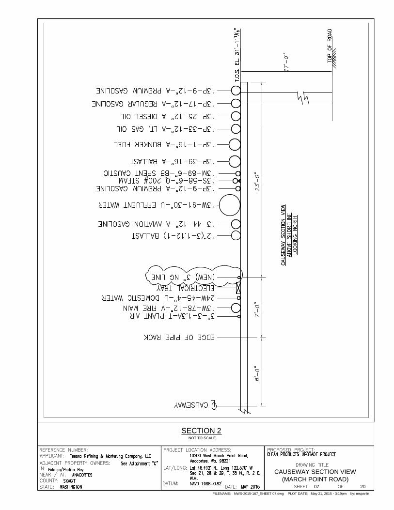
CAUSEWAY SECTION VIEW
(MARCH POINT ROAD)
FILENAME: PLOT DATE:NWS-2015-167_SHEET 07.dwg May 21, 2015 - 3:19pm by: msparlin
SECTION 2
NOT TO SCALE
07 20

CAUSEWAY
SECTION VIEW
FILENAME: PLOT DATE:NWS-2015-167_SHEET 08.dwg May 21, 2015 - 3:20pm by: msparlin
SECTION 3
NOT TO SCALE
08 20

SCALE IN FEET
20 0 25 50
DOCK SAFETY UNIT
LOCATION DRAWING
FILENAME: PLOT DATE:NWS-2015-167_SHEET 09.dwg May 21, 2015 - 3:22pm by: msparlin
DOCK
SCALE: 1:20
09 20


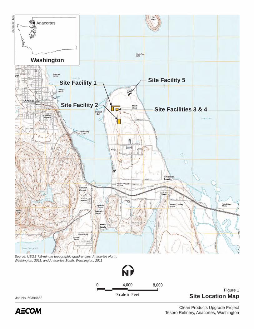
Source: USGS 7.5-minute topographic quadrangles; Anacortes North, Washington, 2011; and Anacortes South, Washington, 2011
Job No. 60394663
Figure 1
Site Location Map
3376
5169
_12.
ai
Washington
Anacortes
Site Facility 5Site Facility 1
Site Facilities 3 & 4Site Facility 2
0 4,000 8,000
Scale in Feet
Clean Products Upgrade ProjectTesoro Refinery, Anacortes, Washington

Tesoro Anacortes Refinery Clean Products Upgrade Project Draft Environmental Impact Statement
March 2017
Page Intentionally Left Blank

B-1-93
B-3-93
DM-3-00
C S
tre
et
D S
tre
et
ContractorStaging Area
ParkingArea CR-NHT
Unit
DHT-CFHUnit
Crude Distillation Unit
GasRecovery
Unit
StoresBuilding
Blending Unit
Fifth Street
Sixth Street
6A Street
DM-1-00
She
ll A
venu
e
Propane
Butane
B-18-54
B-3-54
B-5-54
B-8-54
B-9-54
U-3-11
B-6-54
B-6A-54
B-24-54
B-25-54
B-23-54
B-26-54
B-27-54
B-28-54
DM-2-00
Main Sub-Station
Storage
Machine Shop
Weld Shop
B-19-54
Cooling TowerNo. 1
E S
tre
et
F S
tre
et
B-22-54B-20-54
B-21-54
Feed Preparation
Unit
Boiler HouseControl Room
Boiler Plant
B-7-93
Anion Exchange
Fourth Street
Chemical Storage
Compressor Shed
Boiler FeedwaterStorage Tanks
Cooling Tower
Third Street
ProposedScrubber
B-8-93
W-1
731
S-1566
S-2066
Proposed Purge
Treatment
U-4-04
U-3-04
U-1-04
U-2-04
U-5-04
Boilers
CCU Control Room
Crude Unit Control Room
Consolidated Control Room
CR-NHTControl Room
Oxygen Plant SiteURS-3-00
B-48-57
’
URS-1-00
Seventh Street
A1-2-15A1-2-15
Ninth Street
UT-2-14
UT-1-14
Job No. 60394663
Clean Products Upgrade ProjectTesoro Refinery, Anacortes, Washington
Figure 2
Site Plan
33765169_13.ai
Approximate Scale in Feet
300 6000
OffloadingFacility
PUL Tank
Ethanol Tank
Diesel Tank
RUL Tank
A2-2-15
A2-3-15(PZ)A2-4-15
A2-5-15(PZ)A2-6-15
B-11-54
B-9-91
B-8-91
B-6-93
B-4-93
B-5-93
A2-1-15
TP-2-15
D
A1-1-15
A1-3-15
A3-1-15
A3-2-15
A1-4-15A1-4-15
New ControlRoom
New ControlRoom
SurgePond
AlkylationUnit
BIUnit
X-788Aeration
Basin
50’ P
ipew
ay
B-51-61
B-48-61 B-50-61
B-55-70
B-54-70
Seventh Street
G S
tree
t
B3-06
B9-06
B15-06 B32-06
B14-06B29-06
B7-06 B8-06 B27-06
B25-06B24-06
B3-06
B9-06
B15-06 B16-06 B17-06 B18-06 B19-06B20-06
B32-06
B31-06B30-06
B10-06 B11-06B12-06
B13-06B14-06
B29-06
B1-06 B2-06
B4-06 B5-06 B6-06
B28-06
B7-06 B8-06 B27-06
B26-06B25-06B24-06
B-52-70
B-1-93
B-3-93
B-2-93B-4-93B-4-93
B-1-90B-1A-90B-49-61
B-2-90
G S
tree
tEighth Street
Tenth Street
Ninth Street
B-2-99
B-1-99
Legend
B-9-54 1953/1954 boring location and number
B-34-57 1957 boring location and number
B-48-61 1961 boring location and number
B-52-70 1970 boring location and number
B-1-90 1990 boring location and number
B-8-91 1991 boring location and number
B-1-93 1993a/c boring location and number
B-1-93 1993b boring location and number
B-1-99 1999 boring location and number
DM-1-00 2000 boring location and number
URS-1-00 2000 boring location and number
U-1-04 2004 boring location and number
B1-06 2006 boring location and number
U-3-11 2011 boring location and number
UT-1-14 2014 boring location and number
A1-1-15 2015 boring location and number(PZ) indicates piezometer installed
TP-1-15 2015 test pit location and number
Property boundary
Fence
Railroad spur
Location of estimated subsurface profile
TP-1-15
A’A
A’A1’
C1’
C1
C2
C3 C3’
C2’
A1D
D’
B’B’B
E’
E
B2A2A2’
Site Facility 2(Product Tanks)
Site Facility 1(ARU Unit)
Site Facilities 3 (ISOM Unit) & 4 (NHT Revamp)
Offsites PipewayOffsites Pipeway
B-53-57B-53-70
F
Reference Drawings: (1) Plate 1, Plot Plan (1” = 400’), Dames & Moore
Supplementary Foundation Investigation, May 24, 1954;
(2) Figure 3, Boring Locations, Coker Project, URS Geotechnical Investigation, June 23, 2006;
(3) Figure 3, Site Plan and Boring Locations, Benzene Reduction Facility, URS Geotechnical Report, September 17, 2008;
(4) Figure 2, Site Plan, Truck Rack and Tanks Project, URS Geotechnical Report, December 30, 2014.
B-46-57
B-34-57
B-35-57
B-46-57B-47-57B-47-57
B-34-57
B-39-57
B-38-57
B-35-57
Site Facility 5(MVEC Unit)
Site Facility 5(MVEC Unit)
F’
A5-1-15A5-1A-15
A5-3-15
A5-2-15
A5-1A-15
A5-3-15
A5-2-15
B-60-57
B-17-54
URS-2-00
B-3-93

0
5
10
15
20
25
30
35
40
45
50
-500501001502002500
5
10
15
20
25
30
35
40
45
50-50050100150200250
10
23
18
18
17
22
29
30
62
GMSM
CL
ML
SP-SM
A1-1-15
18
20
19
11
9
10
42
36
85
50/5"
GM
CL
SP-SM
A1-2-15
Elevation
Distance
Job No. 60394663
Figure 3
Estimated Subsurface Profile A1-A1’
3376
5169
_14.
ai
Clean Products Upgrade ProjectTesoro Refinery, Anacortes, Washington
10
-50 0-150 -100 50 100 150
Distance (Feet)
Existing Ground
Site Facility 1 – ARU Unit
200 250 300 350 400
20
30
40
50
60
Ele
vatio
n (F
eet)
10
20
30
40
50
60
Ele
vatio
n (F
eet)
A1 A1’North
6A StreetCL
?
South
Legend
Boring numberSurface Elevation (feet)
Horizontal Scale in FeetVertical Exaggeration = 5x
50 1000
A1-1-1558
A1-2-1557
A1-2-1554
Stratum 2Brown Silty CLAY
(CL) (Very Stiff to Stiff)
Stratum 5Brown fine SAND with Silt
(SP/SM) (Dense to Very Dense)
Stratum 3aBrown SILT
(ML) (Very Stiff)
Stratum 2Brown Silty CLAY
(CL) (Very Stiff to Stiff)
Stratum 5Brown fine SAND with Silt
(SP/SM) (Dense to Very Dense)
Stratum 3aBrown SILT
(ML) (Very Stiff)
Stratum 1a - Granular FillBrown Silty GRAVEL
with Sand/Silty SAND (GM/SM)
Prop.Column(50’ W)
Prop. Ramp(Beyond)
Prop.Column(40’ W)
INT
X
Pro
file
B-B
’
99
10
23
18
18
17
22
29
30
62
18
20
19
11
10
42
36
85
??
?
?
?
50/5"
10
23
18
18
17
22
29
30
62
18
20
19
11
10
42
36
85
?? ??
?
?
50/5"SPT N-Value
Prop.Column(8’ W)
Seventh StreetCL
Notes
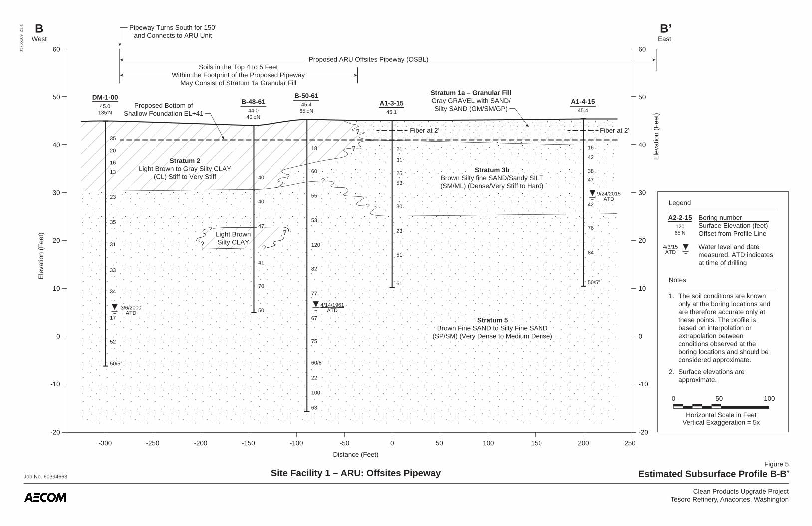
1. The soil conditions are known only at the boring locations and are therefore accurate only at these points. The profile is based on interpolation or extrapolation between conditions observed at the boring locations and should be considered approximate.
2. Surface elevations are approximate.
3. No groundwater was encountered in Borings A-1-15 or A1-2-15 at time of drilling.
4. Only selected structures called out.
Prop. Boiler Area
Elev. +53’ Working SurfaceElev. +53’ Working Surface
Proposed ARU FacilityOffsitesPipeway
+58 Finish Grade

Stratum 3a Olive Gray Silty CLAY to
Clayey SILT (CL/ML) (Medium Stiff to
Very Stiff)
Stratum 3a Olive Gray Silty CLAY to
Clayey SILT (CL/ML) (Medium Stiff to
Very Stiff)
Job No. 60394663
Figure 4
Estimated Subsurface Profile A2-A2’
3376
5169
_15.
ai
Clean Products Upgrade ProjectTesoro Refinery, Anacortes, Washington
A2West
A2’East
B-55-7065.0
35.0
40
30
24
18
23
108
1051
35.0
40
UT-2-1448.385’ S
+48.2
9
10
18
18
17
22
29
30
62
23
21
29
26
28
Elev. +53’ Working Surface
1
2
Stratum 2Brown Silty CLAY
(CL) (Stiff to Very Stiff)
Stratum 5Brown Fine SAND/Silty SAND
(SP/SM) (Medium Dense)
Stratum 3aBrown SILT
(ML) (Very Stiff)
9
A1-1-1558
90’ N
10
18
18
17
22
29
30
62
23
21
29
26
28
32
30
24
18
23
108
10512/31/70
ATD12/31/70
ATD
-250 -200 -150 -100 -50 0 50 100 150 250200 350300
Ele
vatio
n (F
eet) 40
50
20
10
30
60
70
Distance (Feet)
Site Facility 1 – ARU Unit
450400
40
50
20
10
30
60
70
Ele
vatio
n (F
eet)
4/3/15ATD
Horizontal Scale in FeetVertical Exaggeration = 5x
50 1000
Notes
1. The soil conditions are known only at the boring locations and are therefore accurate only at these points. The profile is based on interpolation or extrapolation between conditions observed at the boring locations and should be considered approximate.
2. Surface elevations are approximate.
3. Only selected structures called out.
Legend
Boring numberSurface Elevation (feet)Offset from Profile Line
Water level and date measuredATD indicates at time of drilling
A2-2-1548.385’S
??
????
??????
??
Two Prop.Columns
(26’ N, 52’ N)
Elev. +53’ Working Surface
1
2
ExistingGround
+58 Finish Grade
Approximate West Limitof Proposed Structures/Equipment
Prop. PDC(to North)
Prop. Pipeway
Proposed ARU Facility
20’
“C” St.25’ ±
W-2
624
Insi
de (
Eas
t) E
dge
“Int
erio
r R
oad”
INT
X
Pro
file
A-A
’
Stratum 2Brown Silty CLAY
(CL) (Stiff to Very Stiff)
Stratum 5Brown Fine SAND/Silty SAND
(SP/SM) (Medium Dense)
Stratum 3aBrown SILT
(ML) (Very Stiff)
Stratum 4Olive Gray to Dark Gray Silty CLAY/Sandy SILT
(CL/ML) (Very Stiff to Hard)
Stratum 4Olive Gray to Dark Gray Silty CLAY/Sandy SILT
(CL/ML) (Very Stiff to Hard)
Stratum 1a - Granular FillBrown Silty GRAVELwith Sand/Silty SAND
(GM/SM)
????
???? ??
??
??
3/6/2000ATD
4/14/1961ATD
9/24/2015ATD
Horizontal Scale in FeetVertical Exaggeration = 5x
50 1000
4/3/15ATD
Legend
Boring numberSurface Elevation (feet)Offset from Profile Line
Water level and date measured, ATD indicates at time of drilling
A2-2-1512065’N
Notes
1. The soil conditions are known only at the boring locations and are therefore accurate only at these points. The profile is based on interpolation or extrapolation between conditions observed at the boring locations and should be considered approximate.
2. Surface elevations are approximate.
3/6/2000ATD
4/14/1961ATD
9/24/2015ATD
Fiber at 2’Fiber at 2’35
20
16
13
23
35
31
33
34
17
52
50/5”
40
40
47
41
70
50
18
60
55
53
120
82
77
67
75
16
42
38
47
42
76
84
50/5”
?
?
?
?
??
??
?
Job No. 60394663
Figure 5
Estimated Subsurface Profile B-B’
3376
5169
_23.
ai
Clean Products Upgrade ProjectTesoro Refinery, Anacortes, Washington
Site Facility 1 – ARU: Offsites Pipeway
BWest
B’East
-50 0 50 100 150 200
Ele
vatio
n (F
eet)
20
30
00
-10
10
40
50
60
20
30
-10
10
40
50
60
Ele
vatio
n (F
eet)
Distance (Feet)
250-300 -250 -200 -150 -100
Proposed ARU Offsites Pipeway (OSBL)Soils in the Top 4 to 5 Feet
Within the Footprint of the Proposed PipewayMay Consist of Stratum 1a Granular Fill
Pipeway Turns South for 150’and Connects to ARU Unit
Proposed Bottom ofShallow Foundation EL+41
Fiber at 2’Fiber at 2’
DM-1-0045.0
135’N
35
20
16
13
23
35
31
33
34
17
52
50/5”
B-48-6144.0
40’±N
40
40
47
41
70
50
B-50-6145.4
65’±N
18
60
55
53
120
82
77
67
75
60/8”
22
100
63
60/8”
22
100
63
A1-3-1545.1
21
31
25
53
30
23
51
61
A1-4-1545.4
16
42
38
47
42
76
84
50/5”
-20-20
Stratum 3bBrown Silty fine SAND/Sandy SILT(SM/ML) (Dense/Very Stiff to Hard)
Stratum 5Brown Fine SAND to Silty Fine SAND
(SP/SM) (Very Dense to Medium Dense)
Stratum 3bBrown Silty fine SAND/Sandy SILT(SM/ML) (Dense/Very Stiff to Hard)
Stratum 2Light Brown to Gray Silty CLAY
(CL) Stiff to Very Stiff
Stratum 2Light Brown to Gray Silty CLAY
(CL) Stiff to Very Stiff
Light BrownSilty CLAYLight BrownSilty CLAY
Stratum 1a – Granular FillGray GRAVEL with SAND/Silty SAND (GM/SM/GP)
Stratum 5Brown Fine SAND to Silty Fine SAND
(SP/SM) (Very Dense to Medium Dense)
?
?
?
?
??
??
?

A2-5-15(PZ)128.9125’E
A2-5-15(PZ)128.9125’E
Job No. 60394663
Figure 6
Estimated Subsurface Profile C1-C1’
3376
5169
_16.
ai
Clean Products Upgrade ProjectTesoro Refinery, Anacortes, Washington
-100 0 100 200 300 400 500 600 700 900800 1,1001,000
Ele
vatio
n (F
eet)
80
90
60
50
70
100
110
130
120
80
90
60
50
70
100
110
120
130
Ele
vatio
n (F
eet)
C1North
C1’South
4/2/15ATD
4/3/15ATD
Stratum 3bBrown to Gray Silty fine SAND(SM) (Dense to Very Dense)
Stratum 4Dark Gray Silty CLAY/SILT
(CL/ML) (Hard)
4/2/15ATD
4/3/15ATD
A2-2-15119.5
Stratum 3bBrown to Gray Silty fine SAND(SM) (Dense to Very Dense)
Proposed Product TanksPad Elevation +111.5
Proposed Product TanksPad Elevation +111.5
Stratum 4Dark Gray Silty CLAY/SILT
(CL/ML) (Hard)
Stratum 4Dark Gray Silty CLAY/SILT
(CL/ML) (Hard)
Stratum 4Dark Gray Silty CLAY/SILT
(CL/ML) (Hard)
9
10
22
18
16
46
39
80
50/6"
50/6"
50/4"
50/5"
50/5"
50/5"
50/5"
50/4"
??
??
??
??
?
?
10
4
23
17
30
56
58
50
70
43
52
71
66
50/4"
75
87
?
?
?
?
?
??
??
??
??
?
10
4
23
17
30
56
58
50
70
43
52
71
66
50/4"
75
87
9
10
22
18
16
46
39
80
50/6"
50/6"
50/4"
50/5"
50/5"
50/5"
50/5"
50/4"
A2-1-15126.0
Distance (Feet)
Site Facility 2 – Product Tanks
NinthStreet
CL
Prop.Perimeter
RoadCL
ProposedContainment
Dike
ProposedContainment
Dike
Proposed Product Tank 285214’ Dia. x 60’ Tall
ProposedContainment
Dike
ProposedContainment
DikeProposed Product Tank 286
214’ Dia. x 60’ Tall
Proposed Tank 287152’ Dia. x 60’ Tall
Stratum 1a - Cohesive FillBrown Silty CLAY
(CL) (Medium Stiff to Stiff)
Stratum 1b - Cohesive FillBrown Silty CLAY
(CL) (Medium Stiff to Stiff)
1’ +/- Topsoil/SodExistingGround
Horizontal Scale in FeetVertical Exaggeration = 10x
100 2000
INTXProfile C2-C2’
A2-3-15(PZ)124.790’E
11/25/1511/25/15
INTXProfile C3-C3’
INTXProfile C3-C3’
Notes
1. See legend and notes on Figure 7.
2. Profile in vicinity of Tank 285 (north) and Tank 287 (south) based on interpolation between Borings A2-3-15/A2-4-15 and A2-5-15/A2-6-15, respectively (see Profiles C2-C2’ and C3-C3’).
Piezometer ScreenPiezometer ScreenPiezometer ScreenPiezometer Screen
39
21
34
21
51
32
39
50/3"
71
50/5"
88
87
67
71
45
50/5"
39
21
34
21
51
32
39
50/3"
71
50/5"
88
87
67
71
45
50/5"
SPT N-ValueSPT N-Value
11/25/1511/25/15
16
17
19
20
12
15
22
45
44
53
29
65
50/4"
50/4"
50/3"
50/5"
16
17
19
20
12
15
22
45
44
53
29
65
50/4"
50/4"
50/3"
50/5"
4/2/15ATD
9/22/15ATD
4/2/15ATD
9/23/15ATD
Stratum 2Brown Silty CLAY (CL) (Very Stiff to Stiff)
Stratum 2Brown Silty CLAY (CL) (Very Stiff to Stiff)

Stratum 2Brown Silty CLAY (CL)
(Very Stiff to Stiff)
Stratum 4Dark Gray Silty CLAY/SILT
(CL/ML) (Hard)
Stratum 4Dark Gray Silty CLAY/SILT
(CL/ML) (Hard)
Stratum 3bBrown to Gray Silty fine SAND(SM) (Dense to Very Dense)
Stratum 3bBrown to Gray Silty fine SAND(SM) (Dense to Very Dense)
Stratum 2Brown Silty CLAY (CL)
(Very Stiff to Stiff)
Stratum 1a - Cohesive FillBrown Silty CLAY
(CL) (Medium Stiff to Stiff)
Stratum 1b - Cohesive FillBrown Silty CLAY
(CL) (Medium Stiff to Stiff)
Job No. 60394663
Figure 7
Estimated Subsurface Profile C2-C2’
3376
5169
_21.
ai
Clean Products Upgrade ProjectTesoro Refinery, Anacortes, Washington
-50 0 50 100 150 200
Ele
vatio
n (F
eet)
80
90
60
50
70
100
110
130
120
80
90
60
50
70
100
110
120
1
2
130
Ele
vatio
n (F
eet)
C2West
C2’East
A2-4-15104.5
A2-3-15 (PZ)124.7
Distance (Feet)
250 300 350 400-150 -100
Site Facility 2 – Product Tanks
39
21
34
21
32
39
50/3"
71
50/5"
88
87
67
71
45
50/5"
23
34
55
39
40
55
24
47
65
74
80
See Inset
49
80
Piezometer Screen
39
21
34
21
32
39
50/3"
71
50/5"
88
87
67
71
45
50/5"
23
34
55
39
40
55
24
47
65
74
80
See Inset
49
80
50
40
62
78
76
50
40
62
78
76
Proposed Product TanksPad Elevation +111.5
Proposed Product TanksPad Elevation +111.5
Proposed Product Tank 285214’ Dia. x 60’ Tall
INTXProfile C1-C1’
ExistingGround
Piezometer Screen
4/2/15ATD
9/21/15ATD
4/2/15ATD
9/23/15ATD
“E” StreetCL
ProposedContainment
Dike
Prop.Perimeter
Access Road
Ditch
??
4/3/15ATD
Horizontal Scale in FeetVertical Exaggeration = 5x
50 1000
Legend
Boring numberSurface Elevation (feet)Offset from Profile Line
Water level and date measured, ATD indicates at time of drilling
A2-2-15120
125’E
Notes
1. The soil conditions are known only at the boring locations and are therefore accurate only at these points. The profile is based on interpolation or extrapolation between conditions observed at the boring locations and should be considered approximate.
2. Surface elevations are approximate.
5151
1
2
1
2
1
2
1
2
1
2
1
2
1
2
11/25/1511/25/15
“E” StreetCL
“E” StreetCL
Horizontal Scale in FeetVertical Exaggeration = 5x
50 1000
4/3/15ATD
Water level and date measured, ATD indicates at time of drilling
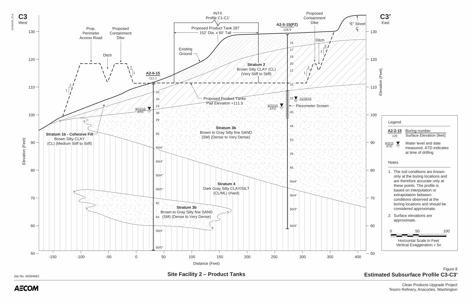
Notes
1. The soil conditions are known only at the boring locations and are therefore accurate only at these points. The profile is based on interpolation or extrapolation between conditions observed at the boring locations and should be considered approximate.
2. Surface elevations are approximate.
Legend
Boring numberSurface Elevation (feet)
A2-2-15120
Job No. 60394663
Figure 8
Estimated Subsurface Profile C3-C3’
3376
5169
_22.
ai
Clean Products Upgrade ProjectTesoro Refinery, Anacortes, Washington
A2-5-15(PZ)128.9
A2-6-15111.1
Site Facility 2 – Product Tanks
16
17
19
20
12
15
22
45
44
53
29
65
50/4"
50/4"
50/3"
50/5"
20
16
19
38
29
55
50/4"
50/4"
50/4"
50/5"
92
64
50/4"
50/5"
Piezometer Screen
Proposed Product Tank152’ Dia. x 60’ Tall
16
17
19
20
12
15
22
45
44
53
29
65
50/4"
50/4"
50/3"
50/5"
20
16
19
38
29
55
50/4"
50/4"
50/4"
50/5"??
?? ??
????
??
92
64
50/4"
50/5"
C3West
C3’East
-50 0 50 100 150 200
Ele
vatio
n (F
eet)
80
90
60
50
70
100
110
130
120
80
90
60
50
70
100
110
120
130
Ele
vatio
n (F
eet)
Distance (Feet)
250 300 350 400-150 -100
Piezometer Screen
1
2
1
2
1
2
1
2
ProposedContainment
Dike
ProposedContainment
Dike
Prop.Perimeter
Access Road
Ditch
DitchDitch
Proposed Product Tank 287152’ Dia. x 60’ Tall
INTXProfile C1-C1’
ExistingGround
Stratum 4Dark Gray Silty CLAY/SILT
(CL/ML) (Hard)
Stratum 4Dark Gray Silty CLAY/SILT
(CL/ML) (Hard)
Stratum 3bBrown to Gray Silty fine SAND(SM) (Dense to Very Dense)
Stratum 3bBrown to Gray Silty fine SAND(SM) (Dense to Very Dense)
Stratum 3bBrown to Gray Silty fine SAND(SM) (Dense to Very Dense)
Stratum 3bBrown to Gray Silty fine SAND(SM) (Dense to Very Dense)
Stratum 1a - Cohesive FillBrown Silty CLAY
(CL) (Medium Stiff to Stiff)
Stratum 1b - Cohesive FillBrown Silty CLAY
(CL) (Medium Stiff to Stiff)
4/2/15ATD
9/22/15ATD4/2/15
ATD9/22/15
ATD
Proposed Product TanksPad Elevation +111.5
Proposed Product TanksPad Elevation +111.5
Stratum 2Brown Silty CLAY (CL)
(Very Stiff to Stiff)
Stratum 2Brown Silty CLAY (CL)
(Very Stiff to Stiff)
11/25/1511/25/15

Job No. 60394663
Figure 9
Estimated Subsurface Profile D-D’
3376
5169
_17.ai
Clean Products Upgrade ProjectTesoro Refinery, Anacortes, Washington
Horizontal Scale in FeetVertical Exaggeration = 3x
30 600
20
30
40
50
60
70
Ele
vatio
n (F
eet)
20
30
40
50
60
70
Ele
vatio
n (F
eet)
DNorth
D’South
Note
1. The soil conditions are known only at the boring locations and are therefore accurate only at these points. The profile is based on interpolation or extrapolation between conditions observed at the boring locations and should be considered approximate.
Legend
Boring numberSurface elevation (feet)
Water level and date measured ATD indicates at time of drilling
B-53-7067.0 B24-06
66.0
Stratum 1a – Granular FillBrown Sandy GRAVEL/Fine SAND/Sandy SILT
(GP/SP/ML)
3/9/06ATD
B2466.0
SPT N-Value
48.0
35.0
Stratum 2Light Brown to Gray Silty CLAY
(CL) (Hard to Stiff)
Stratum 3bBrown to Gray Silty SAND/fine SAND
(SM/SP) (Dense to Very Dense)Occasional Lenses of SILT/CLAY
Stratum 4Olive Gray to Dark Gray Silty CLAY/Sandy SILT
(CL/ML) (Very Stiff to Hard)
Stratum 5Brown to Gray fine SAND/
silty SAND with Gravel(SP/SM) (Medium Dense to Very Dense)
3/9/06
12/30/70
44
55
53
99
200
130
130
235
175/8”
200/11”
18
27
85
67
54
69
50/5”
48.0
35.0
Stratum 2Light Brown to Gray Silty CLAY
(CL) (Hard to Stiff)
Stratum 3a Olive Gray Silty CLAY to Clayey SILT (CL/ML) (Medium Stiff to Very Stiff)
Stratum 3a Olive Gray Silty CLAY to Clayey SILT (CL/ML) (Medium Stiff to Very Stiff)
Stratum 3bBrown to Gray Silty SAND/fine SAND
(SM/SP) (Dense to Very Dense)Occasional Lenses of SILT/CLAY
Stratum 4Olive Gray to Dark Gray Silty CLAY/Sandy SILT
(CL/ML) (Very Stiff to Hard)
Stratum 5Brown to Gray fine SAND/
silty SAND with Gravel(SP/SM) (Medium Dense to Very Dense)
3/9/06ATD
12/30/70ATD
44
55
53
99
200
130
130
235
175/8”
200/11”
18
27
85
67
54
69
50/5”
???? ??
Site Facility 3 – ISOM UnitSite Facility 4 – NHT Revamp
9060300 120 150 180 210 240
Distance (Feet)
Seventh Street
Prop. Vessels(ISOM)(75’ E)
Prop. Vessels(ISOM)(90’ E)
Prop. NHT Reactor(10’ E)
2. Surface elevations are approximate.
3. Only selected structures called out.
INT
X
Pro
file
E-E
’
170

Prop. Column(65’ S)
Job No. 60394663
Figure 10
Estimated Subsurface Profile E-E’
3376
5169
_18.
ai
Clean Products Upgrade ProjectTesoro Refinery, Anacortes, Washington
20
10
30
40
50
60
70
Ele
vatio
n (F
eet)
20
10
30
40
50
60
70
80
Ele
vatio
n (F
eet)
EWest
E’East
B-53-7067.0
Stratum 1a – Granular FillBrown Sandy GRAVEL/
FINE SAND/SANDY SILT(GP/SP/ML)
SPT N-Value
48.0
44
55
53
99
170
200
130
130
235
175/8”
200/11”
Stratum 2Light Brown to Gray Silty CLAY
(CL) (Hard to Stiff)
Stratum 2Light Brown to Gray Silty CLAY
(CL) (Hard to Stiff)
Stratum 2Light Brown to Gray Silty CLAY
(CL) (Hard to Stiff)
Stratum 2Light Brown to Gray Silty CLAY
(CL) (Hard to Stiff)
Stratum 3bBrown to Gray Silty SAND/fine SAND
(SM/SP) (Dense to Very Dense)Occasional Lenses of
SILT/CLAY
Stratum 3bBrown to Gray Silty SAND/fine SAND
(SM/SP) (Dense to Very Dense)Occasional Lenses of
SILT/CLAY
Weathered Rock(Boulder?)
24
35
49
50/5”
52
50/4”
100/2”Weathered Rock
(Boulder?)Stratum 4
Olive Gray to Dark Gray Silty CLAY/Sandy SILT(CL/ML) (Very Stiff to Hard)
Stratum 4Olive Gray to Dark Gray Silty CLAY/Sandy SILT
(CL/ML) (Very Stiff to Hard)
Stratum 4Olive Gray to Dark Gray Silty CLAY/Sandy SILT
(CL/ML) (Very Stiff to Hard)
Stratum 4Olive Gray to Dark Gray Silty CLAY/Sandy SILT
(CL/ML) (Very Stiff to Hard)
Stratum 5Brown to Gray fine SAND/
silty SAND with Gravel(SP/SM) (Medium Dense to Very Dense)
Stratum 5Brown to Gray fine SAND/
Silty SAND with Gravel(SP/SM) (Medium Dense to Very Dense)
Stratum 5Brown to Gray fine SAND/
silty SAND with Gravel(SP/SM) (Medium Dense to Very Dense)
Stratum 5Brown to Gray fine SAND/
Silty SAND with Gravel(SP/SM) (Medium Dense to Very Dense)
48.0
44
B-3-9374.030’N
28
34
26
18
28
B-2-9365.2±55’N
A3-1-1564.858’S
A3-2-1564.968’S
24
35
49
50/5”
52
50/4”
100/2”
SPBrown SAND,
Some Silt
ApproximateGround Surfaceat PDC (Beyond) 44
56
74
50/6”
50/6”
SPBrown SAND,
Some Silt
ApproximateGround Surfaceat PDC (Beyond)
ML/SM
MLGrayish Brown Streaks of
Orange Sandy SILT, Some Gravel
URS-1-0081.030’S
18
47
15
30
44
56
74
50/6”
50/6”
18
34
26
18
55
53
99
170
200
130
130
235
175/8”
200/11”
????
??
??
Site Facility 3 – ISOM UnitSite Facility 4 – NHT Revamp
??
??
??
Prop. Vessels(40’-75’ S)D Street
Prop. Equipment(80’ N to 20’ S)90’ to
Boring B-55-70(See Figure 4)
Prop. NHT Reactor(20’ S)
NHT Facility(Varies)
ISOM Facility(Varies)
Pipeway Street
1.5
1Prop. PDC
(110’ N)ApproximateExistingGround
Stratum 3a Olive Gray Silty CLAY to
Clayey SILT (CL/ML) (Medium Stiff to
Very Stiff)
Stratum 3a Olive Gray Silty CLAY to
Clayey SILT (CL/ML) (Medium Stiff to
Very Stiff)
??????
-80-120-160-200 -40 0 40 80 120 160 200 240 280 320
Distance (Feet)
INT
X
Pro
file
D-D
’
??
Note: Boring B-2-93 shown for reference only. Profile does not reflect stratum transitions at B-2-93.
Stratum 1a - Cohesive FillBrown Silty CLAY
(CL) (Medium Stiff to Stiff)
Stratum 1b - Cohesive FillBrown Silty CLAY
(CL) (Medium Stiff to Stiff)
12/30/70ATD
12/16/93ATD
14 8
9
10
12
17
23
46
30
45
44
52
10
14
18
25
20
38
49
40
64
47
32
50/4”
12/30/70ATD
12/16/93ATD
14 8
9
10
12
17
23
46
30
45
44
52
10
14
18
25
20
38
49
40
64
47
32
50/4”
Note
1. See legend and notes on Figure 9.Horizontal Scale in Feet
Vertical Exaggeration = 4x
40 800
Ground Surface May NotReflect Current Grades
Approx. Proposed VCU Skid (5’ West)
Approx.Proposed VCS
Approx. Proposed VCB (50’ West)
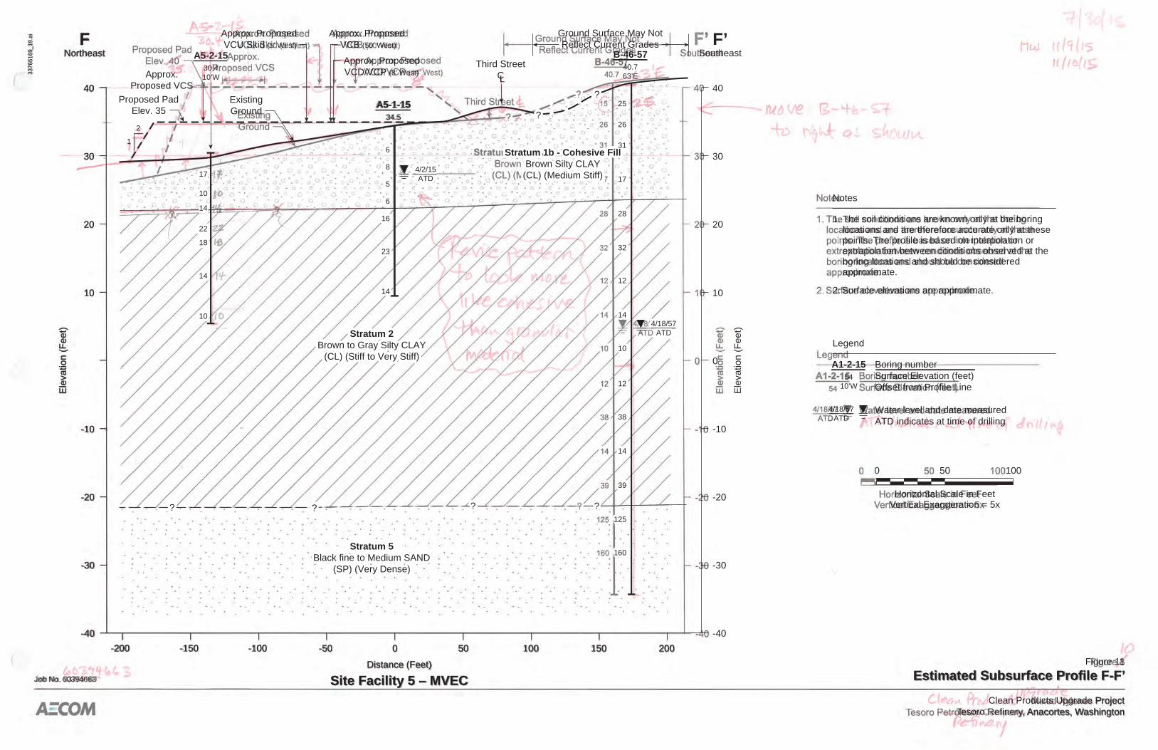
Job No. 60394663
Figure 11
Estimated Subsurface Profile F-F’
3376
5169
_19.
ai
Clean Products Upgrade ProjectTesoro Refinery, Anacortes, Washington
Horizontal Scale in FeetVertical Exaggeration = 5x
50 1000
-40
-50-100-150-200 0 50 100 150 200
-30
-20
-10
10
Ele
vatio
n (F
eet)
-40
-30
-20
-10
0
10
20
30
20
30
4040
Ele
vatio
n (F
eet)
FNortheast
F’Southeast
Notes
1.
2. Surface elevations are approximate.
The soil conditions are known only at the boring locations and are therefore accurate only at these points. The profile is based on interpolation or extrapolation between conditions observed at the boring locations and should be considered approximate.
Legend
Boring numberSurface Elevation (feet)Offset from Profile Line
Water level and date measuredATD indicates at time of drilling
A1-2-1554
10’W
Stratum 2Brown to Gray Silty CLAY
(CL) (Stiff to Very Stiff)
Stratum 5Black fine to Medium SAND
(SP) (Very Dense)
? ??
?
Stratum 1b - Cohesive FillBrown Silty CLAY(CL) (Medium Stiff)
6
8
5
6
16
23
14
15
26
31
17
28
32
12
14
10
12
38
14
39
125
160
4/18/57ATD
4/2/15ATD
Stratum 2Brown to Gray Silty CLAY
(CL) (Stiff to Very Stiff)
Stratum 5Black fine to Medium SAND
(SP) (Very Dense)
??? ??
?
Stratum 1b - Cohesive FillBrown Silty CLAY(CL) (Medium Stiff)
A5-1-1534.5
6
17
10
14
22
18
14
10
17
10
14
22
18
14
10
8
5
6
16
23
14
A5-2-1530.410’W
B-46-5740.763’E
25
26
31
17
28
32
12
14
10
12
38
14
39
125
160
4/18/57ATD
4/18/57ATD
4/2/15ATD
Approx. ProposedVCD/VCP (8’ West)
Distance (Feet)
Site Facility 5 – MVEC
ExistingGround
Proposed PadElev. 35 ??
Third StreetCL
1
2


