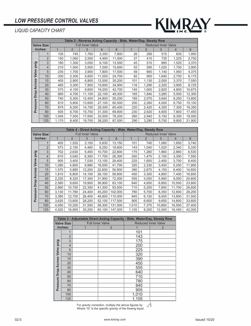
www.kimray.com LOW PRESSURE CONTROL VALVES REVERSE ACTING MODEL RA All Pictures shown are for illustration purpose only. Actual product may vary due to product enhancement. Standard Configuration Code † Order Code Line Size Connection Type Inner Valve Size Max. W.P. †† psig Cv Cf BRA1SADFS EUA 1" NPT 1" 300 13.2 0.74 BRA1SADRS EUA1 1/2" 5.0 0.75 BRA2SADFS EUB 2" NPT 2" 300 47.0 0.84 BRA2ARDFS EUC 150RF 250 BRA2SADRS EUB1 NPT 1 1/4" 300 21.0 0.75 BRA2ARDRS EUC1 150RF 250 BRA3SADFS EUE 3" NPT 3" 300 117 0.75 BRA3ARDFS EUF 150RF 250 BRA3SADRS EUE1 NPT 1 5/8" 300 34.0 0.82 BRA3ARDRS EUF1 150RF 250 BRA4SADFS EUG 4" NPT 4" 300 210 0.75 BRA4ARDFS EUH 150RF 250 BRA4SADRS EUG1 NPT 2" 300 55.0 0.80 BRA4ARDRS EUH1 150RF 250 BRA4ARDFS EUI 6" 150RF 6" 250 480 0.75 BRA4ARDRS EUI1 150RF 3" 250 120 0.80 NOTES: For standard & optional seals, metals, Cf Cv values, material specifications & dimensions see technical data on pages 02:I - 02:VI † For Corrosive service remove last "S" & replace with "C" † For KimCoat option remove last "S" & replace with "K" † For code builder see page 03:00.2 †† Max W.P. values based on -20°F to 100°F. APPLICATIONS: Any system requiring a valve to close when it receives a pneumatic signal. FEATURES: Tight shut-off Single soft seat Removable valve seat Minimum maintenance All internal parts can be removed with valve in-line Full line size opening: Ratio of diaphragm to seat area is 2:1 Reduced opening: Ratio of diaphragm to seat area is: 8:1 on 1" & 5:1 on 2", 3", 4", and 6" CERTIFICATIONS: Canadian Registration Number (CRN): 0C15737.24567890NTY (Ductile) 0C15620.24567890NTY (Steel) Kimray is an ISO 9001- certified manufacturer. Oil 1/4" FNPT Stem Assembly Diaphragm Pressure Upstream Pressure Downstream Pressure Issued 10/20 02:10.1
Transcript
www.kimray.com
LOW PRESSURE CONTROL VALVESREVERSE ACTING
MODEL RA
All Pictures shown are for illustration purpose only. Actual product may vary due to product enhancement.
Standard Configuration Code †
Order Code
Line Size
Connection Type
Inner Valve Size
Max. W.P. †† psig Cv Cf
BRA1SADFS EUA1" NPT
1"300
13.2 0.74
BRA1SADRS EUA1 1/2" 5.0 0.75
BRA2SADFS EUB
2"
NPT2"
30047.0 0.84
BRA2ARDFS EUC 150RF 250
BRA2SADRS EUB1 NPT1 1/4"
30021.0 0.75
BRA2ARDRS EUC1 150RF 250
BRA3SADFS EUE
3"
NPT3"
300117 0.75
BRA3ARDFS EUF 150RF 250
BRA3SADRS EUE1 NPT1 5/8"
30034.0 0.82
BRA3ARDRS EUF1 150RF 250
BRA4SADFS EUG
4"
NPT4"
300210 0.75
BRA4ARDFS EUH 150RF 250
BRA4SADRS EUG1 NPT2"
30055.0 0.80
BRA4ARDRS EUH1 150RF 250
BRA4ARDFS EUI6"
150RF 6" 250 480 0.75
BRA4ARDRS EUI1 150RF 3" 250 120 0.80
NOTES:For standard & optional seals, metals, Cf Cv values, material specifications & dimensions see technical data on pages 02:I - 02:VI† For Corrosive service remove last "S" & replace with "C"† For KimCoat option remove last "S" & replace with "K"† For code builder see page 03:00.2†† Max W.P. values based on -20°F to 100°F.
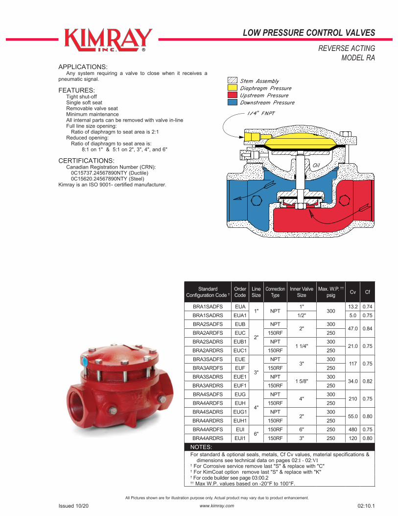
APPLICATIONS: Any system requiring a valve to close when it receives a pneumatic signal.
FEATURES: Tight shut-off Single soft seat Removable valve seat Minimum maintenance All internal parts can be removed with valve in-line Full line size opening: Ratio of diaphragm to seat area is 2:1 Reduced opening: Ratio of diaphragm to seat area is: 8:1 on 1" & 5:1 on 2", 3", 4", and 6"
CERTIFICATIONS: Canadian Registration Number (CRN): 0C15737.24567890NTY (Ductile) 0C15620.24567890NTY (Steel)Kimray is an ISO 9001- certified manufacturer.
20 Optional Spring for Fail Open 1358 1388 7132 1529 1575 1358IL 1388 7132 1529 1575 * These parts are recommended spare parts and are stocked as repair kits. ‡ Coated Parts available with "K" service type
Repair Kits Full Port RCM RDL RDM RDN RDO RCMHSN RDLHSN RDMHSN RDNHSN RDOHSNReduced Port RDB RNI RNJ RNK RNL RDBHSN RNIHSN RNJHSN RNKHSN RNLHSN
*
*
*
*
*
*
*
*
02:10.2 Issued 7/21
www.kimray.com
LOW PRESSURE CONTROL VALVESFLOW COEFFICIENT
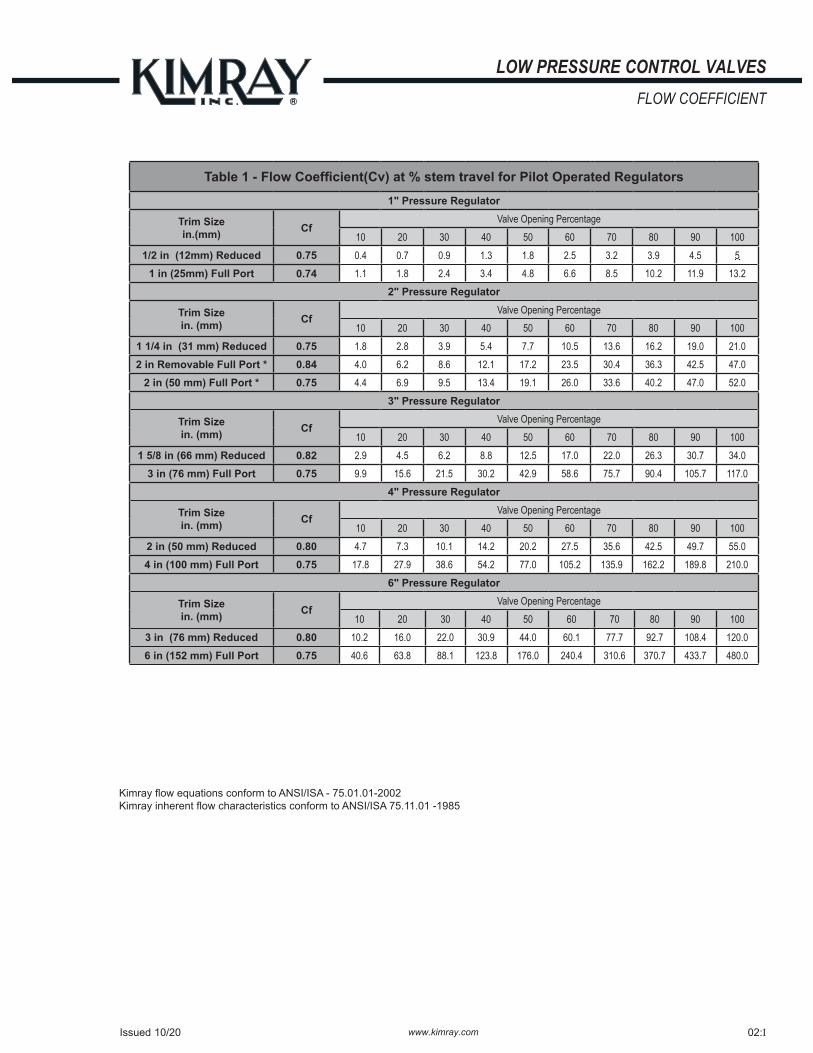
Table 1 - Flow Coefficient(Cv) at % stem travel for Pilot Operated Regulators


![Welcome [] · Public Open House. Bridge MP 370.7 Pier Replacement Project Figure. 1 N e n a n a R i v e r N e n a n a R i v e r a a a 28 27 33 34 ARRC Bridge at Ferry (BR 370.7) Contractor](https://static.documents.pub/doc/80x56/5f9a19e805206c28a0285462/welcome-public-open-house-bridge-mp-3707-pier-replacement-project-figure.jpg)


