August 2018 IEEE P802. 15-18-0388-00-004x Submission Page 1 Matt Gillmore, Itron IEEE P802.15 Wireless Personal Area Networks Project Task Group 4x FANE Title Coexistence Assurance Document-802.15.4x FANE Date Submitted August 6, 2018 Source Matt Gillmore Itron Voice: E-mail: [email protected]Re: Coexistence Assurance Document Abstract Purpose Define Coexistence Requirements Notice This document has been prepared to assist the IEEE P802.15. It is offered as a basis for discussion and is not binding on the contributing individual(s) or organization(s). The material in this document is subject to change in form and content after further study. The contributor(s) reserve(s) the right to add, amend or withdraw material contained herein. Release The contributor acknowledges and accepts that this contribution becomes the property of IEEE and may be made publicly available by P802.15.
Transcript
August 2018 IEEE P802. 15-18-0388-00-004x
Submission Page 1 Matt Gillmore, Itron
IEEE P802.15
Wireless Personal Area Networks
Project Task Group 4x FANE
Title Coexistence Assurance Document-802.15.4x FANE
Notice This document has been prepared to assist the IEEE P802.15. It is offered as a basis for discussion and is not binding on the contributing individual(s) or organization(s). The material in this document is subject to change in form and content after further study. The contributor(s) reserve(s) the right to add, amend or withdraw material contained herein.
Release The contributor acknowledges and accepts that this contribution becomes the property of IEEE and may be made publicly available by P802.15.
August 2018 IEEE P802. 15-18-0388-00-004x
Submission Page 2 Matt Gillmore, Itron
There were no changes made to the SUN PHYs (15.4g) as a result of work on this
project, therefore the Coexistence Assurance Document passed in April of 2011
remains the operative document. A copy is included here for reference.
April 2011 IEEE 802.15-10-0668-05-004g
IEEE P802.15
Wireless Personal Area Networks
Project IEEE P802.15 Working Group for Wireless Personal Area Networks (WPANs)
Title TG4g Coexistence Assurance Document
Date Submitted April 2011
Source [Chin-Sean Sum] [NICT, Japan] *List of co-authors in the
Abstract Analysis on coexistence of 802.15.4g with other 802 systems within the same spectrum bands
Purpose To address the coexistence capability of 802.15.4g
Notice This document has been prepared to assist the IEEE P802.15. It is offered as a basis for discussion and is not binding on the contributing individual(s) or organization(s). The material in this document is subject to change in form and content after further study. The contributor(s) reserve(s) the right to add, amend or withdraw material contained herein.
Release The contributor acknowledges and accepts that this contribution becomes the property of IEEE and may be made publicly available by P802.15.
1
April 2011 IEEE 802.15-10-0668-05-004g
Contributors of the CA document are sorted by alphabetical order of the last name: Afshin Amini Phil Beecher James P.K. “Trainwreck” Gilb Hiroshi Harada Fumihide Kojima Clinton Powell Benjamin A. Rolfe Chin-Sean Sum Khurram Waheed 1. Introduction 1.1. Bibliography [B1] IEEE Std. 802.15.1TM – 2005, IEEE Standard for Information Technology – Telecommunications and Information exchange between systems – Local and metropolitan area networks – Specific requirements – Part 15.1: Wireless Medium Access Control (MAC) and Physical Layer (PHY) Specifications for Wireless Personal Area Networks (WPANs). [B2] IEEE Std. 802.15.2TM – 2003, IEEE Recommended Practice for Information Technology – Telecommunications and Information exchange between systems – Local and metropolitan area networks – Specific requirements – Part 15.2: Coexistence of Wireless Personal Area Networks with Other Wireless Devices Operating in Unlicensed Frequency Bands. [B3] IEEE Std. 802.15.3TM – 2003, IEEE Standard for Information Technology – Telecommunications and Information exchange between systems – Local and metropolitan area networks – Specific requirements – Part 15.3: Wireless Medium Access Control (MAC) and Physical Layer (PHY) Specifications for High Rate Wireless Personal Area Networks (WPANs). [B4] IEEE Std. 802.15.4TM – 2006, IEEE Standard for Information Technology – Telecommunications and Information exchange between systems – Local and metropolitan area networks – Specific requirements – Part 15.4: Wireless Medium Access Control (MAC) and Physical Layer (PHY) Specifications for Low-Rate Wireless Personal Area Networks (WPANs). [B5] IEEE Std. 802.11TM – 2007, IEEE Standard for Information Technology –
2
April 2011 IEEE 802.15-10-0668-05-004g
Telecommunications and Information exchange between systems – Local and metropolitan area networks – Specific requirements – Part 11: Wireless LAN Medium Access Control (MAC) and Physical Layer (PHY) Specifications. [B6] IEEE Std. 802.15.4g /D1 – 2010, IEEE Draft Standard for Information Technology – Telecommunications and Information exchange between systems – Local and metropolitan area networks – Specific requirements – Part 15.4: Wireless Medium Access Control (MAC) and Physical Layer (PHY) Specifications for Low-Rate Wireless Personal Area Networks (WPANs) – Amendment 4: Physical Layer Specifications for Low Data Rate Wireless Smart Metering Utility Networks. [B7] IEEE Std. 802.11nTM, IEEE Standard for Information Technology - Telecommunications and Information exchange between systems - Local and metropolitan area networks - Specific requirements - Part 11: Wireless LAN Medium Access Control (MAC) and Physical Layer (PHY) Specifications - Amendment 5: Enhancements for Higher Throughput. 1.2. Acronyms ASK amplitude shift keying AWGN additive white Gaussian noise BER bit error rate BPSK binary phase shift keying Coex-beacon coexistence beacon CA coexistence assurance CAP contention access period CCI co-channel interference CCK complementary code keying CFP contention free period CSM common signaling mode CSMA/CA collision avoidance multiple access / collision avoidance D-QPSK differential quadrature phase shift keying DSSS direct sequence spread spectrum DUR desired to undesired ratio ED energy detection FER frame error rate FFD full function device FHSS frequency hopping spread spectrum
3
April 2011 IEEE 802.15-10-0668-05-004g
GFSK Gaussian frequency shift keying GTS guaranteed time slot LQI link quality indicator MAC medium access control MPM multi-PHY management MR-FSK multi-rate and multi-regional frequency shift keying MR-OFDM multi-rate and multi-regional orthogonal frequency division
multiplexing MR-O-QPSK multi-rate and multi-regional offset-quadrature phase shift keying PAN personal area network PHY physical OFDM orthogonal frequency division multiplexing O-QPSK offset-quadrature phase shift keying PSSS parallel sequence spread spectrum QAM quadrature amplitude modulation RF radio frequency RFD reduced function device SC single carrier SFD start frame delimiter SHR synchronization header SINR signal to interference and noise ratio SIR signal to noise ratio SOI sphere of influence SUN smart utility network TDMA time division multiple access 2. Overview 2.1. Overview of IEEE 802.15.4g The IEEE 802.15 Task Group 4g defines PHY amendment and related MAC extensions based on 802.15.4 for wireless Smart Utility Networks (SUN). The objective of the standard is to provide a global standard that facilitates very large scale process control applications such as the utility smart-grid network capable of supporting large, geographically diverse networks with minimal infrastructure, with potentially millions of fixed endpoints.
4
April 2011 IEEE 802.15-10-0668-05-004g
An 802.15.4g network contains one centralized coordinator. The coordinator starts and manages the network to facilitate communications among network devices. A network consists of one coordinator and at least one network device. In the 802.15.4g, there are two types of devices, the FFD and the RFD. The FFD contains the complete set of MAC services and is capable of acting as either a coordinator or a network device. The RFD contains reduced set of MAC services and is only capable as a network device. For medium accessing, the devices employ CSMA/CA to avoid wasteful collisions. Alternatively, TDMA may also be employed for guaranteed transmissions. This standard specifies a total of three PHYs, namely the MR-FSK, MR-OFDM and MR-O-QPSK. All the PHYs are specified to address different system demands and market segments. In order to avoid mutual interference caused by multiple PHYs operating in the same location, an MPM scheme is defined to coordinate among the potentially coexisting PHYs. Each PHY is specified to allocate a fraction of regulated spectrum bands out of the complete list shown in the following sub-clause. 2.2. Regulatory Information The allocated frequency bands for the 802.15.4g are given as below: (a) 2400-2483.5 MHz (Worldwide) (b) 902-928 MHz (United States) (c) 863-870 MHz (Europe) (d) 950-958 MHz (Japan) (e) 779-787 MHz (China) (f) 1427-1518 MHz (United States, Canada) (g) 450-470 MHz (United States) (h) 896-901 MHz (United States) (i) 901-902 MHz (United States) (j) 928-960 MHz (United States) (k) 470-510 MHz (China) (l) 917-923.5 MHz (Korea) Out of the list, bands (a)-(e) and (k) are occupied by more than one 802.15.4g PHY, while bands (f)-(j) and (l) are only occupied by a single PHY. The details are listed in the Table 1.
5
April 2011 IEEE 802.15-10-0668-05-004g
Table 1 Regulatory Domains for Respective PHYs Specified in 802.15.4g
Frequency Band IEEE 802.15.4g PHYs
MR-FSK MR-O-QPSK MR-OFDM
2400-2483.5 MHz (Worldwide) X X X
902-928 MHz (United States) X X X
863-870 MHz (Europe) X X X
950-958 MHz (Japan) X X X
779-787 MHz (China) X X
1427-1518 MHz (United States, Canada)
X
450-470 MHz (United States) X
896-901 MHz (United States) X
901-902 MHz (United States) X
928-960 MHz (United States) X
470-510 MHz (China) X X X
917-923.5 MHz (Korea) X
2.3. Overview of Coexistence Mechanism in 802.15.4 and 802.15.4g The importance of coexistence mechanism in the SUN is two-fold. Internally, the SUN specified three alternative PHYs and these PHYs shall be able to coexist with each other if operating co-locatedly in the same frequency band. Externally, the SUN has to share multiple frequency bands with dissimilar 802 systems. The following sub-clauses describe the coexistence mechanism specified in the 802.15.4 and 802.15.4g, that facilitates both homogeneous (among different SUN PHYs) and heterogeneous (across other 802 systems) coexistence. 2.3.1. MPM scheme The MPM scheme is a newly defined mechanism in the 802.15.4g. The motivation of defining the MPM is the specification of multiple alternative SUN PHYs potentially operating in the same frequency bands. The sole objective of MPM is to facilitate CCI avoidance when more than one PHY are occupying the same channel. The description
6
April 2011 IEEE 802.15-10-0668-05-004g
of MPM can be found in sub-clause 5.2b [B6]. To facilitate the MPM operation, a pre-defined common PHY mode known as the CSM, a new frame known as the coex-beacon, and several corresponding MAC functions are specified. Coordinators of all three PHYs that operate at duty cycle greater than 1% shall be able to transmit and receive the CSM. The basic operation of the MPM is to require the coordinators to scan for the coex-beacon in CSM. Upon receiving a coex-beacon, the incoming coordinator realizes that there is another network occupying the channel, and may take several measures to avoid CCI, such as trying another channel or achieving synchronization with the current network. On the other hand, while operating in a certain channel, a coordinator is also required to send out coex-beacon in CSM to alert possible incoming coordinators. 2.3.2. Common Signaling Mode (CSM) The CSM is a pre-defined common PHY mode that has to be supported by all the specified PHYs in 802.15.4g. CSM is used to aid coexistence among the alternative SUN PHYs. The role of the CSM is coexistence is primarily two-fold: (a) to facilitate the MPM mechanism that targets interference avoidance among networks with different PHYs, and (b) to enable a more efficient detection scheme (e.g. scanning, CCA, and etc.) between networks with different PHY designs. The PHY layer specification of the CSM is given in 6.1a [B6]. 2.3.3. Channel Scan A channel scan is an act of a receiver to detect any signal present in the channel. The channel scan is the basic means for systems to coexist: enabling detection between networks. There are different types of channel scan that give different levels of accuracy and require different levels of radio resources. In the 802.15.4g, the specified channel scan types are ED channel scan, active channel scan, passive channel scan and enhanced CMS channel scan. The following sub-clauses provide the details of the available scan types in the 802.15.4 and 802.15.4g. The ED scan, active channel scan and passive channel scan are specified in 802.15.4, while the enhanced CMS channel scan is newly specified in 802.15.4g.
7
April 2011 IEEE 802.15-10-0668-05-004g
2.3.3.1. ED Channel Scan The ED channel scan allows a device to obtain a measure of the peak energy of the RF signal on the channel it is operating. The ED scan could be used by a prospective PAN coordinator to select a channel on which to operate prior to starting a new PAN. Upon detecting an existing PAN in a specific channel, incoming PAN coordinator may avoid colliding with the existing network by switching to another channel, thus enabling coexistence. The details of ED channel scan are given in 7.5.2.1.1 [B4]. 2.3.3.2. Enhanced CSM Channel Scan The enhanced CSM channel scan is newly defined in 802.15.4g, where three alternative PHYs are specified. A common signaling format, namely the CSM, is a PHY mode that has to be supported by all coordinators. Besides the coordinators, all devices may also support the CSM. The enhanced CSM channel scan allows a device to perform the specific sequence detection of the CSM, which is significantly more accurate as compared to energy detection. In cases where a device, the same goes to any device in the other non-SUN systems, is capable of receiving the CSM, the enhanced CSM channel scan can be performed for a more efficient coexistence. 2.3.3.3. Active Channel Scan An active scan allows a device to locate any coordinator transmitting beacon frames within its radio SOI. This could be used by a prospective PAN coordinator to select a PAN identifier prior to starting a new PAN, or it could be used by a device prior to association. In a logical channel, the device first sends a beacon request command to the possibly existing coordinator. If the coordinator exists, and is operating in a non-beacon-enabled mode, it will send the beacon in the using the CSMA protocol. If the coordinator is operating in a beacon-enabled mode, it will send the beacon in the next scheduled beacon interval. Besides the intended SUN devices, other non-SUN devices may also employ the active channel scan and ED scan in order to detect and avoid possible scenarios of interference. Additionally, if the CSM is supported, CSM scan can be performed for increased detection probability. The details of active channel scan are given in 7.5.2.1.2 [B4].
8
April 2011 IEEE 802.15-10-0668-05-004g
2.3.3.4. Passive Channel Scan A passive scan, like an active scan, allows a device to locate any coordinator transmitting beacon frames within its radio SOI. One major difference in the passive channel scan is that the beacon request command is not transmitted by the devices. This scan is used to search for coordinators in the radio SOI, participating in the beacon-enabled mode. An existing coordinator, will send periodical beacons and incoming devices will be performing passive scan to receive the beacon. In a similar way, other non-SUN devices may also employ the passive channel scan and ED scan in order to detect and avoid possible scenarios of interference. Additionally, if the CSM is supported, CSM scan can be performed for increased detection probability. The details of passive channel scan are given in 7.5.2.1.3 [B4]. 2.3.4. Clear Channel Assessment For the non-beacon-enabled network and CAP in the beacon-enabled network, the CSMA/CA mechanism is specified for handling multiple channel access. In the CSMA/CA mechanism, before transmissions of frames, CCA has to be performed to determine the vacancy of the channel. At least one of the following three CCA methods has to be performed in the CCA: ED over a certain threshold, detection of an 802.15.4g signal (e.g. the CSM), or a combination of these methods. Non-SUN devices may participate in the CSMA/CA protocol in a SUN system if it supports any of the CCA methods, so to avoid CCI with co-locating devices. The details of CCA are given in 6.9.9 [B4]. 2.3.5. LQI and ED The LQI measurement is a characterization of the strength and/or quality of a received frame. The measurement may be one of the receiver ED, the SNR estimation, or a combination of both. An example of conducting an LQI evaluation is by using the ED and SNR measurements. Low ED and low SNR values indicate that the receive signal is weak, possibly due to a bad channel or obstruction. High ED and low SNR values indicate that interference in the channel is present. High ED and high SNR naturally mean that the channel is in good condition. By using the LQI-ED-duet, the factors causing a degraded performance can be determined, or at least estimated, with which, responsive actions can be taken to rectify the situation. The details on ED and LQI are given in 6.9.7 and 6.9.8 [B4].
9
April 2011 IEEE 802.15-10-0668-05-004g
2.3.6. Channel Switching Channel switching can be performed by a coordinator to avoid a channel with degraded quality due to interference or other factors. Upon determining that the channel quality is degraded (e.g. through LQI measurement), a coordinator may cease current transmissions, perform channel scan to find another channel with better quality to be switched to. The capability of channel switching equips the SUN to be able to coexist with other system, even in cases where the signal characteristics of the co-located network cannot be recognized. 2.3.7. Neighbor Network Capability Neighbor network capability is a scheme facilitating coexistence and interoperability among multiple PHYs in the SUN, as well as between the SUN and other dissimilar systems. In the beacon-enabled network, GTS can be allocated by the coordinator to a particular device to perform guaranteed transmission within the CFP employing the TDMA protocol. Similarly, a device belonging to a dissimilar system that supports the GTS allocation and management protocol can request and obtain GTS in the CFP to perform local communications. In this manner, the dissimilar system is able to form a neighbor network that could achieve synchronization with the existing SUN. The GTS allocation and management protocol is detailed in 7.5.7 [B4]. Besides the CFP, inactive portion is also specified in a superframe for the purpose of power saving. The timing information of the active and inactive boundaries is given in the beacon frame. A dissimilar system can take advantage to occupy the inactive portions of the superframe for local communications. The condition for achieving this level of synchronization is the ability to receive and decode the information contained in the SUN beacon frame. The details of the active and inactive portions are given in 7.5.1.1 [B4]. 2.3.8. Duty Cycle Duty cycle is known as the proportion of the signal duration to the regular interval or period of time. A part of devices specified in 802.15.4g SUN, primarily the
10
April 2011 IEEE 802.15-10-0668-05-004g
battery-powered devices operate in a very low duty cycle. While typical network device may operate at duty cycle as low as below 1%, the coordinators may operate at duty cycle of around 10%, as described in E5.4 [B4]. These low duty cycle devices only transmit energy into the air in a short duration in a long interval, and are less likely to cause interference to other co-located networks. 2.3.9. SFD Detection The SFD is a field indicating the end of the SHR and the start of the frame data. The function of SFD is to determine the timing boundary from which point the receiver extracts the data in the frame. In 802.15.4g, besides timing establishment, SFD is also designed to facilitate the devices to distinguish the standard specification to which the incoming signal is belonging. The SFD detection is employed for differentiating 802.15.4g frame from the 802.15.4d frame. 3. Dissimilar Systems Sharing the Same Frequency Bands with 802.15.4g This clause presents an overview on other 802 systems which occupy the same frequency bands that are also specified for the 802.15.4g. The following sub-clauses present co-locating dissimilar systems with reference to respective frequency bands. The frequency bands of interest are the 2400-2483.5 MHz band, the 902-928 MHz band, the 863-870 MHz band, the 950-958 MHz band, the 779-787 MHz band and the 400-430 MHz band. Each frequency band is discussed referring to a table listing all the coexisting systems from other standard specifications. The contents of the tables (in this and the next sub-clause) are formatted as below:
(a) Standard specification: the name of the 802 system with which 802.15.4g system is coexisting
(b) PHY specification: the PHY design of the above 802 system specification (c) Receiver bandwidth: the receiver bandwidth of the above 802 system
specification (d) Transmit power: the transmit power of the above 802 system specification (e) Receiver sensitivity: the receiver sensitivity of the above 802 system
specification. (f) Involved 802.15.4g system: the particular PHY in 802.15.4g that is coexisting
11
April 2011 IEEE 802.15-10-0668-05-004g
with the above 802 system specification Note: The data rate modes including receiver bandwidth, transmit power and receiver sensitivity listed in the columns of the following tables are only a part of the complete list from the respective standard specifications. These data rate modes are chosen for the purpose of coexistence analysis in this CA document. 3.1. Coexisting Systems in 2400-2483.5 MHz Band (Worldwide) Table 2 shows the list of other 802 systems that are sharing the 2400-2483.5 MHz band with the MR-FSK, MR-O-QPSK and MR-OFDM PHYs in 802.15.4g.
Table 2: Dissimilar Systems Coexisting with 802.15.4g Systems within the
2400-2483.5 MHz Band
System PHY Specification Involved 802.15.4g System
802.11b DSSS CCK
MR-FSK, MR-O-QPSK, MR-OFDM
802.11g OFDM BPSK
802.11n OFDM QPSK
802.15.1 FHSS GFSK
802.15.3 SC D-QPSK
802.15.4 DSSS O-QPSK
12
April 2011 IEEE 802.15-10-0668-05-004g
3.2. Coexisting Systems in 902-928 MHz Band (United States) Table 3 shows the list of other 802 systems that are sharing the 902-928 MHz band with the MR-FSK, MR-O-QPSK and MR-OFDM PHYs in 802.15.4g.
Table 3 : Dissimilar Systems Coexisting with 802.15.4g Systems within the 902-928 MHz Band
System PHY Specification Involved 802.15.4g System
802.15.4
DSSS BPSK
MR-FSK, MR-O-QPSK, MR-OFDM
DSSS O-QPSK
PSSS ASK
802.15.4c DSSS BPSK
802.11ah Currently in progress, specification not available
3.3. Coexisting Systems in 863-870 MHz Band (Europe) Table 4 shows the list of other 802 systems that are sharing the 863-870 MHz band with the MR-FSK, MR-O-QPSK and MR-OFDM PHYs in 802.15.4g.
Table 4: Dissimilar Systems Coexisting with 802.15.4g Systems within the 863-870 MHz Band
System PHY Specification Involved 802.15.4g System
802.15.4
DSSS BPSK
MR-FSK, MR-O-QPSK, MR-OFDM
DSSS O-QPSK
PSSS ASK
802.15.4c DSSS BPSK
13
April 2011 IEEE 802.15-10-0668-05-004g
3.4. Coexisting Systems in 950-958 MHz Band (Japan) Table 5 shows the list of other 802 systems that are sharing the 950-958 MHz band with the MR-FSK PHY in 802.15.4g.
Table 5: Dissimilar Systems Coexisting with 802.15.4g Systems within the 950-958 MHz Band
System PHY Specification Involved 802.15.4g System
802.15.4d DSSS GFSK MR-FSK, MR-O-QPSK,
MR-OFDM DSSS BPSK
3.5. Coexisting Systems in 779-787 MHz Band (China) Table 6 shows the list of other 802 systems that are sharing the 779-787 MHz band with the MR-O-QPSK and MR-OFDM PHYs in 802.15.4g.
Table 6: Dissimilar Systems Coexisting with 802.15.4g Systems within the 779-787 MHz Band
System PHY Specification Involved 802.15.4g System
802.15.4c DSSS O-QPSK MR-O-QPSK, MR-OFDM
14
April 2011 IEEE 802.15-10-0668-05-004g
4. Coexistence Scenario and Analysis 4.1. PHY Modes in the 802.15.4g System 4.1.1. Parameters for 802.15.4g PHY Modes Table 7 shows the PHY modes chosen from each of the MR-FSK, MR-OFDM and MR-O-QPSK PHYs and their corresponding parameters.
Table 7: Major Parameters of 802.15.4g PHY Modes System PHY Spec. Receiver
Bandwidth (kHz)
Transmit Power (dBm)
Receiver Sensitivity
(dBm)
PHY Mode
802.15.4g
MR-FSK 200 0 -90 50kbps FSK
MR-OFDM 200 0 -100 200kbps QPSKCC RFEC=1/2
MR-O-QPSK 2000 0 -90
500kbps O-QPSK
CC RFEC=1/2 (8,4) DSSS
4.1.2. BER/FER Calculations for 802.15.4g PHY modes In this sub-clause, the BER/FER performance corresponding to SINR for the 802.15.4g PHY modes in Table 7 are provided. The parameter SINR is defined as the ratio between the energy in each chip to the noise power spectral density in each chip. SINR (i.e. Ec/N0) can be expressed as: Ec/N0 = Eb/N0 + 10 log(Lm) + 10 log(RFEC) - 10 log(Ls) (1) where, Ec/N0 is the chip energy for over noise power spectral density Eb/N0 is the bit energy for over noise power spectral density Lm is the modulation level RFEC is the FEC coding rate Ls is the spreading factor
15
April 2011 IEEE 802.15-10-0668-05-004g
The Matlab source codes for the BER/FER calculations are given in Annex A. The Q function is defined in C.3.6.6 [B2]. FER for the 802.15.4g PHY modes can be calculated from the corresponding BER through the relationship:
FER = (2) where, L is the average frame size L is 250 octets for FSK 50kbps in this standard L is 20 octets for OFDM 200kbps in this standard L is 20 octets for O-QPSK 500kbps in this standard The BER and FER of 802.15.4g PHY modes are given in Figure 1.
0 2 4 6 8 10 12 14 16 1810
-10
10-8
10-6
10-4
10-2
100
SINR (dB)
BER
/FER
Hollow Markers: BER. Solid Markers: FER
FSK (50kbps)OFDM (200kbps)O-QPSK (500kbps)
Figure 1 BER and FER vs. SINR for 802.15.4g PHY Modes
16
April 2011 IEEE 802.15-10-0668-05-004g
4.2. Interference Modeling 4.2.1. Interference Characteristics The effect of the interfering signal on the desired signal is assumed to be averaged to the bandwidth of the victim system. 4.2.2. Receiver-based Interference Model As illustrated in Figure 2, victim receiver Rxv (with receive power PRv and antenna gain GRv) receives the desired signal from the victim transmitter Txv (with transmit power PTv and antenna gain GTv) located at distance dD, while an interferer transmitter Txi (with transmit power PTi and antenna gain GTi) is located at distance dU. The ratio between the desired and undesired power present at the victim receiver will be used as the DUR i.e. SIR of the victim system. At Rxv, the power received from Txv, known as PRv (in dB scale) is given as:
PRv = PTv + GTv + GRv - Lp(dD) On the other hand, the power received from Txi, known as PRv’ (in dB scale) is given as:
PRv’ = PTi + GTi + GRv - Lp(dU) Here, all antennas are assumed to be omni-directional, thus angle θ can be neglected. Therefore, the ratio between the desired signal power and the interference power is given as:
SIR = PRv / PRv’
17
April 2011 IEEE 802.15-10-0668-05-004g
Figure 2 Illustration for the Receiver-based Interference Model
4.2.3. Path Loss Model The path loss model used in this document is the outdoor large-zone systems. The typical urban model is employed. The path loss can be expressed as:
Lp = 69.55 + 26.16 log10 fc + (44.9-6.55 log10 hb) log10 d – 13.82 log10 hb – a(hm) where, fc is the operating frequency hb is the height of the coordinator in the network hm is the height of the device d is the distance between coordinator and device, d can either be dD or
dU and a(hm) is the correction factor for the device antenna height given by:
a(hm) = 3.2 [log10 11.75 hm]2 – 11.97 4.3. 2400-2483.5 MHz Band Coexistence Performance This sub-clause presents the coexistence performance of the systems coexisting in the 2400-2483.5 MHz band. An involving system is set as the victim while all other systems are set as the interferer, in order to understand the impact of the generated interference. All systems including the 802.15.4g systems and other 802 systems in the 2400-2483.5 MHz band are set as the victim in a round-robin manner.
18
April 2011 IEEE 802.15-10-0668-05-004g
4.3.1. Parameters for Coexistence Quantification The following sub-clauses present the parameters involved in quantification of coexistence analysis among the participating systems. 4.3.1.1. PHY Modes from Each Standard and Related Parameters Table 8 shows the parameters for the PHY modes in each standard that is coexisting within the 2400-2583.5 MHz band.
Table 8: Major Parameters of Systems in the 2400-2483.5 MHz Band System PHY
Spec. Receiver
Bandwidth (MHz)
Transmit Power (dBm)
Receiver Sensitivity
(dBm)
PHY Mode
802.11b DSSS 22 14 -76 CCK 11Mbps
802.11g OFDM 22 14 -88 BPSK 6Mbps CC RFEC=1/2
802.11n OFDM 22 14 -83 QPSK 18Mbps CC RFEC=3/4
802.15.1 FHSS 1 0 -70 GFSK 1Mbps
802.15.3 SC 15 8 -75 DQPSK 22Mbps
802.15.4 DSSS 2 0 -85 O-QPSK 250kbps
4.3.1.2. BER/FER for PHY Modes in Respective 802 Standards In this sub-clause, the BER/FER performance corresponding to SINR for the all the 802 standards within the 2400-2583.5 MHz band are presented. The parameter SINR is defined as the ratio between the energy in each chip to the noise power spectral density in each chip. The SINR and FER can be derived using (1) and (2) respectively. Here, L is the average frame size L is 1024 octets for 802.11b DSSS CCK 11Mbps
19
April 2011 IEEE 802.15-10-0668-05-004g
L is 1000 octets for 802.11g OFDM 6Mbps L is 4096 octets for 802.11n OFDM 18Mbps L is 1024 octets for 802.15.1 FHSS 1Mbps L is 1024 octets for 802.15.3 SC DQPSK 22Mbps L is 22 octets for 802.15.4 O-QPSK 250kbps BER for the 802.11b DSSS CCK 11Mbps, 802.15.1 FHSS 1Mbps, 802.15.3 SC DQPSK 22Mbps and 802.15.4 O-QPSK 250kbps are given in E.4.1.8 [B4]. BER calculations for the 802.11g OFDM 6Mbps and 802.11n OFDM 18Mbps are given in Matlab source codes in Annex A. The Q function is defined in C.3.6.6 [B4]. The BER and FER curves are given in Figure 3.
Figure 3 BER and FER vs. SINR for 802 Systems in the 2400-2483.5 MHz Band
20
April 2011 IEEE 802.15-10-0668-05-004g
4.3.2. Coexistence Simulation Results 4.3.2.1. 802.15.4g FSK 50kbps Mode as Victim Receiver Figure 4 shows the relationship between the FER performance of the 802.15.4g FSK victim receiver corresponding to the distance between the victim receiver to the interferer. The list of interferers is given in Figure 4.
Figure 4 Victim FER vs. Distance between Interferer to 802.15.4g FSK Victim
Receiver
21
April 2011 IEEE 802.15-10-0668-05-004g
4.3.2.2. 802.15.4g OFDM 200kbps Mode as Victim Receiver Figure 5 shows the relationship between the FER performance of the 802.15.4g OFDM QPSK victim receiver corresponding to the distance between the victim receiver to the interferer. The list of interferers is given in Figure 5.
Figure 5 Victim FER vs. Distance between Interferer to 802.15.4g OFDM
Victim Receiver
22
April 2011 IEEE 802.15-10-0668-05-004g
4.3.2.3. 802.15.4g O-QPSK 500kbps Mode as Victim Receiver Figure 6 shows the relationship between the FER performance of the 802.15.4g DSSS O-QPSK victim receiver corresponding to the distance between the victim receiver to the interferer. The list of interferers is given in Figure 6.
Figure 6 Victim FER vs. Distance between Interferer to 802.15.4g O-QPSK
Victim Receiver
23
April 2011 IEEE 802.15-10-0668-05-004g
4.3.2.4. 802.11 PHY Modes as Victim Receivers This sub-clause presents the results setting other 802 systems as the victim and 802.15.4g as the interferer. Figure 7 shows the relationship between the FER performances of the 802.11b/g/n victim receivers corresponding to the distance between the victim receivers to the 802.15.4g interferers.
2 2.5 3 3.5 4 4.5 5 5.510
-10
10-8
10-6
10-4
10-2
100
Interferer-to-Victim Distance (m)
FER
Vic: Victim. Int: Interferer
Vic: 802.11b,Int: All 802.15.4gVic: 802.11g,Int: All 802.15.4gVic: 802.11n,Int: All 802.15.4g
Figure 7 Victim FER vs. Distance between Interferer to 802.11 Victim
Receivers. All 802.15.4g display nearly similar characteristics as interferers.
24
April 2011 IEEE 802.15-10-0668-05-004g
4.3.2.5. 802.15 PHY Modes as Victim Receivers This sub-clause presents the results setting other 802 systems as the victim and 802.15.4g as the interferer. Figure 8 shows the relationship between the FER performances of the 802.15 (including 802.15.1, 802.15.3 and 802.15.4) victim receivers corresponding to the distance between the victim receivers to the 802.15.4g interferers. The list of interferers is given in Figure 8.
4 6 8 10 12 14 16 18 20 22 2410
-10
10-8
10-6
10-4
10-2
100
Interferer-to-Victim Distance (m)
FER
Vic: Victim. Int: Interferer
Vic: 802.15.1,Int: 802.15.4g FSK/OFDMVic: 802.15.1,Int: 802.15.4g O-QPSKVic: 802.15.3,Int: All 802.15.4gVic: 802.15.4,Int: All 802.15.4g
Figure 8 Victim FER vs. Distance between Interferer to 802.15 Victim
Receivers. All 802.15.4g display nearly similar characteristics as interferers.
25
April 2011 IEEE 802.15-10-0668-05-004g
4.4. 902-928 MHz Band Coexistence Performance This sub-clause presents the coexistence performance of the systems coexisting in the 902-928 MHz band. An involving system is set as the victim while all other systems are set as the interferer, in order to understand the impact of the generated interference. All systems including the 802.15.4g systems and other 802 systems in the 902-928 MHz band are set as the victim in a round-robin manner. 4.4.1. Parameters for Coexistence Quantification The following sub-clauses present the parameters involved in quantification of coexistence analysis among the participating systems. 4.4.1.1. PHY Modes from Each Standard and Related Parameters Table 9 shows the parameters for the PHY modes in each standard that is coexisting within the 902-928 MHz band.
Table 9: Major Parameters of Systems in the 902-928 MHz Band
System PHY Spec.
Receiver Bandwidth
(MHz)
Transmit Power (dBm)
Receiver Sensitivity
(dBm) PHY Mode
802.15.4
DSSS BPSK
2 0 -92 BPSK 40kbps
DSSS O-QPSK
2 0 -85 O-QPSK 250kbps
PSSS ASK
2 0 -85 ASK 250kbps
802.15.4c DSSS BPSK
2 0 -92 BPSK 40kbps
802.11* Currently in progress, specification not available
26
April 2011 IEEE 802.15-10-0668-05-004g
4.4.1.2. BER/FER for PHY Modes in Respective 802 Standards In this sub-clause, the BER/FER performance corresponding to SINR for the all the 802 standards within the 902-928 MHz band are presented. The parameter SINR is defined as the ratio between the energy in each chip to the noise power spectral density in each chip. The SINR and FER can be derived using (1) and (2) respectively. Here, L is the average frame size L is 22 octets for 802.15.4 DSSS BPSK 40kbps L is 22 octets for 802.15.4 O-QPSK 250kbps L is 22 octets for 802.15.4 PSSS ASK 250kbps BER calculation for 802.15.4 DSSS BPSK 40kbps is given in E.5.5.1.1 [B4], with the modification of bit rate Rb from 20kbps to 40kbps. BER calculation for 802.15.4 DSSS O-QPSK 250kbps is given in E.5.5.2.1 [B4]. BER calculation for 802.15.4 PSSS ASK 250kbps is given in E.5.5.3.1 [B4]. The BER and FER curves are given in Figure 9
Figure 9 BER and FER vs. SINR for 802 Systems in the 902-928 MHz Band
4.4.2. Coexistence Simulation Results 4.4.2.1. 802.15.4g PHY Modes as Victim Receivers Figure 10 shows the relationship between the FER performance of the 802.15.4g FSK 50kbps, OFDM 200 kbps and O-QPSK 500kbps victim receivers corresponding to the distance between the victim receivers to the interferer. The list of interferers is given in Figure 10.
28
April 2011 IEEE 802.15-10-0668-05-004g
10 15 20 2510
-10
10-8
10-6
10-4
10-2
100
Interferer-to-Victim Distance (m)
FER
Interferer - All 802.15.4 PHY Modes
802.15.4g FSK802.15.4g OFDM802.15.4g O-QPSK
Victim receiver:
Figure 10 Victim FER vs. Distance between Interferer to all 802.15.4g Victim
Receivers. All 802.15.4 PHY modes in Table 9 display nearly similar characteristics as interferers.
4.4.2.2. 802.15.4 PHY Modes as Victim Receivers This sub-clause presents the results setting other 802 systems as the victim and 802.15.4g as the interferer. Figure 11 shows the relationship between the FER performances of the 802.15.4 (three different PHY modes) victim receivers corresponding to the distance between the victim receivers to the 802.15.4g interferers. The list of interferers is given in Figure 11.
29
April 2011 IEEE 802.15-10-0668-05-004g
14 16 18 20 22 2410
-10
10-8
10-6
10-4
10-2
100
Interferer-to-Victim Distance (m)
FER
Interferer - All 802.15.4g PHY Modes
802.15.4 BPSK802.15.4 O-QPSK802.15.4 ASK
Victim receiver:
Figure 11 Victim FER vs. Distance between Interferer to all 802.15.4 Victim
Receivers. All 802.15.4g PHY modes in Table 7 display nearly similar characteristics as interferers.
4.5. 863-870 MHz Band Coexistence Performance This sub-clause presents the coexistence performance of the systems coexisting in the 863-870 MHz band. An involving system is set as the victim while all other systems are set as the interferer, in order to understand the impact of the generated interference. All systems including the 802.15.4g systems and other 802 systems in the 863-870 MHz band are set as the victim in a round-robin manner. 4.5.1. Parameters for Coexistence Quantification The following sub-clauses present the parameters involved in quantification of coexistence analysis among the participating systems. 4.5.1.1. PHY Modes from Each Standard and Related Parameters Table 10 shows the parameters for the PHY modes in each standard that is coexisting
30
April 2011 IEEE 802.15-10-0668-05-004g
within the 863-870 MHz band.
Table 10 : Major Parameters of Systems in the 863-870 MHz Band
System PHY Spec.
Receiver Bandwidth
(MHz)
Transmit Power (dBm)
Receiver Sensitivity
(dBm) PHY Mode
802.15.4
DSSS BPSK
2 0 -92 BPSK 20kbps
DSSS O-QPSK
2 0 -85 O-QPSK 250kbps
PSSS ASK
2 0 -85 ASK 250kbps
802.15.4c DSSS BPSK
2 0 -92 BPSK 20kbps
4.5.1.2. BER/FER for PHY Modes in Respective 802 Standards In this sub-clause, the BER/FER performance corresponding to SINR for the all the 802 standards within the 863-870 MHz band are presented. The parameter SINR is defined as the ratio between the energy in each chip to the noise power spectral density in each chip. The SINR and FER can be derived using (1) and (2) respectively. Note that the 802.15.4c DSSS BPSK has similar specifications with that in the 802.15.4 DSSS BPSK. Here, L is the average frame size L is 22 octets for 802.15.4 DSSS BPSK 20kbps L is 22 octets for 802.15.4 O-QPSK 250kbps L is 22 octets for 802.15.4 PSSS ASK 250kbps BER calculation for 802.15.4 DSSS BPSK 20kbps is given in E.5.5.1.1 [B4]. BER calculation for 802.15.4 DSSS O-QPSK 250kbps is given in E.5.5.2.1 [B4]. BER calculation for 802.15.4 PSSS ASK 250kbps is given in E.5.5.3.1 [B4]. The BER and FER curves are given in Figure 12.
Figure 12 BER and FER vs. SINR for 802 Systems in the 863-870 MHz Band
32
April 2011 IEEE 802.15-10-0668-05-004g
4.5.2. Coexistence Simulation Results 4.5.2.1. 802.15.4g PHY Modes as Victim Receivers Figure 13 shows the relationship between the FER performance of the 802.15.4g FSK 50kbps, OFDM 200 kbps and O-QPSK 500kbps victim receivers corresponding to the distance between the victim receivers to the interferer. The list of interferers is given in Figure 13.
10 15 20 2510
-10
10-8
10-6
10-4
10-2
100
Interferer-to-Victim Distance (m)
FER
Interferer - All 802.15.4 PHY Modes
802.15.4g FSK802.15.4g OFDM802.15.4g O-QPSK
Victim receiver:
Figure 13 Victim FER vs. Distance between Interferer to all 802.15.4g Victim
Receivers. All 802.15.4 PHY modes in Table 10 display nearly similar characteristics as interferers.
33
April 2011 IEEE 802.15-10-0668-05-004g
4.5.2.2. 802.15.4 PHY Modes as Victim Receivers This sub-clause presents the results setting other 802 systems as the victim and 802.15.4g as the interferer. Figure 14 shows the relationship between the FER performances of the 802.15.4 (three different PHY modes) victim receivers corresponding to the distance between the victim receivers to the 802.15.4g interferers. The list of interferers is given in Figure 14.
12 14 16 18 20 22 2410
-10
10-8
10-6
10-4
10-2
100
Interferer-to-Victim Distance (m)
FER
Interferer - All 802.15.4g PHY Modes
802.15.4 BPSK802.15.4 O-QPSK802.15.4 ASK
Victim receiver:
Figure 14 Victim FER vs. Distance between Interferer to all 802.15.4 Victim
Receivers. All 802.15.4g PHY modes in Table 7 display nearly similar characteristics as interferers.
34
April 2011 IEEE 802.15-10-0668-05-004g
4.6. 950-958 MHz Band Coexistence Performance This sub-clause presents the coexistence performance of the systems coexisting in the 950-958 MHz band. An involving system is set as the victim while all other systems are set as the interferer, in order to understand the impact of the generated interference. All systems including the 802.15.4g systems and other 802 systems in the 950-958 MHz band are set as the victim in a round-robin manner. 4.6.1. Parameters for Coexistence Quantification The following sub-clauses present the parameters involved in quantification of coexistence analysis among the participating systems. 4.6.1.1. PHY Modes from Each Standard and Related Parameters Table 11 shows the parameters for the PHY modes in each standard that is coexisting within the 950-958 MHz band.
Table 11 : Major Parameters of Systems in the 950-958 MHz Band
System PHY Spec.
Receiver Bandwidth
(MHz)
Transmit Power (dBm)
Receiver Sensitivity
(dBm) PHY Mode
802.15.4d GFSK 0.2 0 -85 GFSK 100kbps
DSSS BPSK
2 0 -92 BPSK 20kbps
4.6.1.2. BER/FER for PHY Modes in Respective 802 Standards In this sub-clause, the BER/FER performance corresponding to SINR for the all the 802 standards within the 950-958 MHz band are presented. The parameter SINR is defined as the ratio between the energy in each chip to the noise power spectral density in each chip. The SINR and FER can be derived using (1) and (2) respectively. Here, L is 250 octets for 802.15.4d DSSS GFSK 100kbps L is 22 octets for 802.15.4d DSSS BPSK 20kbps
35
April 2011 IEEE 802.15-10-0668-05-004g
BER calculation for 802.15.4d DSSS GFSK 100kbps is Annex A. BER calculation for 802.15.4d DSSS BPSK 20kbps is given in E.5.5.1.1 [B4]. The BER and FER curves are given in Figure 15.
0 5 10 1510
-10
10-8
10-6
10-4
10-2
100
SINR (dB)
BER
/FER
Hollow Markers: BER. Solid Markers: FER
802.15.4d GFSK 100kbps802.15.4d BPSK 20kbps
Figure 15 BER and FER vs. SINR for 802 Systems in the 950-958 MHz Band
36
April 2011 IEEE 802.15-10-0668-05-004g
4.6.2. Coexistence Simulation Results 4.6.2.1. 802.15.4g PHY Modes as Victim Receivers Figure 16 shows the relationship between the FER performance of the 802.15.4g FSK 50kbps, OFDM 200 kbps and O-QPSK 500kbps victim receivers corresponding to the distance between the victim receivers to the interferer. The list of interferers is given in Figure 16.
Figure 16 Victim FER vs. Distance between Interferer to all 802.15.4g Victim
Receivers.
37
April 2011 IEEE 802.15-10-0668-05-004g
4.6.2.2. 802.15.4d PHY Modes as Victim Receivers This sub-clause presents the results setting other 802 systems as the victim and 802.15.4g as the interferer. Figure 17 shows the relationship between the FER performances of the 802.15.4d (two different PHY modes) victim receivers corresponding to the distance between the victim receivers to the 802.15.4g interferers. The list of interferers is given in Figure 17.
0 5 10 15 20 25 30 35 4010
-10
10-8
10-6
10-4
10-2
100
Interferer-to-Victim Distance (m)
FER
Interferer - All 802.15.4g PHY Modes
802.15.4d GFSK 100kbps802.15.4d BPSK 20kbps
Victim receiver:
Figure 17 Victim FER vs. Distance between Interferer to all 802.15.4d Victim
Receivers. All 802.15.4g PHY modes in Table 11 display nearly similar characteristics as interferers.
38
April 2011 IEEE 802.15-10-0668-05-004g
4.7. 779-787 MHz Band Coexistence Performance This sub-clause presents the coexistence performance of the systems coexisting in the 779-787 MHz band. An involving system is set as the victim while all other systems are set as the interferer, in order to understand the impact of the generated interference. All systems including the 802.15.4g systems and other 802 systems in the 779-787 MHz band are set as the victim in a round-robin manner. 4.7.1. Parameters for Coexistence Quantification The following sub-clauses present the parameters involved in quantification of coexistence analysis among the participating systems. 4.7.1.1. PHY Modes from Each Standard and Related Parameters Table 12 shows the parameters for the PHY modes in each standard that is coexisting within the 779-787 MHz band.
Table 12 : Major Parameters of Systems in the 779-787 MHz Band
System PHY Spec.
Receiver Bandwidth
(MHz)
Transmit Power (dBm)
Receiver Sensitivity
(dBm) PHY Mode
802.15.4c DSSS
O-QPSK 2 0 -85 O-QPSK 250kbps
4.7.1.2. BER/FER for PHY Modes in Respective 802 Standards In this sub-clause, the BER/FER performance corresponding to SINR for the all the 802 standards within the 779-787 MHz band are presented. The parameter SINR is defined as the ratio between the energy in each chip to the noise power spectral density in each chip. The SINR and FER can be derived using (1) and (2) respectively. Here, L is 22 octets for 802.15.4c DSSS O-QPSK 250kbps BER calculation for 802.15.4c O-QPSK 250kbps are given in E.4.1.8 [B4]. The BER and FER curves are given in Figure 18.
39
April 2011 IEEE 802.15-10-0668-05-004g
-10 -5 0 510
-10
10-8
10-6
10-4
10-2
100
SINR (dB)
BER
/FER
Hollow Markers: BER. Solid Markers: FER
802.15.4c O-QPSK 250kbps
Figure 18 BER and FER vs. SINR for 802 Systems in the 779-787 MHz Band
40
April 2011 IEEE 802.15-10-0668-05-004g
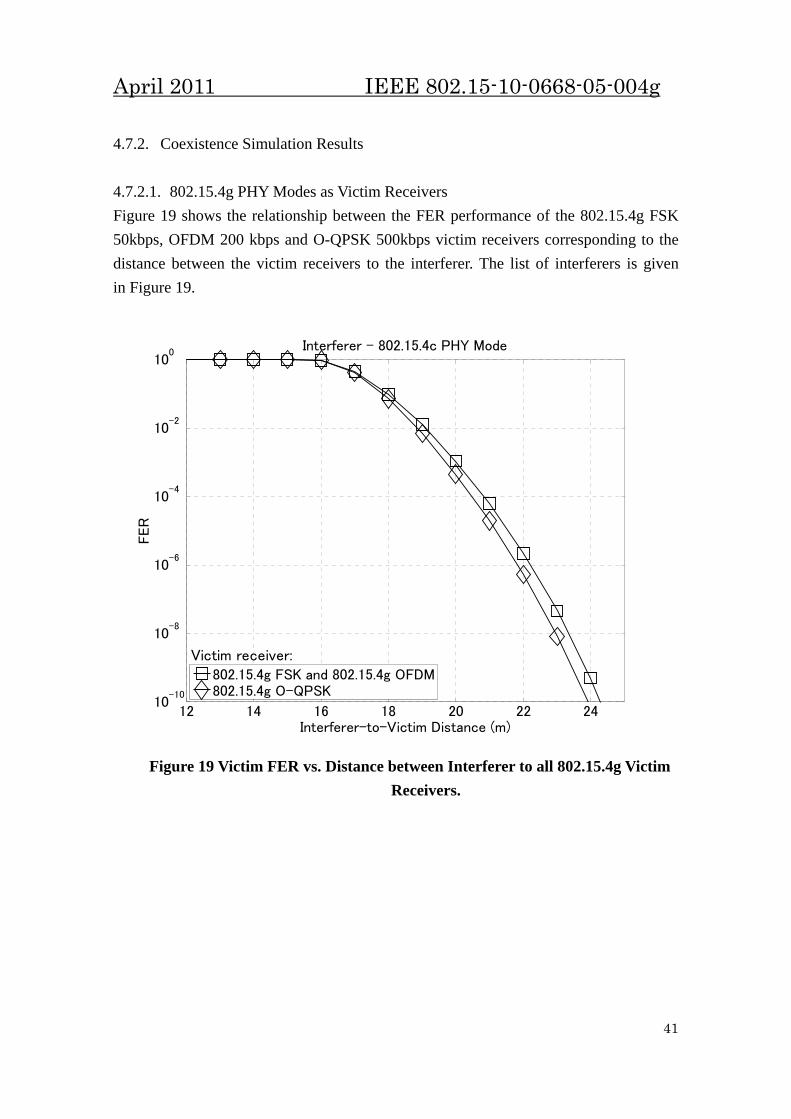
4.7.2. Coexistence Simulation Results 4.7.2.1. 802.15.4g PHY Modes as Victim Receivers Figure 19 shows the relationship between the FER performance of the 802.15.4g FSK 50kbps, OFDM 200 kbps and O-QPSK 500kbps victim receivers corresponding to the distance between the victim receivers to the interferer. The list of interferers is given in Figure 19.
12 14 16 18 20 22 2410
-10
10-8
10-6
10-4
10-2
100
Interferer-to-Victim Distance (m)
FER
Interferer - 802.15.4c PHY Mode
802.15.4g FSK and 802.15.4g OFDM802.15.4g O-QPSK
Victim receiver:
Figure 19 Victim FER vs. Distance between Interferer to all 802.15.4g Victim
Receivers.
41
April 2011 IEEE 802.15-10-0668-05-004g
4.7.2.2. 802.15.4c PHY Modes as Victim Receivers This sub-clause presents the results setting other 802 systems as the victim and 802.15.4g as the interferer. Figure 20 shows the relationship between the FER performances of the 802.15.4c (one PHY mode) victim receivers corresponding to the distance between the victim receivers to the 802.15.4g interferers. The list of interferers is given in the figure.
12 14 16 18 20 2210
-10
10-8
10-6
10-4
10-2
100
Interferer-to-Victim Distance (m)
FER
Interferer - All 802.15.4g PHY Modes
802.15.4c O-QPSK
Victim receiver:
Figure 20 Victim FER vs. Distance between Interferer to 802.15.4c Victim
Receiver. All 802.15.4g PHY modes in Table 12 display nearly similar characteristics as interferers.
42
April 2011 IEEE 802.15-10-0668-05-004g
5. Detailed Coexistence Analysis and Interference Avoidance/Mitigation Techniques 5.1. Channel Alignment The channel alignment among 802.15.4g systems and other 802 systems are summarized in Table 13, Table 14, Table 15, Table 16 and Table 17 for respective bands within which multiple systems are coexisting. By knowing the locations of center frequencies and system bandwidth for different systems, it is possible to identify and occupy channels with the least likelihood to interfere or be interfered by other coexisting systems. The tables show the center frequencies for respective systems, while the system bandwidth can be obtained from Table 7, Table 8, Table 9, Table 10, Table 11 and Table 12. 5.1.1. 2400-2483.5 MHz (Worldwide)
Table 13 Channel Alignment for Systems in the 2400-2483.5 MHz Band 802.15.4g 802.11b 802.11g 802.11n 802.15.1 802.15.3 802.15.4
Table 17 Channel Alignment for Systems in the 779-787 MHz Band 802.15.4g 802.15.4c
MR- MR- O-QPSK MPSK
O-QPSK OFDM DSSS DSSS
779.4
779.8
780 … 780 780
…
782 … 782 782
…
784 … 784 784
…
786 … 786 786
…
786.6
5.2. Coexistence with Transmit Power Control The specifications of IEEE draft standard 802.15.4g addresses low data rate, wireless, smart metering utility networks with a key attribute of low power consumption. An effective control of transmit power not only reduces the power consumed for transmit operation by a SUN device but it also helps with coexistence of a SUN device with other devices sharing the same spectrum in conjuction with other key SUN device attributes such as an inherent low duty cycle of operation, possible minimization of air time by communicating only when a coordinated handshake has occurred. Each SUN device can reduce the amount of interference it generates for the other coexisting devices by keeping its transmitted output power at the minimum level needed to achieve reliable communication. A SUN device can implement a simple mechanism of controlling its transmitted power using a measurement of the received coex-beacon power. The plot in Figure 21 shows using Hata’s Model (see section 4.2.3) the path loss
48
April 2011 IEEE 802.15-10-0668-05-004g
and the received coex-beacon strength as a function of the distance between the coex beacon transmitting coordinator and a receiving SUN device.
0 10 20 30 40 50 60 70 80 90 1000
20
40
60
80
100
120
Distance between Co-ordinator and SUN Device (m)
Pat
h Lo
ss (d
B)
Rx Coex Beacon Power as a function of distance between a co-ordinator and a SUN Device
0 10 20 30 40 50 60 70 80 90 100-80
-60
-40
-20
0
20
40
Coe
x B
eaco
n P
ower
Rec
eive
d (d
Bm
)
Figure 21 Coex-beacon signal power as a function of the path loss due to
inter-device distance The SUN device receiving the coex-beacon can make a measurement of the received coex-beacon signal strength, e.g., using a mechanism such as received signal strength indictor (RSSI), which can also be used by the automatic gain control mechanism for the receiver chain, to estimate the strength of the incident coex-beacon signal say Pbeacon_rx. The SUN device can then perform a simple calculation to determine the TX power that it should use to communicate with the coordinator transmitting the coex-beacon as follows: Let Ptx,max Maximum allowable TX output power (dBm) Ptx,min Minimum allowable TX output power (dBm) Ptx,step TX power control step size (dB)
49
April 2011 IEEE 802.15-10-0668-05-004g
Pbeacon Transmitted power of the beacon (assume 30 dBm) RX_min_sensitivity Minimum RX sensitivity of a SUN device (using -90 dBm) RX_SNRmin Minimum SNR desired for transmission (assume 4 dB) Then,
Ptx = max(min(Ptx,max, (Pbeacon - Pbeacon_rx) + RX_min_sensitivity + RX_SNRmin),Ptx_min) If the TX power is implemented with a gain step size of Ptx,step, the quantized TX power can be computed as:
Ptx, quant = round(Ptx/ Ptx,step)* Ptx,step
An example calculation for the Transmitter power control for a distance of up to 250m around the co-ordinator using assumptions of Ptx,max = 30dBm, Ptx,min = -30dBm, Ptx,step = 6dB, Pbeacon = 30dBm, RX_min_sensitivity = -90dBm, RX_SNRmin = 4dB is shown below:
0 50 100 150 200 250-100
-80
-60
-40
-20
0
20
40
Distance between Co-ordinator and SUN Device (m)
Pow
er (d
Bm
)
Transmit Power Control using Coex Beacon Measurement
Coex Beacon PowerTransmit PowerTransmit Power Quantized
Figure 22 1W TX power control using coex-beacon signal power measurement
50
April 2011 IEEE 802.15-10-0668-05-004g
0 50 100 150 200 250-100
-80
-60
-40
-20
0
20
40
Distance between Co-ordinator and SUN Device (m)
Pow
er (d
Bm
)
Transmit Power Control using Coex Beacon Measurement
Coex Beacon PowerTransmit PowerTransmit Power Quantized
Figure 23 1mW TX power control using coex-beacon signal power measurement
It is evident using Figure 22 and Figure 23 that using the proposed scheme, the TX transmits at less than full power for 76% of the time. The power consumption in an efficient implementation of the TX heavily depends on the transmitted output power. Use of a power control mechanism, such as described can result in potentially a saving of 62% of average power consumed1 in the TX operation by SUN devices assuming a uniformly distributed mesh of SUN devices around a centrally located coordinator. For the frequency bands in which the TX output power is limited to 100μW (or Ptx,max = 20 dBm), assuming that the minimum TX controllable power Ptx,min = -22dBm, implementing a power control strategy as described above results in use of less than max transmit power for 42% of the time. Correspondingly, this results in a 16.4% saving in the power consumed by the transmit operation.
·, , w nce
1 The power savings have been computed using a TX power consumption profile of the form here α is the power consumption of TX at Ptx,min, β is the power consumption differe
between Ptx,max and Ptx,min and γ is an implementation dependant power scaling constant.
51
April 2011 IEEE 802.15-10-0668-05-004g
5.3. Coexistence with Low Duty Cycle f the signal duration to the regular interval or
igure 24 below shows the data throughput for a SUN device, which is being duty
Duty cycle is known as the proportion operiod of time. A part of devices specified in 802.15.4g SUN, primarily the battery-powered devices, operate in a very low duty cycle. While typical network device may operate at duty cycle as low as below 1%, the coordinators may operate at duty cycle of around 10%, as described in E5.4 [B4]. These low duty cycle devices only transmit energy into the air for a short duration in a long interval, and are less likely to cause interference to other co-located networks. In fact, a combination of low transmission duty cycle, low transmit power and use of appropriate spacing for CCA greatly reduces the average probability of blocking/interference by a SUN device to its neighbors. Fcycled. The plots assume a minimal communication overhead of 15% only. Accounting for the typical data throughput overhead due to coding, framing, redundancy and MAC; a more practical 60% overhead case is shown in Figure 25. The power consumption in a communication device is proportional to its active time. The data suggests that for a required set of data symbols to be transmitted, it is more power efficient if a higher data rate (if possible with comparable power consumption) is chosen and the active duty cycle of the SUN communication device is lowered.
52
April 2011 IEEE 802.15-10-0668-05-004g
1
10
100
1000
10000
100000
1000000
0.1 0.2 0.5 1 2 5 10 20 50
Data throug
hput (b
ps)
Duty Cycle (%)
Effective Data throughput of a SUN device operating at a low duty cycle with a 15% Overhead
10 kb/s
50 kb/s
100 kb/s
200 kb/s
400 kb/s
500 kb/s
800 kb/s
Figure 24 SUN device throughput rate operating at a low duty cycle with a
15% throughput overhead for various PHY data rates.
1
10
100
1000
10000
100000
1000000
0.1 0.2 0.5 1 2 5 10 20 50
Data throug
hput (b
ps)
Duty Cycle (%)
Effective Data throughput of a SUN device operating at a low duty cycle with a 60% Overhead
10 kb/s
50 kb/s
100 kb/s
200 kb/s
400 kb/s
500 kb/s
800 kb/s
Figure 25 SUN device throughput rate operating at a low duty cycle with a
60% throughput overhead for various PHY data rates.
53
April 2011 IEEE 802.15-10-0668-05-004g
5.4 Performance of CSM MPM is an interference avoidance mechanism equipped with a common signaling known as CSM. CSM is a PHY mode employed for different PHYs within the 802.15.4g to negotiate among each other prior to starting respective networks. While the MPM protocols and the PHY specification of CSM are clearly outlined, the receiver design is implementation-dependent. In this section, the performance of CSM is evaluated. The system model is constructed by an FSK transmitter, the 900MHz propagation channel (typically a two-path Rayleigh fading channel) and two different types of receivers, the correlator and the energy detector. In actual implementations, receiver design may choose either one to capture the CSM in order to detect the presence of an already existing system in the channel. Figure 26 shows the performance for both the BER for the correlator and the mis-detection probability Pmd for the energy detector. The results of the performance determine the likelihood of detecting presence/absence of the CSM, thus the effective ness of coexistence. It is observed that the correlator has an approximately 25dB improvement as compared to energy detector at FER=0.01, i.e. the required error criterion.
0 10 20 30 40 50 60
10-4
10-3
10-2
10-1
SNR (dB)
BER
, P
md
CorrelatorEnergy Detection
Figure 26 Performance comparison between CSM correlator and energy detector. Horizontal line across BER=5*10-5 is the equivalent BER for
FER=0.01, as required in 802.15.4g.
54
April 2011 IEEE 802.15-10-0668-05-004g
6. Discussions and Conclusion This document has presented the overview of coexistence analysis for the IEEE 802.15.4g and other IEEE 802 systems. Firstly, the document listed all the involved homogeneous systems within the 802.15.4g and heterogeneous systems across other 802 systems. Secondly, an overview of all the available coexistence mechanisms applicable to 802.15.4g is given. Thirdly, analysis on performance due to coexisting/co-locating systems is presented considering no assistance from any coexistence mechanisms. Fourthly, mechanisms for the purpose of interference avoidance/mitigation for 802.15.4g are proposed and evaluated. To comprehensively describe the findings of the coexistence evaluation, parameter dcri is defined as the critical distance below where the interferer causes performance degradation greater than that required by respective standards. As an example, the required FER for 802.15.4g MR-FSK is 0.01, dcri is the minimum distance between victim receiver and interferer transmitter that gives FER=0.01 along the MR-FSK FER curve. If the distance becomes smaller than dcri, FER will be degraded beyond the required value of 0.01. Table 18 summarizes the values of parameter dcri for frequency bands with coexisting heterogeneous systems. It is observed that even without any coexistence mechanism, the 802.15.4g system are able to achieve the required FER given that an interferer is located as near as 12m away. Furthermore, with the employment of various coexistence mechanism listed in this document, a more harmonious radio environment can be achieved.
Table 18 Critical distance dcri for 802.15.4g in different frequency bands. Interferer: Other 802 systems. Victim: 802.15.4g systems.
Frequency Band dcri 2400-2483.5 MHz (Worldwide) ~12-25m
902-928 MHz band (United States) ~12-20m 863-870 MHz band (Europe) ~12-20m 950-958 MHz band (Japan) ~12-30m 779-787 MHz band (China) ~20m
55
April 2011 IEEE 802.15-10-0668-05-004g
Annex A Matlab Program for Plotting BER/FER Curves for 802.15.4g PHY Modes %%%%%%%%%%%%%%%%%%%% Parameter Settings %%%%%%%%%%%%%%%%%%%%%%%%%%%%
SINR = 0:20; % SINR (Ec/N0) in dB
trellisOFDMOQPSK = poly2trellis(7,[133 171]); % convolutional code generators for OFDM and DSSS QPSK
spectOFDMOQPSK = distspec(trellisOFDMOQPSK);
L_FSK50 = 250*8; % frame length for FSK 50kbps
L_OFDM200 = 20*8; % frame length for OFDM QPSK 200kbps
L_OQPSK500 = 20*8; % frame length for DSSS O-QPSK 500kbps
modlev_FSK50 = 1; % modulation level for FSK 50kbps
modlev_OFDM200 = 2; % modulation level for OFDM 200kbps
modlev_OQPSK500 = 2; % modulation level for OQPSK 500kbps
Rfec_FSK50 = 1; % FEC coding rate for FSK 50kbps
Rfec_OFDM200 = 0.5; % FEC coding rate for OFDM 200kbps
Rfec_OQPSK500 = 0.5; % FEC coding rate for OQPSK 500kbps
SF_FSK50 = 1; % spreading factor for FSK 50kbps
SF_OFDM200 = 1; % spreading factor for OFDM 200kbps
SF_OQPSK500 = 2; % spreading factor for OQPSK 500kbps
%%%%%%%%%%%%%%%%%%%%%%%% Per-bit Energy Calculations %%%%%%%%%%%%%%%%%%%
FER_FSK50 = 1-((1-BER_FSK50).^L_FSK50); % FER for FSK 50kbps
FER_OFDM200 = 1-((1-BER_OFDM200).^L_OFDM200); % FER for OFDM QPSK 200kbps
FER_OQPSK500 = 1-((1-BER_OQPSK500).^L_OQPSK500); % FER for DSSS O-QPSK 500kbps
56
April 2011 IEEE 802.15-10-0668-05-004g
Matlab Program for Plotting BER/FER Curves for Other 802.11/15 PHY Modes in the 2400-2483.5 MHz Band % BER and FER calculation for 802 systems in the 2.4GHz band
FER_11b = 1-((1-BER_11b).^L_11b); % FER for 802.11b CCK 11Mbps
FER_11g = 1-((1-BER_11g).^L_11g); % FER for 802.11g OFDM 6Mbps
FER_11n = 1-((1-BER_11n).^L_11n); % FER for 802.11n OFDM 18Mbps
FER_15_1 = 1-((1-BER_15_1).^L_15_1); % FER for 802.15.1 FHSS 1Mbps
FER_15_3 = 1-((1-BER_15_3).^L_15_3); % FER for 802.15.3 SC 22Mbps
FER_15_4 = 1-((1-BER_15_4).^L_15_4); % FER for 802.15.4 DSSS 250kbps
58
April 2011 IEEE 802.15-10-0668-05-004g
Matlab Program for Plotting FER Curves of the 802.15.4g FSK PHY Mode in response to Interference Generated by Other 802 Systems in the 2400-2483.5 MHz Band *This program is used to analyze systems other than the 802.15.4g FSK as the victim receiver by replacing the relevant parameters. *This program is also used to analyze frequency bands other than the 2400-2483.5 MHz band by replacing the relevant parameters. % 802.15.4g FSK as the victim receiver
% Txv and Rxv - 802.15.4g FSK 50kbps
% Txi - 802.11b CCK 11Mbps and 802.11g 6Mbps
% Interferer and Victim Parameters
IV_Para.P_Tv = 0; % victim TX transmit power in dBm
IV_Para.P_Ti = 14; % interferer TX transmit power in dBm
IV_Para.BW_Rv = 200e3; % bandwidth for victim receiver in Hz
IV_Para.BW_Ti = 22e6; % bandwidth for interferer in Hz
IV_Para.d_D = 0.01; % victim transmitter to victim receiver distance in km
IV_Para.d_U = [0.001:0.001:1]; % interferer transmitter to victim receiver distance in km