117
Basics of Networking

Basics of
Networking

Network
• Interconnection of two or more devices is called as a network.
• The communication between two or more interconnected devices is called
networking.
• An internetwork is a connection of two or more networks.
• Internetworking means communication between different networks.

Types of Networks
• LAN
Local Area Networks are used to connect networking devices that are in avery close geographic area such as a floor of a building, a building itself orwithin a campus.
• MAN
Metropolitan Area Network are used to connect networking devices thatmay span around the entire city.
• WAN
Wide Area Networks which connects two or more LANs present at differentgeographical locations.

LAN
LANHUB
Banjara Hills
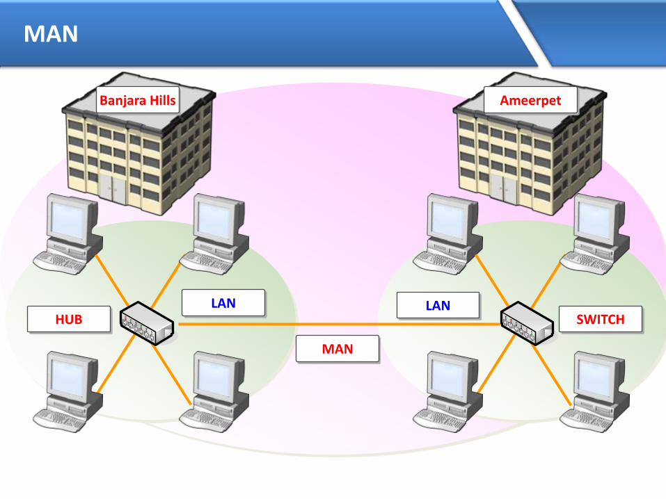
MAN
LANLANHUB SWITCH
MAN
Banjara Hills Ameerpet

WAN
LANLAN
HUB SWITCH
Hyderabad vijayawada
www.cms.com
WAN
Router Router

Basic requirements to form a network
• NIC (Network interface card) also called as LAN card
• Media
• Networking devices (Hub, Switch, Router, etc.)
• Protocols
• Logical Address (IP address)

NIC(Network Interface Card)
• NIC is the interface between the computer and the network
• It is also known as the Lan card or Ethernet card
• Ethernet cards have a unique 48 bit address called as MAC (Media access
control) address
– MAC address is also called as Physical address or hardware address
– The 48 bit MAC address is represented as 12 Hexa-decimal digits
– Example: 0 0 1 6 . D 3 F C . 6 0 3 F
• Network cards are available in different speeds
– Ethernet (10 Mbps)
– Fast Ethernet (100 Mbps)
– Gigabit Ethernet (1000 Mbps)

Media
• The purpose of the media is to transport bits from one machine to another.
Media
Guided Unguided
Co-axial Twisted pair Fiber
UTP STP
Infrared RF

Media
UTP Cable
Co-axial cable
Fiber optic

Networking devices
The various types of networking devices are:
• Repeater
• Hub
• Bridge
• Switch
• Router

Hub / Repeater
• It is not an Intelligent Device.
• It works with bits.
• Uses broadcast for communication.
• Bandwidth is shared.
• Half-duplex communication.

Functions of HUB
HUB
Data
DataDataDataData

Functions of HUB
HUB
Data
DataDataDataData
Data

Switch
• It is an Intelligent device.
• It maintains MAC address table (hardware address).
• Each port of the switch has fixed bandwidth.
• It works with Flooding and Unicast.
• Supports full duplex communication

Functions of a Switch
• MAC Address Learning
• Forwarding

Functions of Switch
1
23
4 5 67
8

Functions of Switch
MAC ADDRESS TABLE
PORT MAC-ADDRESS
1
2
3
4
5
6
7
8
001C-C01A-0002
001C-C01A-0004
001C-C01A-0002
1
23
4 5 67
8
S
D
DataDataDataDataDataData
Data
Source MAC001C.C01A.0002
Destination MAC001C.C01A.0004
DATA
Source MAC001C.C01A.0002
Destination MAC001C.C01A.0004
DATA

Functions of Switch
MAC ADDRESS TABLE
PORT MAC-ADDRESS
Fa0/1
Fa0/2 001C-C01A-0002
Fa0/3
Fa0/4
Fa0/5
Fa0/6
Fa0/7
Fa0/8
001C-C01A-0004
001C-C01A-0002
001C-C01A-0004
1
23
4 5 67
8
D
S Data

Difference between Bridge and Switch
Bridge
• Bridges are software based
• Bridges have less number
of ports
• Generally used for
connecting two different
topology (Segment)
Switch
• Switches are hardware
based
• Switches have more ports
• Generally used for
connecting single topology
(Segment)

Router
• It is an Intelligent device
• It works with Logical Addressing (i.e. IP, IPX, AppleTalk)
• It works with Fixed bandwidth

Interconnecting Network Devices
PC HUB Bridge Switch Router
PC Cross Cable Straight Cross Cable Straight Cross Cable
HUB Straight Cross Cable Straight Cross Straight
Bridge Cross Cable Straight Cross Cable Straight Cross Cable
Switch Straight Cross Straight Cross Cable Straight
Router Cross Cable Straight Cross Cable Straight Cross Cable

Topology
Topology is a physical layout of the systems connected in a network.
Different types of topology are:
• Bus
• Ring
• Mesh
• Star

Bus Topology
• In bus topology all devices are connected to a single cable or backbone.
• It supports half duplex communication.
• A break at any point along the backbone will result in total network failure.

Ring Topology
• In ring topology each computer or device is connected to its neighborforming a loop.
• Failure of a single device or a break anywhere in the cable causes the fullnetwork to stop communicating

Mesh Topology
• In mesh topology each device is directly connected to all other devices
• The disadvantage is the number of NIC’s required on each device and the
complex cabling.

Star Topology
• The most commonly used topology
• It consist of one centralized device which can be either a switch or a hub.
• The devices connect to the various ports on the centralized devices.
HUB/Switch


IP Address
• IP Address is a Logical Address
• It is a Network Layer address (Layer 3)
• Two Versions of IP:
• IP version 4 is a 32 bit address
• IP version 6 is a 128 bit address

IP version 4
• Bit is represent by 0 or 1 (i.e. Binary)
• IP address in binary form (32 bits):
0 1 0 1 0 1 0 1 0 0 0 0 0 1 0 1 1 0 1 1 1 1 1 1 0 0 0 0 0 0 0 1
• 32 bits are divided into 4 Octets:
0 1 0 1 0 1 0 1 . 0 0 0 0 0 1 0 1 . 1 0 1 1 1 1 1 1 . 0 0 0 0 0 0 0 1
• IP address in decimal form:
85.5.191.1
First Octet Second Octet Third Octet Forth Octet

IPv4 address range
Taking Example for First Octet :
Total 8 bits, Value will be 0’s and 1’s
i.e. 2⁸ = 256 combination
27 26 25 24 23 22 21 20
0 0 0 0 0 0 0 0 = 0
0 0 0 0 0 0 0 1 = 1
0 0 0 0 0 0 1 0 = 2
0 0 0 0 0 0 1 1 = 3
0 0 0 0 0 1 0 0 = 4
1 1 1 1 1 1 1 1 = 255
Total IP Address Range
0 . 0 . 0 . 0
to
255.255.255.255

IP Address Classification
• IP Addresses are divided into 5 Classes
• CLASS A
• CLASS B
• CLASS C
• CLASS D
• CLASS E
Used in LAN & WAN
Reserved for Multicasting
Reserved for Research & Development

Priority Bit
• Priority Bit is used for IP Address classification.
• Most significant bit(s) from the first octet are selected for Priority Bit(s).
• Class A priority bit is 0
• Class B priority bits are 10
• Class C priority bits are 110
• Class D priority bits are 1110
• Class E priority bits are 1111
Class A Range
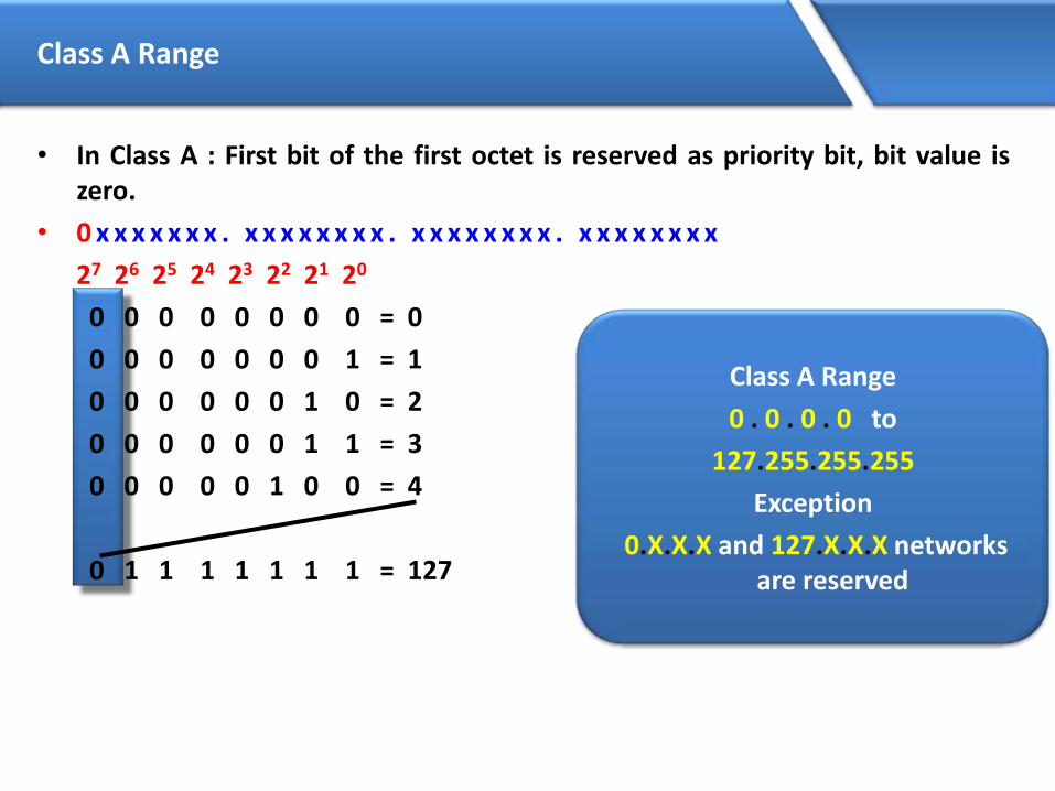
• In Class A : First bit of the first octet is reserved as priority bit, bit value iszero.
• 0 x x x x x x x . x x x x x x x x . x x x x x x x x . x x x x x x x x
27 26 25 24 23 22 21 20
0 0 0 0 0 0 0 0 = 0
0 0 0 0 0 0 0 1 = 1
0 0 0 0 0 0 1 0 = 2
0 0 0 0 0 0 1 1 = 3
0 0 0 0 0 1 0 0 = 4
0 1 1 1 1 1 1 1 = 127
Class A Range
0 . 0 . 0 . 0 to
127.255.255.255
Exception
0.X.X.X and 127.X.X.X networks are reserved

Class B Range
• In Class B : First two bits of the first octet are reserved as priority bits, bitvalue as 10.
• 1 0 x x x x x x . x x x x x x x x . x x x x x x x x . X x x x x x x x
27 26 25 24 23 22 21 20
1 0 0 0 0 0 0 0 = 128
1 0 0 0 0 0 0 1 = 129
1 0 0 0 0 0 1 0 = 130
1 0 0 0 0 0 1 1 = 131
1 0 0 0 0 1 0 0 = 132
1 0 1 1 1 1 1 1 = 191
Class B Range
128 . 0 . 0 . 0 to
191 . 255 . 255 .255
Class C Range
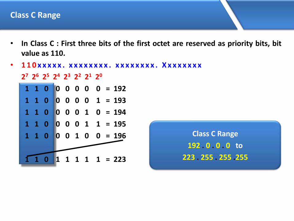
• In Class C : First three bits of the first octet are reserved as priority bits, bitvalue as 110.
• 1 1 0 x x x x x . x x x x x x x x . x x x x x x x x . X x x x x x x x
27 26 25 24 23 22 21 20
1 1 0 0 0 0 0 0 = 192
1 1 0 0 0 0 0 1 = 193
1 1 0 0 0 0 1 0 = 194
1 1 0 0 0 0 1 1 = 195
1 1 0 0 0 1 0 0 = 196
1 1 0 1 1 1 1 1 = 223
Class C Range
192 . 0 . 0 . 0 to
223 . 255 . 255 .255

Class D Range
• In Class D : First four bits of the first octet are reserved as priority bits, bitvalue as 1110.
• 1 1 1 0 x x x x . x x x x x x x x . x x x x x x x x . X x x x x x x x
27 26 25 24 23 22 21 20
1 1 1 0 0 0 0 0 = 224
1 1 1 0 0 0 0 1 = 225
1 1 1 0 0 0 1 0 = 226
1 1 1 0 0 0 1 1 = 227
1 1 1 0 0 1 0 0 = 228
1 1 1 0 1 1 1 1 = 239
Class D Range
224 . 0 . 0 . 0 to
239 . 255 . 255 .255

Class E Range
• In Class E : First four bits of the first octet are reserved as priority bits, bitvalue as 1111.
• 1 1 1 1 x x x x . x x x x x x x x . x x x x x x x x . X x x x x x x x
27 26 25 24 23 22 21 20
1 1 1 1 0 0 0 0 = 240
1 1 1 1 0 0 0 1 = 241
1 1 1 1 0 0 1 0 = 242
1 1 1 1 0 0 1 1 = 243
1 1 1 1 0 1 0 0 = 244
1 1 1 1 1 1 1 1 = 255
Class E Range
240 . 0 . 0 . 0 to
255 . 255 . 255 .255

Octet Format
• IP address is divided into Network & Host Portion
CLASS A is written as N . H . H . H
CLASS B is written as N . N . H . H
CLASS C is written as N . N . N . H

CLASS A – No. Networks & Hosts
• Class A Octet Format is N . H . H . HNetwork bits : 8 Host bits : 24
• No. of Networks= 2no of network bits– Priority bit
= 28-1 (-1 is Priority Bit for Class A)= 27
= 128 – 2 (-2 is for 0 & 127 Network)= 126 Networks
• No. of Host= 2no of host bits -2= 224 – 2 (-2 is for Network ID & Broadcast ID)= 16777216 - 2= 16777214 Hosts/Network

CLASS B – No. Networks & Hosts
• Class B Octet Format is N . N . H . H
Network bits : 16 Host bits : 16
• No. of Networks
= 2no of network bits– Priority bit
= 216-2 (-2 is Priority Bit for Class B)
= 214
= 16384 Networks
• No. of Host
= 2no of host bits -2
= 216 – 2 (-2 is for Network ID & Broadcast ID)
= 65536 - 2
= 65534 Hosts/Network
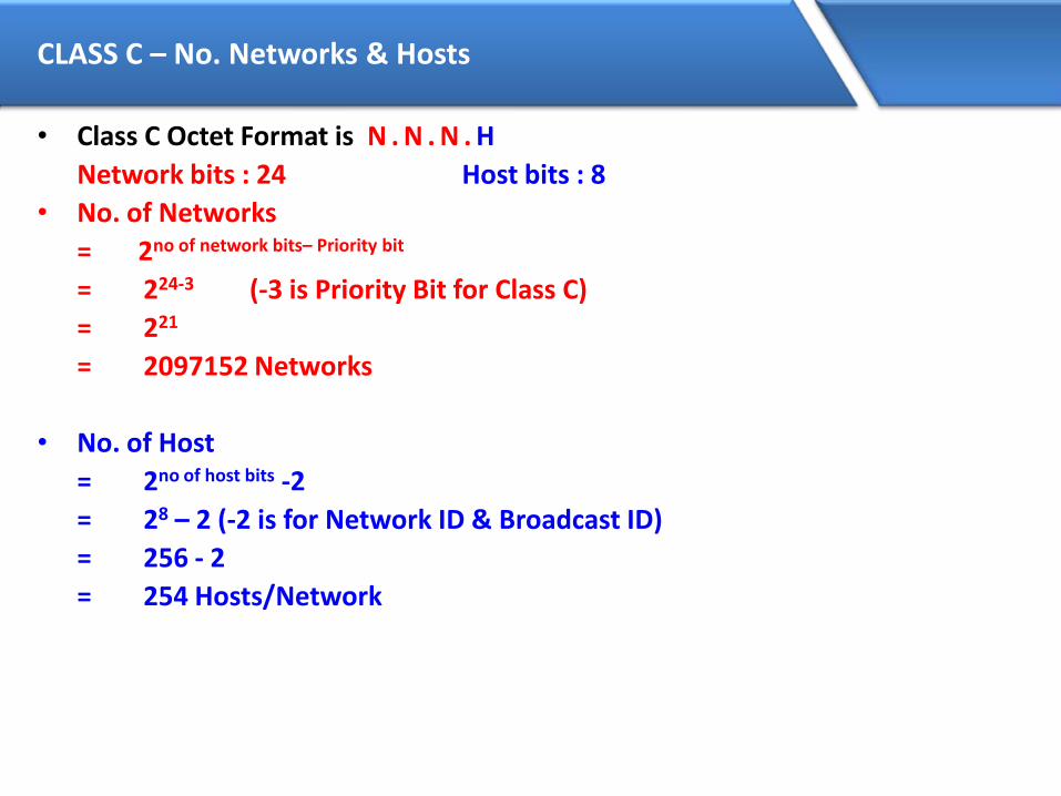
CLASS C – No. Networks & Hosts
• Class C Octet Format is N . N . N . H
Network bits : 24 Host bits : 8
• No. of Networks
= 2no of network bits– Priority bit
= 224-3 (-3 is Priority Bit for Class C)
= 221
= 2097152 Networks
• No. of Host
= 2no of host bits -2
= 28 – 2 (-2 is for Network ID & Broadcast ID)
= 256 - 2
= 254 Hosts/Network
Network & Broadcast Address
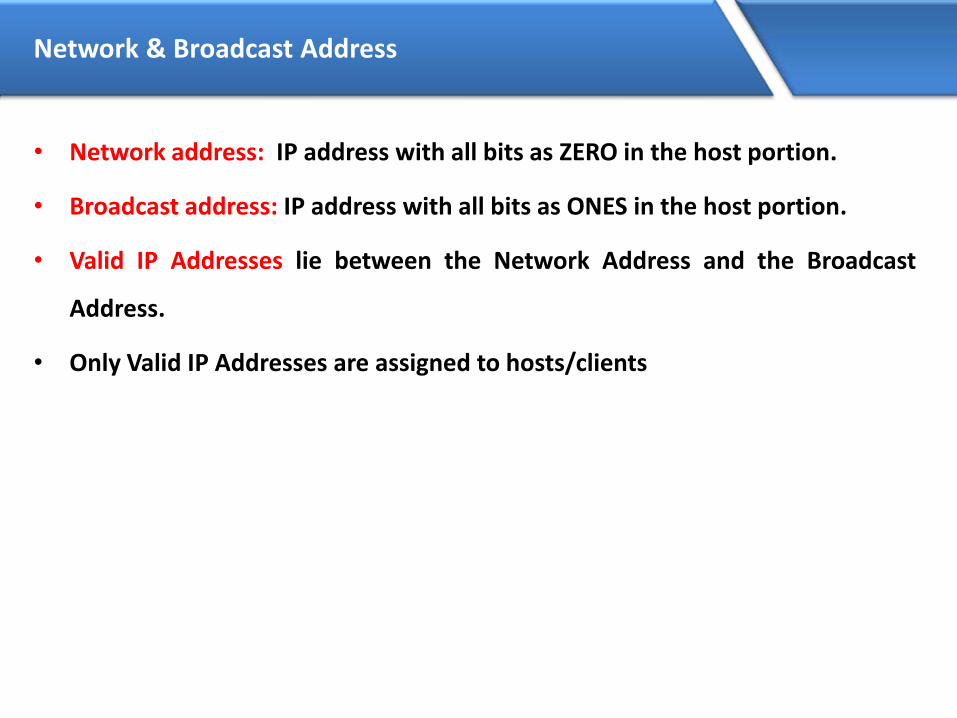
• Network address: IP address with all bits as ZERO in the host portion.
• Broadcast address: IP address with all bits as ONES in the host portion.
• Valid IP Addresses lie between the Network Address and the Broadcast
Address.
• Only Valid IP Addresses are assigned to hosts/clients

Example - Class A
• Class A : N.H.H.H
Network Address :0 x x x x x x x . 0 0 0 0 0 0 0 0 . 0 0 0 0 0 0 0 0 . 0 0 0 0 0 0 0 0Broadcast Address :0 x x x x x x x . 1 1 1 1 1 1 1 1 . 1 1 1 1 1 1 1 1 . 1 1 1 1 1 1 1 1Class A
10.0.0.0
10.0.0.1
10.0.0.2
10.0.0.3
10.255.255.254
10.255.255.255
Network Address
Broadcast Address
Valid IP Addresses
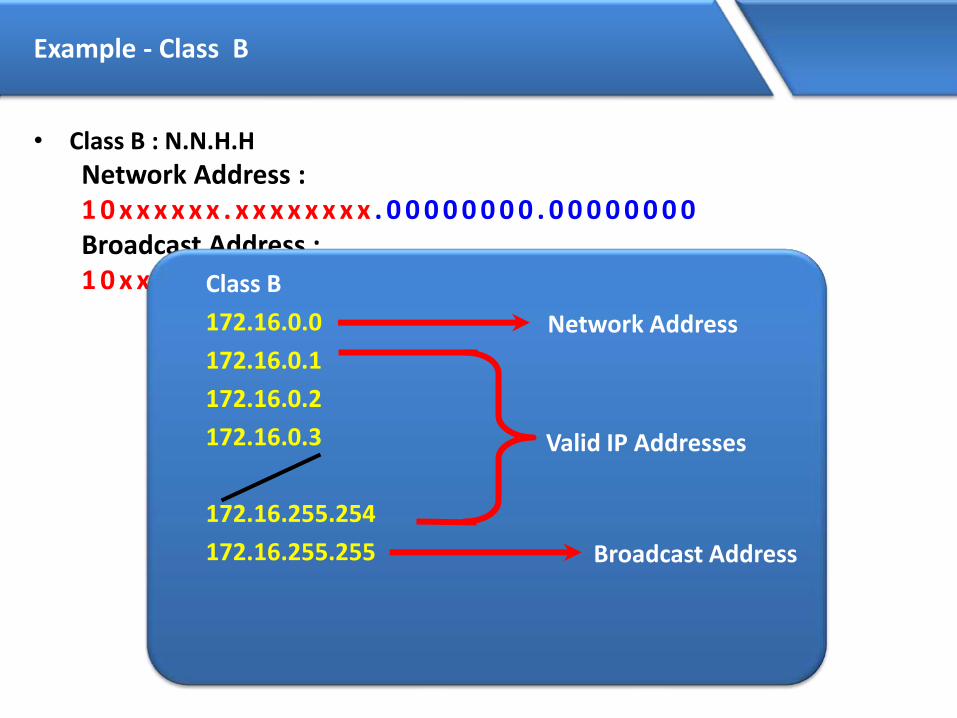
Example - Class B
• Class B : N.N.H.H
Network Address :1 0 x x x x x x . x x x x x x x x . 0 0 0 0 0 0 0 0 . 0 0 0 0 0 0 0 0Broadcast Address :1 0 x x x x x x . x x x x x x x x . 1 1 1 1 1 1 1 1 . 1 1 1 1 1 1 1 1Class B
172.16.0.0
172.16.0.1
172.16.0.2
172.16.0.3
172.16.255.254
172.16.255.255
Network Address
Broadcast Address
Valid IP Addresses

Example - Class C
• Class C : N.N.N.H
Network Address :1 1 0 x x x x x . x x x x x x x x . x x x x x x x x . 0 0 0 0 0 0 0 0Broadcast Address :1 1 0 x x x x x . x x x x x x x x . x x x x x x x x . 1 1 1 1 1 1 1 1
Class C
192.168.1.0
192.168.1.1
192.168.1.2
192.168.1.3
192.168.1.254
192.168.1.255
Network Address
Broadcast Address
Valid IP Addresses

Private IP Address
• There are certain addresses in each class of IP address that are reserved forPrivate Networks. These addresses are called private addresses.
• These addresses are not Routable (or) valid on Internet.
Class A
10.0.0.0 to 10.255.255.255
Class B
172.16.0.0 to 172.31.255.255
Class C
192.168.0.0 to 192.168.255.255

Subnet Mask
• Subnet Mask differentiates the Network and Host portions of an IP address
• Represented with all 1’s in the network portion and with all 0’s in the host
portion.

Subnet Mask - Examples
• Class A : N.H.H.H
11111111.00000000.00000000.00000000
Default Subnet Mask for Class A is 255.0.0.0
• Class B : N.N.H.H
11111111.11111111.00000000.00000000
Default Subnet Mask for Class B is 255.255.0.0
• Class C : N.N.N.H
11111111.11111111.11111111.00000000
Default Subnet Mask for Class C is 255.255.255.0

How Subnet Mask Works ?
IP Address : 192.168.1.1
Subnet Mask : 255.255.255.0
ANDING PROCESS :
192.168.1.1 = 11000000.10101000.00000001.00000001
255.255.255.0 = 11111111.11111111.11111111.00000000
==================================================
192.168.1.0 = 11000000.10101000.00000001.00000000
==================================================
The output of an AND table is 1 if both its inputs are 1.
For all other possible inputs the output is 0.


Subnetting
• Creating Multiple independent Networks from a Single Network.
• Converting Host bits into Network Bits
i.e. Converting 0’s into 1’s
• Subnetting can be performed in two ways.
– FLSM (Fixed Length Subnet Mask)
– VLSM (Variable Length subnet mask)
• Subnetting can be done based on requirement .
– Number of Networks required?
– Number of Hosts required?

Scenario for subnetting
• CMS Technologies is having 100 PCs
• Which IP address Class is preferred for the network ?
Answer : Class C.
• In CMS Technologies there are 2 Departments with 50 PCs each
CMS Technologies – 192.168.1.0/24
– MCSE 192.168.1.1 to 192.168.1.50
192.168.1.51 to 192.168.1.100– CISCO

Scenario for subnetting
LAN
HUB

Scenario for subnetting
LAN
192.168.1.20
192.168.1.30
192.168.1.40
192.168.1.50
192.168.1.60
192.168.1.70
192.168.1.80
192.168.1.90
HUB
192.168.1.10
192.168.1.100

Scenario (…continued)
• Administrator’s Requirement :
Inter-department communication should not be possible ?
Solution.
Allocate a different Network to each Department
i.e.
– MCSE 192.168.1.1 to 192.168.1.50
192.168.2.1 to 192.168.2.50– CISCO

Scenario for subnetting
LAN
HUB

Scenario for subnetting
LAN
192.168.1.2
192.168.1.3
192.168.1.4
192.168.1.50
192.168.2.1
192.168.2.2
192.168.2.3
192.168.2.4
HUB
192.168.1.1
192.168.2.50

Main Aim of Subnetting
• Problem with the previous Scenario is :-
• Wastage of IP addresses if it is public(Approximately 400)
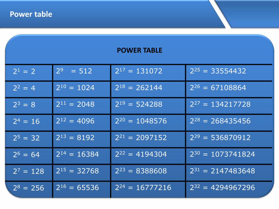
Power table
POWER TABLE
21 = 2
22 = 4
23 = 8
24 = 16
25 = 32
26 = 64
27 = 128
28 = 256
29 = 512
210 = 1024
211 = 2048
212 = 4096
213 = 8192
214 = 16384
215 = 32768
216 = 65536
217 = 131072
218 = 262144
219 = 524288
220 = 1048576
221 = 2097152
222 = 4194304
223 = 8388608
224 = 16777216
225 = 33554432
226 = 67108864
227 = 134217728
228 = 268435456
229 = 536870912
230 = 1073741824
231 = 2147483648
232 = 4294967296

Some Important Values
VALUES IN SUBNET MASK
Bit Value Mask
1 128 10000000
2 192 11000000
3 224 11100000
4 240 11110000
5 248 11111000
6 252 11111100
7 254 11111110
8 255 11111111

Requirement of Networks is 2 ?Example – 1
Class C : N.N.N.H1 1 0 x x x x x . x x x x x x x x . x x x x x x x x . x x x x x x x xClass C : 192.168.1.0No. of Subnet
= 2n – 2 ≥ Req. of Subnet= 22 – 2 ≥ 2 (-2 is for First & Last Subnet Range)= 4 – 2= 2 Subnet
No. of Host= 2h – 2 (-2 is for Network ID & Broadcast ID)= 26 – 2= 64 – 2= 62 Hosts/Subnet

Example – 1 (Continued…)
• Customized Subnet Mask =255.
11111111.
255.
11111111.
255.
11111111. 11000000
192
Range of NetworksNetwork ID Broadcast ID192.168.1.0
192.168.1.64192.168.1.128192.168.1.192
192.168.1.63192.168.1.127192.168.1.191192.168.1.255
Valid Subnets
192.168.1.0 192.168.1.63
192.168.1.192 192.168.1.255
If you convert 2 Host Bits to Network Bits
2 Subnet & 62 Hosts/Subnet
Customized Subnet Mask
255.255.255.192
Subnet Range
192.168.1.64 to 192.168.1.127 MCSE
192.168.1.128 to 192.168.1.191 CISCO


Requirement of subnet is 14?Example -2
CLASS C: N.N.N.H1 1 0 x x x x x . x x x x x x x x . x x x x x x x x . x x x x x x x xClass C : 192.168.1.0No. of Subnet= 2n – 2 ≥ Req. of Subnet= 24 – 2 ≥ 14(-2 is for First & Last Subnet Range)= 16– 2= 14 SubnetNo. of Host= 2h – 2 (-2 is for Network ID & Broadcast ID)= 24 – 2= 16 – 2= 14 Hosts/Subnet

EXAMPLE – 2 (Continued…)
Customized Subnet Mask =
255.
11111111.
255.
11111111.
255.
11111111. 11110000
240
Range of NetworksNetwork ID Broadcast ID192.168.1.0
192.168.1.16192.168.1.32192.168.1.48
192.168.1.224192.168.1.240
192.168.1.15192.168.1.31192.168.1.47192.168.1.63
192.168.1.239192.168.1.255
Valid Subnets
192.168.1.0 192.168.1.15
192.168.1.240 192.168.1.255
If you convert 4 Host Bits to Network Bits
14 Subnet & 14 Hosts/Subnet
Customized Subnet Mask
255.255.255.240
Subnet Range
192.168.1.16 to 192.168.1.31
192.168.1.32 to 192.168.1.47
192.168.1.48 to 192.168.1.63
192.168.1.64 to 192.168.1.79
192.168.1.240 to 192.168.1.255

Requirement of Hosts is 40 ?Example – 3
Class C : N.N.N.H110xxxxx.xxxxxxxx.xxxxxxxx .xxxxxxxxClass C : 192.168.1.0No. of Host
= 2h – 2 ≥ Req. of Host= 26 – 2 ≥ 40 (-2 is for Network ID & Broadcast ID)= 64 – 2= 62 Hosts/Subnet
No. of Subnet= 2n – 2 (-2 is for First & Last Subnet Range)= 22 – 2= 4 – 2= 2 Subnet

Example – 3 (Continued…)
Customized Subnet Mask =255.
11111111.
255.
11111111.
255.
11111111. 11000000
192
Range of NetworksNetwork ID Broadcast ID192.168.1.0192.168.1.64192.168.1.128192.168.1.192
192.168.1.63192.168.1.127192.168.1.191192.168.1.255
Valid Subnets
192.168.1.0 192.168.1.63
192.168.1.192 192.168.1.255
If you convert 2 Host Bits to Network Bits
2 Subnet & 62 Hosts/Subnet
Customized Subnet Mask
255.255.255.192
Subnet Range
192.168.1.64 to 192.168.1.127
192.168.1.128 to 192.168.1.191
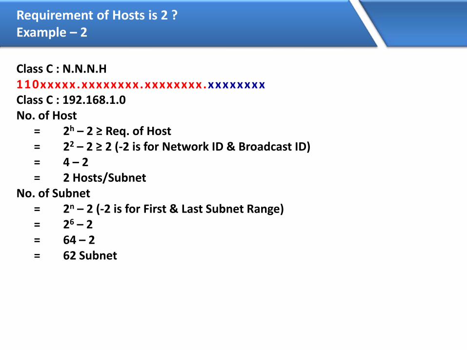
Requirement of Hosts is 2 ?Example – 2
Class C : N.N.N.H110xxxxx.xxxxxxxx.xxxxxxxx .xxxxxxxxClass C : 192.168.1.0No. of Host
= 2h – 2 ≥ Req. of Host= 22 – 2 ≥ 2 (-2 is for Network ID & Broadcast ID)= 4 – 2= 2 Hosts/Subnet
No. of Subnet= 2n – 2 (-2 is for First & Last Subnet Range)= 26 – 2= 64 – 2= 62 Subnet

Example – 2 (Continued…)
• Customized Subnet Mask =255.
11111111.
255.
11111111.
255.
11111111. 11111100
252
Range of NetworksNetwork ID Broadcast ID192.168.1.0
192.168.1.4192.168.1.8192.168.1.12
192.168.1.248192.168.1.252
192.168.1.3192.168.1.7192.168.1.11192.168.1.15
192.168.1.251192.168.1.255
Valid Subnets
192.168.1.0 192.168.1.3
192.168.1.252 192.168.1.255
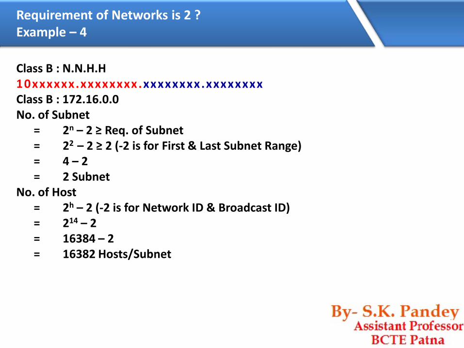
Requirement of Networks is 2 ?Example – 4
Class B : N.N.H.H10xxxxxx.xxxxxxxx .xxxxxxxx .xxxxxxxxClass B : 172.16.0.0No. of Subnet
= 2n – 2 ≥ Req. of Subnet= 22 – 2 ≥ 2 (-2 is for First & Last Subnet Range)= 4 – 2= 2 Subnet
No. of Host= 2h – 2 (-2 is for Network ID & Broadcast ID)= 214 – 2= 16384 – 2= 16382 Hosts/Subnet

Example – 4 (Continued…)
• Customized Subnet Mask =255.
11111111.
255.
11111111.
0
11000000. 00000000
192.
Range of NetworksNetwork ID Broadcast ID172.16.0.0172.16.64.0172.16.128.0172.16.192.0
172.16.63.255172.16.127.255172.16.191.255172.16.255.255
Valid Subnets
172.16.0.0 172.16.63.255
172.16.192.0 172.16.255.255

Requirement of Hosts is 126 ?Example – 5
Class B : N.N.H.H
10xxxxxx.xxxxxxxx .xxxxxxxx .xxxxxxxx
Class B : 172.16.0.0
No. of Host
= 2h – 2 ≥ Req. of Host
= 27 – 2 ≥ 126 (-2 is for Network ID & Broadcast ID)
= 128 – 2
= 126 Hosts/Subnet
No. of Subnet
= 2n – 2 (-2 is for First & Last Subnet Range)
= 29 – 2
= 512 – 2
= 510 Subnet

Example – 2 (Continued…)
• Customized Subnet Mask =
255.
11111111.
255.
11111111.
255.
11111111. 10000000
128
Range of NetworksNetwork ID Broadcast ID172.16.0.0172.16.0.128172.16.1.0172.16.1.128
172.16.255.0172.16.255.128
172.16.0.127172.16.0.255172.16.1.127172.16.1.255
172.16.255.127172.16.255.255
Valid Subnets
172.16.0.0 172.16.0.127
172.16.255.128 172.16.255.255

VLSM
• Subnetting a subnet is called as Variable Length Subnet Mask
• VLSMs provide the capability to include more than one subnet mask within
a major network

Scenario
• ZOOM Technologies is having 100 PC
ZOOM Technologies – 192.168.1.0/24
– MCSE
– CISCO
– FIREWALL
– SOLARIS
– TRAINING
Administrator’s requirement : Inter-department communication should not be possible ?
Best Solution is :
FLSM i.e. Subnetting

Scenario (…continued)
• Now we are also having sub departments ZOOM Technologies
– MCSE
– CISCO
– CCNA
– CCNP
– FIREWALL
– ISA
– Checkpoint
– NetASQ
– Clavister
– Cisco PIX
– SOLARIS
– Linux
– Unix
– Solaris
– TRAINING
Scenario (…continued)
Administrator does not want inter-department communication in the subdepartments ?
Answer : You will use the subnet range to further divide it into smaller ranges,this time its Subnetting of a Subnet i.e. VLSM.
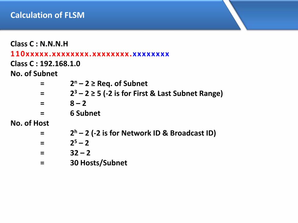
Calculation of FLSM
Class C : N.N.N.H110xxxxx.xxxxxxxx.xxxxxxxx .xxxxxxxxClass C : 192.168.1.0No. of Subnet
= 2n – 2 ≥ Req. of Subnet= 23 – 2 ≥ 5 (-2 is for First & Last Subnet Range)= 8 – 2= 6 Subnet
No. of Host= 2h – 2 (-2 is for Network ID & Broadcast ID)= 25 – 2= 32 – 2= 30 Hosts/Subnet

Example – 1 (Continued…)
• Customized Subnet Mask =
255.
11111111.
255.
11111111.
255.
11111111. 11100000
224
Range of NetworksNetwork ID Broadcast ID192.168.1.0192.168.1.32192.168.1.64192.168.1.96192.168.1.128192.168.1.160192.168.1.192192.168.1.224
192.168.1.31192.168.1.63192.168.1.95192.168.1.127192.168.1.159192.168.1.191192.168.1.223192.168.1.255
Valid Subnets
192.168.1.0 192.168.1.31
192.168.1.224 192.168.1.255

Assigning of the Ranges
ZOOM Technologies – MCSE– CISCO
– CCNA– CCNP
– FIREWALL– ISA– Checkpoint– NetASQ– Clavister– Cisco PIX
– SOLARIS– Linux– Unix– Solaris
– TRAINING
192.168.1.32 – 1.63/27
192.168.1.64 – 1.95/27
192.168.1.96 – 1.127/27
192.168.1.128 – 1.159/27
192.168.1.160 – 1.191/27

Calculation of VLSM for CISCO Dept.
Class C : N.N.N.H110xxxxx.xxxxxxxx.xxxxxxxx .xxxxxxxxClass C : 192.168.1.64No. of Subnet
= 2n ≥ Req. of Subnet= 21 ≥ 2= 2= 2 Subnet
No. of Host= 2h – 2 (-2 is for Network ID & Broadcast ID)= 24 – 2= 16 – 2= 14 Hosts/Subnet
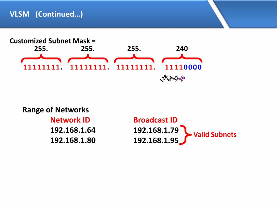
VLSM (Continued…)
Customized Subnet Mask =255.
11111111.
255.
11111111.
255.
11111111. 11110000
240
Range of NetworksNetwork ID Broadcast ID192.168.1.64192.168.1.80
192.168.1.79192.168.1.95
Valid Subnets
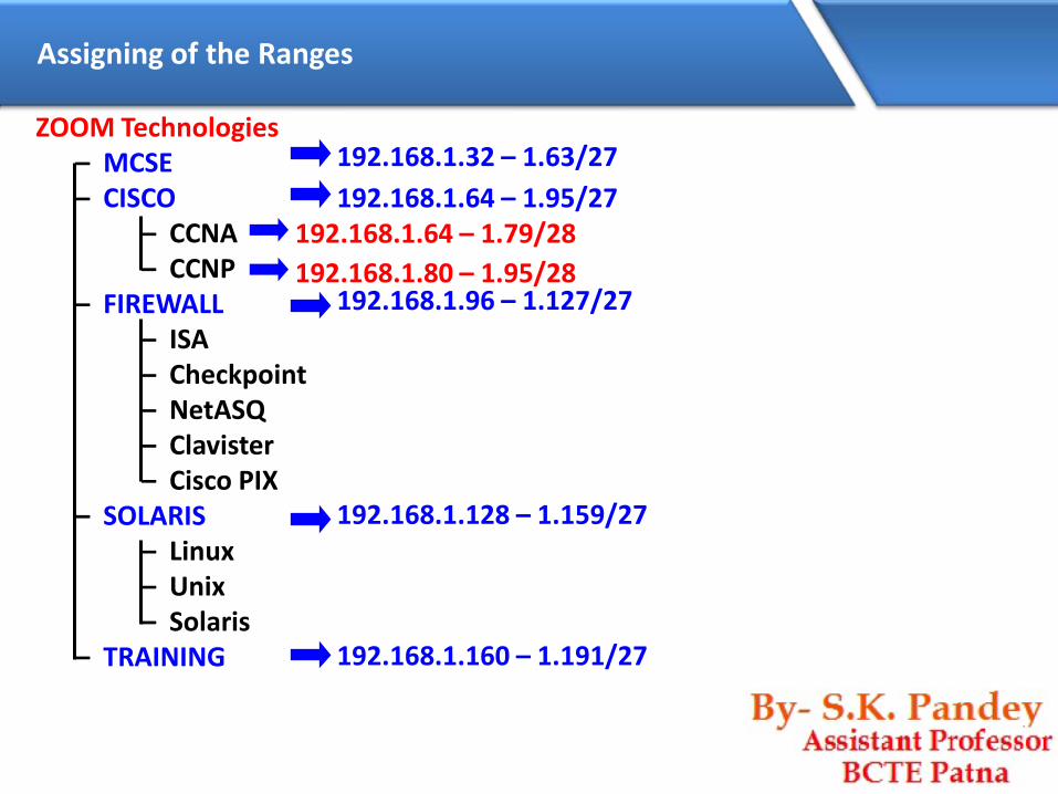
Assigning of the Ranges
192.168.1.64 – 1.79/28
192.168.1.80 – 1.95/28
ZOOM Technologies – MCSE– CISCO
– CCNA– CCNP
– FIREWALL– ISA– Checkpoint– NetASQ– Clavister– Cisco PIX
– SOLARIS– Linux– Unix– Solaris
– TRAINING
192.168.1.32 – 1.63/27
192.168.1.64 – 1.95/27
192.168.1.96 – 1.127/27
192.168.1.128 – 1.159/27
192.168.1.160 – 1.191/27

Calculation of VLSM for Firewall Dept.
Class C : N.N.N.H110xxxxx.xxxxxxxx.xxxxxxxx .xxxxxxxxClass C : 192.168.1.96No. of Subnet
= 2n ≥ Req. of Subnet= 23 ≥ 5= 8= 8 Subnet
No. of Host= 2h – 2 (-2 is for Network ID & Broadcast ID)= 22 – 2= 4 – 2= 2 Hosts/Subnet
110xxxxx.xxxxxxxx.xxxxxxxx.xxxxxx xx

VLSM (Continued…)
Customized Subnet Mask =
255.
11111111.
255.
11111111.
255.
11111111. 11111100
252
Range of NetworksNetwork ID Broadcast ID192.168.1.96192.168.1.100192.168.1.104192.168.1.108192.168.1.112192.168.1.116192.168.1.120192.168.1.124
192.168.1.99192.168.1.103192.168.1.107192.168.1.111192.168.1.115192.168.1.119192.168.1.123192.168.1.127
Valid Subnets

Assigning of the Ranges
192.168.1.96 – 1.99/30192.168.1.100 – 1.103/30
192.168.1.104 – 1.107/30192.168.1.108 – 1.111/30192.168.1.112 – 1.115/30
ZOOM Technologies – MCSE– CISCO
– CCNA– CCNP
– FIREWALL– ISA– Checkpoint– NetASQ– Clavister– Cisco PIX
– SOLARIS– Linux– Unix– Solaris
– TRAINING
192.168.1.32 – 1.63/27
192.168.1.64 – 1.95/27
192.168.1.96 – 1.127/27
192.168.1.128 – 1.159/27
192.168.1.160 – 1.191/27
192.168.1.64 – 1.79/28
192.168.1.80 – 1.95/28

Calculation of VLSM for Solaris Dept.
Class C : N.N.N.H110xxxxx.xxxxxxxx.xxxxxxxx .xxxxxxxxClass C : 192.168.1.128No. of Subnet
= 2n ≥ Req. of Subnet= 22 ≥ 3= 4= 4 Subnet
No. of Host= 2h – 2 (-2 is for Network ID & Broadcast ID)= 23 – 2= 8 – 2= 6 Hosts/Subnet

VLSM (Continued…)
• Customized Subnet Mask =255.
11111111.
255.
11111111.
255.
11111111. 11111000
248
Range of NetworksNetwork ID Broadcast ID192.168.1.128192.168.1.136192.168.1.144192.168.1.152
192.168.1.135192.168.1.143192.168.1.151192.168.1.159
Valid Subnets

Assigning of the Ranges
192.168.1.128 – 1.135/29192.168.1.136 – 1.143/29192.168.1.144 – 1.151/29
ZOOM Technologies – MCSE– CISCO
– CCNA– CCNP
– FIREWALL– ISA– Checkpoint– NetASQ– Clavister– Cisco PIX
– SOLARIS– Linux– Unix– Solaris
– TRAINING
192.168.1.32 – 1.63/27
192.168.1.64 – 1.95/27
192.168.1.96 – 1.127/27
192.168.1.128 – 1.159/27
192.168.1.160 – 1.191/27
192.168.1.96 – 1.99/30192.168.1.100 – 1.103/30
192.168.1.104 – 1.107/30192.168.1.108 – 1.111/30192.168.1.112 – 1.115/30
192.168.1.64 – 1.79/28
192.168.1.80 – 1.95/28


OSI
• OSI was developed by the International Organization for Standardization
(ISO) and introduced in 1984.
• It is a layered architecture (consists of seven layers).
• Each layer defines a set of functions which takes part in data
communication.

OSI Model Layers
Application
Presentation
Session
Transport
Network
Data Link
Physical
Layer - 7
Layer - 6
Layer - 5
Layer - 4
Layer - 3
Layer - 2
Layer - 1
User support Layers
or
Software Layers
Network support Layers
or
Hardware Layers
Core layer of the OSI

Application Layer
• Application Layer is responsible for providing an interface for the users to interact with application services or Networking Services .
• Ex: Web browser, Telnet etc.
Application
Presentation
Session
Transport
Network
Data Link
Physical
Application

Examples of Networking Services
Service Port No.
HTTP 80
FTP 21
SMTP 25
TELNET 23
TFTP 69

Data flow from Application Layer
Application
2180 25 6753 69
Session
Transport
Network
Data Link
Physical
Presentation
Data

Presentation Layer
Presentation Layer It is responsible fordefining a standard format to the data.
It deals with data presentation.
The major functions described at this layer are..
Encoding – Decoding
Eg: ASCII, EBCDIC (Text)
JPEG,GIF,TIFF (Graphics)
MIDI,WAV (Voice)
MPEG,DAT,AVI (Video)
Encryption – Decryption
Compression – Decompression
Application
Presentation
Session
Transport
Network
Data Link
Physical
Presentation

Data flow from Presentation Layer
Physical
Application
Session
Transport
Network
Data Link
Presentation
Data
Data

Session Layer
Session Layer
It is responsible for establishing, maintaining and terminating the sessions.
Session ID is used to identify a session or interaction.
Examples :
RPC Remote Procedural Call
SQL Structured Query Language
ASP AppleTalk Session protocol
Application
Presentation
Session
Transport
Network
Data Link
Physical
Session
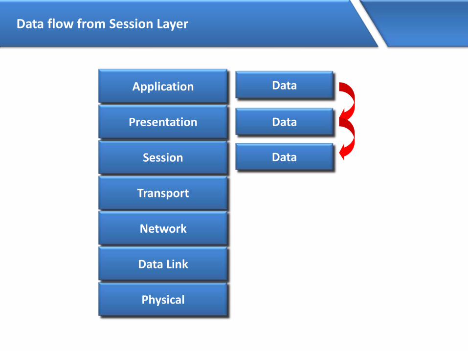
Data flow from Session Layer
Physical
Application
Session
Transport
Network
Data Link
Presentation
Data
Data
Data

Transport Layer
Transport Layer
It provides data delivery mechanism between the applications in the network.
The major functions described at the Transport Layer are..
•Identifying Service
•Multiplexing & De-multiplexing
•Segmentation
•Sequencing & Reassembling
•Error Correction
•Flow Control
Application
Presentation
Session
Transport
Network
Data Link
Physical
Transport

Identifying a Service
• Identification of Services is done using port Numbers.
• Port is a logical communication Channel
Total No. Ports 0 – 65535
Reserved Ports 1 - 1023
Open Ports 1024 – 65535

Multiplexing & De-multiplexing
TCP - 6 UDP - 17
2180 25 6753 69
Transport
Network
Data Link
Physical
Session
Presentation
Application

Transport Layer Protocols
• The protocols which takes care of Data Transportation at Transport layerare…TCP,UDP
TCP
• Transmission Control
Protocol
• Connection Oriented
• Supports Ack’s
• Reliable communication
• Slower data Transportation
• Protocol No is 6
• Eg: HTTP, FTP, SMTP
UDP
• User Datagram Protocol
• Connection Less
• No support for Ack’s
• Unreliable communication
• Faster data Transportation
• Protocol No is 17
• Eg: DNS, DHCP, TFTP

Segmentation
HELLO! HOW
ARE YOU?HELLO! HOW ARE YOU ?
Data

Sequencing
HELLO! HOW
ARE YOU?HELLO! HOW ARE YOU ?
Data

Sequencing
HELLO!HOW ARE YOU?

Sequencing
HELLO!1/5
HOW2/5
ARE3/5
YOU4/5
?5/5
Data

Sequencing
HELLO!1/5
HOW2/5
ARE3/5
YOU4/5
?5/5
HELLO!1/5
HOW2/5
ARE3/5
YOU4/5
?5/5

Data flow from Transport Layer
Physical
Application
Presentation
Session
Transport
Network
Data Link
Data
Data
Data
DataTHSegment

Network Layer
Network Layer
It provides Logical addressing & Path determination (Routing)
The protocols that work in this layer are:
Routed Protocols:
IP, IPX, AppleTalk.. Etc
Routed protocols used to carry user data between hosts.
Routing Protocols:
RIP, OSPF.. Etc
Routing protocols performs Path determination (Routing).
Application
Presentation
Session
Transport
Network
Data Link
Physical
Network

Data flow from Network Layer
Application
Presentation
Session
Transport
Network
Data Link
Physical
Data
Data
Data
DataTHSegment
SegmentNH Packet
Device that works at Network Layer is Router

Datalink Layer
Datalink Layer
It has 2 sub layers
• MAC (Media Access Control) It provides
reliable transit of data across a physical link.
It also provides ERROR DETECTION using CRC
(Cyclic Redundancy Check)
Ex: Ethernet, Token ring…etc
• LLC (Logical Link Control)
It provides communication with Network layer.
Application
Presentation
Session
Transport
Network
Data Link
Physical
Data Link

Data flow from Data link Layer
Application
Presentation
Session
Transport
Network
Data Link
Physical
Data
Data
Data
DataTHSegment
SegmentNH Packet
DT Packet DHFrame
Devices that work at Data link layer are Switch, Bridge etc..

Physical Layer
Physical Layer
It defines the electrical, Mechanical & functional
specifications for communication between the
Network devices.
The functions described at this layer are..
Encoding/decoding:
It is the process of converting the binary data into
signals based on the type of the media.
Copper media : Electrical signals of different voltages
Fiber media: Light pulses of different wavelengths
Wireless media: Radio frequency waves
Application
Presentation
Session
Transport
Network
Data Link
PhysicalPhysical

Data flow from Physical Layer
Application
Presentation
Session
Transport
Network
Data Link
Physical
Data
Data
Data
DataTHSegment
SegmentNH Packet
DT Packet DHFrame
Bits
Devices that work at physical layer are ..Hub, Repeater.. Etc

Comparison between OSI & TCP/IP Model
Application
Presentation
Session
Transport
Network
Data Link
Physical
Application
Host to Host
Internet
Network Access


