16
Bosch Stand-Alone TCD (Telemetry Communications Device) Installation Guide For alarm control panels using up to 16 pins, RS232, RS485 and dial capture

Bosch Stand-Alone TCD (Telemetry Communications Device)
Installation GuideFor alarm control panels using up to 16 pins, RS232, RS485 and dial capture

2
This guide sets out a simple check list together with a step-by-step guide to the components, installation, commissioning and fault finding for the Telemetry Communications Device; the gateway to the Emizon 21 service.
Introduction 2
Key Features 2
Check List 3
TCD Components 4
Step-by-Step Guide 5-8
Signal Strength Indicator 9
Fault Finding 10
Glossary 11
Compliance 12
Welcome to Bosch Stand Alone TCD
3
4
Bosch Stand Alone TCDEmizon 21 is the first secure, dual path, managed messaging service for IP networks. It means that your customers can now embrace the benefits of the IP era while maintaining the high standards associated with traditional dual path managed signalling services.
Key Features:
Secure
u Dual path service; broadband (primary) and GPRS
u EN Grade 4 signalling compliant
u Full audit trail on both paths
Easy to Install
u No on-site configuration
u Fits into existing panels
u Not site specific
Cost effective
u No connection charge
u No call charges
u Avoids need for a dedicated PSTN line
Future Proofed
u Designed specifically for IP networks
u Ready for BT’s 21CN deployment
Introduction

5
1. Check the Router Port ConnectionThe Ethernet port on the TCD simply plugs into a spare Ethernet port on the router in the customers’ premises using a standard Ethernet cable. Check that there is a spare port and that you have enough Ethernet cable to reach. Additional ports can be made available by using an Ethernet hub - available from IT suppliers who also supply Ethernet cable lengths.
2. Check Wireless GPRS Signal StrengthOperating in the same way as any GSM device, the GPRS module requires sufficient signal strength to communicate. For an easy indication of signal strength place a Vodafone mobile next to the panel – 2 bars or more is usually sufficient. For a more accurate indication see Step 6 which shows how to use the in-built diagnostic capability to display signal strength in a range from 0 to 31. Extension antenna cables can be used to provide additional signal strength away from the panel location. These are available from DG Systems on: 01530 815650 Fax: 01530 510625 email: [email protected]
u 3 Meters mmcx male to mmcx female part no. ex3/174cx
u 5 Meters mmcx male to mmcx female part no. ex5/174cx
3. Power-Down the Control PanelAs with the process for installing any type of alarm communications within a panel (Digi/STU) the panel must be:
u Out of commission, having notified your ARC
u Powered down, with the battery disconnected
Note: The TCD requires up to 450mA from the panel power supply.
4. Protect Against Static ElectricityTo protect the electrical components of the TCD from static electricity we recommend that you are earthed whenever you handle the equipment using a wrist strap and a 1M resistor.
5. Make a Note of the TCD Serial NumberDuring the commissioning process, you will need to relay this number to your ARC so that this can be matched against the customer installation number. Make a note of the serial number shown on the TCD label and box before you start and have this number ready!
Check List – Before you Start
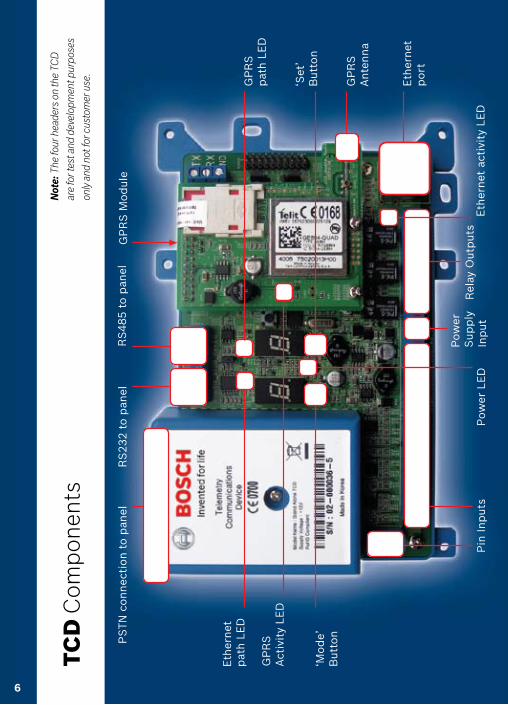
TCD Components
PS
TN c
onnec
tio
n t
o p
anel
RS
232 t
o p
anel
RS
485 t
o p
anel
Eth
ernet
p
ath L
ED
GP
RS
pat
h L
ED
GP
RS
Act
ivit
y LE
D
‘Mo
de’
But
ton
‘Set
’B
utto
n
Pin
Inp
uts
Pow
er
Sup
ply
In
put
Rel
ay O
utp
uts
Eth
ernet
p
ort
Eth
ernet
act
ivit
y LE
DP
ower
LE
D
GP
RS
Ante
nna
TCD
Com
pon
ents
N
ote:
The
four
hea
ders
on
the
TCD
are
for t
est a
nd d
evel
opm
ent p
urpo
ses
only
and
not
for c
usto
mer
use
.
GP
RS
Mo
dul
e
6

7
Step 1: Fit the TCD in the Alarm Control Panel
u Position the TCD in the panel and fix in place using either the sticky pads supplied or your own screws.
u Mount the antenna on top of the alarm panel box (wait till Step 6 to affix in place) and run the wire down the back of the panel and connect to the antenna connector.
u Connect the Ethernet port to the router in the customer’s premises.
Connect to spare port on Router
Mount antenna on the top face of the panel
Connect antenna
Step-by-Step Guide
Router

Step-by-Step Guide
8
Alarm Panel
Panel Outputs
Step 2: Connect TCD to the Panel
u Connect the TCD pin inputs to the panel
u Connect the power supply to the TCD power supply input, carefully observing the correct polarity
Panel Inputs
Panel control board
Panel powersupply board
TCD Connection To Alarm Panel Using Pins

Step-by-Step Guide
9
Step 3: Connect and Check Relays
The three relays are positioned next to the Ethernet port are:
u Control Output – Controlled by the ARC and used for various purposes such as resetting the alarm panel following an event.
u Line Fault – Activated when the TCD is unable to transmit a message. This relay can also be programmed to operate the Form 175 function.
u RPS – Return Path Signalling – When this function is enabled, the RPS u relay activates whenever any alarm is being transmitted, and is reset only u when there are no alarms waiting to be acknowledged by the ARC.
Each relay is a changeover type with a common Normally Open and Normally closed terminal. The contacts are rated at 30VDC @ 1A.
Control Output Relay Line Fault Relay Return Path Signalling (RPS) Relay

Step 4: Boot up and Signalling Check Turn on the power supply to the panel, wait 15 secs (approximately):
u The power status RED LED will illuminate. The Ethernet and GPRS activity LEDs will flicker. The path LEDs will illuminate briefly and then extinguish.
u If this is the first time this TCD is being installed, you will need to wait for the ‘t l’ indication to appear on the display, and then press and hold the Set button and Mode buttons together for 10 seconds, the TCD will make contact with the Emizon Service Platform and download the latest firmware. If ‘r r’ is displayed then a firmware update has taken place – please power off and power on the TCD.
10
Upon boot, the following display codes are shown.
The following display codes are shown. c101 aE
6 U 1C6Boot Up Boot Complete TCD Initial State
Step 5: Commissioning with your ARC
u Call your ARC with the TCD serial number printed on the label on the front cover. The ARC will then ‘associate’ or link the TCD to this specific installation on their system and ‘activate’ it. u Press the ‘set’ button for 5 seconds.
u The user display will then alternate between ‘t 1’ and ‘0 1’ then ‘C A’ (completely activated) indicating a successful commission. The GPRS and Ethernet path LEDs will change to green to indicate that they are communicating with the Emizon Service Platform.
u For added security there is a time out period of around 20 minutes for ARC activation.
Note: if you re-power the TCD you will need to repeat the ARC commissioning process.
E
Step-by-Step Guide
11
Step 6: System Test
u Following the successful activation you can then test the move to test all alarms on both signalling paths ensuring that the alarm panel is ready for service.
u Once this is complete, affix the aerial in place on top of the panel.
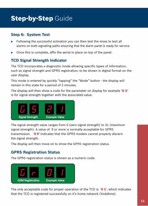
TCD Signal Strength IndicatorThe TCD incorporates a diagnostic mode allowing specific types of information, such as signal strength and GPRS registration, to be shown in digital format on the user display.
This mode is entered by quickly “tapping” the “Mode” button - the display will remain in this state for a period of 2 minutes.
The display will then show a code for the parameter on display for example ‘G S’ is for signal strength together with the associated value.
The signal strength value ranges from 0 (zero signal strength) to 31 (maximum signal strength). A value of 9 or more is normally acceptable for GPRS transmission. ‘9 9’ indicates that the GPRS modem cannot properly discern the signal strength.
The display will then move on to show the GPRS registration status.
GPRS Registration Status The GPRS registration status is shown as a numeric code:
The only acceptable code for proper operation of the TCD is ‘0 1’, which indicates that the TCD is registered successfully on it’s home network (Vodafone).
Step-by-Step Guide
g s 12Signal Strength Example Value
g 8 1oGSM Registration Example Value

12
Step 7: Fault Finding
The TCD comes with in-built fault finding capability. When detected, Error and Fault conditions are displayed on the user interface display using the convention of ‘E’ for non-fatal errors and ‘F’ for faults requiring Bosch intervention. The display will also show a number code to indicate the nature of the problem.The three most common error codes together with the potential reasons and solutions are shown on the table below:
Error Code Possible Reason and Solution
For help and advice with any other error or fault code displayed contact the
Bosch Technical Line: 01895 878088
Step-by-Step Guide
F 0Fault Code 0: Configuration read from flash failed – device is faulty please replace with a new TCD
E 0Error Code 0: IP path not connected. Check Ethernet cable from TCD to socket. Make sure connectivity to router is completed – if DHCP is not enabled a static IP address is required.
E 1Error Code 1: Unable to contact Emizon Service Platform for configuration parameters. Check IP path is continuous to customers router (is Green light flashing on Ethernet port on TCD?).

13
Glossary
Term Description
BT 21CN BT’s £10bn programme to upgrade the analogue network to their next generation IP infrastructure called BT 21st Century Network or 21CN. The programme has implications for many traditional signalling systems.
Commissioning Process to ensure that the alarm panel is recognised and can communicate on both paths with the ARC across the Emizon Service Platform.
DHCP Dynamic Host Configuration Protocol. Allows a device i.e. the alarm control panel to automatically request and obtain an IP address.
Ethernet hub Device that is used with a router to extend the number of ports or connections available to the IP network.
Ethernet port Connection point on a router .
GPRS module Provides connectivity for the secondary GPRS communications path for Emizon 21 on the TCD.
Installation An individual customer premise connected to the Emizon 21 service via the hardware or TCD (Bosch equivalent of a Digi or STU) in the alarm panel.
IP Address Internet protocol. A number that identifies each sender or receiver of information that is sent in packet across the Internet.
IP module Provides connectivity for the primary IP/Broadband communication path for Emizon 21 on the TCD
Router Provides the gateway at the customer’s premises into the global IP network and the benefits that it brings. It is the router that enables the alarm control panel to communicate with the Emizon platform and then onwards to the ARC.
TCD serial number The unique reference number for the TCD. This number allows the alarm equipment at the customer’s premises to be matched against the installation number on the ARC’s data base as well as on the Emizon Service Platform.

14
The TCD complies with the requirements of the European EMC Directive (89/336/EC), the Low Voltage Directive (72/23/EC and 93/68/EC) & from (1/1/2006) the “Reduction of Hazardous Substances Directive (2002/95/EC)
Appropriate components also comply with the requirements of the R&TTE directive (1995/5/EC). EN55022 Emissions Class B. EN50130-4 Immunity. And 89/336 Electro Magnetic Compatibility Directive) as amended by 92/31/EEC.
Signalling ComplianceEmizon 21 is suitable for installation in systems complying with EN 50131-1 at: Security Grade 4.
Environmental ComplianceEnvironmental Class 2
Warranty Bosch will repair or replace, at our discretion, any Stand-Alone TCD developing a fault within 12 months, free of charge. Products for repair should be returned to Bosch suitably packed to prevent damage (including any damage from electrostatic discharges), and be accompanied by full details of the fault and the full return address.
DisposalThe symbol shown here and on the product, means that the product is classed as Electrical or Electronic Equipment and should not be disposed of with other household or commercial waste at the end of its working life.
The Waste Electrical and Electronic Equipment (WEEE) Directive. (2002/96/EC) has been put in place to recycle products using the best available recovery and recycling techniques to minimise the impact on the environment, treat any hazardous substances and avoid the increasing landfill.
Product Disposal Instructions for Residential Users:When you have no further use for it, please dispose of the product as per your local authority’s recycling processes.
For more information, please contact your local authority or retailer where the product was purchased.
Compliance

Contact details
Bosch Security Systems LtdNorth Orbital RoadDenhamUxbridgeUB9 5HJ
Help Desk Tel: 01895 878093
Opening Hours9am - 5pmMonday to Friday
E-mail:[email protected]
Websitewww. boschsecurity.co.uk
Bosch reserves the right to adjust specifications of this system and information contained in this manual, at any time and without notice, in the interests of product improvement.
(Version 1 - 01 July 2007)
15
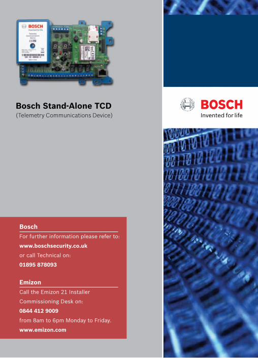
Bosch Stand-Alone TCD (Telemetry Communications Device)
Bosch
For further information please refer to:
www.boschsecurity.co.uk
or call Technical on:
01895 878093
Emizon
Call the Emizon 21 Installer
Commissioning Desk on:
0844 412 9009
from 8am to 6pm Monday to Friday.
www.emizon.com


