696
COMBINED AQUATICS STUDY PLANS CAWG-2-GEOMORPHOLOGY

COMBINED AQUATICS STUDY PLANS
CAWG-2-GEOMORPHOLOGY
Copyright 2003 by Southern California Edison Company CAWG-2-i September 2003
TABLE OF CONTENTS
PAGE
CAWG-2 Geomorphology ............................................................................................... 11.0 Executive Summary.............................................................................................. 12.0 Study Objectives................................................................................................... 73.0 Study Implementation........................................................................................... 83.1 Study Elements Completed .................................................................................. 83.2 Outstanding Study Elements .............................................................................. 104.0 Study Methodology............................................................................................. 134.1 Review and Analyze Existing Data ..................................................................... 134.1.1 Watershed and Reach-Scale Characteristics ..................................................... 134.2 Aerial Reconnaissance Surveys ......................................................................... 164.3 Ground Reconnaissance Surveys ...................................................................... 184.3.1 Channel Entrenchment, Valley Confinement, Bed Form, and ChannelClassification ................................................................................................................ 204.3.2 Particle Size and Depositional Features............................................................. 204.3.3 Large Woody Debris (LWD)................................................................................ 214.3.4 Bank Stability...................................................................................................... 214.3.5 Vegetation Encroachment .................................................................................. 214.3.6 Description of Channel Bars ............................................................................... 224.3.7 Tributary Inputs................................................................................................... 224.3.8 Sediment Sources and Deposits ........................................................................ 224.3.9 Additional Comments and Observations ............................................................ 225.0 Study Results and Analysis ................................................................................ 235.1 Watershed Characteristics ................................................................................. 235.1.1 Geology .............................................................................................................. 235.2 Channel Morphology .......................................................................................... 275.2.1 Rosgen Level 1.0 Classification and Reference Reach Assessment ................. 275.2.2 Rosgen Level 1.5 Classification.......................................................................... 275.2.3 Results of Rosgen Level 1.5 Classification of Project-Affected Streams ............ 315.2.4 Floodplain/Terrace Connectivity ......................................................................... 395.2.5 Potential Riparian Encroachment ....................................................................... 435.2.6 Large Woody Debris (LWD) and Function.......................................................... 46

Combined Aquatics Working Group CAWG-2 Geomorphology
Copyright 2003 by Southern California Edison Company CAWG-2-ii September 2003
5.2.7 Montgomery Buffington Classification ................................................................ 505.2.8 Sensitive Channel Types.................................................................................... 545.3 Sediment Supply and Sediment Transport Characteristics ................................ 585.3.1 Sediment Sources .............................................................................................. 595.3.2 Tributaries........................................................................................................... 685.3.3 In-Channel Sediment Storage and Sand and Gravel Accumulation ................... 705.3.4 Conceptual Framework for Sediment Transport ................................................. 795.4 Overview of Quantitative Study Recommendations............................................ 846.0 Literature Cited ................................................................................................... 88
Copyright 2003 by Southern California Edison Company CAWG-2-1 September 2003
CAWG-2 GEOMORPHOLOGY
1.0 EXECUTIVE SUMMARY
Sediment supply in the Project area watershed is primarily from three sources: (1)debris flows in the steep-gradient headwater channels that are tributary to the mainstemrivers; (2) rockfalls in exposed jointed bedrock along the inner gorges of the SanJoaquin River (SJR), the lower-half of the South Fork San Joaquin River (SFSJR) (RiverMile (RM) 0.0 to 14), and along portions of Big Creek; and (3) sheetwash erosion thatdelivers sand which is widespread throughout the watershed. Other hillslope erosionprocesses including gullies, rills, and landslides were rarely observed in the watershed,although there are well-forested areas along many non-project streams that could notbe inspected during aerial reconnaissance where some of these sediment productionprocesses may be operative. It was noted during the aerial reconnaissance that themainstem SJR upstream from the confluence with the South Fork, transports sand andgravels (GIS Map 3, Data Set 2, Figure CAWG-2-6c, and Section 5.3.3 In-ChannelSediment Storage and Sand and Gravel Accumulation).
Bank erosion is not a significant sediment production process on project affectedstreams, and the vast majority of streams are laterally stable. Project affected streamswere characterized as having either erodible or non-erodible streambanks. Non-erodible streambanks comprise approximately 77% (71.2 miles) of the total channellength surveyed downstream of project facilities. Locations of erodible and non-erodiblestreambanks are mapped. The largest area of potentially erodible streambanks (i.e.,does not necessarily mean that streambanks are actively eroding) is along mostsections of the SFSJR downstream from Florence Lake, between RM 14 and 27.7.Locations of lateral stream instability are mapped. Most of these unstable locations areassociated with channels that cross alluvial debris fans, including Hooper, North andSouth Slide, Tombstone, Chinquapin, and Bolsillo Creeks. Lateral instability on thesechannels is expressed as channel avulsion and the formation of multiple channels, andprobably occurs episodically whenever there is a debris flow. Lateral instability is alsoindicated for a section of North Fork Stevenson Creek (RM 1.8 to 2.4), in a reach thatappears to have aggraded due to excess sediment supply (GIS Maps, Data Set 1 Map1 Figure CAWG-2-3a, Data Set 2, Map 1 Figure CAWG-2-6a, Section 5.2.3, andSection 5.3.3 In-Channel Sediment Storage and Sand and Gravel Accumulation).
Gravel sources are predominantly from those basins that contain a large proportion ofglacial till. These areas have been previously mapped by the California Division ofMines and Geology, and this mapping was supplemented by observations of glacial tilllocations during the aerial surveys. Glacial till locations are presented in the GeologySection of this report. The total area of glacial till in the SJR basin upstream fromKerckhoff Lake represents approximately 9% of the total lithology. Project tributaries tothe SFSJR below Florence Lake proportionally contain the largest areas of glacial till,typically 40% or more of their respective drainage areas. In terms of absolute area,Mono Creek upstream from the Mono Creek diversion and Big Creek upstream from
Combined Aquatics Working Group CAWG-2 Geomorphology
Copyright 2003 by Southern California Edison Company CAWG-2-1 September 2003
Huntington Lake encompass the largest glacial-till areas. Most of the glacial till areasdrain to Huntington Lake, Edison Lake, and the Mono Creek diversion.
Lower gradient, poorly entrenched and unconfined channels (for example, C and Echannel types) present the best opportunity for deposition of gravel bars. These channeltypes also provide suitable deposition sites for sand bars. The more moderatelyentrenched or moderate gradient channels (B and G channel types) tend to have cobbleand boulder bars mixed with gravels, or poorly-sorted, gravels scattered on the bed.These channel types can also express well-sorted gravel deposits in smaller areas suchas the velocity shadows created by boulders and bedrock outcrops. Higher gradientchannels and bedrock channels (A1a, A1a+) tend to have few, scattered gravel depositsin pools or no deposits at all due to their high transport capacity.
Streams that drain proportionately large areas of glacial till within their basins but havechannel morphologies that generate high transport capacities, tend to have scattered,poorly sorted gravel “deposits”, that are typically mixed with a wide range of otherparticle sizes. North Slide, South Slide, Hooper, Bolsillo, Camp 62, and Chinquapin allhave greater than 40% of their basins draining glacial till, but gravel deposits are notfound as well-sorted accumulations, probably due to their relatively steep-gradients andentrenched morphology. Gravels were also observed to accumulate as bars or otherwell-sorted deposits in drainage basins that have relatively smaller amounts of glacialtill, but have suitable deposition locations (ie, lower gradient and moderately entrenchedmorphology). Pitman Creek immediately upstream of the diversion is a good exampleof a short (approximately 1,000-ft long), but flat-gradient locale where well-sorted graveldeposits occur. Just upstream from these gravel deposits is a steeper, bedrockcontrolled reach with very few, and scattered gravel deposits. About 16% of the PitmanCreek drainage basin is comprised of glacial till. A description of the transport capacityof stream channels is provided in Section 5.3.4, Conceptual Framework for SedimentTransport.
In-channel sediment storage is discussed in Section 5.3.3 and locations of sedimentstorage are mapped. Of all the sand and gravel deposition sites, the following locationsare considered to be the most likely to represent an “excessive” condition and are themost extensive in area. It is cautioned that even from this list there may be sites onlyresponding to a natural, episodic cycle of sediment input and transport.
Mono Creek
• Sand deposits at 2 sites (RM 2.3 to 2.8 and RM 3.6 to 3.8)
San Joaquin River
• Sand accumulation immediately below the Willow Creek confluence
• Sand accumulation at the Shakeflat Creek confluence (RM 25.3 to 25.6)
Combined Aquatics Working Group CAWG-2 Geomorphology
Copyright 2003 by Southern California Edison Company CAWG-2-2 September 2003
• Sand accumulation in pools between Dam 6 and Redinger Lake (RM 12.6 to 13.0and RM 15.2 to15.6)
• Coarse sediment accumulation (mostly boulders) between Dam 6 and Powerhouse3
• Coarse sediment accumulation (mostly boulders and cobble) between Rock andRoss Creek
North Fork Stevenson Creek
• Gravel, cobble, and sand accumulations in the C3 and B3 classified reaches(RM 1.8 to 2.4)
Stevenson Creek
• Sand accumulation immediately below Shaver Dam (RM 3.8 to 4.2)
Big Creek
• Sand accumulation in locations upstream from Kerckhoff Dome (RM 8.0 to 10.0)
South Fork San Joaquin River
• Sand and gravel accumulation in the low-gradient channel section along JackassMeadow (RM 26.2 to 27.7)
Identifying “excessive” erosion and scour presents the same difficulties as defining“excessive” build-up of fine sediments. The following list identifies the most obvious andextensive locations of potentially excessive erosion and scour identified during thequalitative field study:
Stevenson Creek
• Channel incision immediately below Shaver Dam (RM 3.8 to 4.2)
North Fork Stevenson Creek
• Channel incision and widening immediately below Tunnel 7 outlet (RM 3.45 to 3.55)
• Bank erosion in the gravel, cobble, and sand accumulated C3 and B3 classifiedreaches (RM 1.8 to 2.4)
Deposition of material at tributary junctions was investigated for all project and manynon-project streams in the watershed. Very few tributary deposit locations wereidentified, the most notable of which were the Shakeflat and Willow Creek confluenceson the SJR. Both locations are also listed above as sand accumulation sites.
Combined Aquatics Working Group CAWG-2 Geomorphology
Copyright 2003 by Southern California Edison Company CAWG-2-3 September 2003
A conceptual framework describing sediment transport through the SJR channelnetwork is provided based on channel bed morphology. Bed morphology is in partformed by and linked to sediment supply and sediment transport characteristics.Project streams are organized into source, transport and response segments thatgenerally define their relative capacity to transport and store sediments at the reachscale.
In general, the steep-gradient, headwater streams tributary to the higher-ordermainstem channels (Big Creek, SFSJR, and SJR) are intimately connected to hillslopesediment production processes. Sediment supply from the steep tributary channelscollects in the headwater areas, and is episodically conveyed by debris flows. Some ofthe sediment supply is stored on alluvial fans or the valley floodplain, and must betransported by streambank erosion processes before entering the mainstem streams.
The Hooper and Chinquapin diversions interrupt transport and subsequent storage ofsediment from debris flow processes, reducing at least the coarse material loadnaturally delivered to the alluvial fan. However, a recent (1997) debris flow destroyedthe Chinquapin diversion facility, and the sediment supply from that event has clearlydeposited at the site of the old diversion, which has subsequently been rebuilt about ¼mile upstream. Since Tombstone, North and South Slide, and Adit 8 are inoperablethey do not alter the transport of sediments. These four facilities are not currentlydiverting flow and therefore, do not alter the natural flow regime, and additionally, theyare not collecting sediments since they have no sediment storage capacity behind theirdiversions. The other smaller diversion facilities on the tributaries to the SFSJR, BigCreek, and SJR including Crater Creek, Camp 62, Bolsillo, Balsam, Ely, Ross, andRock Creeks, all have relatively small sediment storage capacities and smaller diversiondams than either Hooper or Chinquapin. The high gradient tributaries arepredominantly step-pool, cascade, and bedrock channel types that are defined astransport channels. Coarse sediment tends to be stable in these channel types exceptfor infrequent large flood flows. Fine sediment is more regularly transported over thestable, large bed elements by frequently occurring annual floods. The mainstemchannels also collect coarse sediment (mostly boulders) derived from rockfalls alongbedrock valley walls of their inner gorges. Much of the coarse boulder material can bemoved only in the largest floods, or may not ever be transported.
A considerable portion of the mainstem SJR between Mammoth Pool and RedingerLake is designated as a response type channel; plane-bed and pool-riffle channelmorphology (Section 5.2.7 Montgomery-Buffington). The response channel type istypically a transport-limited stream (i.e. sediment supply exceeds the transportcapacity), and therefore tends to store sediments. In addition, the large rockfalls whichare not fluvially transported sediments, accumulate in long-term storage. This portion ofthe SJR is significantly confined by bedrock valley walls which is relatively unusual forplane-bed and pool-riffle channel types. The highly confined morphology increasesshear stress and therefore sediment transport capacity relative to an unconfinedchannel, and restricts channel responsiveness to alterations of the flow or sedimentregime (ie, channel dimensions and planform are resistant to alteration). Tributarychannels to the SJR, including Ross and Rock Creeks are transport reaches, indicative
Combined Aquatics Working Group CAWG-2 Geomorphology
Copyright 2003 by Southern California Edison Company CAWG-2-4 September 2003
of a bedrock channel morphology. These tributaries are supply-limited, having a muchgreater transport capacity than sediment supply.
The lower-half of the SFSJR is designated a transport reach (step-pool and plane-bedmorphology), and similar to the SJR, is highly confined by bedrock valley walls. Theupper-half of the SFSJR (from approximately Rattlesnake Crossing to Florence Lake) isa response type reach (plane-bed and pool-riffle channel morphology), but isunconfined by valley walls and has banks that could be erodible. Big Creek, except fora one-mile segment below Huntington Lake, is a steep-gradient transport reach(bedrock channel morphology), indicative of the supply-limited streams. The one milelong segment below Huntington Lake is a classified as a response reach, and there areindicators that this portion of the channel has aggraded and narrowed. Pitman Creek isalso a bedrock type transport channel. Most of Stevenson Creek and North ForkStevenson Creek is also a transport reach; bedrock, cascade, or step-pool morphology(Section 5.2.7 Montgomery-Buffington).
Large woody debris (LWD) accumulations were identified and mapped. Generally,more woody debris was observed on the well-forested, narrow, and steep-gradienttributary channels to the SFSJR and tributaries to Big Creek than at other projectstream locations. Mono Creek was observed to have more extensive areas withaccumulations of LWD than all other project streams.
LWD had no geomorphic function in the larger streams with large roughness elements,for example on the San Joaquin River and South Fork San Joaquin River (Section 5.2.6Large Woody Debris). In-channel LWD was often observed lying over the top ofboulders and did not appear to interact with stream flow. In moderate to steep gradientstreams with boulder and bedrock substrates LWD had little opportunity to influencechannel morphology. In those instances when a geomorphic function was observed, itwas typically related to facilitating storage of fine sediments behind debris jams orcreating dammed pools. LWD was identified collecting at the Bear Creek and MonoCreek diversions, and at the inlet to Mammoth Pool.
Several potential floodplain areas were identified and mapped, and their observedconnectivity to the channel was characterized whenever possible. Further hydrologicdata and analysis is necessary in order to better estimate how floodplain connectivity(i.e., frequency and extent of overbank flows) may be influenced by project diversions.Most of the project channels do not have a floodplain (as defined by criteria in thisstudy), because they are highly entrenched channels, that is A, and G channel typesthat by definition do not have floodplains. Some of the B-channel types have, andothers do not have, a floodplain (Section 5.2.4 Floodplain Connectivity).
Streams with segments that have potential floodplain areas include:
• North Fork Stevenson Creek (RM 1.7 to 2.4)
• Stevenson Creek (RM 3.9 to 4.3)

Combined Aquatics Working Group CAWG-2 Geomorphology
Copyright 2003 by Southern California Edison Company CAWG-2-5 September 2003
• Big Creek (RM 8.3 to 8.6)
• SFSJR (RM 14.0 to 24.1 and RM 26.1 to 27.7)
• Crater Creek (RM 0.0 to 0.7)
• Tombstone Creek (RM 0.0 to 0.5)
• Mono Creek (RM 2.3 to 2.8, and RM 3.5 to 3.7)
Riparian vegetation within and along the margins of the bankfull channel wascatalogued, identifying those areas considered to be potentially encroached. Given thatthe 2002 field surveys were qualitative in nature, for purposes of this studyencroachment is referred to as potential encroachment. Designations of potentialencroachment, at this time, are not definitive statements of an encroached condition.
Potential channel encroachment by riparian vegetation was classified into one of twoprimary groups: 1) dense and continuous; and 2) limited and discontinuous. The twogroups encompass the widely differing extent of potential encroachment conditionsobserved in the field. Locations identified as dense and continuous riparianencroachment are listed below. There were several areas identified under the limitedand discontinuous encroachment category, notably on the SFSJR below Florence Lake,a portion of Big Creek, and a portion of Mono Creek, as well as a few other scatteredlocations. Both categories of potential riparian encroachment are depicted on maps inthis report. The appearance of vegetation extensively colonizing infrequent and widelyspaced bars, or mature riparian vegetation growing on colluvial deposits at the toe of asteep gradient hillslope within the estimated historic bankfull elevation, or adiscontinuous “band” of vegetation within the estimated historic bankfull elevationgrowing along the channel margin, were all identified as potentially encroachedconditions in this report. Photographs are provided in the Potential RiparianEncroachment section depicting both categories of encroachment as recognized in thisstudy.
Locations of Dense and Continuous Potential Encroachment
• Stevenson Creek below Shaver Dam, there is a 0.4 mile reach (RM 3.9 to 4.3)
• Big Creek, immediately downstream of Huntington Lake (RM 8.0 to 9.6)
• Mono Creek from RM 1.35 to 4.05
• Bolsillo Creek immediately downstream from diversion (RM 1.47 to 1.57)
Channel geomorphic classifications based on Rosgen and on Montgomery-Buffingtonwere performed for all project streams (Sections 5.2.6 and 5.2.7, respectively), and arepresented as maps in this report (Figures CAWG-2-3a, 3b, 3c, 3d, CAWG-2-8a, 8b, 8c,and 8d). These geomorphic classification systems were used to describe channel
Combined Aquatics Working Group CAWG-2 Geomorphology
Copyright 2003 by Southern California Edison Company CAWG-2-6 September 2003
morphology (Section 5.2 Channel Morphology), develop the conceptual framework forsediment supply and sediment transport in the watershed (Section 5.3.4 ConceptualFramework for Sediment Transport), to identify sensitive channel types (Section 5.2.8Sensitive Channel Types) and describe the probable range of channel responses toproject operations (Section 5.2.8).
The following channel types and the total project stream miles associated with eachchannel type that are most responsive to project operations, include:
• Pool-riffle (7.6 miles)
• Plane-bed/pool-riffle (15.8 miles)
• Plane-bed (11.9 miles)
Using the Montgomery-Buffington classification and criteria for sensitive channel types,which is the most conservative approach (i.e., most inclusive of responsive channeltypes compared with the Rosgen classification), a total of approximately 35 miles ofproject streams (39%) are recognized as potentially sensitive to project operations. Thesensitive plane-bed and pool-riffle channel types are mapped in this report as part of theMontgomery-Buffington classification. The majority of project streams (61%) are notconsidered to be channel types particularly responsive to changes in the flow orsediment regime. The Montgomery-Buffington classification system can be used topredict reach-scale channel responses to changes in the flow or sediment regime,although the predictive capability of the classification system does have limitations,including addressing the magnitude of changes at a smaller, habitat-unit scale.
The majority of the potentially sensitive channel types are located on the SJR betweenRedinger Lake and Mammoth Pool (16.8 miles) and SFSJR between Florence Lake andRattlesnake Crossing (10.8 miles), in addition to a few shorter reaches of Big Creek andMono Creek. Almost all of the SJR sensitive channel reach is highly confined by steepvalley, mostly non-erodible bedrock walls. Channel confinement exerts an importantcontrol on potential channel response, as channels with wide floodplains (i.e. poorlyconfined) may laterally shift, change their sinuosity or planform in response todisturbance (Montgomery and MacDonald 2002) and highly confined channels can haveonly a limited response, reducing their sensitivity to alterations of the flow and sedimentregime (Montgomery and MacDonald 2002; and Montgomery and Buffington,1997).The most likely response of the highly confined sensitive channel reach in the SJR is achange in particle size or sediment storage.
A less conservative approach to identifying sensitive channels, based in part on theRosgen classification and study results from other fluvial geomorphologists, identify thefollowing channel types and their respective total lengths, as sensitive:
• B3, B4, B5 (8.5 miles)
• C3, C4, C5 (2.9 miles)
Combined Aquatics Working Group CAWG-2 Geomorphology
Copyright 2003 by Southern California Edison Company CAWG-2-7 September 2003
• DA (accounted for under the E5/DA5 channel type)
• E3, E4, E5 (.9 miles)
• G3, G4, G5 (2.5 miles)
The C and E channel types listed above are found primarily on the SFSJR at Mono HotSprings, the lowermost 0.5 mile Crater Creek and 0.5 mile of Tombstone Creek near theconfluence with the SFSJR, and a section of North Fork Stevenson Creek upstreamfrom the Eastwood Powerhouse. The B3, B4, and B5 channel types are found onseveral project streams, including SFSJR between Florence Lake and Rattlesnakecrossing, on Mono Creek downstream of Mono Meadow, Big Creek between KerkhoffDome and Huntington Lake, North Fork Stevenson upstream from EastwoodPowerhouse, and Stevenson Creek immediately below Shaver Lake. In addition, thereare numerous shorter channel segments (less than 1,000 ft lengths) of B channel typeson the tributary channels to Big Creek and to the SFSJR that are found betweensteeper gradient A-type channel segments. The G3, G4, G5 channel types arepredominantly found in the lowermost reach of the SJR, just downstream of RedingerLake.
Using this approach, there is approximately 14.8 miles of sensitive project channels. Allof the sensitive channels based on Rosgen classification are included within theMontgomery-Buffington classification.
2.0 STUDY OBJECTIVES
The objective of the CAWG-2 study is to determine the effect of flows on thegeomorphology of Project-affected streams and impoundments. The CAWG-2 studyplan includes the following objectives:
• Determination of sediment conditions and sediment transport requirements;
• Evaluation of sediment sources (including tributaries) and conditions;
• Identification and mapping of major sediment deposits;
• Evaluation of stream channel stability;
• Comparison of unimpaired and Project-affected sediment regimes;
• Evaluation of the timing, magnitude, and duration of unimpaired and Project-affectedflows in relation to geomorphic effects;
• Quantification and characterization of sediment volume and grain size variation inProject reservoirs and impoundments;
• Characterization of the effects of existing sediment management actions and LargeWoody Debris (LWD) management;
Combined Aquatics Working Group CAWG-2 Geomorphology
Copyright 2003 by Southern California Edison Company CAWG-2-8 September 2003
• Determination of whether the presence and amount of woody debris in Project-affected reaches is within the range of natural variability;
• Determination of the functionality of riparian habitat;
• Determination of the effects of potential PM&Es on fluvial geomorphology; and
• Determination of the effect of the Project on fluvial geomorphological features.
3.0 STUDY IMPLEMENTATION
This section describes the CAWG-2 Study Plan elements completed during 2002 andidentifies the outstanding study elements to be completed in 2003. The study plan isdivided into six sequential steps with specific information to be collected and evaluatedduring each step. This section is organized to follow each step and describe theelements completed or outstanding for each step.
3.1 STUDY ELEMENTS COMPLETED
A description of the CAWG-2 Study Plan elements that were completed during 2002 isprovided below and summarized in Table CAWG-2-1.
Step 1: Review and Analyze Existing Data− Reviewed existing information and developed a conceptual framework for the
sediment transport regime within the Big Creek system. The methods utilized inthis step are described in Section 4.1 and the information obtained isincorporated into the discussion of the sediment supply and transportcharacteristics presented in Section 5.3.
− Reviewed existing aerial photography and maps. The methods utilized in thisstep are described in Section 4.1 and the information obtained was used inconjunction with the data collected during the aerial and ground reconnaissancesurveys to describe the watershed characteristics and channel morphology aspresented in Sections 5.1 and 5.2, respectively.
− Developed Rosgen (1996) Level I classification for project streams. The methodsutilized in this step are described in Section 4.1 and the information obtained wasused in conjunction with the data collected during the aerial and groundreconnaissance surveys to describe the channel morphology as presented inSection 5.2.
Step 2: Qualitative Reconnaissance Field Survey of the Study Area− Developed field data sheets that were submitted and approved by the Combined
Aquatic Working Group (CAWG) in June 2002.

Combined Aquatics Working Group CAWG-2 Geomorphology
Copyright 2003 by Southern California Edison Company CAWG-2-9 September 2003
− Conducted aerial and ground reconnaissance surveys to describe existinggeomorphic and sediment conditions and characterize parameters useful inassessing the effects of Project-flow regimes on the streams’ ability to maintaindynamically stable, functional channels. The methods utilized in this step aredescribed in Sections 4.2 and 4.3 and the information obtained was used todescribe the channel morphology as presented in Section 5.2.
− Mapped floodplain and wetland areas, including abandoned floodplains(terraces) in all Project-affected reaches. The methods utilized in this step aredescribed in Sections 4.2 and 4.3 and the information obtained was used todescribe the channel morphology as presented in Section 5.2.
− Transferred and stored data in GIS format.
− Documented ground reconnaissance surveys with photographs. A compilation ofthe photographs collected during the surveys is provided in Appendix A.
− Evaluated potential reference areas in adjacent tributaries and sub-basins duringthe Rosgen Level I analysis described in the Watershed and Reach-ScaleCharacteristics section. The results of this evaluation were distributed in digitalformat to the CAWG in June 2002 (SCE Big Creek ALP Level I GeomorphicClassification and Candidate Reach Assessment, June 2002). The Level Ianalysis results are presented in Appendix B of this report.
• Step 3: Data Synthesis and Interpretation for Presentation to the CAWG
− Describe the overall sediment transport regime in the relicensing basin, andwithin each Project-related stream and reservoir. The sediment transport regimeis described in Section 5.3 of this report. This description will be updated toinclude information related to SCE sediment maintenance practices at projectfacilities following the completion of the quantitative studies in 2003.
− Use field data and observations in conjunction with existing information ongeology, soils, hydrology, and Project operations to evaluate the balancebetween sediment input to the channels, and their capacity to transport thissediment at current flows. A description of the sediment supply and sedimenttransport characteristics is provided in Section 5.3 of this report. This descriptionwill be updated based on the results of the hydrologic analysis and roadassessment following completion of the quantitative studies in 2003.
− Use field channel morphology data and hydrological analyses (Step 1) inconjunction with information on riparian vegetation, floodplains and wetlands, toassess the relationship of in-channel and overbank flow frequency, magnitude,and duration. A description of floodplain/terrace connectivity is provided inSection 5.2.3 of this report and a discussion of riparian encroachment is providedin Section 5.2.4 of this report. These descriptions will be updated following thecompletion of the quantitative studies in 2003.
Combined Aquatics Working Group CAWG-2 Geomorphology
Copyright 2003 by Southern California Edison Company CAWG-2-10 September 2003
− Describe the type, quality, and limitations of available reference conditions for allproject-affected reaches. This information was provided in digital format to theCAWG in June 2002 (SCE Big Creek ALP Level I Geomorphic Classification andCandidate Reach Assessment, June 2002). The Level I analysis results arepresented in Appendix B of this report.
3.2 OUTSTANDING STUDY ELEMENTS
A description of the CAWG-2 Study Plan elements that remain to be implemented in2003 is provided below and summarized in Table CAWG-2-1.
Step 1: Review and Analyze Existing Data
− A determination of the timing, magnitude, and duration of geomorphically-significant and riparian/floodplain flows by analyzing hydrologic records andperforming flood-frequency analyses (Leopold, et al., 1964).
− Additional review of ground and aerial photographs to specifically include historicphotos of Florence Lake.
Step 2: Qualitative Reconnaissance Field Survey of the Study Area
− An evaluation of the potential for sediment delivery to the channel from upsloperoads, based on the approach of Weaver and Hagans (1994), or similar USFSmethod.
− Additional analysis of potential delivery of sediment from tailings/spoils pilesassociated with the project.
Step 3: Data Synthesis and Interpretation for Presentation to the CAWG
− An assessment of the relationship of in-channel and overbank flow frequency,magnitude, and duration using field channel morphology data and hydrologicalanalyses (Step 1) in conjunction with information on riparian vegetation,floodplains and wetlands.
− Evaluation of shoreline erosion in Project reservoirs.
− For reservoirs and impoundments, the following will be described in the field:1) location and estimated volume of visible sediment deposits; and, 2) effects ofwave erosion on turbidity. In addition, project operations data regarding reservoirsediment and woody debris management methods and history will be collectedand reviewed.
− A conceptual sediment budget will be developed for the streams and reservoirsof the Licensing Basin based upon the results of Steps 1 and 2. The budget willidentify locations, types, and relative magnitudes of sediment sources, and
Combined Aquatics Working Group CAWG-2 Geomorphology
Copyright 2003 by Southern California Edison Company CAWG-2-11 September 2003
describe the location, volume, and trapping status of sediment traps (reservoirsand other impoundments). The budget will help identify areas subject to Project-related effects in the next steps, compared to the natural conditions that would beexpected in the absence of the project.
Step 4: CAWG Determines which Impacted Areas and Appropriate ReferenceLocations are to be Studied Further
− From the results summarized in Step 3, the selection of sites in project-affectedstreams for quantitative study by the CAWG.
− If necessary, nearby unregulated streams will be identified as channel referencelocations, in collaboration with the CAWG. The CAWG will determine additionalsurvey requirements to supplement the initial reconnaissance level surveysperformed in Step 2. Additional studies will be conducted at these locationsduring Step 5, and the data collected will be shared with the CAWG. Selection offinal reference locations for quantitative analysis will be conducted incoordination with the CAWG.
Step 5: Quantitative Study of Impacted Areas and Associated Reference Sites
− The installation of study [SCE] transects. The CAWG will determine the locationof temporary and monumented transects. Within these sites, a survey of thefollowing:
bed elevation profiles and cross sections;
substrate material including embeddedness;
bankfull channel elevation adjacent to gaging stations (if suitable indicatorsare present); and
assessment of floodplain connectivity, where applicable.
− Collection of data elements outlined in the USFS Stream Condition Inventory(SCI) protocol at sites selected by the CAWG not already conducted during initialfield surveys (Step 2).
− Collection of data elements outlined in the Proper Functioning Condition (PFC)protocol at sites selected by the CAWG not already conducted during initialsurveys (Step 2).
− Comparison of data in project-affected reaches to similar data collected inreference reaches to assess the magnitude of project impact.

Combined Aquatics Working Group CAWG-2 Geomorphology
Copyright 2003 by Southern California Edison Company CAWG-2-12 September 2003
− Using existing and, if necessary, additional measurements of sedimentaccumulation, including woody debris, in reservoirs, and ongoing monitoring ofthe effects of SCE’s sediment management practices to characterize:(1) watershed sedimentation rates; and (2) potential effects of Project operationand maintenance over time on downstream reaches.
− Quantification of woody debris in sensitive stream reaches following SCIprotocol.
− For all identified transects, detailed field measurements will include surveying thechannel profile into the floodplain and abandoned floodplain (if present),identification of bankfull elevation, water surface slope, and the wetted perimeterat the time of measurement. Substrate material will also be documented(Wolman pebble count and laboratory grain size analysis), and bank slope wouldbe recorded for alluvial sections. An assessment of out-of-channel flowrequirements for riparian vegetation/floodplain landforms will be completed atCAWG approved transect locations. In addition, measurements of channeldimensions, indicators of sediment accumulation (V* or other sedimentaccumulation indicator), quantitative analysis of flows required to initiate motion(Shields criterion), and quantitative comparison of sediment supply and transportcapacity (expressed in tons/day or equivalent) will be analyzed at each site.
− Reservoir bathymetry from the CAWG-1 study will be compared to previousbathymetry, when available, and pre-reservoir topography. In addition to volumecomparison, reservoir profiles will be evaluated to locate areas of sedimentdeposition, if any. Where possible, the type and character of these sedimentdeposits will be assessed visually when the reservoirs are drawn down during thelate fall and early winter months.
Step 6: Data Synthesis of Step 5 and Recommendations to CAWG
− The approach and methodologies used to complete the study will be describedand presented to the CAWG.
− The geomorphology data obtained from the project reaches will be compared toreference conditions to identify any differences in the stream channelgeomorphology.
− Differences identified between project reaches and reference conditions will beevaluated to determine their geomorphological significance and whether they areattributable to project operations.
− Of the areas surveyed in Step 5, determine which impacts are consideredadverse and, of those, which can be attributed to Project operations. Thehydrologic and field-based determination of geomorphically-significant flows,

Combined Aquatics Working Group CAWG-2 Geomorphology
Copyright 2003 by Southern California Edison Company CAWG-2-13 September 2003
conducted in Steps 1, 2, and 5, will be used as part of this assessment of degreeof impact by Project operations.
− The CAWG will determine whether additional quantitative analysis is needed tosupplement the studies conducted in Step 5.
4.0 STUDY METHODOLOGY
4.1 REVIEW AND ANALYZE EXISTING DATA
The review and analysis of existing data included:
Consideration of topographic map data and aerial photography suitable for developing aLevel I (Rosgen) channel classification.
Identifying candidate reference stream reaches.
Review of existing topographic map data and aerial photography information to assistwith understanding channel stability and developing a conceptual framework forcharacterizing the sediment transport regime of the Big Creek project area.
4.1.1 WATERSHED AND REACH-SCALE CHARACTERISTICS
Watershed and reach-scale geomorphic characteristics were compiled for streams inthe Project Area. Characterization of watershed and reach scale geomorphic conditionsfulfills three purposes: (1) provides input for Level I and Level 1.5 classification (Rosgen1996) of project-affected streams; (2) provides geomorphic information for identifyingstream reaches sensitive to project operations; and (3) identifies potential candidatereference reaches that may later be selected for comparison to project streams to assistwith characterizing and quantifying project influences. The Level 1.5 field groundsurvey classification methods are described in the Ground Reconnaissance Surveyssection.
The watershed and reach-scale1 characteristics were determined utilizing a combinationof 7.5-minute USGS topographic maps, geologic maps and relevant reports, recentaerial photography, and 10-meter resolution Digital Elevation Models (DEMs) in GISformat. In addition to these sources of information, data previously collected byENTRIX characterizing fish habitat (CAWG-1) was reviewed and compiled at the reachscale. The fish habitat data reviewed included bed particle size characteristics andlocations of spawning gravel deposits.
The EMERGE aerial photography was used to assist with the Level 1 Rosgenclassifications which were provided in June 2002 to the CAWG on CD. Thephotography provided information on channel planform and width characteristics in 1 Reach-scale defined as being a length of channel 10 to 100 times the bankfull width
Combined Aquatics Working Group CAWG-2 Geomorphology
Copyright 2003 by Southern California Edison Company CAWG-2-14 September 2003
those areas that did not have a dense canopy cover. The EMERGE photography wasalso reviewed to assist with identifying locations of large scale sediment sources,primarily landslides. In addition to the recent aerial photography, historical aerialphotographs dating from the early 1940’s were obtained for a small section of the SJRin the vicinity of Mammoth Pool. The photographs were obtained at various scales todetermine the feasibility of using such photography to evaluate changes in channelmorphology. Due to the very high cost of purchasing the photography at a usefulenlargement scale, it was decided to use the historical photography to focus on specificquestions related to quantitative assessments, as may be deemed useful. Helicopterand ground surveys were used rather than aerial photography to identify relativestability of the channel and to provide additional information on the location of sedimentsources.
Project streams were stationed in increments of 0.1 miles using GIS to establish astandardized spatial reference. For each stream, river stationing begins at theconfluence (River Mile 0.0) with the next higher order channel and extends upstream tothe limit of the digitized stream segment. Stream segments were stationed to at least0.5 mile above project diversion facilities. River stationing was extended throughproject reservoirs, to maintain continuous river stationing sequence.
Watershed and stream characteristics, compiled included:
• stream order
• drainage area
• basin elevation
• aspect
• hillslope gradient classification
• geology
The primary watershed parameters developed for the Level I classification includedchannel slope and valley width since parameters such as entrenchment ratio, andwidth-depth ratio cannot be directly derived from the typical map and DEM data. Valleywidth was used as a proxy for entrenchment, since wider valley areas tend to holdchannels with higher entrenchment ratios, and narrower valleys tend to hold channelsthat have lower entrenchment ratios. Reach breaks also considered changes ingeology, basin hillslope gradient, drainage area, and other factors such as the presenceof project facilities and road crossings. The initial step for delineating geomorphicreaches was to calculate longitudinal profile (i.e. channel slope) and valley width.Longitudinal profiles were created from GIS digitized stream channels and USGSDEMs. Stream profiles were created to plot the channel bed elevation at 0.1-mileintervals. Valley width was determined by using the DEMs to locate the transition pointfrom the valley floor to the valley hillslope.
Combined Aquatics Working Group CAWG-2 Geomorphology
Copyright 2003 by Southern California Edison Company CAWG-2-15 September 2003
Table CAWG-2-2 lists Level I channel types and corresponding channel slope ranges.
There are overlapping slope categories that define various stream types, therefore,more than one Rosgen type was designated for a given channel segment for Level Iclassification.
Candidate reference streams were identified using the watershed and streamcharacteristics, including the Rosgen Level I classification, to search for non-projectstream reaches with reasonably similar geomorphic characteristics to the projectaffected reaches. Similarities in stream profile and drainage area were first sought inthe initial phase of the search. After finding preliminary reference stream reaches thathad comparable stream profiles and drainage areas to the project affected streams,additional geomorphic attributes were analyzed to selectively reduce the number of non-project affected stream reaches that could serve as candidate reference reaches.
A candidate reference reach can be on the same stream as the project affected reach(i.e., above all project facilities), or it may be in a different drainage basin. First prioritywas given to evaluating potential references from the same stream, above alldiversions. However, if no suitable reference matches could be found on the samestream, then other basins were considered. Comparative ratings for similarity (“+”) anddissimilarity (“-“) were provided for each of 10 geomorphic parameters. Criteria forrating similarity/dissimilarity are discussed in Appendix B, and a table with the results ofthe comparative ratings is provided.
The geomorphic parameters considered in the ratings are as follows:
• Stream Profile / Rosgen Level I Stream Type
• Drainage Area
• Elevation at Geomorphic Reach Break
• Maximum Basin Elevation
• Stream Order
• Reach Geology:
• Basin Geology
• Basin Aspect
• Valley Width
• Basin Hillslope
The results of the watershed, reach-scale, reference reach assessment and Level Iclassification were distributed in digital format to the CAWG (SCE Big Creek ALP Level I
Combined Aquatics Working Group CAWG-2 Geomorphology
Copyright 2003 by Southern California Edison Company CAWG-2-16 September 2003
Geomorphic Classification and Candidate Reach Assessment, June 2002), and arepresented in Appendix B. The results included tabular data, graphical plots, and GIS-based topographic maps that summarize watershed geomorphic characteristics. Agraphical plot was created for project streams illustrating channel profile, valley width,and Level I classification.
4.2 AERIAL RECONNAISSANCE SURVEYS
Low-altitude helicopter reconnaissance surveys were performed along all projectstreams in order to characterize geomorphic conditions at a watershed scale. Aerialreconnaissance inventory data was collected over a total of approximately 90 of theapproximately 108 miles of project regulated streams (including the length of inundatedreservoir areas) within the Project area. Dense vegetation prevented aerial survey datacollection over approximately 18 miles of project streams, which were subsequentlyground-surveyed. In addition to the project streams, aerial reconnaissance surveyswere performed over approximately 100 miles of selected channels on non-project,unregulated streams. Figures CAWG-2-1a, 1b, 1c, and 1d show the locations of datacollected using aerial reconnaissance surveys on project streams.
The purpose of the aerial reconnaissance surveys was to qualitatively characterizechannel and valley geomorphology, and sediment recruitment and transport conditions.In combination with the supporting ground reconnaissance inventories and othergeneral field observations, the aerial surveys provide a comprehensive inspection ofwatershed- and reach-scale conditions from both project and non-project affectedstreams. Information was recorded on aerial survey data forms including:
• valley shape and material
• channel entrenchment
• Rosgen stream type
• bedform (Montgomery-Buffington, 1997)
• bed material particle size
• bank material particle size
• presence of LWD (the criteria used for LWD was a log or piece of downed wood atleast 4-inches in diameter with a length equal to or greater than one half of thechannel bankfull width (per USFS SCI Guidebook). The abundance of LWD within areach was characterized based on the following criteria: 1) “none to low” in reacheswith less than 5 pieces per mile; and, 2) “moderate to high” in reaches with 5 ormore pieces per mile.)
• extent of floodplain development
Combined Aquatics Working Group CAWG-2 Geomorphology
Copyright 2003 by Southern California Edison Company CAWG-2-17 September 2003
• sediment recruitment potential from the stream corridor, upslope, and tributaries
• spoil sites
• bank erosion rating
The data inventory form was developed in consultation with the CAWG during spring2002, and is provided in Appendix C. Also provided in Appendix C is an explanation ofthe guidelines/criteria used to rate the presence, extent, or condition of the geomorphicfeatures recorded on the data inventory form. All of the guidelines/criteria weredeveloped in consultation with the CAWG prior to conducting the aerial surveys.
The data forms were filled out for a given reach of stream, defined by the Rosgenstream type (Level 1.5). A new data form was filled out when the Rosgen stream typechanged. The Level 1.5 stream classification was performed during the aerialreconnaissance by an experienced geomorphologist, with supporting information onchannel slope and valley confinement obtained from US Geological Survey (USGS)topographic maps. The slope and valley confinement information was determined priorto performing the aerial surveys (see Watershed and Reach-Scale Characteristicssection).
Level 1.5 provides the same information as Level II (a morphological description andclassification of stream reaches); however, this information was not collected to thesame level of detail as the standard Level II assessment. Level II involves measuringfive primary morphometric parameters: (1) entrenchment ratio; (2) width-to-depth ratio;(3) sinuosity; (4) water surface slope; and (5) bed particle size. These morphometricparameters are typically measured at each transect by conducting a topographic surveyusing an engineers level. Level 1.5 uses the same parameters as Level II to developstream reach classifications; however, the determination of these morphometricparameters is based on visual estimates of the morphometric features by highlyexperienced individuals. The Level 1.5 aerial data was corroborated utilizinginformation gathered as part of the qualitative aerial and ground inventory surveys.During ground surveys the entrenchment ratio and width-to-depth ratio were determinedusing standard protocols to identify the bankfull channel width, depth, and thefloodprone width. However, a fiberglass tape was used to make the fieldmeasurements; no topographic surveys of established transects using an engineerslevel was performed. Visual estimates and USGS map data were also used todetermine sinuosity, water surface slope, and bed particle size, rather than the morerigorous Level II procedures that rely on topographic surveys and pebble counts.
Several geomorphic features were observed and specifically recorded on topographicbase maps in addition to the data collected on the aerial survey forms. The featuresrecorded on the maps include Rosgen stream type (Level 1.5), location of bars, locationof large-scale sediment sources (landslides, gullies, road-related erosion, or otheranthropogenic sediment sources such as tailings), general location of floodplain/terracesurfaces adjacent to the channel, and areas of potential vegetation encroachment. The
Combined Aquatics Working Group CAWG-2 Geomorphology
Copyright 2003 by Southern California Edison Company CAWG-2-18 September 2003
dominant particle size and stability (rated as either active or inactive, based on thepresence and extent of vegetative growth) of bar formations were also determined.
The aerial survey was typically performed at an altitude of approximately 500 feet.Three observers were simultaneously seated in the helicopter, each with a responsibilityto collect a pre-arranged portion of the geomorphic data. As necessary, the helicopterhovered, circled, or made return trips to a stream reach in order to collect all of the data.The location of certain site-specific features, for example tailings, large-scale erosionsites, and some project facilities, were determined using the pilot’s GPS. Photographswere selectively taken of some channel features, representative geomorphic reaches, orunusual conditions, as time allowed.
A field verification follow-up to the aerial surveys was performed over a two-day periodwith representatives from the CAWG. Portions of several project affected streams,readily accessible but diverse stream types widely distributed throughout the projectwatershed, were inspected by the CAWG during the two-day field verification. Thepreviously completed aerial survey data sheets were compared with conditionsobserved on the ground.
The data collected from the aerial surveys were compiled into spreadsheet or tabularformats, and transferred onto topographic base maps, as appropriate, for analysis andpresentation.
4.3 GROUND RECONNAISSANCE SURVEYS
Ground reconnaissance surveys were conducted over approximately 18 miles of projectregulated streams and approximately 7.5 miles of unregulated streams within theProject area. The objectives of the ground surveys were to: (1) characterize thegeomorphic features of each project stream reach that could not be clearly observedfrom the air; (2) validate or revise geomorphic characterization from aerial surveys; and(3) support assessment of project-related effects on the sediment transport regime,fluvial processes, and geomorphic conditions.
Two types of qualitative ground surveys were conducted: field inventory data collectionsurveys and general reconnaissance surveys. The field inventory data collectionsurveys recorded geomorphic information on data forms that were developed andapproved in consultation with the CAWG. A copy of the data form template is presentedin Appendix D along with a description of the guidelines/criteria used to collect the dataand copies of the completed field data sheets are provided in Appendix E. The fieldinventory data collection was performed approximately 0.5 mile upstream and 0.5 miledownstream of most diversion facilities, and in those stream reaches that could not beclearly viewed by aerial reconnaissance. Ground inventory survey locations wereapproved by the CAWG in July 2002, and are shown in Figures CAWG-2-1a, 1b, 1c,and 1d.
General reconnaissance surveys were performed to supplement information collectedfrom the aerial and the ground inventory surveys. The general reconnaissance surveys
Combined Aquatics Working Group CAWG-2 Geomorphology
Copyright 2003 by Southern California Edison Company CAWG-2-19 September 2003
were performed at selected locations in the project area including diversions (seeFigures CAWG-2-1a, 1b, 1c, and 1d). General reconnaissance surveys wereconducted at most of the same locations where ground inventory surveys wereperformed (0.5 mile upstream and 0.5 mile downstream of project diversion facilities)and in many areas observed from the air. Data collection forms were not used duringthe general reconnaissance surveys; instead field notes, photographs, and sketcheswere made to describe geomorphic conditions.
General reconnaissance surveys were conducted by senior geomorphologists as qualitycontrol assessment of field inventory results and specifically to look for indicators ofproject effects.
The field inventory surveys were conducted by two field crews. Each field crewconsisted of two geomorphologists. The lead field geomorphologist was responsible fordirecting the reach survey, including documentation of field measurements, streamfeatures, and potential Rosgen reach breaks. Prior to conducting each ground survey,field crew leaders reviewed existing information, such as topographic maps and aerialphotos, the Level I Rosgen data, and information related to stream corridor access. Thefield surveys were documented in field note-books and recorded geomorphicinformation on survey data sheets (Appendix D). In addition to each survey field book,the ground survey crews were accompanied by the following information:
Topographic map(s) with river station labels, significant geomorphic features(tributaries, sediment sources, etc.) and the Rosgen Level 1 channel classification
Aerial photographs with significant geomorphic features, such as tributaries, sedimentsources, large in-channel bars, identified.
Tabulated GPS coordinates, if available, for each identified feature, includinggeomorphic breaks, tributary and/or sediment inputs, and Edison facilities
Utilization of reach-specific field books assured that relevant background informationwas in-hand during the field survey, and kept reach documentation centralized for futuredata reduction, analysis, and interpretation. Each field book included a cover sheet thatdocumented the dates, times, study reach, and the survey crew.
The field survey data forms were developed to comply with the information specified inthe CAWG-2 Study Plan, as well as record additional data and observations to aid inunderstanding and characterizing the geomorphic condition of the project affectedstreams. A summary of the data collected and associated field protocols is describedbelow.
Project affected streams were inventoried using a sub-sampling procedure based onstream size. An inventoried study reach length was equivalent to approximately 25bankfull widths. A new data form was filled out when the Rosgen stream type changed.Every third study reach length within the same Level 1.5 stream type was inventoried.This sub-sampling protocol was developed in conjunction with approval from the CAWG

Combined Aquatics Working Group CAWG-2 Geomorphology
Copyright 2003 by Southern California Edison Company CAWG-2-20 September 2003
in spring of 2002. Data collected during each ground survey is described in greaterdetail as follows.
4.3.1 CHANNEL ENTRENCHMENT, VALLEY CONFINEMENT, BED FORM, AND CHANNELCLASSIFICATION
Measurements of channel entrenchment were estimated based on direct measurementof bankfull width, flood prone width, and valley width. Bankfull width was measuredusing field indicators as outlined in Stream Channel Reference Sites: An IllustratedGuide to Field Technique (Harrelson et al. 1994). Bankfull indicators include changes inbank slope, presence of woody riparian vegetation, changes in particle size of bankmaterials, and other features such as bank undercuts, stain lines, and the top of bars orlocalized bank deposition. Bankfull width was measured with a stadia rod or field tape.The floodprone width was estimated based on field indicators or channel/valley width attwo times the maximum bankfull elevation. The floodprone width was measured using afield tape. Entrenchment was calculated by dividing the floodprone width by the bankfullwidth (Wfp/Wbf). The width to depth ratio was calculated by dividing the bankfull widthby the average bankfull depth (Wbf/Dbf). Entrenchment and width to depth ratios, alongwith channel slope (determined from topographic maps and visual observations ofbedform), were used to determine an appropriate Level 1.5 classification.
Channel bed form was also classified based on visual observation of criteria developedby Montgomery and Buffington (1997). This classification system identifies bedformsfor alluvial, colluvial, and bedrock streams. For alluvial channels, cascade, step-pool,plane-bed, riffle-pool, regime, and braided are the six types of bedforms represented inMontgomery and Buffington’s system. Bedform was classified for each study site, alongwith Rosgen classification.
4.3.2 PARTICLE SIZE AND DEPOSITIONAL FEATURES
Particle size composition was visually estimated for each study site segment, accordingto the Rosgen classification system. The particle size classes are as follows:
• Large Boulder – 512 to <4096 mm (20 to 160 in)
• Small Boulder – 256 to <512 mm (10 to 20 in)
• Cobble – 64 to <256 mm (2.5 to 10 in)
• Gravel – 2 to <64 mm (0.08 to 2.5 in)
• Sand - <2 mm (<0.08 in)
• Fines – Silt/Clay
In addition to particle size composition, sand and gravel depositional features werecharacterized. Sand and gravel deposits were recorded on the field data form to
Combined Aquatics Working Group CAWG-2 Geomorphology
Copyright 2003 by Southern California Edison Company CAWG-2-21 September 2003
characterize the type of deposit (bars, bed, pools) and describe the forming factors(boulder shadows and LWD). Instream bars were tallied by bar type (lateral, mid-channel, point). The stability of bars was also rated as either active or inactive, basedon the extent of riparian vegetation growing on the bar deposit, and the dominantparticle size composition was determined.
4.3.3 LARGE WOODY DEBRIS (LWD)
The presence of LWD was documented for each study site segment. The criteria usedfor LWD was a log or piece of downed wood at least 4-inches in diameter, and a lengthequal to or greater than one half of the channel bankfull width (per USFS SCIGuidebook). The channel position (low flow, bankfull, floodprone) of LWD wasrecorded. In addition, geomorphic function of the LWD was indicated, along withrecruitment potential. Geomorphic function categories for LWD include bank stability,formation of habitat units, or no apparent function.
4.3.4 BANK STABILITY
Bank stability was evaluated at each reach study site in conformance with the USFSSCI Guidebook. The evaluation included a determination of bank erodibility, adescription of bank cover composition, presence of instability features or causativeerosion processes. Based on these factors, an SCI stability rating was assigned.Banks were classified as erodible when the bank materials or bank matrix is susceptibleto erosion, while non-erodible bank materials were resistant to erosion and scour. Bankcover composition was made up of four classes: massive (large boulders, bedrock);coarse (predominantly small boulders to gravel); sand (predominantly sand material;may include gravels or larger material); and fine (predominantly comprised of silt orclay). Observed evidence of bank instability, features such as landslides or masswasting, blocking, slumping, or rilling, or evidence of bank scour or undercutting, werealso documented. The causative erosion processes were documented as eitherupslope, flow-related, or anthropogenic. In some cases more than one instability featureor causative erosion process were recorded for a particular reach study site. Thequalitative SCI stability ratings assigned for each study site were recorded as stable,vulnerable, or unstable. The SCI stability rating is based on the following criteria:
• Stable - >75% cover of living plants and/or other stability components
• Vulnerable - >75% but has one or more instability indicators
• Unstable – <75% cover and has instability indicators
4.3.5 VEGETATION ENCROACHMENT
The presence of riparian vegetation within the existing or former bankfull channel wasidentified. Established vegetation present in the bankfull channel was classified bychannel position (margin, bed, bar), vegetation type (conifer, alder, willow, shrub,perennial herbaceous), and size class (seedling, young mature, mature). A vegetation
Combined Aquatics Working Group CAWG-2 Geomorphology
Copyright 2003 by Southern California Edison Company CAWG-2-22 September 2003
encroachment rating was based on the relative density and maturity of vegetation, andextent of establishment. The age class of vegetation observed within relict bankfullchannel indicators, when present, was identified. Indicators of vegetative encroachmentidentified during ground surveys were extrapolated to areas that were not groundsurveyed, using the Rosgen Level 1.5 channel type as a guide for determining theextent of the encroached stream locations. Vegetation encroachment was alsoidentified as part of the aerial reconnaissance surveys (see Appendix C for description).
4.3.6 DESCRIPTION OF CHANNEL BARS
The presence, distribution, frequency, and stability of channel bars were recorded foreach reach survey site. The dominant and subdominant particle size composition wasidentified, including an estimated relative abundance of fine sediment. An instreamdeposit was characterized as a bar if it was at least as long as the channel bankfullwidth, and as wide as one-quarter of the bankfull width (see Appendix D). Bars weretallied and classified as being lateral, mid-channel, or point bars. Each bar wasdetermined to be active or inactive, based on evidence of recent mobility or stability,including the presence of riparian vegetation growing on the bars. The predominantparticle size was visually estimated for the bars observed.
4.3.7 TRIBUTARY INPUTS
The location of tributary inputs was recorded for each stream survey. Each tributaryconfluence was examined for evidence of deposition and whether tributary depositionwas active or inactive. The relative size of the depositional feature was also recorded,along with dominant particle size composition.
4.3.8 SEDIMENT SOURCES AND DEPOSITS
Streamside sediment sources were identified for each reach surveyed. Sedimentsources were classified by upslope and streambank position. The relative size of theerosion or depositional feature was estimated, as well as dominant particle sizecomposition.
4.3.9 ADDITIONAL COMMENTS AND OBSERVATIONS
For each stream reach surveyed, notes regarding unique or significant geomorphicfeatures were documented. Significant features and reach study sites were recorded bystandardized river station and GPS coordinates for future mapping reference. Notesincluded narratives describing observations and channel conditions including evidenceof changes in channel alignment and vertical stability, presence/absence of finesediment, type of depositional features, floodplain connectivity, indicators of scour anderosion, etc.
The data collected from the ground surveys were compiled into spreadsheet or tabularformats, and transferred onto topographic base maps, as appropriate, for analysis andpresentation.
Combined Aquatics Working Group CAWG-2 Geomorphology
Copyright 2003 by Southern California Edison Company CAWG-2-23 September 2003
5.0 STUDY RESULTS AND ANALYSIS
5.1 WATERSHED CHARACTERISTICS
5.1.1 GEOLOGY
This section provides a description of the topography and geology of the Sierra NevadaMountain Range and the Big Creek Project Area.
Topographic Setting
The Big Creek Project Area is situated along the western side of the Sierra NevadaMountains, which are part of the Sierra Nevada geomorphic province of California. TheSierra Nevada Mountains are formed by a westerly-tilted fault block which isapproximately 400 miles long and 40 to 80 miles wide extending from the MojaveDesert to the south to the Cascade Range to the north (Feth et al. 1964; SCE 2000).The range strikes northwest and is asymetric in shape with the eastern sidecharacterized by a high, steep escarpment and the western side consisting of arelatively gentle slope. Accordingly, drainages on the eastern flank tend to be steeperand narrower than those on the western flank (USFS 1995). The southern SierraNevada exhibits a distinctive “stepped” topography along the west facing slopes andalong the canyon walls of the major drainages. The steps are believed to have formedin response to the weathering characteristics of granitic rock in combination with upliftand fluvial erosion (Wahrhaftig 1965). Elevations along the west slope of the SierraNevada vary from a few hundred feet above mean sea level (msl) in the foothill areas ofthe Sacramento and San Joaquin Valleys to 14,496 feet msl at Mount Whitney.
Geologic History
In the Paleozoic Era (approximately 500 million years ago (Ma)), the continents werejoined together as one landmass and throughout this period the area which has becomethe Sierra Nevada was overlain by a shallow ocean. Accordingly, sediment deposits ofsand, silt, clay, and volcanic ash from submarine volcanoes accumulated on the seafloor and, eventually, hardened to form sedimentary rocks. In the early Mesozoic Era(approximately 210 Ma), the continents began to drift apart and the granitic batholithwhich forms the Sierra Nevada began to form. During this same era, volcanic activitypartially metamorphosed and buried the sedimentary rock units of the former sea floor.Between 80-210 Ma, hundreds of different batches of granitic magma, which originatedfrom the subduction of the Farallon Plate, crystallized to form the Sierra NevadaBatholith (Harden 1998). As the granitic magma intruded into the overlying sediments,it metamorphosed the overlying sedimentary and volcanic rocks.
Formation of the modern Sierra Nevada began approximately 50 Ma when uplift of theSierra Nevada batholith commenced. Tectonic activity along the Basin and Range faultsystem situated to the east of the Sierra Nevada Range has resulted in the asymetric,westward tilting form of the Sierra Nevada. This fault system is still active and uplift of
Combined Aquatics Working Group CAWG-2 Geomorphology
Copyright 2003 by Southern California Edison Company CAWG-2-24 September 2003
the Sierra Nevada continues today (Huber 1981); however, no known active orpotentially active fault zones are located within the Big Creek Project Area.
The geology and topography of the modern Sierra Nevada is the result of extensiveweathering and erosion occurring during uplift of the batholith and overlying rock. Inparticular, glaciation during the Pleistocene Epoch (up to 2.5 Ma) has formed much ofthe landscape of the High Sierra above approximately 6,000 feet msl. At least threeidentified periods of glaciation have occurred: (1) the Sherwin glaciation which occurredapproximately 790,000 years ago; (2) the Tahoe glaciation which occurred between130,000 to 160,000 years ago; and, (3) the Tioga glaciation which occurred between20,000 and 100,000 years ago (Harden 1998). The glaciers eroded large quantities ofmaterial from higher elevations and deposited this material down valley in morainessituated along the sides and terminus of the glaciers. The glaciers were responsible forcreating various landforms including U-shaped valleys, hanging valleys, and cirques.
Regional Geology
The geology of the Sierra Nevada Mountain range is characterized by three generalrock groups: (1) Mesozoic and pre-Cenozoic metamorphosed sedimentary and volcanicrocks; (2) Mesozoic granitic rocks; and, (3) Cenozoic volcanic and sedimentary rocks(SCE 2000; CDMG 2000).
Mesozoic and pre-Cenozoic metamorphic rocks are present primarily as roof pendantsin the High Sierra, septa at the margins of granitic plutons, and in an extensive zonedescribed as the western metamorphic belt in the northwestern foothills. Most of themetamorphic rocks have only been slightly metamorphosed with highly metamorphosedrock being relatively rare and concentrated in the southern portion of the batholith(Harden 1998). The metamorphic rock types consist of schist, slate, quartzite, marble,calc-silicate hornfels, amphibolite, and serpentine. The metamorphic rock are generallymore resistant to weathering than granitic rock and generally rise above the immediatelyadjacent granitic terrain to form sharp-crested peaks with long even sideslopes(Wahrhaftig, 1965).
Mesozoic granitic rocks form the majority of the Sierra Nevada. The granitic rock isprimarily composed of quartz, orthoclase, plagioclase, biotite, and hornblende (Huber1989). The rock types present include diorite, gabbro, quartz-monzodiorite, quartzdiorite, tonalite, granodiorite, and granite. The most abundant granitic rock isgranodiorite with granite and tonalite also present in abundant quantities (Harden 1998).
Cenozoic volcanic rock consists of ash flows originating in the Great Basin andandesitic volcanoes in the High Sierra (Harden 1998), and Cenozoic sedimentary rocksoriginating from erosion of the surface material during uplift of the Sierra Nevada.
Basin Geology
The geology of the Big Creek Project Area predominately consists of Mesozoic graniticrock (granite and granodiorite) with localized areas consisting of quaternary glacial
Combined Aquatics Working Group CAWG-2 Geomorphology
Copyright 2003 by Southern California Edison Company CAWG-2-25 September 2003
deposits and Mesozoic volcanic and metavolcanic rock as summarized in Table CAWG-2-3 and presented in Figures CAWG-2-2a, 2b, 2c, and 2d (map and data derived fromCalifornia Division of Mines and Geology (CDMG) 2000). Granitic rock comprisesapproximately 76% of the SJR Watershed above Kerckhoff Reservoir with glacialdeposits and volcanic/metavolcanic rock making up approximately 9.5% and 8%,respectively.
Glacial deposits are primarily found in the eastern portion (east of Huntington Lake) ofthe project area at elevations above 6,000 feet msl; although, glaciers extended down toapproximately 3,000 feet msl on the main stem of the SJR (Wahrhaftig 1965 FiguresCAWG-2-2a, 2b, 2c, and 2d include field observations of glacial deposits that weremapped during aerial surveys which were not included in the original GIS data from theGeologic Map of California (CDMG 2000). Glacial deposits comprise approximately14.5% of the SFSJR Watershed (67.5 square miles) and 22.5% (30 square miles) of theBig Creek Watershed. Notably, glacial deposits represent 46% of the Big Creekdrainage area upstream from Huntington Reservoir. No significant glacial deposits areidentified in the Stevenson Creek watershed on the CDMG map, but glacial depositswere identified along North Fork Stevenson Creek in the vicinity of River Mile (RM) 2.2during the ENTRIX aerial surveys conducted in June 2002. In the South Fork SanJoaquin Watershed, the glacial deposits are predominantly found in the tributariesbelow Florence Lake, comprising approximately 40% or greater of the watershed areasin Bolsillo Creek, Camp 61 Creek, Camp 62 Creek, Chinquapin Creek, Hooper Creek,North Slide Creek, and South Slide Creek. In the Big Creek watershed, glacial depositsmake up approximately 46.5% and 32% of the Big Creek and Rancheria Creekwatershed areas, respectively, above Huntington Lake and approximately 16.5% of thePitman Creek watershed area.
Glacial deposits primarily consist of till deposited in lateral and terminal moraines andglacial outwash material deposited by glacial meltwater. Till consists of poorly sorted,angular sediment varying in size from clay to boulders which exhibit no regular beddingplanes. Glacial outwash material is also characterized by a wide range of grain sizes(clay to boulder size grains), but is well sorted, rounded, and stratified. Glacial deposits,including outwash material, likely represent an important source of gravel in the Projectarea.
Mesozoic volcanic and metavolcanic rock are primarily found in the SJR watershedupstream of the confluence with the SFSJR (approximately 29% of the SJR watershedarea), the SFSJR upstream of Florence Lake (approximately 9% of the watershedarea), and in the Hooper and Bear Creek watersheds (approximately 8% and 6% of thewatershed areas, respectively).
A summary of the geologic composition of the Big Creek Project stream watersheds isprovided in Table CAWG-2-4.
Combined Aquatics Working Group CAWG-2 Geomorphology
Copyright 2003 by Southern California Edison Company CAWG-2-26 September 2003
Basin Soils
Soils within the Big Creek Project area primarily consist of residual granitic soils, non-granitic bedrock soils, glacial soils (till and outwash), alluvial soils, colluvial soils, andvolcanic soils (USFS 1983; USFS 1995). Residual granitic soils are the oldest and mostcommon soils in the area, and are comprised of coarse-grained sands with little clay.The non-granitic residual bedrock soils are similar to granitic soils, but are formed fromthe weathering of basalt and andesite bedrock. Glacial soils consist of either till-derivedsoils which are poorly sorted with a wide range of particle sizes or glacial outwash soilswhich are well sorted but include a wide range of particle sizes. Alluvial soils consist ofaccumulations of water-transported deposits and occur in active drainageways andfloodplains, localized depressions such as former lakes, and at higher elevations orbeneath slopes where there may be collections of glacial debris or colluvium. Colluvialsoils are those formed in parent material deposited as a result of gravitationalmovement, and volcanic soils occur in areas with significant accumulations of volcanicash and cinders.
Sub-categorization of the soils within the Big Creek Project area is based mainly ontopography, since this soil forming factor correlates well with localized climaticconditions, biological activity, and landscape position. In general terms, the mostdeveloped soils occur at lower altitudes due to the lack of glacial disturbance, gentlerslopes, and warmer year-round temperatures.
Weathering Processes
Sediment within the Big Creek Project streams is primarily derived from the weatheringproducts of granitic rock and to a lesser degree glacial deposits. Weathering of graniticrock yields a bimodal grain size distribution (Selby 1993) as mechanical weatheringprocesses such as frost heave result in cobble and larger sized clasts and chemicalweathering processes result in sand and finer grain sizes. Gravel sized clasts aretypically generated through alluvial transport of cobble and larger sized clasts and aregenerally found distant from the source. Mechanical weathering processes areresponsible for large-scale rockfalls that are a significant source of the boulder-sizedgranitic material found along the inner gorges of streams that are well-entrenched andconfined by their canyon walls. During the chemical weathering process, hydrolysis andhydration of biotite, plagioclase, and orthoclase initially result in the formation ofangular, coarse-grained material termed grus and further weathering transforms grusinto silty sand and eventually illite and kaolin clays (Ruxton and Berry 1957; Clayton, et.al. 1979).
The susceptibility of granitic rock to weathering is influenced by: (1) mineralogy (rockswith higher compositions of biotite, plagioclase, and orthoclase are more susceptible toweathering); (2) degree of exposure (exposed granite is less susceptible to erosion thanburied granite as buried granite is typically in contact with groundwater whichaccelerates the chemical breakdown of biotite, plagioclase, and orthoclase) (Wahrhaftig1965); (3) texture (finer grained granitic rock tends to be more resistant to weatheringthan larger grained granitic rock) (Ruxton and Berry 1957; Bloom 1978); and, (4)
Combined Aquatics Working Group CAWG-2 Geomorphology
Copyright 2003 by Southern California Edison Company CAWG-2-27 September 2003
permeability (rocks with higher permeability have greater contact with air and waterwhich lead to increased susceptibility to weathering) (Bloom 1978).
5.2 CHANNEL MORPHOLOGY
5.2.1 ROSGEN LEVEL 1.0 CLASSIFICATION AND REFERENCE REACH ASSESSMENT
Geomorphic classification of project streams was performed based on Rosgen (1996).This classification system uses a hierarchical approach that considers differentmorphological variables at various spatial scales of analysis. The four assessmentlevels begin with Level I, a broad geomorphic characterization on a watershed scale, tothe most detailed and site-specific assessment, Level IV, which requires repeatmeasurements to verify stream processes (for example, sediment transport rates).
Rosgen Level I classification results are provided in Appendix B. It is noted that thereare multiple Level I classifications provided for many stream reaches. Rosgen streamtype for this portion of the study was based primarily on channel slope data.Entrenchment ratio, width-depth ratio, and sinuosity, which are also parameters used todefine a Level I classification cannot be readily determined from the map and DEMdata, therefore slope is the primary determinant for possible Level I stream types. Sincethere are overlapping slope categories that define the same stream type, more thanLevel I channel type may be listed for the same stream reach.
Results of the reference reach assessment are also provided in Appendix B. Eachproject stream is compared with at least one candidate reference stream, by evaluationagainst 10 geomorphic parameters. There are no final conclusions identifying whichstreams may serve as a suitable reference reach at this time. Once it is determined thatfor a specific project stream location a reference is needed in order to quantify projecteffects, then additional field work will be conducted to inspect the candidate referencestream(s) before final selection. There is no known standard protocol in the geomorphicliterature that describes criteria or standards for selection of a suitable reference reach.
5.2.2 ROSGEN LEVEL 1.5 CLASSIFICATION
For this portion of the study, geomorphic classification was performed based on datacollection that is intermediate between Level I and II, and as discussed with the CAWG,is hereafter referred to as Level 1.5. The Level 1.5 classification builds on, andsupercedes the previous Level I classification.
The following discussion provides a brief description of the morphometric parametersused to classify the stream reaches, the physical and stream process characteristicsassociated with each Rosgen stream type, and the results of the aerial and groundsurveys.
Morphometric Parameters Used in Level 1.5 Classification
Morphometric parameters used in the Level 1.5 classification included entrenchmentratio, width-to-depth ratio, sinuosity, channel gradient, and bed particle size.

Combined Aquatics Working Group CAWG-2 Geomorphology
Copyright 2003 by Southern California Edison Company CAWG-2-28 September 2003
Geomorphic classification of the project streams were determined based on fieldmeasurements, topographic maps, and visual estimates of these parameters. Adescription of these parameters is described below.
Entrenchment describes the degree of vertical containment of the channel in its valley.The entrenchment ratio is computed as the width of the flood prone area at an elevationtwice the maximum bankfull depth divided by the top width of the bankfull channel. Lowvalues of the entrenchment ratio indicate that the channel is deeply entrenched,whereas high entrenchment ratios indicate that the channel is weakly entrenched andcan greatly enlarge its width during high flow events.
Width-depth ratio is an index of the channel cross-section shape, and is computed asthe ratio of the bankfull width divided by the mean bankfull depth. High values indicatethe channel is relatively broad and shallow, whereas low values indicate that thechannel is narrow and deep. The channel shape affects distribution of energy within thechannel. Channels with high width-depth ratios tend to develop shear stress near thebanks, while low width-depth ratios indicate shear stress is more distributed on the bed.Width-depth ratio is an indicator for sensitivity to changes in the flow and sedimentregime.
Sinuosity characterizes the planform of the channel, and is calculated as stream lengthdivided by the valley length. Higher sinuosity is associated with a meandering channelplanform, and lower sinuosity is associated with straighter channels. While useful as adescription, sinuosity carries the least weight of the five morphologic parameters in theRosgen system.
Channel gradient characterizes the kinetic energy of the channel and is directly relatedto hydraulic parameters such as shear stress. During the aerial and groundreconnaissance surveys, the channel gradient was used to aid in classifying the Rosgenchannel type and was estimated by visual observations where apparent and/or bymeasuring the difference in channel bed elevation over a length of stream using a handlevel.
Bed particle size influences the planform, cross-section shape, and longitudinal profileof the channel. Bed particle size also affects the rate of sediment transport and thevertical or lateral channel stability. The Rosgen classification system refines the majorchannel types into one of six sub-categories on the basis of dominant bed material size.Bed particle size is potentially sensitive to and reflective of changes in the flow andsediment regime.
Using the morphometric parameters described above, stream reaches are classifiedinto 7 major stream types (Aa+ through G) based on Rosgen’s 1996 criteria and shownin Table CAWG-2-5. The stream reaches are further classified according to dominantbed particle size (bedrock to silt/clay) as presented in Table CAWG-2-6. A descriptionof the physical and stream process characteristics for each of the stream types isprovided below.
Combined Aquatics Working Group CAWG-2 Geomorphology
Copyright 2003 by Southern California Edison Company CAWG-2-29 September 2003
“Aa+” Stream Type
This stream type typically occurs in debris avalanche terrain, zones of deep depositionsuch as glacial tills and outwash terraces, or landforms that are structurally controlled orinfluenced by faults, joints, or other structural contact zones. “Aa+” channels arecharacterized by very high gradients (>10%), high entrenchment (low entrenchmentratio (<1.4)), low sinuosity (1.0–1.1), and a low width-to-depth ratio (<12). Thebedforms associated with this stream type are typically cascade or step/poolmorphology with vertical steps and deep scour pools. Aa+ channels are typicallydescribed as high energy/high sediment supply systems due to the steep channelslopes and narrow/deep channel cross-sections.
“A” Stream Type
This stream type typically occurs in areas of high relief, zones of deep deposition, orlandforms that are structurally controlled. “A” channels are characterized by moderateto steep gradients (4-10%), high entrenchment (low entrenchment ratio (<1.4)), lowsinuosity (1.0–1.2), and a low width-to-depth ratio (<12). The bedforms associated withthis stream type are typically cascade or step/pool morphology with associated plungeor scour pools. “A” stream types typically exhibit a high energy/high sediment transportpotential and a relatively low in-channel sediment storage capacity.
“B” Stream Type
This stream type primarily exists on moderately steep to gently sloped terrain in areaswhere structural contact zones, faults, joints, colluvial-alluvial deposits, and structurallycontrolled valley side-slopes limit the development of a wide floodplain. “B” channelsare characterized by moderate to steep slopes (4-10%), moderate entrenchment(entrenchment ratio of 1.4–2.2), low sinuosity (>1.2), and a moderate width-to-depthratio (>12). The bedforms associated with this stream type are typically rapids andscour pool morphology which may be influenced by debris constrictions and localconfinement. Streambank erosion rates are typically low, and are generally consideredto be vertically and laterally stable, particularly when the dominant bed particle size isbedrock, and boulder.
“C” Stream Type
This stream type is primarily found in narrow to wide valleys constructed by alluvialdeposition. “C” channels are characterized by gentle slopes (<2%), low entrenchment(high entrenchment ratio (>2.2)), relatively high sinuosity (>1.4), and a high width-to-depth ratio (>12). The bedform associated with this stream type is typically a pool-rifflemorphology that is linked to the meander geometry of the river. These channel typeshave well developed floodplains and characteristic point bars within the active channel.The channel aggradation/degradation and lateral extension processes are dependenton and sensitive to changes in the natural stability of streambanks, existing conditions inthe upstream watershed, and the flow and sediment regime.
Combined Aquatics Working Group CAWG-2 Geomorphology
Copyright 2003 by Southern California Edison Company CAWG-2-30 September 2003
“D” Stream Type
This stream type is typically found in landforms and valleys consisting of steepdepositional fans, steep glacial trough valleys, glacial outwash valleys, broad alluvialmountain valleys, and deltas. “D” channels consist of a multiple channel system whichexhibit a braided or bar braided pattern with a very high width-to-depth ratio (>40) andrelatively low gradient (<4%). These channels occur in areas where sediment supplyexceeds the sediment transport capacity and in areas where the hydrology is typically“flashy”. Multiple channel features are displayed as a series of various bar types andunvegetated islands that shift positions frequently during runoff events. Adjustments tothe channel patterns are related to changes in the encompassing landform, contributingwatershed area, or the existing channel system.
“DA” (Anastomosed) Stream Type
This stream type is found in broad, low gradient valleys developed on or withinlacustrine deposits, river deltas, and fine grained alluvial deposits. “DA” channelsconsist of multiple-thread channel system with a very low stream gradient (<0.5%) andlow entrenchment (high entrenchment ration (>2.2)). The bedform associated with thisstream type typically has a pool-riffle morphology. Stream banks are typically verystable and are often constructed of cohesive, fine-grained materials which supportdense-rooted vegetation. Lateral migration rates of the individual channels are very lowexcept for infrequent avulsion. The ratio of bedload to total sediment load is very low.
“E” Stream Type
This stream type is found in gently sloping alluvial valleys in areas ranging from highelevation alpine meadows to low elevation coastal plains. “E” channels arecharacterized by low stream gradient (<2%), low entrenchment (high entrenchment ratio(>2.2)), very high sinuosity (>1.5), and low width-to-depth ratio (<12). The bedformfeatures predominately consist of riffle-pool reaches with a wide floodplain. Thesechannels are considered highly stable, but are sensitive to changes in the naturalstability of streambanks, existing conditions in the upstream watershed, and the flowand sediment regime.
“F” Stream Type
This stream type is found in gently sloping, deeply incised valleys typically consisting ofhighly weathered rock and/or erodible alluvial/colluvial materials. “F” channels arecharacterized by low stream gradient (<2%), high entrenchment (low entrenchment ratio(<1.4)), very high sinuosity (>1.4), and high width-to-depth ratio (>12). The bedformfeatures predominately consist of riffle-pool reaches. These channels can develop veryhigh bank erosion rates, lateral extension rates, significant bar deposition, andaccelerated channel aggradation and/or degradation and provide for very high sedimentsupply and storage capacities.
Combined Aquatics Working Group CAWG-2 Geomorphology
Copyright 2003 by Southern California Edison Company CAWG-2-31 September 2003
“G” Stream Type
This stream type is found in a variety of land-types including alluvial fans, debris cones,meadows, or channels within older relic channels. The G channel type can also occuras narrow deep gorges on larger rivers when the predominant bed material is bedrockor boulder. “G” channels are characterized by moderate stream gradient (2-4%), highentrenchment (low entrenchment ratio (<1.4)), relatively low sinuosity (>1.2), and lowwidth-to-depth ratio (<12). With the exception of those channels containing bedrock andboulder, these stream types have very high bank erosion rates and high sedimentsupply. Channel degradation and side-slope rejuvenation processes are typical. The“G” stream type generates high bedload and suspended sediment transport rates.
5.2.3 RESULTS OF ROSGEN LEVEL 1.5 CLASSIFICATION OF PROJECT-AFFECTED STREAMS
The following discussion presents the results of the Rosgen Level 1.5 classification.The discussion is organized according to four watershed areas: (1) the SFSJRwatershed situated downstream of Florence Lake, including Project-affected tributaries;(2) the Big Creek watershed downstream of Huntington Lake, including Project-affectedtributaries; (3) the Stevenson Creek watershed which includes North Fork StevensonCreek below the Tunnel 7 outlet and Stevenson Creek downstream of Shaver Lake;and, (4) the mainstem of San Joaquin River (SJR) between the confluence of SFSJRand Kerckhoff Reservoir, including Project-affected tributaries. The results of theRosgen Level 1.5 classification are presented in Table CAWG-2-7 and the Level 1.5results are mapped on Figures CAWG-2-3a, 3b, 3c, and 3d. The discussion focuses onproject reaches below diversions, however the figures show the Level 1.5 classificationalong reaches upstream of the diversions that were ground-surveyed.
South Fork San Joaquin River Watershed
The SFSJR between the confluence with the SJR and Florence Lake is primarilycomposed of G2 channel (approximately 50.2%) and B2/B3 channel (approximately39.8%) with interspersed reaches of C5/B5c (approximately 5.7%), C3 (approximately2.9%), and G1 channel (approximately 1.4%).
Beginning at the confluence with the SJR (RM 0.0), the South Fork alternates betweendistinctly identifiable G2 and B3 reaches to RM 1.9 (Figure CAWG-2-3c). The B3sections occur where the valley and channel tends to widen, and then as the valleynarrows the channel type changes to G2. From RM 1.9 to 14, the South Fork is quiteuniform in its dimensions, pattern, and profile. This reach is structurally controlled, andis delineated as a G2, boulder-dominated channel type (Figure CAWG-2-3c).
At RM 14.0 (Rattlesnake Crossing) there is a dramatic change in channel morphology.The highly entrenched, low width-depth ratio G-channel type downstream of RM 14.0gives way to a more moderately entrenched, moderate width-depth ratio channel that isno longer confined by vertical bedrock slopes. A low-terrace/potential floodplain adjoinsthe channel for most of its length upstream of RM 14.0. The SFSJR is classified as B3
Combined Aquatics Working Group CAWG-2 Geomorphology
Copyright 2003 by Southern California Edison Company CAWG-2-32 September 2003
from RM 14.0 to 15.9 with a cobble dominated streambed, and then a B2/B3 alternatingboulder and cobble dominated bed material from RM 15.9 to 19.0.
From RM 19.0 to 20.1, the South Fork alternates between several short distinct sectionsof G2 and B3 channel types (Figure CAWG-2-3d). From RM 20.1 to 20.9 there is a 0.8mile long reach of C3 channel type at Mono Hot Springs. The C3 stream type is found inbroad alluvial valleys, and glaciated valleys such as the South Fork San Joaquin. Thechannel is slightly entrenched, with a high width-depth ratio, and an adjacent floodplain.The floodplain has been developed with buildings and campgrounds for recreationaluse. The C3 channel can have high rates of lateral adjustment, but the presence ofriparian vegetation in this part of the SFSJR has a strong influence on bank stability.Sediment supply is generally considered low in C3 channels, unless the streambanksare in a highly erodible condition (Rosgen 1996).
From RM 20.9 to 26.1 the channel is predominantly B2 and B3 stream types,interspersed with short sections of G1 and G2 stream types where bedrock outcropsnarrowly confine and entrench the channel (see Figure CAWG-2-3d). Channelmorphology dramatically shifts at RM 26.1 upstream from the South Slide Creekconfluence where the valley significantly broadens downstream of Florence Lake. FromRM 26.1 to 27.7 the channel has been designated as a C5/B5c classification. The C5channel is slightly entrenched, meandering, and sand-dominated with a well-developedfloodplain. Estimates of bankfull channel width, entrenchment, and width-depth ratiomade during ground surveys indicate that this reach may fall between the delineativecriteria established for a B5c and C5 channel type, hence the classification as a C5/B5c.The most upstream project reach of the South Fork San Joaquin is an entrenched G1bedrock channel type where it emerges from Florence Dam from RM 27.7 to 27.9.
The Project-affected tributaries to the SFSJR are separated into the following twocategories based on the relative size of the watershed area and type of projectdiversion: (1) the smaller tributaries including Bolsillo, Camp 62, Chinquapin, Crater,Crater Diversion, North Slide, South Slide, and Tombstone Creeks; and, (2) the largertributaries including Bear, Mono, and Hooper Creeks. The Project-affected reaches ofthe smaller tributaries are primarily composed of “Aa+” and “B” stream types withinterspersed reaches of “A”, “C”, “E”, and “G” stream types. In general, the smallertributaries exhibit much more variability in stream type over a shorter distance incomparison with the larger tributaries.
Each of the larger tributaries is dominated by different stream types. Mono Creek ispredominately composed of “B” channel, Bear Creek primarily consists of “A” channelwith smaller sections of “B” inclusions, and Hooper Creek is mostly composed of “Aa+”channel.
The dominant sediment classes observed in the tributaries primarily consist of bedrockand boulder with sporadic areas of cobble, gravel, and sand. A brief description of theRosgen Level 1.5 classification for each of the tributaries is presented below, and thegeomorphic reach breaks are presented in Figure CAWG-2-3d.
Combined Aquatics Working Group CAWG-2 Geomorphology
Copyright 2003 by Southern California Edison Company CAWG-2-33 September 2003
Bolsillo Creek downstream of the diversion is primarily composed of A1a+/A2a+channel (approximately 42.7%), G2/G5 channel (approximately 19.1%), and B2/B3/B5channel (approximately 14.6%) with interspersed reaches of B2/B5 (approximately9.6%), A2/B2 (approximately 7.6%), and E5 channel (approximately 6.4%).
From RM 0.0 (the confluence with the SFSJR) to RM 0.9, the channel is dominated byhigh gradient A1a+/A2a+ reaches with a short E5 reach (RM 0.1 to 0.2) situated in arelatively flat meadow area and a short B2/B5 reach (RM 0.65 and 0.8) between thehigh gradient A1a+/A2a+ channel type. Upstream of RM 0.9, the gradient decreasesand consists of A2/B2 channel from RM 0.9 to 1.02, G2/G5 between RM 1.02 and 1.32(immediately above and below Kaiser Pass Road), and B2/B3/B5 between RM 1.32 and1.55 (situated upstream of Kaiser Pass Road). The G2/G5 segment of channel islaterally unstable, as evidenced by multiple remnant channels. The B2/B3/B5 reachincludes several LWD jams which significantly influence the channel morphologythrough sediment retention, grade control, and formation of scour pools. The projectdiversion is situated within a short A2a+ reach (RM 1.55 to 1.57) upstream of theB2/B3/B5 reach at RM 1.57.
Camp 62 Creek downstream of the diversion is composed of A2a+ channel(approximately 34.8%), B2/B3 channel (approximately 28.1%), A2 channel(approximately 20.0%), and B2 channel (approximately 17.0%).
Between RM 0.0 (the confluence with the SFSJR) and RM 0.79, the stream typealternates between A2a+ (RM 0.0 to 0.12 and RM 0.35 to 0.55) and B2/B3 (B2 fromRM 0.12 to 0.35 and B2/B3 from RM 0.55 to 0.79) stream types depending on thegradient and entrenchment. In the vicinity of the confluence with Chinquapin Creek (RM0.98), the channel is classified as A2 (RM 0.79 to 1.02) and is highly entrenched withboulder substrate. Immediately upstream and downstream of Kaiser Pass Road, thechannel consists of B2/B3 stream type and upstream of this reach and immediatelydownstream of the diversion the channel is classified as A2a+ due to the steep gradient.
Chinquapin Creek downstream of the diversion is primarily composed of A2a+ channel(approximately 65.6%) with interspersed reaches of B3 channel (approximately 13.3%),A2 (approximately 11.1%), G2/G4 (approximately 5.6%), and B3/B4 channel(approximately 4.4%).
The lower portion of Chinquapin Creek is affected by the Florence Lake road crossingwhich is located at RM 0.1. Immediately downstream of the road crossing the A2channel (RM 0.0 to 0.1) is downcutting. On the upstream side, the culvert at the roadcrossing acts as a grade control. The channel is classified as B3/B4 between RM 0.1and 0.14 and G2/G4 between RM 0.14 and 0.19. Between the G2/G4 reach andFlorence Lake Road, the gradient increases and is predominantly classified as A2a+with short reaches of “B” channel interspersed. Upstream of the road to Florence Lake,the gradient decreases and consists of a short “G” reach immediately upstream of theroad which transitions into a B3 reach between RM 0.38 and 0.50. Between the B3reach and the diversion, the gradient increases significantly and consists of A2a+channel (RM 0.5 to 0.90).
Combined Aquatics Working Group CAWG-2 Geomorphology
Copyright 2003 by Southern California Edison Company CAWG-2-34 September 2003
Crater Creek downstream of the diversion is primarily composed of A1a+/A2a+ channel(approximately 74.6%) with interspersed reaches of E5/DA5 channel (approximately5.2%), B4/B5 (approximately 5.9%), B5 (approximately 9.1%), C5/B5 (approximately3.5%), and B2/B3 channel (approximately 1.7%).
The lower 0.5 miles of Crater Creek is situated in a meadow and is classified as aB4/B5 channel from RM 0.0 to 0.17, E5/DA5 from RM 0.17 to 0.32, and C5/B5 from RM0.32 to 0.42. Based on the delineative criteria, the C5/B5 portion of the channel hasmorphological characteristics that are indicative of both C5 and B5 channel types.Upstream of the meadow, the gradient increases significantly and the channel isclassified as A2a+ between RM 0.42 and 1.51. Within the A2a+ section, the channel islaterally confined by bedrock. Between RM 1.51 and 1.77, the channel transitions to a“B” stream type with B5 channel present between RM 1.51 and 1.77 and B2/B3 presentbetween RM 1.77 to 1.82. Upstream of RM 1.82, the channel gradient increases and ispredominantly an A1a+/A2a+ and A2 channel type to the diversion at RM 2.87.
The Crater Diversion Channel is primarily composed of A1a+/A2a+ channel(approximately 48.4%) with interspersed reaches of G2 channel (approximately 14.8%),B1/B2 (approximately 7.7%), A1/A5 (approximately 5.2%), DA4/DA5 (approximately5.2%), B2/B5 (approximately 4.5%), A4/A5 (approximately 3.9%), A2 (approximately3.2%), B2 (approximately 3.2%), B3/B5 (approximately 1.9%), and G1 channel(approximately 1.9%).
The upper portion of the Crater Diversion Channel between RM 2.1 to 2.2 consists of aconstructed channel with a rock-mortar wall along the right bank (facing upstream) andthe hillslope along the left bank. This portion of the channel is classified as A2 betweenRM 2.15 and 2.2 and G2 between RM 2.1 and 2.15. Downstream of the constructedchannel, there is a short B3/B5 reach (RM 2.07 to 2.10) immediately below the oldgaging station (no longer active) at RM 2.1, and the channel transitions to A2a+between RM 1.98 and 2.07 as the gradient increases significantly. Immediatelydownstream of the A2a+ reach, the gradient decreases significantly and the channeltransitions to a DA4/DA5 type. The DA4/DA5 reach is situated between RM 1.9 and1.98 and is a deposition zone with multiple channels braiding around vegetated barsand areas of higher relief. Downstream of the DA4/DA5 reach, the gradient graduallyincreases and the channel transitions to B1/B2 between RM 1.78 and 1.90 and A1/A5between RM 1.7 and 1.78. Between RM 0.98 and 1.7, the channel is predominatelyclassified as A1a+ as the gradient increases significantly and the channel cascadesdown bedrock. Downstream of the A1a+ reach between RM 0.65 and 0.98, the channelalternates between B2 and G2 stream types with the exception of a short A2a+ reachsituated immediately upstream of the Florence Lake road crossing between RM 0.85and 0.88.
Tombstone Creek downstream of the diversion is primarily composed of E5/E6channel (approximately 56.1%) and A1a+/A2a+ (approximately 36.7%) with a shortreach of B2/B5 (approximately 7.1%).
Combined Aquatics Working Group CAWG-2 Geomorphology
Copyright 2003 by Southern California Edison Company CAWG-2-35 September 2003
The upper portion between RM 0.62 and 0.98 consists of high gradient A2a+ channelwhich transitions to an E5 channel which flows through Jackass Meadow betweenRM 0.0 and 0.55. A short transitional B2/B5 reach is located on an alluvial fandeposited by the channel between RM 0.55 and 0.62 just above the valley floor. Thereis evidence of active lateral channel instability as indicated by multiple remnantchannels on the alluvial fan (see Figure CAWG-2-3d).
Below their respective diversions, North Slide, South Slide, and Hooper Creeks all flowover a very large and active alluvial fan deposited near where the channel gradientdecreases and meets the valley floor. North Slide Creek consists of high gradient,boulder dominated A2a+ channel which comprises approximately 100% of the streamdownstream of the diversion. Areas of lower gradient “B” type depositional zones withcobble, gravel, and sand are interspersed within the Aa+ channel.
South Slide Creek downstream of the diversion is composed of A1a+/A2a+ channel.The lower portion consists of high gradient, boulder dominated A2a+ channel betweenRM 0.0 and 0.27 and bedrock dominated A1a+ channel between RM 0.27 and 0.32.Areas of lower gradient “B” type depositional zones with cobble, gravel, and sand areinterspersed within the Aa+ channel.
Hooper Creek downstream of the diversion is composed of A1a+/A2a+ channel(approximately 72.6%) and B3 channel (approximately 27.4%). The high gradientA1a+/A2a+ channel is situated in the upper portion immediately below the diversion(RM 0.21 to 0.65) and the moderate gradient B3 channel (RM 0.04 to 0.21) is situatedon the alluvial fan area near the valley floor. There is evidence of lateral channelinstability as indicated by multiple remnant channels on the alluvial fan (see FigureCAWG-2-3d). At the confluence with the SFSJR the channel consists of a short A2a+reach between RM 0.0 and 0.04.
Bear Creek predominately consists of “A” stream type. The lower portion of the creekconsists of A1 channel from RM 0.0 to 0.2 (approximately 12.7% of the surveyed streammiles), and between RM 0.2 and 1.43 the channel is classified as A2 with B inclusions(approximately 78.3% of the surveyed stream miles). Most of the A2 section is laterallyconfined by bedrock and the “B” type channel is present in areas where the valleywidens or bedrock valley walls are absent. A B2 channel reach (approximately 8.9% ofthe surveyed stream miles) is present immediately downstream of the Bear CreekDiversion between RM 1.43 and 1.57.
The affected portion of Mono Creek primarily consists of alternating reaches of B2 withshort segments of B5 channel, with the exception of an A2 section immediately belowthe diversion between RM 5.68 and 5.79. The B2 channel type is more prevalent thanthe B5 channel, comprising a total of approximately 5 miles (86.9% of the surveyedstream miles) and 0.7 mile of channel length (11.2% of the surveyed stream miles)respectively.
Combined Aquatics Working Group CAWG-2 Geomorphology
Copyright 2003 by Southern California Edison Company CAWG-2-36 September 2003
Big Creek Watershed
A description of the Rosgen Level 1.5 classification of the Big Creek watersheddownstream of Huntington Lake and its Project-affected tributaries is provided below.The geomorphic classifications are presented in Figure CAWG-2-3a.
Big Creek between the confluence with the SJR and Huntington Lake is primarilycomposed of A1 channel (approximately 45.5%) and A1a+/A2a+ channel(approximately 22.0%) with interspersed reaches of A1/A2 (approximately 10.1%), B2(approximately 7.3%), B5 (approximately 3.3%), B2/B5 (approximately 2.5%), A2/B2(approximately 2.5%), G5 (approximately 1.7%), and A2 channel (approximately 1.0%).
The majority of the Big Creek channel below Huntington Lake is highly entrenched intobedrock and confined in a narrow gorge. The channel is predominately classified as “A”type with extensive areas of “A1a+” and a few short sections of “B” channel types.Bedrock and boulder are the most common particle sizes. The channel pattern,dimension, and profile is non-adjustable, structurally controlled in most areas bybedrock.
In the lowermost portion of the stream between the confluence with the San JoaquinRiver (RM 0.0) and Dam 5 (RM 1.7), the channel primarily consists of A1 and A1/A2channel type with an A1a+ section immediately upstream of the confluence with theSJR between RM 0.0 and 0.5. A1 and A2 channels are typically very stable with limitedrates of lateral or vertical adjustment, low sediment storage capacity and a low sedimentsupply due to the stable channel and bank materials (Rosgen 1996).
Between Dam 5 (RM 1.7) and Dam 4 (RM 6.2), the channel alternates between A1/A2and B2 stream types. The B2 channel type is present in areas where the valley widensor bedrock walls are absent. The bed and bank materials of the B2 stream type areconsidered stable, contributing relatively small quantities of sediment during runoffevents (Rosgen 1996).
Upstream of Dam 4, the channel gradient increases significantly between RM 6.4 and7.95 and is classified as bedrock dominated, A1a+. The channel gradient decreasesand the valley width increases between RM 7.95 and 8.85 as the channel transitionsinto a “B” type. B2 channel is present between RM 7.95 and 8.27 and upstream of thisreach as the channel gradient decreases slightly and the bed material becomes finer,consisting of sand, resulting in a B5 channel type between RM 8.27 and 8.6. BetweenRM 8.6 and 8.85, the channel transitions to a B2/B5 channel as boulder materialalternating with sandy depositional areas becomes more prevalent. The channelbecomes more entrenched between RM 8.85 to 9.6, classified as A1/A2 withinterspersed areas of B2 channel type where the valley widens. Upstream of RM 9.6,the gradient decreases and the channel is classified as G5 between RM 9.6 to 9.77. G5channels are typically unstable and are present in areas where there is excessive bankerosion. Upstream of the G5 reach and immediately below Huntington Lake, thegradient increases significantly and the channel is classified as A1a+/A2a+.
Combined Aquatics Working Group CAWG-2 Geomorphology
Copyright 2003 by Southern California Edison Company CAWG-2-37 September 2003
The Project-affected tributaries to Big Creek consist of Pitman Creek, Balsam Creek,Ely Creek, and Adit 8 Creek. All of these creeks primarily consist of high gradient,bedrock/boulder dominated A1a+/A2a+ channels (approximately 94.1% of PitmanCreek, 100% of Balsam Creek, approximately 94.9% of Ely Creek, and approximately82.3% of Adit 8 Creek). Notable exceptions include a short segment of Ely Creekbetween RM 0.53 and 0.58 which consists of B2/B3 channel, Pitman Creek immediatelybelow the diversion between RM 1.43 and 1.52 which consists of B1 channel, and Adit8 Creek between RM 0.53 and 0.7 which includes A4a+ channel.
Stevenson Creek Watershed
A description of the Rosgen Level 1.5 classification of the Stevenson Creek channelsituated downstream of Shaver Lake and North Fork Stevenson Creek situateddownstream of the Tunnel 7 outlet is provided below, and the geomorphic reach breaksare presented in Figure CAWG-2-1a.
Stevenson Creek between the confluence with the SJR and Shaver Lake is primarilycomposed of A1a+ channel (approximately 55.8%), A1 channel (approximately 16.3%),and B3 channel (approximately 11.6%) with interspersed reaches of B1/B3/B4(approximately 7.0%), B3/B5 (approximately 5.1%), B5 (approximately 2.3%), and B1channel (approximately 1.9%).
The portion of Stevenson Creek below Shaver Lake (RM 0.0 to 4.30) primarily consistsof Aa+ channel with significant areas of “A” and “B” type channels. For the most part,the channel is highly entrenched into bedrock and confined in a narrow gorge. Bedrockand boulder are the most common particle sizes. The channel pattern, dimension, andprofile is non-adjustable, and structurally controlled in most areas by bedrock.
In the lower portion between RM 0.0 (the confluence with the San Joaquin River) to RM3.9, the channel primarily consists of high gradient A1a+ channel with A1 channelpresent between RM 0.7 to 1.4, and short segments of “B” type channel present inareas where the gradient decreases and the valley widens. In these “B” reaches, thebed material includes smaller cobble and gravel particle sizes, as indicated by theB1/B3/B4 channel between RM 2.2 and 2.5 and B3 channel between RM 2.7 and 3.2.
The upper portion of Stevenson Creek between RM 3.9 and 4.3 (Shaver Lake Dam)consists of “B” channel. Immediately below the Highway 168 road crossing betweenRM 3.90 and 3.98 the channel is classified as B1. Upstream of the road crossingbetween RM 3.98 and 4.3 the channel appears to be influenced by the road crossing asthe gradient decreases significantly and the bed material becomes finer, primarilyconsisting of sand. B5 channel is present between RM 3.98 and 4.08, and the channelis designated as B3/B5 between RM 4.08 and 4.30.
North Fork Stevenson Creek between Shaver Lake and the Tunnel 7 outlet is primarilycomposed of A1a+/A2a+ channel (approximately 53.2%) with interspersed reaches ofC3 (approximately 11.3%), G1 (approximately 11.3%), B3 (approximately 11.3%),
Combined Aquatics Working Group CAWG-2 Geomorphology
Copyright 2003 by Southern California Edison Company CAWG-2-38 September 2003
B1/B2 (approximately 5.3%), C4 (approximately 3.8%), and A1 channel (approximately3.8%).
The segment of North Fork Stevenson Creek downstream of the Tunnel 7 outlet (RM0.9 to 3.55) primarily consists of “Aa+” channel with significant reaches of “B”, “C”, and“G” channel. Immediately above Shaver Lake between RM 0.9 and 1.1, the channelconsists of high gradient A1a+ channel and upstream of this reach the channeltransitions to A1 channel between RM 1.1 and 1.2. There is a short section of low-gradient C4 gravel dominated channel (RM 1.2 to 1.3) between two high gradient Aa+reaches. The gradient increases above RM 1.3 near the Eastwood Powerhouse, with anA1a+ classification (RM 1.3 to 1.5). From RM 1.5 to1.8, the channel type is a bedrockdominated G1 channel. Above RM 1.8, the channel type changes dramatically forabout one-half mile to a C3 (RM 1.8 to 2.1), and then to a B3 channel (RM 2.1 and 2.4).The C3 and B3 channel segments are dominated by cobbles, although there aresignificant areas of gravel bar deposits. There is evidence of historical lateral channelinstability in the C3 and B3 reaches. Upstream of RM 2.4, the gradient increasessignificantly and the channel type changes to A1a+/A2a+ between RM 2.4 and 3.55,with the exception of a short reach of B1/B2 channel type (RM 3.11 to3.25).
San Joaquin River Watershed
A description of the Rosgen Level 1.5 classification for the Project-affected reaches ofthe mainstem SJR and the Project-affected tributaries is provided herein, and thegeomorphic reach breaks are presented in Figures CAWG-2-3a, 3b, and 3c.
The mainstem SJR between the Big Creek Powerhouse No.4 and the confluence withthe SFSJR is primarily composed of G2c channel (approximately 16.4%) and B2cchannel (approximately 11.5%) with interspersed reaches of G1c (approximately 9.9%),G2c/G3c (approximately 7.3%), G3c (approximately 6.0%), G1/G2 (approximately5.5%), and B5 channel (approximately 2.6%). Redinger Lake, Dam 6 Lake, andMammoth Pool account for approximately 15.7 miles or 40.9% of the stream miles.
Most of the mainstem San Joaquin River is highly-entrenched into bedrock, confined bya narrow and deep canyon gorge. The channel is predominantly classified as a G-type,having a low width-depth ratio, moderate gradient, and high entrenchment ratio.Bedrock and boulder materials are the most common bed particle size, although thereare a few reaches where cobble is dominant. The channel pattern, dimension, andprofile are non-adjustable, structurally controlled in most areas by bedrock. There are afew portions of the San Joaquin where the river canyon is relatively wider with a moremoderate entrenchment and width-depth ratio, represented by a B-channel type.
Beginning at the Big Creek Powerhouse No.4, the San Joaquin is a G1c channel typebetween river miles 0.0 to 6.1, with about a 2-mile long section of G3c channel betweenRM 3.3 to 5.6 (Figure CAWG-2-3a). The subscript “c” in the classification indicateschannel slopes less than 2%. Upstream from Redinger Lake (RM 6.1 to 11.3), thechannel is classified as a G2c from RM 11.3 to 17.0 up to Dam 6 (RM 17.0 to 18.2).The G1 and G2 stream types are typically very stable with limited rates of lateral or
Combined Aquatics Working Group CAWG-2 Geomorphology
Copyright 2003 by Southern California Edison Company CAWG-2-39 September 2003
vertical adjustment, low sediment storage capacity and a low sediment supply due tothe stable channel and bank materials (Rosgen 1996). G3 channels are described astypically unstable, incised into unconsolidated depositional material with a very highsediment supply available from both upslope and channel derived sources (Rosgen1996). However, the G3c segment of the San Joaquin River, although it is cobbledominated, is not incised into unconsolidated depositional material, and has very littleupslope sediment sources other than rockfalls which tend to contribute boulder-sizedmaterials. This section of the river is structurally controlled by bedrock banks, and likethe G1 and G2 channel types, is very stable.
Upstream from the Dam 6 impoundment, the channel occupies a somewhat widersection of the canyon gorge for about 4.6 miles between RM 18.2 to 22.6. This reach isdesignated as a B2c channel type. The B2c channel is moderately entrenched, and hasa moderate width-depth ratio. The B2c stream type is often found in rockfall and talusareas, with coarse colluvial deposits dominated by boulders (with smaller amounts ofcobble, gravel, and sand) along structurally controlled valleys. The bed and bankmaterials of the B2 stream type are considered stable, contributing relatively smallquantities of sediment during runoff events (Rosgen 1996). Upstream from the B2creach, there is another G-type channel segment (RM 22.6 to 25.4) that has beenidentified as a G2c/G3c stream type based on the alternating boulder or cobbledominated portions of the channel.
There is a small, 0.2 section of channel classified as B5 (sand-dominated) whereShakeflat Creek is a tributary to the San Joaquin River (RM 25.4 to 25.6). Upstream ofMammoth Pool (RM 26.2 to 35.5), the channel alternates between a G1/G2 type, asbedrock and boulders dominate the bed material composition. From RM 37.6 to theSouth Fork San Joaquin River confluence (RM 38.4), the channel is again designatedas B5. Sand-deposition along this most upstream reach of the San Joaquin is causedby a significant point of constriction by vertical bedrock walls and a jumble of largeboulders at RM 37.6. This constriction point likely causes a slowing of flow velocitiesand backwater conditions during high flows that extends upstream to the confluencewith the South Fork.
The Project-affected tributaries to the mainstem SJR consist of Ross Creek and RockCreek. Both of these creeks consist of high gradient, bedrock dominated A1a+channels (100% of each channel). The channel pattern, dimension, and profile of thesecreeks are non-adjustable as they are structurally controlled by bedrock.
5.2.4 FLOODPLAIN/TERRACE CONNECTIVITY
Floodplains, identified from both aerial and ground surveys, are indicated on mapFigures CAWG-2-3a, 3b, 3c, and 3d. Floodplains are identified at locations where thereis a valley flat adjacent to a channel reach that is moderately to weakly entrenched, andwhere the valley flat on either side of the stream is at least twice the estimated bankfullwidth of the channel. For example, if the bankfull channel width was estimated to be 50feet, then the adjacent valley flat must be at least 100 foot wide in order to be identifiedas a floodplain. Highly entrenched channels, that is A-, and G- channel types by

Combined Aquatics Working Group CAWG-2 Geomorphology
Copyright 2003 by Southern California Edison Company CAWG-2-40 September 2003
definition do not have floodplains (i.e., they are deeply entrenched, with anentrenchment ratio generally less than 1.4, and no adjacent valley flat). B-channeltypes may or may not have a floodplain, as defined by the above criteria. B-channeltypes with adjacent valley flats at least twice the bankfull width are identified as havingfloodplains. C- and E-type channels, based on the delineative criteria for entrenchment(Rosgen 1996), always have a floodplain.
As shown, the floodplain boundaries are intended to be very rough approximations ofthe floodplain width, and are not meant to define flood prone areas for the 100-year orany other flood frequency. Therefore, total floodplain area should not be estimatedbased on the map delineations.
It should be recognized that whether or not floodplain locations identified in this studyare actually inundated on a regular basis under the current flow regime is not definitivelyknown. Qualitative studies alone could not determine if identified floodplain areas arefunctioning (i.e., receive over-bank flows) or if they are abandoned floodplains that areonly occasionally, or perhaps never flooded. Therefore, all floodplain locationsdelineated in this study are considered to be potential floodplains. By definition, analluvial river channel is bordered by a floodplain that is inundated on average onceevery one or two years, over the long-term, and is a geologic feature that is beingformed by the river in its present condition, and in the present climate (Dunne andLeopold 1978). Valley flat surfaces adjacent to the channel that are not inundated onaverage about once every one or two years, and are not being formed by the riverunder its present flow regime, are technically considered to be a terrace. A low-terrace,when present, may be inundated with high flows, but is not inundated as frequently asthe floodplain.
There are no potential floodplains identified along the following channels, which aredesignated as A or G-channel types or with adjacent valley flats that do not meet thetwo bankfull width criteria for floodplains:
San Joaquin River
• Ross Creek
• Rock Creek
• Big Creek (except between RM 8.3 and 8.6)
• Pitman Creek
• Balsam Creek
• Ely Creek
• North Slide
Combined Aquatics Working Group CAWG-2 Geomorphology
Copyright 2003 by Southern California Edison Company CAWG-2-41 September 2003
• South Slide
• Tombstone
• Hooper
• Bear
• South Fork San Joaquin between RM 0.0 and 14.0
• Camp 62
• Bolsillo Creek
• Crater Diversion
Streams with segments that have potential flooplain areas include:
• North Fork Stevenson Creek (RM 1.7 to 2.4)
• Stevenson Creek (RM 3.9 to 4.3)
• Big Creek (RM 8.3 to 8.6)
• SFSJR (RM 14.0 to 24.1 and RM 26.1 to 27.7)
• Crater Creek (RM 0.0 to 0.7)
• Tombstone Creek (RM 0.0 to 0.5)
• Mono Creek (RM 2.3 to 2.8, and RM 3.5 to 3.7)
A discussion of the potential floodplain areas is presented below.
Stevenson Creek Watershed
Three potential floodplain areas were identified in the Stevenson Creek watershed.One of these areas is situated on North Fork Stevenson Creek between RM 1.7 and 2.4(Figure CAWG-2-1a). This segment is comprised of a C3 reach and a B3 reach.
Along Stevenson Creek downstream of Shaver Lake, two potential floodplain areaswere identified. One of these areas is situated between RM 3.9 and 4.3 and consists ofB3 and B5 channel types (Figure CAWG-2-1a). Channel down-cutting is evident in thisreach, causing an historic floodplain area to be abandoned as a low-terrace that iseither infrequently, or possibly never inundated (Figure CAWG-2-1a). The cause ofchannel down-cutting is not known, and may not be associated with project operationssince this segment of the channel has apparently been extensively altered due tohistoric timber operations and to construction of the dam. The other identified floodplain
Combined Aquatics Working Group CAWG-2 Geomorphology
Copyright 2003 by Southern California Edison Company CAWG-2-42 September 2003
area is situated between RM 2.7 and 3.2 within a B3 section of channel that is well-forested. The channel appears to be both laterally and vertically stable in this reach.The spatial extent and frequency of floodplain inundation under the present-day floodregime is not known.
Big Creek Watershed
The only section of floodplain is a 0.3-mile long reach on Big Creek between RM 8.3 to8.6. This is classified as a B5, sand-dominated section of channel downstream fromHuntington Lake, near the siphon crossing. Based on field observations, this section ofBig Creek is part of a longer reach below Huntington Lake that appears to be an under-sized channel compared with other sections of Big Creek. Whether or not thisfloodplain historically existed prior to flow regulation is not definitively known at this time.It is possible that a portion of the present day floodplain exists within the former channelcross-sectional area.
South Fork San Joaquin River Watershed
Several potential floodplain areas were identified in the South Fork San Joaquin River(SFSJR) watershed. A discussion of those areas identified along the mainstem of theSFSJR and the Project-affected tributaries is provided below.
No floodplain areas were identified within the deeply entrenched channel reach betweenRM 0.0 and 14.0; however, potential floodplain areas were identified along most of thechannel between RM 14.0 and 24.1 with the exception of several short segments of G-channel and immediately downstream of Florence Lake between RM 26.1 and 27.7(Figures CAWG-2-1c and 1d). It is not known if a portion, or nearly all of the channelsituated between RM 14.0 and 24.1 functioned historically as a floodplain or as a low-terrace that may have only infrequently been inundated. Of this 10.1 mile-long reach,there is a C3 channel segment in the vicinity of Mono Hot Springs (RM 19.9 to 20.9) thatbased on visual observations has historically functioned as a floodplain, not as a low-terrace. This segment of the floodplain has been commercially developed for lodgings,campgrounds, and recreational use. Upstream from Crater Creek confluence (RM 23.5to 24.1), there is recent evidence of overbank flows onto a portion of the delineatedfloodplain. The spatial extent and frequency of floodplain inundation along the 10.1mile-long reach under the present-day flood regime is not known. Between RM 26.1 to27.7 immediately below Florence Lake, the channel is situated in a broad valley areaand consists of C5/B5c channel type with an extensive floodplain area adjacent to bothbanks. This floodplain area contains campgrounds, is heavily used for recreationalpurposes, and likely was historically used for grazing. The spatial extent and frequencyof floodplain inundation under the present-day flood regime is not known.
Potential floodplain areas were identified on Crater Creek, Tombstone Creek, and MonoCreek as described below.
Along Crater Creek, a potential floodplain area was identified between RM 0.0 and 0.42in the meadow near the confluence with the SFSJR. It is possible that a portion of this
Combined Aquatics Working Group CAWG-2 Geomorphology
Copyright 2003 by Southern California Edison Company CAWG-2-43 September 2003
floodplain area was historically inundated by the SFSJR, as well as by Crater Creekitself. A section of Crater Creek within the floodplain area is classified as ananastomozing channel type (DA5), as evidenced by the multiple channels, and has alsobeen subject to lateral adjustments.
The lower portion of Tombstone Creek between RM 0.0 and 0.55 consists of E5channel which was identified as a potential floodplain area that merges with thefloodplain of the SFSJR (see Figure CAWG-2-3d). As described above, this portion ofthe floodplain has likely been historically grazed, and is currently used for campgroundsand recreation.
Two potential floodplain areas were identified along Mono Creek between RM 2.3 to2.8, and RM 3.5 to 3.7 (see Figure CAWG-2-3d). Both sections are classified as B5channel types, indicating moderate entrenchment and sandy bed substrate. With theexception of these two floodplain locations, most of the length of Mono Creek appearsto be bounded by a high terrace.
5.2.5 POTENTIAL RIPARIAN ENCROACHMENT
Riparian vegetation within and along the margins of the bankfull channel wascatalogued during the aerial and ground surveys. The surveys included identification ofthose areas considered to be potentially encroached. Typically, riparian vegetation islimited to the margins of the active channel during average runoff years. During thesummer, the banks and exposed bars of many California rivers are covered with willow,alder, and other seedlings or sprouts. Riparian seedlings are usually inundated andscoured during moderate flows approaching bankfull discharge (Mount 1995). Duringextended periods of drought, gravel bars and banks may become colonized by riparianvegetation that can establish extensive root systems, resistant to scour by bankfullflows, and thus requiring much larger floods to re-establish the natural cycle of riparianscour and regeneration. Dams are known to mimic the effects of long-term droughts onriparian vegetation. Reduced peak flows due to regulation can cause establishment ofvegetation on bars and banks within the formerly unvegetated cross-sectional area ofthe channel.
In order to identify possible areas of encroachment, the extent of vegetation on bars andon the channel banks and margins were observed, and considered with regard to thelikely extent of vegetation within the cross-sectional area of the historic channel prior toflow regulation. Mature riparian vegetation colonizing extensive bar areas or along thechannel margin was one indicator for potential encroachment. Less than maturevegetation, including seedlings, colonizing only the perimeters of bars or the streammargin was another indicator for potential encroachment, but obviously not as strong anindicator as more extensive and mature vegetation. Identification of encroached areasunavoidably involves some judgment and interpretation regarding the likely extent of thebankfull channel cross-sectional area and the pattern and density of riparian vegetationprior to flow regulation in order to make a comparison to present-day conditions. Giventhat the 2002 field surveys were qualitative in nature, and that some interpretation ofhistoric versus present-day conditions is required in order to designate an area as

Combined Aquatics Working Group CAWG-2 Geomorphology
Copyright 2003 by Southern California Edison Company CAWG-2-44 September 2003
encroached, for purposes of this study encroachment is referred to as potentialencroachment. The intent of designating areas of potential encroachment during the2002 surveys is to “red-flag” stream reaches that may be considered for additional,quantitative study in order to confirm encroached conditions or to describe the extent ofencroachment in greater detail. Designations of potential encroachment, at this time,are not definitive statements of an encroached condition.
Potential channel encroachment by riparian vegetation was classified into one of twoprimary groups: (1) dense and continuous; and (2) limited and discontinuous. The twogroups encompass the widely differing extent of potential encroachment conditionsobserved in the field. The dense and continuous classification refers to reaches wherevegetation has probably altered the hydraulic capacity of the channel, and where thephysical dimensions of the cross-sectional area of the historic channel may or may nothave also been reduced. The limited and discontinuous areas of encroachment refersto reaches where the extent of potential encroachment is obviously less than the firstgroup, with riparian vegetation found only on isolated bars or intermittently along thechannel margin. The physical dimensions of channel cross-sectional area and hydrauliccapacity have probably not been reduced in this case. The limited and discontinuousareas of encroachment includes, for example, locations such as bedrock channelreaches where scattered trees were growing in fissures or on isolated well-vegetatedbars (that probably had not been established prior to project flow regulation).Identification of potentially encroached areas under either classification does notnecessarily imply impacts to fish or amphibian species. Effects on biological resourceswere not evaluated as part of the geomorphic surveys. Potential riparian encroachmentis depicted on Figures CAWG-2-3a, 3b, 3c, and 3d. It should be noted that onlychannel segments below project diversions are considered, since by definition,encroached conditions cannot exist in channels where the flow regime has not beenaltered (assuming that periods of drought are within the natural cycle of ripariancolonization, growth, and then destruction when wet periods re-occur).
This discussion of potential riparian encroachment references the Project Area streamsby the following basins: the San Joaquin River, Stevenson Creek, Big Creek, and theSouth Fork San Joaquin River.
San Joaquin River
Potential riparian encroachment was not observed during aerial and groundreconnaissance surveys of the San Joaquin River, including the two tributaries, Rossand Rock Creeks.
Stevenson Creek Watershed
There are possible changes in the channel morphology along North Fork StevensonCreek, including a wider channel with development of a floodplain between RM 1.7 and2.4. There are several large cobble-gravel bars in this reach with colonizing willows,alders, and some pines. This reach has been classified as a limited and discontinuousarea of encroachment, and is depicted in the photograph, Figure CAWG-2-4.
Combined Aquatics Working Group CAWG-2 Geomorphology
Copyright 2003 by Southern California Edison Company CAWG-2-45 September 2003
Immediately below Shaver Dam, Stevenson Creek there is a 0.4 mile reach that isidentified as an area of dense and continuous encroachment (RM 3.9 to 4.3). Historicbankfull indicators were identified above the present-day bankfull channel, with treesand woody riparian species growing within the former bankfull elevation. However, it isnoted that this reach has been affected by mill ponds and dams long before ShaverDam was constructed and has probably also been altered by construction of the road,and former timber operations. These former impoundments and land-uses could be thecausative factor inducing encroachment and ongoing project-related operations maymaintain it. Sorting out the different land-use influences on riparian conditions isproblematic, at best.
Big Creek Watershed
Potential riparian encroachment was documented during aerial and groundreconnaissance surveys of Big Creek. Potential riparian encroachment was classifiedas limited and discontinuous from the Big Creek confluence with the San Joaquin River,RM 0.0 to 1.2, and from RM 2.1 to 6.2 upstream of the Dam 5 impoundment. Scattered,isolated patches of riparian vegetation were observed within the bankfull channel,comprised of young willows and alders, perennial herbaceous vegetation, andoccasionally, the channel margin was forested. Bedrock and boulder-dominatedconditions along most of Big Creek limits the extent of potential riparian encroachment.
Potential riparian encroachment, consisting of alder thickets growing along the streammargin and within the active channel, was dense and continuous from RM 8.0 to 9.6immediately downstream of Huntington Lake. Figure CAWG-2-5 shows willows growingin this reach in a portion of the channel that is designated a steep-gradient A1/A2channel type.
Potential riparian encroachment was not observed on the Big Creek tributariessurveyed, including Pitman (Tamarack), Balsam, Ely and Adit 8 creeks.
South Fork San Joaquin River Watershed
Potential riparian encroachment was documented during aerial and groundreconnaissance surveys of the South Fork San Joaquin River and its tributaries.Potential riparian encroachment was observed and classified as limited anddiscontinuous from RM 0.7 to 1.0, and from RM 1.55 to 1.9. These two short segmentsof channel have mature tree-species growing on several bars near the confluence withthe San Joaquin River. Limited and discontinuous potential encroachment was alsodesignated from RM 14.0 to 19.0, from RM 19.4 to 19.8, from RM 19.9 to 20.9, from RM21.1 to 21.8, and from RM 22.0 to 24.0. These segments of the South Fork SanJoaquin River between Rattlesnake crossing and Florence Lake all include B- and C-type channels, excluding the short segments of G-type channels from encroachment(see Figure CAWG-2-3d). The potentially encroached segments are on the channelbanks and bars, where willows, alders, and some tree-species have colonized.
Combined Aquatics Working Group CAWG-2 Geomorphology
Copyright 2003 by Southern California Edison Company CAWG-2-46 September 2003
Potential riparian encroachment was classified as dense and continuous along MonoCreek from RM 1.35 to 4.05. This potentially encroached section of B2 and B5 typechannel includes willows and alders established along the channel margins. Limitedand discontinuous potential riparian encroachment was also observed upstream to theMono Creek diversion from RM 4.2 to 5.8. This section of channel is classified as B2with scattered riparian vegetation comprised of young willows, alders, and perennialherbaceous vegetation within the bankfull channel.
Limited and discontinuous potential riparian encroachment (willows, alder, grasses) wasobserved in Bear Creek from RM 1.0 to 1.5, immediately below the Bear Creekdiversion.
Dense and continuous potential riparian encroachment was observed immediatelydownstream of the Bolsillo Creek diversion from RM 1.47 to 1.57. Potential riparianencroachment was observed downstream of the Crater Creek diversion, from RM 2.60to 2.87 in Crater Creek, dense alder growth was observed within and along the marginsof the bankfull channel.
Potential riparian encroachment was not observed during ground surveys on Camp 62,Chinquapin, Hooper, North and South Slide, and Tombstone creeks. In addition,surveys of the Crater Diversion Channel did not yield any observations of riparianencroachment.
5.2.6 LARGE WOODY DEBRIS (LWD) AND FUNCTION
The presence of LWD and associated stream function were documented during the2002 aerial and ground reconnaissance surveys. As discussed in Sections 4.2 and4.3, the criteria used for LWD was a log or piece of downed wood at least 4-inches indiameter with a length equal to or greater than one half of the channel bankfull width(per USFS SCI Guidebook). During the aerial surveys, the abundance of LWD within areach was characterized based on the following criteria: 1) “none to low” in reaches withless than 5 pieces per mile; and, 2) “moderate to high” in reaches with 5 or more piecesper mile (see Appendix C). Recruitment potential for LWD was rated during aerialsurveys into “low”, “moderate”, and “high” categories from both the riparian corridor andupslope hillsides (see Appendix C for criteria and guidelines).
Ground surveys documented the presence of LWD in the low flow, bankfull, andfloodprone channel zones (see Appendix D). The associated geomorphic function ofLWD observed was classified as follows: (1) scour pool forming; (2) separation barforming; (3) sediment retention; (4) bank protection; (5) promoting bank scour orerosion; and (6) no apparent function. In addition, the recruitment potential of LWD wasrated based on the density and proximity of qualifying source trees, and hillslopesteepness or delivery potential (see Appendix D).
Areas of “moderate to high” LWD derived from aerial and ground surveys are depictedon Figures CAWG-2-6a, 6b, 6c, and 6d. A summary of the status of LWD, recruitmentpotential, and geomorphic function is discussed below for each of the project streams.
Combined Aquatics Working Group CAWG-2 Geomorphology
Copyright 2003 by Southern California Edison Company CAWG-2-47 September 2003
San Joaquin River
Several pieces of LWD were observed at the upstream end of Mammoth Pool in thereservoir (RM 34.5), predominantly transported from upstream of Mammoth Pool anddeposited when it enters the reservoir. No other LWD was observed on the SJR, orRock and Ross creeks. Potential for recruitment of LWD from either the corridor orupslope areas adjacent to the SJR channel was rated as “Low” in all reaches. This“Low” rating was due to the fact that most of the slopes along the inner gorge of the SJRare bedrock, supporting little soil and few well-forested areas that would be arecruitment source of LWD. In addition, streambanks are nearly all non-erodiblebedrock, so that bank erosion as a source of LWD is insignificant.
Stevenson Creek and North Fork Stevenson Creek
LWD was not observed in the project-stream reaches of Stevenson or North ForkStevenson creeks. LWD was documented upstream of the Tunnel 7 outlet on NorthFork Stevenson Creek (RM 3.6 to 3.9; 4.05). Primary functions of the LWD observedinclude bank scour, habitat formation (scour pool development), and sediment retention.Recruitment potential from the riparian corridor and upslope hillsides were rated “low”during aerial surveys for all portions of Stevenson Creek, except for the reachimmediately below Shaver Dam which was rated as moderate (RM 3.9 to 4.3) due tothe forested hillslopes. However, shallow adjacent hillslopes observed during groundsurveys warranted a lower LWD recruitment rating. North Fork Stevenson was similarlyrated as low recruitment potential, except for RM 1.8 to 2.3, which was rated asmoderate recruitment potential from the riparian corridor. This moderate recruitmentarea is within the reach identified as a C3 channel type, which is well-forested, andsubject to bank and hillslope erosion that would be a mechanism for LWD recruitment.A moderate to high recruitment rating was assigned for North Fork Stevenson above theTunnel 7 outlet (RM 3.55 to 4.05) due to relatively steep, well-forested hillslopes alongthe channel.
Big Creek and Tributaries
LWD was observed on Big Creek between RM 9.0 and 9.25 (see Figure CAWG-2-6a).LWD recruitment in this area was moderate due to steep, densely forested banks andhillslopes along the channel. Windthrow, senescence, and possibly mass-wasting arelikely mechanisms for recruiting LWD to the channel. Recruitment associated withfluvial processes (i.e., bank erosion) is minimal in this reach due to the lack of flowimmediately below Huntington Dam. LWD recruitment was rated as low from both thecorridor and upslope hillsides for most portions of Big Creek, except for a 1.5 mile longreach above Dam 4 (RM 6.4 to 7.9) which was rated as moderate potential forrecruitment.
LWD was observed on Ely Creek at RM 0.7, and on Adit 8 Creek from RM 0.55 to 0.95.Accumulations of LWD were recorded above Project facilities on Balsam (RM 1.05;2.55), Ely (RM 1.1; 1.3 to 1.5), and Adit 8 (RM 0.95 to 1.0) creeks. No LWDaccumulations were documented on Pitman Creek, and recruitment potential was rated
Combined Aquatics Working Group CAWG-2 Geomorphology
Copyright 2003 by Southern California Edison Company CAWG-2-48 September 2003
as low to moderate due to shallow hillslopes and lower tree densities. Recruitmentpotential was not rated for Balsam Creek during aerial surveys due to dense canopycover limiting observations, however ground surveys rated moderate to high recruitmentfrom steep hillslopes of moderate tree densities. Ely and Adit 8 creeks were rated asmoderate to high for LWD recruitment based on observed well-forested, steephillslopes.
South Fork San Joaquin River and Tributaries
LWD was observed during aerial surveys on the South Fork San Joaquin River from RM22.3 to 26.0 (below the confluence of Crater Creek). LWD was observed suspendedabove the channel on boulders or jammed on boulder bars. The observed LWDappeared to lack geomorphic function, however LWD may provide good refuge habitatfor fish. This reach was rated as moderate for recruitment of LWD from the ripariancorridor. Recruitment from upslope areas was rated low due to the lack of channelconfinement by adjoining hillsides. Further upstream from approximately the confluencewith Crater Creek to Florence Lake (RM 26.1 to 27.7), potential for recruitment is ratedas moderate from both the riparian corridor and upslope hillsides.
No other sections of the South Fork were identified as locations with LWD.
Mono Creek was observed to have more extensive areas with LWD than any otherproject stream. LWD was documented from the RM 0.0 (SFSJR confluence) to RM 5.7(see Figure CAWG-2-6d). Below the Mono Creek diversion, hillslope recruitment ofLWD was relatively high due to steep slopes and dense coniferous vegetation. OnMono Creek, LWD appeared to have no apparent geomorphic function. Similarly,Ruediger and Ward (1996) found in-channel LWD often laying over the top of bouldersand did not appear to interact with streamflow. LWD Recruitment potential from theriparian corridor was rated as moderate from RM 0.0 to 3.5 during aerial surveys.Upslope recruitment potential was rated as low from RM 0 to 2.4, moderate from 2.4 to2.8, low from 2.8 to the diversion (RM 3.5).
LWD was also recorded above the Mono Creek diversion impoundment below LakeThomas A. Edison.
LWD was not observed on Bear Creek below the diversion, however LWD is presentabove the Bear Creek diversion (see Figure CAWG-2-6d). It is unlikely but unconfirmedthat the LWD above the diversion was providing a geomorphic function. LWDrecruitment potential was rated during aerial surveys as low below the diversion (RM 0.0to 1.75), but upstream of the diversion, recruitment potential was rated as moderate.SCE removes LWD almost annually from the Bear Creek impoundment (pers. comm.Wayne Allen, SCE).
LWD was observed on Bolsillo Creek (RM 0.0 to 0.2; 1.2 to 1.4), Chinquapin Creek (RM0.25; 0.5); and Camp 62 Creek (RM 1.3). Above the Bolsillo, Chinquapin, and Camp 62diversions, LWD was also present. In Bolsillo, LWD provides sediment retention andscour pool forming function, a finding corroborated by Ruediger and Ward (1996) where
Combined Aquatics Working Group CAWG-2 Geomorphology
Copyright 2003 by Southern California Edison Company CAWG-2-49 September 2003
LWD was found to influence pools and sediment retention in low gradient reacheswhere depositional processes occur. Above the Bolsillo diversion, LWD lacks apparentgeomorphic function and recruitment potential is rated as low to moderate due toshallow hillslopes and low densities of qualifying trees in proximity to the channel.Above the Camp 62 and Chinquapin diversions LWD is commingled with debris flowmaterial, retaining sediment and creating scour pools. Below the Camp 62 andChinquapin diversions, LWD lacks apparent geomorphic function except where jamsretaining sediment have formed. Bolsillo, Chinquapin, and Camp 62 are steep, lowerorder streams flanked by steep, densely forested hillslopes that facilitate LWD deliveryto the channel. Above the Camp 62 and Chinquapin diversions, LWD is also recruitedvia debris flow scour.
LWD was observed on Crater Creek (RM 0.17; 1.51 to 1.82; 2.38). The function ofLWD on Crater Creek varies widely. In the lowermost meadow reaches (Hell HoleMeadow) where the channel gradient is relatively flat and is weakly entrenched (RM0.2), LWD forms a debris jam, retaining sediment. From RM 1.51 to 1.82, LWD formsdebris jams, resulting in localized lateral channel instability and channel avulsion. AtRM 2.38 a LWD jam was recorded where the valley is confined by bedrock walls. Fineand coarse sediment was observed upstream of the LWD jam. A LWD accumulationwas noted above the Crater diversion in a relatively flat area (C5 channel type) ofsediment deposition. Upstream from RM 0.48 to the diversion (RM 2.87), recruitmentpotential was rated during aerial surveys as low (downstream from RM 0.48 the channelwas not visible, and therefore recruitment potential was not rated). Ground surveysrated the lower portion of Crater Creek near Hell Hole Meadow as having low LWDrecruitment potential due to nearly flat slopes and lack of available trees. Above theCrater diversion, LWD recruitment is rated as moderate owning to moderately densetree densities on relatively steep hillslopes.
LWD was recorded on the Crater Diversion channel from RM 1.0 to 1.3 and 1.55 to 1.7.Sediment retention was noted in LWD areas, however geomorphic function of LWD wasrather limited. Recruitment potential of LWD in the Crater Diversion channel was ratedas moderate to high throughout, with varying degrees of hillslope steepness and low tomoderate tree densities.
LWD was documented during ground surveys where Hooper Creek traverses over itsalluvial fan from RM 0.1 to 0.2. Above the diversion (RM 0.7 to 1.6), LWD was rated“none to low” based on aerial surveys. Debris flows and accompanying channelavulsions are likely processes responsible for recruitment of LWD below the diversionon the alluvial fan. Some sediment retention function was noted in Hooper Creek belowthe diversion, however, geomorphic function was lacking overall. Recruitment potentialof LWD in lower Hooper Creek was rated as low, owing to low to moderate treedensities on shallow to steep hillslopes. Evidence of recent fire activity was noted onHooper Creek from RM 0.3 to 0.5, appearing to have burned vegetation within thechannel and clearing understory vegetation throughout the area.
No LWD was observed on North and South Slide Creeks.
Combined Aquatics Working Group CAWG-2 Geomorphology
Copyright 2003 by Southern California Edison Company CAWG-2-50 September 2003
Tombstone Creek includes three LWD areas with LWD present, above the valley flat onthe alluvial fan located below the diversion at RM 0.4 to 0.6, and above the diversion ina very steep reach (Aa+ and A-type channel classification), RM 0.95 to 1.2, and 1.55.Debris flows and accompanying channel avulsions are likely processes responsible forrecruitment of LWD above and below the diversion, particularly on the alluvial fanportion of the channel. Some sediment retention function was noted during groundsurveys, however geomorphic function was generally lacking. Recruitment potential ofLWD was rated as high throughout Tombstone, owing to well-forested, steep hillslopes.The upper hillslopes are sparsely vegetated above the densely forested stream corridor.
At the watershed scale, LWD has been found to play a minor geomorphic role in thedetermination of channel alignment or geometry, or the temporary storage of sediment.However, some exceptions exist for specific reaches. LWD has a significant influenceon sediment retention in Bolsillo Creek. However, LWD clearly plays an important rolewith regard to the occurrence and nature of aquatic habitat. Even in high transportsystems like the SFSJR, the transient nature of LWD and LWD jams provide importantrefuge habitat during high flow events.
5.2.7 MONTGOMERY BUFFINGTON CLASSIFICATION
The Montgomery-Buffington (1993) classification synthesizes stream morphology intoseven reach types based on distinctive bed morphology (Figure CAWG-2-7). Thediagnostic features of each channel type are shown in Table CAWG-2-8. TheMontgomery-Buffington channel type is determined by visual observation, nomeasurements are required for the classification. The seven reach types can begrouped into 3 basic types of channels; colluvial, alluvial, and bedrock. Montgomery-Buffington classifies alluvial channels into five types; dune-ripple, pool-riffle, plane-bed,step-pool, and cascade. Bedrock and colluvial channels may have variable bedformpatterns, but they are not further sub-divided into unique channel types as are thealluvial channels by the Montgomery-Buffington classification system.
Colluvial channels are small headwater streams that flow over colluvial valley fill andexhibit weak or ephemeral fluvial transport. They are typically very steep (> 10%), andexhibit variable bedforms. Colluvial channels have none to very limited floodplaindevelopment.
Bedrock streams can be defined as channels where a substantial proportion of theboundary is exposed bedrock, or is covered by an alluvial veneer that is largelymobilized during high flows such that the underlying bedrock geometry influencespatterns of hydraulic and sediment movement (Wohl 1998). Bedrock channels are non-adjustable, typically confined, have a steep to moderate gradient, usually with little to nofloodplain development. The bedform may be variable in bedrock channels.
Alluvial streams are defined by channels that can erode, transport, and depositsediments, such that they are self-forming and self-maintained (Dunne and Leopold1978). The transport capacity is not capable of scouring the channel to bedrock.
Combined Aquatics Working Group CAWG-2 Geomorphology
Copyright 2003 by Southern California Edison Company CAWG-2-51 September 2003
Alluvial channels are found over a relatively wide range of slopes, from low to highgradients, and may have very narrow to very wide floodplains.
Of the alluvial channel types, cascade type channels have the steepest slopes (>6.5%),with large particle sizes (typically boulders and cobble) relative to flow depth. Thecascade type channels tend to have longitudinally and laterally disorganized bedmaterial. Step-pools have relatively steep slopes ranging from about 3% to 6.5%, withrelatively large particle sizes, usually boulder and cobble, often with some bedrockexposures. The step-pool bedform is organized into a series of channel-spanningaccumulations that form a series of steps separating pools. Plane-bed channel typeshave moderate slopes, ranging from 1.5% to 3%. The bedform is consideredfeatureless, with limited lateral and longitudinal bed oscillations, often typified by glides,riffles, and rapids. Cobble-gravel bed material is the typical particle size. The pool-rifflechannels have low to moderate slopes, generally less than 1.5%. The bedform isorganized into laterally oscillating sequence of bars, pools, and riffles. Dune-rippletypes are exemplified by unconfined, low-gradient channels with sandy bed material.The Dune-ripple channels have mobile bedforms such as ripples, sand waves, dunes,and anti-dunes.
Montgomery-Buffington classification of step-pool, plane-bed, and pool-riffle, alluvialchannel types generally correspond to the stream types A, B, and C in the Rosgenclassification, respectively. The mode of slope gradients for these Montgomery-Buffington channel types corresponds fairly well to the slope gradients assigned to theA, B, and C stream types by Rosgen. However, Rosgen’s classification may also fail todistinguish between different Montgomery-Buffington bedform classifications. Forexample, C channel types may include reaches with dune-ripple, pool-riffle, or plane-bed morphologies, B channel types may include plane-bed, pool-riffle, or step-poolmorphologies, and A channel types may include colluvial, cascade, step-pool, orbedrock morphologies.
All of the project streams have been classified according to Montgomery-Buffington(map Figures CAWG-2-8a, 8b, 8c, and 8d). Many of the alluvial stream reaches areidentified by an intermediate channel type that is a combination of the five basic alluvialtypes. Montgomery-Buffington recognizes that the five alluvial stream types are inreality found along a continuum, and that a given channel may be best described bycombining the basic stream types into intermediate types.
A summary of Montgomery-Buffington stream types represented by Project affectedstreams is shown in Table CAWG-2-9. Bedrock channel types comprise approximately21.8 miles (24%) of all project streams. Although some project streams are situatednear to their headwaters and many receive colluvial sediment inputs, none wereclassified as strictly colluvial channels, with only 0.4 mile of classified as colluvial-step-pool (Tombstone Creek). Most project streams, approximately 67 miles (76%), aredefined into one of the alluvial channel types. Most of the alluvial channel types, 20.3miles (23%) are classified as step-pool/plane bed channels. Plane-bed/pool-rifflechannel types represent 14.5 miles (16%), while strictly plane-bed channels comprise13.0 miles (15%), pool-riffle types comprise 7.4 miles (8%), cascade/step-pool
Combined Aquatics Working Group CAWG-2 Geomorphology
Copyright 2003 by Southern California Edison Company CAWG-2-52 September 2003
represent 4.5 miles (5%), cascade types represent 2.7 miles (3%), bedrock/cascade 2.0miles (2%), and step-pool channels represent 1.6 miles (2%). The remaining streamsare also classified as intermediate types, accounting for an additional 1.4 miles ofchannel. Dune-ripple channels are not represented in the project area.
A summary description of the Montgomery-Buffington channel classification for eachproject stream below the diversion location and above the diversion locations (wherethey were ground surveyed) is provided below. Channel classifications above thediversion locations are shown on their respective map figures.
San Joaquin River and Tributaries
Most of the San Joaquin River, approximately 8.0 miles, is classified as a pool-riffle/plane-bed channel type, approximately 6.5 miles are classified as pool-riffle, andapproximately 6.0 miles are classified as bedrock (see Figures CAWG-2-8a and 8b).
From RM 0.0 to 6.1 (Redinger Lake), the river is nearly evenly split between bedrockand plane-bed channel types. Above Redinger Lake RM 11.1 to 17.2 (Dam 6) thechannel is pool-riffle, defined by cobble-boulder bars and pools. From the backwaterthe Dam 6 lake (RM 18.2) to Mammoth Pool (RM 26.1) the river is classified as anintermediate type; pool-riffle/plane-bed, containing elements of both channel types.Upstream from Mammoth Pool RM 35.1 to 37.5 the channel is designated as bedrock.In the most upstream 0.8 mile long reach, (RM 37.5 to 38.3) at the confluence with theSouth Fork San Joaquin, the channel is designated as pool-riffle.
Ross and Rock Creeks are both designated as bedrock channels, and are primarilybedrock channels upstream of the diversion, except for a short 15 mile-long segmentimmediately above the Rock Creek diversion that is designated step-pool.
Big Creek and Tributaries
Big Creek and its tributaries are dominated by the bedrock channel type (see FigureCAWG-2-8a). Most of the mainstem Big Creek channel downstream from HuntingtonLake, approximately 68% (6.9 miles), is designated as a bedrock channel type. Plane-bed channel comprises less than 19% (2.0 miles), with about 10% comprised of otherintermediate types. Upstream from Huntington Lake, Big Creek is designated Cascadechannel type (0.2 mile), but quickly transitions to a plane-bed channel type for over 2.5miles.
Pitman Creek is entirely classified as a bedrock channel type. Pitman creek is nearlyentirely classified as a bedrock channel type for one-mile upstream of the diversion.Over one-half of Ely Creek is designated as bedrock channel, and most of the other halfof the channel length is designated as a bedrock/cascade channel type. For 0.3 mileabove the diversion Ely creek is designated as a bedrock/cascade channel type, andthen is classified as pool-riffle for the next 0.2 mile. Balsam Creek is entirely designatedas bedrock/cascade and is dominated by bedrock channel for almost 2 miles above thediversion. Over one-half of Adit 8 Creek is designated as bedrock, with the other half
Combined Aquatics Working Group CAWG-2 Geomorphology
Copyright 2003 by Southern California Edison Company CAWG-2-53 September 2003
nearly evenly split between cascade and cascade/step-pool types. Above the diversion,Adit 8 is bedrock and cascade channel types.
Stevenson and North Fork Stevenson Creeks
Stevenson Creek is 75% bedrock channel type (3.1 miles), with the other 25% of thechannel nearly equally split between cascade/step-pool, plane-bed, and plane-bed/pool-riffle types (see Figure CAWG-2-8a). All of the non-bedrock channel types are foundbetween RM 2.0 and Shaver Lake (RM 4.3).
North Fork Stevenson Creek is 65% bedrock channel (1.8 miles). There is a 0.6 milelong reach (22%) designated as plane-bed/pool-riffle (RM 1.8 to 2.4) where the channelgradient flattens out and several cobble-gravel bars are deposited. Another 10% of thechannel is classified into step-pool, pool-riffle, and plane-bed/pool-riffle types. NorthFork Stevenson Creek is cascade/step-pool, bedrock, plane-bed, and plane-bed/pool-riffle channel types beginning immediately upstream from Tunnel 7 outlet, progressingupstream in approximately 0.1 mile increments, respectively.
South Fork San Joaquin River and Tributaries
Over one-half (60%) of the South Fork San Joaquin River is designated as a step-pool/plane-bed channel type, all situated between RM 0.0 to 14.0. The step-pool/plane-bed channel is characterized by a nearly featureless bed, with almost no lateraloscillations (i.e., low sinuosity and few bars), and relatively little vertical oscillations ofthe bed except for occasional steep drops (“steps”) interspersed by longer reaches offlatter gradient water. About 22% (6.1 miles) of the channel is designated as strictlyplane-bed and 14% (3.9 miles) as plane-bed/pool-riffle. The plane-bed and plane-bed/pool-riffle channel types are all located upstream between Rattlesnake Crossingand Florence Lake (RM 14.0 to 27.9). Upstream from Florence Lake, the South ForkSan Joaquin is predominantly bedrock channel type to as far as Blayney Meadows,about 3 miles upstream.
Mono Creek is nearly half (48%) step-pool/plane-bed (2.8 miles), most of which islocated in the most downstream reach (RM 0.0 to 2.4). About 30% of the channel isdesignated plane-bed/pool-riffle (1.8 miles), which is situated downstream of MonoMeadows (RM 2.4 to 4.2). Upstream from Mono Meadows, the stream is steepergradient, and is predominantly classified as cascade/step-pool, comprising 21% (1.2miles) of the total channel type. Immediately upstream from the tailwater of thediversion, Mono Creek is designated a cascade/plane bed channel type.
Most (78%) of Bear Creek is classified as step-pool (1.2 miles), with bedrock and plane-bed comprising the remainder of the channel types. Immediately upstream from thetailwater of the reservoir, the channel is classified as bedrock (0.1 mile), plane-bed (0.2mile), and pool-riffle (0.1 mile). Thereafter, Bear Creek is classified as a bedrockchannel type for several miles.
Combined Aquatics Working Group CAWG-2 Geomorphology
Copyright 2003 by Southern California Edison Company CAWG-2-54 September 2003
Most upstream project tributaries to the South Fork San Joaquin (Bolsillo, Camp 62,Crater Diversion, Tombstone, North and South Slide, and Hooper) are predominantlycascade and step-pool channel types, or an intermediate channel type that includescascade and step-pools. These channel types are associated with relatively highgradient streams, typically dominated by boulder and bedrock particle sizes.
Bolsillo Creek is primarily divided between bedrock/cascade (29%), plane-bed (26%),and cascade/step-pool (21%) channel types. Together, these 3 channel typesrepresent about 1.3 miles of stream. Bolsillo is classified as plane-bed for 0.2 mileabove the diversion, and then cascade/step-pool for 0.4 mile.
Camp 62 Creek is predominantly characterized as relatively high gradient cascade/step-pool (0.5 miles, 35%), and cascade (0.3 miles, 20%) channel types. Step-pool andstep-pool/plane bed comprise another 35% of the channel type on Camp 62 Creek. For0.5 mile above the Camp 62 diversion, the channel is cascade/step-pool.
Cascade and cascade/step-pools, associated with the steeper gradient streams, are thepredominant channel types on Crater Creek (respectively, 36%, 1.1 miles and 27%, 0.8miles). The most downstream reaches of Crater Creek have a much lower gradient,and is situated in a broad meadow. Plane-bed/pool-riffle and pool-riffle channel typesoccur in this lowermost 0.42 mile long reach, representing approximately 15% of CraterCreek. Above the diversion, Crater Creek is designated cascade (0.1 mile), plane-bed(0.2 mile), pool-riffle (0.1 mile), and cascade/step-pool (0.1 mile).
The Crater Diversion channel is nearly equally divided into bedrock (27%),bedrock/cascade (21%), cascade (22%), and plane-bed (30%) channel types.
The lower half of Tombstone Creek is comprised of a low-gradient meadow reach that ischaracterized by the relatively featureless, sandy, plane-bed channel type (56%, 0.55miles). The remainder of Tombstone Creek above the valley flat is a higher gradient,headwaters channel that receives colluvial sediment inputs, characterized ascolluvial/step-pool (37%). Tombstone is colluvial/step-pool and colluvial/plane-bed for0.2 mile above the diversion, and thence bedrock/cascade channel type.
Hooper Creek is dominated by the cascade/step-pool channel type (64%, 0.45 mile),with plane-bed (24%) and cascade (11%) making up the remainder of the channel.Hooper is classified as a bedrock channel type above the diversion.
North Slide and South Slide Creeks are almost completely dominated by the cascadechannel type. North and South Slide are both designated as cascade channel types for0.2 mile above their diversions.
5.2.8 SENSITIVE CHANNEL TYPES
Although there is no widely accepted definition for sensitive channel types, geomorphicresearchers have consistently found that different streams vary in their responsivenessto changes in streamflow and sediment supply (Montgomery and MacDonald, 2002). A
Combined Aquatics Working Group CAWG-2 Geomorphology
Copyright 2003 by Southern California Edison Company CAWG-2-55 September 2003
study of 20 mountain streams in southern Wyoming and northern Colorado to flowdepletion found no significant differences in bankfull channel width, depth, area, orconveyance capacity above and below diversion structures for steep to moderategradient (> 1.5%) A and B channel types (Weshe 1991). However, lower-gradient Cchannel types did respond to flow depletion by significantly reducing mean channeldepth, cross-sectional area, and conveyance capacity due to aggradation andvegetative encroachment.
Montgomery and Buffington (1997) developed a conceptual framework for assessingpotential channel response to alteration of flow or sediment regime that is based on achannel classification system keyed to bed morphology (see Montgomery BuffingtonClassification section). The response potentials of the 7 different channel types definedby Montgomery and Buffington are shown in Table CAWG-2-10. Each of the 7 channeltypes are rated as to the responsiveness of their morphometric parameters; width,depth, slope, particle size, sediment storage, and roughness. Roughness here refers toriparian vegetation and LWD elements that interact with the flow, but does not includestreambed particle size (which is typically considered part of the roughnesscharacteristics of the channel).
The response predictions are based on geomorphic characteristics of the channel andreach-scale fluvial processes. In reality, channel response occurs as a matter of degreewithin a continuum, and cannot be forecast in a straightforward “black-or-white” manner.Channel morphology can provide a general indication of response potential, but aspecific response depends on the nature, magnitude and persistence of thedisturbance. The physical setting in which the channel is located including;confinement, bank materials, riparian vegetation, LWD, fires and other historicaldisturbances, is also important to predicting channel response. Additionally, channelresponse will vary with the type and intensity of change in the flow or sediment regime.Multiple, concurrent changes in the flow and sediment regime may cause opposing orconstructive channel response, depending on the direction and magnitude of change(Montgomery and Buffington 1997). For example, trapping of fine sediment byupstream reservoirs and simultaneous reduction in downstream sediment transportingflows, may work as “opposing” forces, canceling each other’s effect and resulting in nonet change in the amount of sediment deposited downstream and thus minimal channelresponse.
Although Montgomery-Buffington classification can be used to predict reach-scaleresponses to changes in fluvial processes and channel form, it is limited in predictingthe nature and magnitude of adjustments at the habitat scale. For example, theclassification system can be used to predict if a diversion is likely to alter bed particlesizes and sediment storage in the channel. But, it cannot be used to quantitativelyestimate the extent to which the amount of spawning gravels in the tail-out of pools orpocket gravels deposited in the lee of boulders, may be changed. Thus, Montgomery-Buffington classification is a good guide to understanding the likely changes at a reachscale, but does not confirm the direction of the change (for example will the dominantparticle size on the bed become finer or coarser?) or provide an estimate of themagnitude of that change, particularly at the habitat-scale. Additional information such

Combined Aquatics Working Group CAWG-2 Geomorphology
Copyright 2003 by Southern California Edison Company CAWG-2-56 September 2003
as the nature and magnitude of change in the hydrologic regime and sediment regime,in conjunction with the channel classification, can improve the ability to predict channelresponse.
Bedrock, cascade, and step-pool channels are insensitive to most discharge orsediment-supply alterations due to their high transport capacity, generally supply-limitedconditions, and non-erodible streambed materials. Bedrock channel types areconsidered to be the most insensitive to perturbations. Cascade and step-poolchannels are typically confined, well-entrenched, with large, immobile bed material thatmakes channel incision or bank cutting unlikely. Potential responses in cascade typechannels are generally limited to particle size alterations. Potential responses in step-pool channels include changes in grain size, sediment storage, depth, slope, androughness. Bedrock, cascade, and step-pool streams are all classified as transportchannels (see Table CAWG-2-10).
The more moderate gradient plane-bed, pool-riffle, and dune-ripple channels becomeprogressively more responsive to altered discharge and sediment supply conditions.The lowest gradient dune-ripple channel type is most responsive. No project streamshave been identified as dune-ripple channel types. The plane-bed, pool-riffle, anddune-ripple streams are all classified as response type channels. Since plane-bed andpool-riffle channels occur in both confined and unconfined valley settings, they may ormay not be susceptible to channel widening or changes in valley bottom sedimentstorage. Unconfined pool-riffle channels have a high potential for channel geometryresponse, and confined pool-riffle channels have a lower potential for channel geometryresponse. Smaller and more easily mobilized bed particles in plane-bed and pool-rifflechannels have potentially greater response of bed surface texture, sediment storage,and slope compared to cascade and step-pool morphologies. Changes in allgeomorphic parameters are most likely in pool-riffle channel types.
Changes in sediment storage are the dominant responses of colluvial channel typesdue to their transport-limited capacities. Colluvial streams are classified as source typechannels, which were very rarely identified along project streams below their diversion,although colluvial inputs were observed to be a source of sediment supply to many ofthe steep-gradient lower-order project streams. At some point above their diversions,all of these steep, low-order channels are colluvial channels.
The Rosgen classification system is not explicitly process-based as is the Montgomery-Buffington system, although there is a general correspondence between the A, B, and Cchannel types with the cascade and step-pool, plane-bed, and pool-riffle bedformclassifications. Rosgen’s classification does combine reach morphologies that may havedifferent response potentials. For example, C channel types may include reaches withdune-ripple, pool-riffle, or plane-bed morphologies, B channel types may include plane-bed, pool-riffle, or step-pool morphologies, and A channel types may include colluvial,cascade, step-pool, or bedrock morphologies.
Using as a guide Weshe’s (1991) study results based on Rosgen stream types, and theMontgomery-Buffington channel response framework, the following channel types may
Combined Aquatics Working Group CAWG-2 Geomorphology
Copyright 2003 by Southern California Edison Company CAWG-2-57 September 2003
be recognized as the most responsive to project operations (total project stream milesare shown in parenthesis):
• Responsive Channel Types Based on Montgomery-Buffington Classification
• Pool-riffle (7.6 miles)
• Plane-bed/pool-riffle (15.8 miles)
• Plane-bed (11.90 miles)
• Responsive Channel Types Based on Rosgen Classification and Weshe StudyResults
• B3, B4, B5 (8.5 miles)
• C3, C4, C5 (2.9 miles)
• DA (accounted for under the E5/DA5 channel type)
• E3, E4, E5 (0.9 miles)
• G3, G4, G5 ( 2.5 miles)
Although the DA and E channel types were not represented in Weshe’s study, they areassumed to have similar sensitivities to alterations of the flow and sediment regime asthe C channel types. This is because the C, DA, and E channel types all have relativelylow gradients, and are poorly entrenched (i.e. high entrenchment ratio). The B channeltypes were not considered to be sensitive in Weshe’s study, but he did not distinguishthe extent to which bed particle size might account for channel responsiveness tochanges in the hydrologic regime. It is likely that channels dominated by smaller bedparticle sizes are more responsive to perturbations than channels dominated by largerbed particle sizes. Therefore for purposes of this study, B3, B4, and B5 channel types(cobble, gravel, and sand-dominated, respectively) are included as a continuum ofsensitive channel types. The B1 and B2 channel types (bedrock and boulderdominated, respectively) are not considered to be sensitive due to their large bedelements. All of the A and Aa+ channel types are not considered to be sensitive toproject operations. The G1 and G2 channel types are considered to be stable channelforms, and are functionally very similar to the A channel types given that most of thegeomorphic characteristics, except for a lower gradient, are similar. However, G3, G4,and G5 channel types are considered to be highly unstable, while G1 and G2 channeltypes are considered to be very stable (Rosgen, 1996). Therefore, for purposes of thisstudy, the G3, G4, and G5 channel types are identified as responsive channels.
There is overlap between identification of sensitive channels using the Montgomery-Buffington classification and the Rosgen classification systems. All of the C, E, and DAchannel types, and nearly all of the B3, B4, and B5 channel types are already
Combined Aquatics Working Group CAWG-2 Geomorphology
Copyright 2003 by Southern California Edison Company CAWG-2-58 September 2003
accounted for under the plane-bed and pool-riffle categories. In addition, the plane-bedand pool-riffle classifications already include several miles of Rosgen B2 and G2channel types. Based solely on the Montgomery-Buffington system, there isapproximately 35.3 miles of channel classified as response type streams (plane-bed,and pool-riffle), and therefore most likely to be sensitive to project operations. Basedsolely on the Rosgen classification system and criteria discussed above, there are 14.8miles of sensitive channels.
Table CAWG-2-11 shows the locations of the responsive channel types based on theRosgen Classification, and Table CAWG-2-12 shows the locations of responsivechannel types based on the Montgomery-Buffington classification.
Using the Montgomery-Buffington classification and criteria for responsive channeltypes, which is the most conservative approach (i.e., most inclusive of responsivechannel types), a total of 35.3 miles of project streams (39% of the total 90.5 streammiles, not including reservoir areas) are recognized as potentially sensitive to projectoperations. The sensitive plane-bed and pool-riffle channel types are shown on FiguresCAWG-2-8a, 8b, 8c, and 8d. Using the Rosgen classification and criteria for responsivechannel types, a total of 15.2 miles of project streams (16.8% of the total 90.5 streammiles, not including reservoir areas) are recognized as potentially sensitive to projectoperations. Tables CAWG-2-13 and CAWG-2-14 list the total lengths of responsiveand non-responsive reaches for the project affected streams based on the Montgomery-Buffington and Rosgen classifications, respectively.
The majority of the potentially sensitive channel types are located on the San JoaquinRiver (16.8 miles), South Fork San Joaquin River (10.8 miles), Mono Creek (1.8 miles),and Big Creek (1.4 miles). It is noted that a considerable portion of the San JoaquinRiver and Big Creek sensitive channel reaches are highly confined by steep valley,mostly non-erodible bedrock walls. Confinement is defined as the ratio of the valleybottom width to the bankfull channel width. This ratio characterizes the extent to whichlateral migration may be limited by valley walls; the lower the ratio, the more confinedthe channel. Channel confinement exerts an important control on potential channelresponse, as channels with wide floodplains (i.e., poorly confined) may laterally shift,change their sinuosity or planform in response to disturbance (Montgomery andMacDonald, 2002). Channels confined by valley walls are more limited in how they canrespond to disturbance. Most segments of the other listed sensitive stream reaches areconfined to a lesser degree than either the San Joaquin River or Big Creek.
5.3 SEDIMENT SUPPLY AND SEDIMENT TRANSPORT CHARACTERISTICS
Qualitative aerial and ground surveys conducted in 2002 form the basis for developingan understanding of sediment supply and sediment transport conditions on projectstreams. CAWG-2 specifies under Step 3: Data Synthesis and Interpretation, that adescription of the sediment transport regime be prepared, including:
• Determination of significant sources of sediment and erosion
Combined Aquatics Working Group CAWG-2 Geomorphology
Copyright 2003 by Southern California Edison Company CAWG-2-59 September 2003
• Areas of unnatural channel scour and bank erosion
• Importance of sediment input from tributary sources
• Significant sediment deposits in project streams and at tributary mouths
• Dominant transport mechanisms
• Effects of sediment trapping and sluicing at reservoirs
Sediment sources, including significant sources of sediment and erosion, unnaturalchannel scour and bank erosion, input of sediment from tributaries, and anthropogenicsediment inputs, are described below in the Sediment Sources sub-section. Sedimentstorage in-channel, including significant sediment deposits in project streams and attributary mouths, is discussed in the Sand and Gravel Accumulations and SedimentStorage sub-section. The Conceptual Framework for Sediment Transport sub-sectionprovides a description of dominant sediment transport mechanisms.
5.3.1 SEDIMENT SOURCES
Sediment sources to project streams may include material delivered from the followingprocesses:
• Hillslope processes (i.e., sources that deliver colluvial material)
• Landslides
• Rockfalls
• Gullying
• Rilling
• Sheetflow
• Channel processes
• Debris flows
• Streambanks
• In-channel storage sources (i.e., bars)
• Tributaries
Anthropogenic sources (road construction, tunnel construction, and other road-relatedsediment processes such as gullies).

Combined Aquatics Working Group CAWG-2 Geomorphology
Copyright 2003 by Southern California Edison Company CAWG-2-60 September 2003
Weathered bedrock material on hillslopes, once displaced, is known as colluvium.Colluvium may be mobilized by landslides, sheetflow, gullying, etc. Some hillslopetransport processes may deliver sediments all the way to the stream channel, but oftentransported sediments may be redeposited on hillslopes, terraces, or floodplains, andremain in storage for periods of years, decades, or centuries.
Channel processes include (a) debris flows, (b) streambank erosion, and (c) in-channelsediment sources (i.e., mobilization of bars from in-channel storage). All sedimentrecognized as an in-channel source (primarily bars) are initially derived from eitherhillslope-driven processes or from channel processes (i.e., bank erosion, debris flows)which are deposited in the channel, and then periodically re-mobilized and transporteddownstream to higher-order channels. As such, in-channel sediment storage is notusually considered to be a channel process that supplies sediment. Thus, in-channelsediment storage is not further discussed as a sediment source in this sub-section, butis addressed in the Sediment Storage section as an important morphologicalcharacteristic of the project streams.
Erosion processes are commonly classified as either discrete or chronic. Discreteprocesses (for example, landslides, debris flows, and gullies) occur at a specific site anda specific time, and can usually be individually identified and counted, as they havebeen for this study. Chronic processes (for example sheetwash erosion) occurrepeatedly, usually over long time periods, and although the process can be identified, itcannot as easily be counted or quantified as a site-specific, discrete processes.
Hillslope Processes
Of the colluvial sources, sediment may be derived from various mass-wastingmechanisms, including landslides, rock falls, sheetflow, gullies, and rills. In the projectarea, these colluvial sediment sources are not linked to streamflow conditions in thechannel, but are driven by gravity, and usually in association with significantprecipitation events.
Hillslope derived sediment from mass-wasting processes may not all be delivered to thestream channel. Where channels are unconfined, some sediments may be depositedon floodplains or terraces that act as long-term storage sites, never recruited to thechannel. This may occur along the C and E type channels, and along some of the Btype channels that have relatively wide valley bottoms. Where channels are confined(A, G, and some B type channels), a higher proportion of hillslope derived sedimentswill be delivered to the channel).
Discrete mass-wasting features identified during aerial and ground surveys are listed inTable CAWG-2-14 and shown on Figures CAWG-2-6a, 6b, 6c, and 6d. The fieldreconnaissance included all of the project streams where aerial and ground survey datawas collected (see Figures CAWG-2-1a, 1b, 1c, 1d), and in addition included generalobservations of many non-project streams in the watershed that were not formallyinventoried (i.e., using data sheets) from the helicopter. A total of three landslides andsix debris flows (discussed under the Channel Processes section, below) were
Combined Aquatics Working Group CAWG-2 Geomorphology
Copyright 2003 by Southern California Edison Company CAWG-2-61 September 2003
observed. These were the only types of mass-wasting processes identified andmapped. Other types of mass-wasting processes may occur, such as gullying, butmight have been obscured from viewing in those areas that are heavily forested.
A shallow, small landslide (approximately 40 feet height by 150 feet width along thechannel) was observed on Big Creek immediately below Huntington Lake. Thislandslide is located on a cut-bank that is comprised of predominantly coarse sand-sizedparticles. Although the landslide is not vegetated and appears to be active, it is notcurrently delivering large amounts of sediment to Big Creek because of the regulatedflows from Huntington Lake. A landslide was observed along the inner gorge of the SanJoaquin River downstream from Mammoth Pool, near Horsethief Creek. A largelandslide was observed on Fish Creek (a non-project stream), a significant tributary tothe San Joaquin River, located about 7 miles upstream from the confluence with theSouth Fork. The Fish Creek landslide appeared to be active, and delivering a largevolume of predominantly fine material to the San Joaquin River. No other landslideswere observed on non-project streams, or on project streams either upstream ordownstream from diversion facilities.
Rockfalls are not indicated on Table CAWG-2-14 and have not been identified on maps.This is because rockfalls are so numerous, particularly along the inner gorge of the SanJoaquin River, the lower-half of the South Fork San Joaquin River, and occasionallyalong Big Creek, where the channel is confined by steep bedrock valley walls, that it isunfeasible to count, and almost impossible to distinguish, one individual rockfall fromanother. The rockfalls were most prevalent in areas where there is jointed bedrockexposed in steep outcrops. Rockfalls primarily generate very coarse bed particle sizes(boulders), and is a significant process delivering material to these three streamchannels. Confinement by valley walls allows direct sediment input by hillslopeprocesses. Since rockfalls represent very coarse sediments delivered by non-fluvialprocesses, much of the boulder material delivered to the channel is likely not movableby the more frequently occurring flows.
The processes by which granitic rock weathers into sand was discussed in the Geologysection. Field observations indicate that sheetflow on hillslopes is an important processby which predominantly sand-sized particles are delivered to channels, and is asignificant sediment source in the project watershed. As a chronic erosion process,sheetwash is widespread throughout the San Joaquin River drainage, and is mostprevalent on the steeper gradient headwater channels that are tributary to the SouthFork San Joaquin River and to Big Creek. These channels are intimately connected totheir adjacent hillslopes, so that sheetwash can deliver sediments directly to thechannels. Some sheetwash delivery of sand also occurs where there are exposedbedrock slopes along the inner gorges of the San Joaquin River, South Fork SanJoaquin River, and Big Creek.
Other processes such as gullies and rills may be responsible for transporting sand toproject stream channels, however these types of erosion processes were almost neverobserved. During the 2002 aerial and ground field surveys, sand was commonlyobserved in streams throughout the project area. This includes locations above
Combined Aquatics Working Group CAWG-2 Geomorphology
Copyright 2003 by Southern California Edison Company CAWG-2-62 September 2003
diversions and non-project affected streams. The widespread observations of sand isattributable to the lithology in the project area, where granite comprises about 76% ofthe San Joaquin River watershed above Kerckhoff Reservoir. Accumulations of sand,and gravel, are further described in section 5.3.3, In-Channel Sediment Storage andSand and Gravel Accumulation.
Channel Processes
Debris flows are characterized by rapid mass-movement of densely-packed, coarse-bearing sediments. Typically, debris flows are evidenced by the presence of alluvialfans, and are distinguished by the random, unconsolidated, and poorly sorted depositsof coarse-to-fine particle sizes and by channels scoured to bedrock (Reid 1995). Debrisflows are generated on steeper gradient slopes in the headwaters of smaller channels,and occur episodically. Recent debris flows were identified on six of the steepergradient headwater tributaries of the South Fork San Joaquin River (see Table CAWG-2-15). In addition, there was some observations of likely past debris flows deposited onthe alluvial fan of Tombstone Creek (approximately RM 0.5), although the evidence wasnot as clear as along the other South Fork tributaries. Debris flows were also evident inthe Big Creek drainage on Ely Creek.
Based on field observations, debris flows are likely the most significant sediment inputprocess to all of the 1st and 2nd order, steep-gradient project channels. Headwaterchannels are usually strongly coupled to sediment inputs from adjacent hillslopes, andare typically affected by the frequency of upslope debris flows and other massmovements (Montgomery and Buffington 1997).
Given the large project watershed area inspected, relatively few mass-wasting featureswere observed during the field surveys (other than rockfalls). Presumably, well-forestedareas did not allow observations of some mass-wasting features, although the groundsurveys located in well-forested areas also did not detect mass-wasting as a significantprocess. Other researchers previously doing geomorphic studies in the heavily forestedMill Creek drainage, a tributary to Mammoth Pool, found that mass-wasting processeswere relatively insignificant as a natural erosion process (Seidelman et al, 1984?). Thatstudy also found that rockfalls were the predominant sediment production mechanism inthose portions of the Mill Creek watershed that were comprised of erosion resistantbedrock, and channel incision into older alluvial deposits was an important source ofsand. Seidelman (1984) also studied the forested Nehouse Creek watershed whichdrains to Mammoth Pool from the west-side. Debris flows and rock falls were found tobe the most important sediment production mechanism in the steeper portions of theNehouse Creek watershed, and bank erosion was thought to be an important source ofsand. In both the Mill and Nehouse Creek watersheds, sand was found to cover thebed of most pools. Logging is a significant land-use in both watersheds, however, theSeidelman study could not determine if land management activities represent anaccelerated source of sand to Mill Creek and Nehouse Creek. Streambank erosion isanother source of sediment to project channels. Streambank erosion is usually directlylinked to higher than average runoff events. However, there are processes such asslumping due to high pore pressure within dense, fine grained streambank material that
Combined Aquatics Working Group CAWG-2 Geomorphology
Copyright 2003 by Southern California Edison Company CAWG-2-63 September 2003
can be responsible for bank erosion. Slumping processes were not observed duringany of the field surveys.
In order to assess the potential contribution of sediment from streambanks, streambankerodibility and stability were evaluated during the reconnaissance surveys. Streambankerodibility was categorized using a combination of aerial and ground surveys as either“erodible” or “non-erodible” based on the streambank composition and susceptibility toerosion or scour. In general, the “non-erodible” category included banks composed ofbedrock and/or boulders and the “erodible” category encompassed those areas wherethe bank material consisted of cobble and finer grained material or mixtures of boulderand finer grained material that appeared susceptible to erosion. It should be noted thatchannel areas rated as erodible are not necessarily in an active state of erosion. Theclassification only means these banks have a potential to be eroded by streamflow.
The results of the assessment indicate that non-erodible streambanks compriseapproximately 87% (18.4 miles) of the channel length surveyed upstream of projectfacilities and approximately 77% (71.2 miles) of the channel length surveyeddownstream of project facilities. Locations of erodible and non-erodible streambanksare shown on Figures CAWG-2-3a, 3b, 3c, and 3d. Sections of channel outlined in redare designated as erodible, and sections outlined in green are designated as non-erodible.
Streambank stability was assessed along approximately 26 miles of channel, as part ofthe ground inventory surveys using the United States Forest Service (USDA-FS) SCIcriteria (USDA-FS 1996). Within each ground survey study segment, the streambankconditions were classified as stable, vulnerable, or unstable. Streambanks classified asstable had 75% or greater cover of living vegetation and/or other stability componentssuch as rock or downed wood which are not easily eroded and had no indicators ofinstability. The vulnerable category was applied to streambanks which had 75% orgreater cover but had instability indicators such as undercutting, fracturing, blocking, orslumping. Streambanks categorized as unstable had less than 75% cover and hadinstability indicators.
In regards to stability, the ground survey results indicate that stable banks are presentalong approximately 83% (5.9 miles) of the surveyed stream miles situated upstream ofproject facilities and approximately 67.2% (11.6 miles) of the surveyed stream milessituated downstream of project facilities. It should be recognized that the differencebetween the amount of stable stream banks above versus below diversions is in partdue to fundamental differences in valley type and channel morphology. Streambankscategorized as vulnerable comprise approximately 14.6% (1.0 miles) and 19.5% (3.4miles) of the surveyed stream miles situated upstream and downstream of projectfacilities, respectively. Unstable streambanks were identified along approximately 2.4%(0.17 miles) of the surveyed stream miles situated upstream of project facilities andapproximately 15.1% (2.6 miles) of the surveyed stream miles situated downstream ofproject facilities. The results of the streambank erodibility and stability assessments arediscussed in further detail below.
Combined Aquatics Working Group CAWG-2 Geomorphology
Copyright 2003 by Southern California Edison Company CAWG-2-64 September 2003
Streambank erosion below project diversions is considered to be a likely source ofsediment production to the following channels:
• South Fork San Joaquin River (erodible between RM 14 and 27.7)
• Bolsillo
• Camp 62
• Chinquapin
• Crater Creek (erodible only at Hell Hole Meadow RM 0.0 to 0.5)
• North Slide Creek
• South Slide Creek
• Tombstone Creek (erodible only between RM 0.0 to 0.6)
• North Fork Stevenson Creek (erodible only between RM 1.8 to 2.4)
• Stevenson Creek (erodible only between RM 2.2 to 2.5, 2.7 to 3.2, 3.9 to 4.1)
Of the channels listed above with streambank erosion as a contributing sedimentsource, debris flows are likely a much more predominant sediment supply process on allexcept South Fork San Joaquin River, North Fork Stevenson Creek, and StevensonCreek. Debris flow indicators were not observed on these three channels.
Streams where bank erosion is very unlikely to be a significant contributing sedimentsource, include:
• San Joaquin River
• South Fork San Joaquin River (RM 0.0 to 14.0)
• Mono Creek
• Bear Creek
• Big Creek
• Adit 8
• Balsam Creek
• Pitman Creek
• Ely Creek
Combined Aquatics Working Group CAWG-2 Geomorphology
Copyright 2003 by Southern California Edison Company CAWG-2-65 September 2003
The streambank erodibility results compiled from both the aerial and ground surveys arepresented below and are summarized in Table CAWG-2-16 and shown in FiguresCAWG-2-3a, 3b, 3c, and 3d. The streambank stability results derived from the groundsurveys follow the erodibility discussion, and are summarized in Table CAWG-2-17.
South Fork San Joaquin River Watershed
The assessment results indicate that the SFSJR is predominately composed of non-erodible streambanks both upstream (approximately 2.60 miles or 66.7% of thesurveyed upstream channel) and downstream (approximately 15.8 miles or 56.5% ofthe surveyed downstream channel) of Florence Lake. The erodible streambank areasare situated within the C-channel type situated between RM 32.9 and 34.2 upstream ofFlorence Lake and the B2/B3, B3, C3, and C5/B5c channel reaches downstream ofFlorence Lake which comprise approximately 12.14 miles or 43.5% of the channel.
The project tributaries to the SFSJR both upstream and downstream of the projectdiversions are primarily composed (>50%) of non-erodible streambanks with theexception of Bolsillo Creek, South Slide Creek, North Slide Creek, and TombstoneCreek downstream of the project diversions. South Slide, North Slide, and TombstoneCreek downstream of their diversions all flow through unconsolidated alluvial fanmaterial and/or the valley flat where finer grained sediments are deposited and aresusceptible to erosion. Erodible streambanks comprise approximately 57.3%(approximately 0.90 miles) of Bolsillo Creek downstream of the diversion. The erodiblebank areas are situated within the B2/B5, A2/B2, G2/G5, B2/B3/B5, and E5 channelreaches between RM 0.1 and 1.55. In the vicinity of the High Sierra Ranger Station (RM1.2), Bolsillo Creek is subject to lateral instability and avulsion where the banks areerodible (see Figure CAWG-2-1d). Along South Slide Creek, erodible streambank ispresent along 84.4% (approximately 0.27 miles) of the A2a+ channel reach situatedbetween RM 0.0 and 0.27. Erodible streambank comprises 100% of North Slide Creekwithin the A2a+ reach between RM 0.0 and 0.29. Along Tombstone Creek, erodiblestreambank is present along 63.3% (approximately 0.62 miles) within the E5/E6 andB2/B5 reaches situated within Jackass Meadow between RM 0.0 and 0.62. There isapproximately 0.55 mile of erodible streambank on Mono Creek in the sand-bedded B5channel sections. On Bear Creek, none of the streambanks were rated as erodible.
Big Creek Watershed
The assessment results indicate that Big Creek is predominately composed of non-erodible streambanks both upstream (approximately 3.60 miles or 100% of thesurveyed upstream area) and downstream (approximately 9.15 miles or 92.4% of thesurveyed downstream area) of Huntington Lake. The erodible streambank areas aresituated just downstream of Huntington Lake, within the B2/B5 and B5 reaches betweenRM 8.27 and 8.85 and the G5 reach between RM 9.6 and 9.77.
With the exception of Pitman Creek upstream of the project diversion, the projecttributaries are primarily composed (>50%) of non-erodible streambanks. Erodiblestreambank comprises approximately 56.8% (approximately 0.5 miles) of the section of
Combined Aquatics Working Group CAWG-2 Geomorphology
Copyright 2003 by Southern California Edison Company CAWG-2-66 September 2003
Pitman Creek surveyed upstream of the diversion. The erodible bank areas aresituated within the B1/B3/B5 channel reach situated between RM 1.52 and 2.02.
Stevenson Creek Watershed
The assessment results indicate that non-erodible streambanks comprise approximately77.2% (approximately 3.3 miles) of Stevenson Creek downstream of Shaver Lake. Theerodible streambank areas are situated within the B1/B3/B4 reach between RM 2.2 and2.5, the B3 reach between RM 2.7 and 3.2, and the B1 and B5 reaches between RM3.90 and 4.08.
Along North Fork Stevenson Creek, non-erodible streambank is present along 50% (0.5miles) of the channel surveyed upstream of the Tunnel 7 outlet and 69.8% (1.85 miles)of the channel downstream of the Tunnel 7 outlet. Upstream of the Tunnel 7 outlet, theerodible streambank areas are situated within the B2, C5, and B5 reaches between RM3.8 and 4.05. Downstream of the Tunnel 7 outlet, the erodible streambank areas aresituated within the C4 reach between RM 1.2 and 1.3, and the C3 and B3 reachesbetween RM 1.8 and 2.4.
San Joaquin River Watershed
The assessment results indicate that non-erodible streambanks are present along theentire stream channel between Kerckhoff Reservoir and the confluence with the SFSJRexcluding Redinger Lake, Dam 6 Lake, and Mammoth Pool. Non-erodible streambanksare also present along 100% of the project tributaries (Rock and Ross Creeks). Thestreambanks along these channels are composed of bedrock and large boulders.
The streambank stability results compiled during the ground surveys are presentedbelow and are summarized in Table CAWG-2-17. Ground surveys were not conductedon the SFSJR or SJR. The ground surveys generally covered approximately 0.5 mileupstream and 0.5 mile downstream of the diversion facilities, although longer segmentsof some channels were inspected on those streams that could not be observed duringaerial reconnaissance surveys. Therefore, the total percentages of stable, unstable,and vulnerable streambanks reflect only those segments of the channel that wereactually ground surveyed, and do not represent the entire length of the channel belowtheir diversion sites in most cases (except, Crater Creek, Crater diversion, Tombstone,North and South Slide Creeks, Hooper, Chiquapin, Camp 62, Bolsillo, Balsam; thesestreams were walked nearly in their entirety below the diversions).
South Fork San Joaquin River Watershed
The project tributaries to the SFSJR both upstream and downstream of the projectdiversions are primarily composed (>50%) of stable streambanks with the exception ofBolsillo Creek, North Slide Creek, and Tombstone Creek downstream of the projectdiversions. Along Bolsillo Creek, vulnerable and unstable streambanks compriseapproximately 24.8% (0.39 miles of the surveyed channel) and 28.7% (0.45 miles of thesurveyed channel), respectively, of the surveyed channel. The unstable streambanks

Combined Aquatics Working Group CAWG-2 Geomorphology
Copyright 2003 by Southern California Edison Company CAWG-2-67 September 2003
are present within portions of the B2/B3/B5 and G2/G5 channel reaches between RM1.02 and 1.55. Vulnerable streambanks are present along 65.5% (0.19 miles of thesurveyed channel) of the surveyed channel along North Slide Creek and unstablestreambanks are present along 34.5% (0.10 miles of the surveyed channel) of thesurveyed channel. These areas are situated within the A2a+ reach between RM 0.0and 0.29. Along Tombstone Creek, vulnerable streambank areas are present along34.7% (0.34 miles) of the surveyed channel and unstable streambank areas are presentalong 28.6% (0.28 miles) of the surveyed channel. These areas are primarily situatedon the valley flat along the low-gradient E5/E6 reach within Jackass Meadow. Thissection of channel has very likely been historically grazed. In addition, unstablestreambanks were identified along 0.83 miles (37.1% of the surveyed channel) of CraterCreek below the diversion primarily in the flat-gradient Hellhole Meadow. Approximately0.11 miles (7.1%) of the surveyed channel of the Crater Diversion channel, and 0.05miles (5.6% of the surveyed channel) of Chinquapin Creek below the diversion werealso rated as unstable. No unstable streambanks were rated along the surveyedreaches of Bear Creek, Hooper Creek, Mono Creek, or South Slide Creek.
Big Creek Watershed
The assessment results indicate that the streambanks along the surveyed reaches ofBig Creek are predominately stable (2.08 miles or 69.3% of the surveyed channel).Vulnerable and unstable streambanks were identified along 24.0% (0.72 miles) and6.7% (0.20 miles) of the surveyed channel, respectively. The unstable streambank areais primarily situated within the G5 reach between RM 9.6 and 9.77.
The project tributaries of Big Creek are predominately composed (>60%) of stablestreambanks both upstream and downstream of project diversions. Unstablestreambanks were only identified along 28.9% (0.15 miles) of Ely Creek upstream of thediversion within the B5/G5 and G3/G5 reaches between RM 1.3 and 1.5 and along5.7% (0.04 miles) of Balsam Creek below the diversion within the A2a+ channel reach.No unstable streambanks were identified along Adit 8 or Pitman Creek.
Stevenson Creek Watershed
The assessment results indicate that streambanks along the surveyed reaches ofStevenson Creek are predominately vulnerable (0.26 miles or 65%). Stablestreambanks were identified along 10% (0.04 miles) of the surveyed channel andunstable streambanks were identified along 25% (0.01 miles) of the surveyed channelprimarily within the B5 classification situated between RM 3.98 and 4.08.
Along North Fork Stevenson Creek, stable streambanks were identified as stable along50% of the surveyed reach upstream of the Tunnel 7 outlet and 80% of the reachdownstream of the Tunnel 7 outlet. Unstable streambanks were only identified along0.1 miles (20%) of the surveyed channel length downstream of the Tunnel 7 outletwithin the A2a+ reach immediately downstream of the outlet (RM 3.45 to 3.55). Furtherdownstream, during general reconnaissance of the section of North Fork Stevensonbetween RM 1.8 to 2.4, the channel was found to be laterally unstable, and bank

Combined Aquatics Working Group CAWG-2 Geomorphology
Copyright 2003 by Southern California Edison Company CAWG-2-68 September 2003
erosion was significant. This appeared to be an unusual feature, not characteristic ofthe channel.
San Joaquin River Watershed
The assessment results indicate that stable streambanks are present along 100% of theproject tributaries (Rock and Ross Creeks). The streambanks along these channels arecomposed of bedrock and large boulders.
5.3.2 TRIBUTARIES
Tributaries also deliver sediment to project streams. Sediments delivered fromtributaries originate from colluvial sources, eroding streambanks, or from channelstorage within the tributary itself. Thus, tributaries are not typically considered asediment “source” by geomorphologists and sedimentologists. However, based onCAWG-2, all tributary mouths were inspected during the aerial surveys in order toidentify deposits at the confluence with project streams that could indicate a significantsediment pathway to project streams. The mouths of numerous non-project affectedtributaries were also included in the observations during aerial reconnaissance surveys.
Tributary deposits are indicated as either bar features or accumulations of sand orgravel, located at stream junctions (Figures CAWG-2-6a, 6b, 6c, 6d). All streamjunctions, including non-project streams, were inspected as part of the aerial surveys, inaddition, ground surveys inspected tributary junctions at selected locations. Thefollowing list describes where tributary deposits were found:
Tributaries to Big Creek
• Balsam Creek - sand deposit (RM 4.9)
• Ordinance Creek – boulder bar (RM 2.0)
Tributaries to San Joaquin River
• Willow Creek – sand deposit (RM 5.5)
• Shakeflat Creek – sand and gravel deposit (RM 25.5)
• South Fork San Joaquin – sand deposit (RM 38.4)
• Miller Creek – sand bar (RM 41.4)
No other deposits or bars were observed at tributary junctions. The lack of a sedimentdeposit does not mean that a tributary is not transporting a high sediment load.Conversely, the presence of a deposit very likely means that a tributary is transportingat least some sediment load, but it is not necessarily a good indicator of excessivesediment load.
Combined Aquatics Working Group CAWG-2 Geomorphology
Copyright 2003 by Southern California Edison Company CAWG-2-69 September 2003
Anthropogenic Sources
Anthropogenic sources identified during the 2002 field surveys included spoil materialassociated with construction of project facilities such as roads, adits and tunnels, etc.Other anthropogenic sediment sources including grazing, logging, off-highway vehicularuse, recreation, fires, and chronic sediment delivery associated with roads were notidentified for this study. Although chronic sediment delivery from roads was notinventoried during the 2002 field surveys, roads will be surveyed in 2003. Otheranthropogenic sources of sediment, primarily construction related spoils, were identifiedand mapped during the aerial and ground surveys. Spoils sites are shown on FiguresCAWG-2-6a, 6b, 6c, and 6d, and are listed below. A detailed description of theanthropogenic sediment sources associated with spoil sites is provided below.
• SFSJR at Florence Dam (RM 27.9)
• Camp 62 Creek (RM 1.0)
• Rock Creek (RM 0.1)
• North Fork Stevenson Creek (RM 3.4)
• Stevenson Creek (RM 0.25)
• Ely Creek (RM 1.3)
A tailings pile, probably related to construction of Florence Lake, is located immediatelybelow the dam, but perched above the outflow channel. It appears that the spoilsconsist of a heterogeneous mix of coarse to fine particle sizes, and that duringsnowmelt or rainfall events, some of this material would be delivered to the channel.
Camp 62 Creek flows through a large tailings site near its confluence with ChinquapinCreek. The tailings are graded to the elevation of the stream channel, and includeangular, gravel size material that is likely a source of recruitment to the channel.
A very large tailings site composed of a heterogeneous mixture of coarse to finematerials is located at the mouth of Rock Creek. Apparently, the tailings at one timefilled and bridged both sides of the entire lower Rock Creek canyon. There is no longerevidence of tailings in the Rock Creek channel, having been transported downstreaminto the San Joaquin River. Today, the tailings are evident on both sides of the canyon,and are clearly unstable at a high angle of repose. These tailings are undoubtedlydelivered to the mouth of Rock Creek and the San Joaquin River. It is possible thatmany bars in the SJR between Ross and Rock Creeks have aggraded due toaccelerated sediment contribution from these tailings. It is also possible that formerpools have been converted to runs.
A large tailings site composed of a heterogeneous mixture of coarse to fine materials islocated on North Fork Stevenson Creek immediately downstream of Tunnel 7 (RM 3.4).
Combined Aquatics Working Group CAWG-2 Geomorphology
Copyright 2003 by Southern California Edison Company CAWG-2-70 September 2003
Similar to Rock Creek, it appears that the tailings had at one time bridged over bothsides of the channel, as evidenced by the remaining tailings on opposite banks. Thebanks are erodible and unstable in this reach, so that the tailings are being recruited tothe stream.
There is a moderate size tailings site on Ely Creek downstream of the diversion at RM1.3, that was apparently within the active channel at one time. The tailings have beentransported downstream by runoff, with some deposits evident on the streambanks,above the active channel. It appears that during high flows some of the tailings may berecruited to the channel.
There is an old tailings site on Stevenson Creek where the waterfall cascades towardsits confluence with the San Joaquin River (RM 0.25). It is apparent that over timematerial from this site was delivered to the mouth of Stevenson Creek and into the SanJoaquin River.
Construction of the “Million Dollar Mile” road along the San Joaquin River between Dam6 and Powerhouse 3, has historically been an accelerated sediment source. Most of thematerial generated by the road construction is boulder size sediments. There are notailings/spoil sites associated with the road construction that represent an ongoingsource of sediment to the channel. Other potential road-related sediment sources (forexample culvert crossings and road-cuts) will be investigated in 2003.
5.3.3 IN-CHANNEL SEDIMENT STORAGE AND SAND AND GRAVEL ACCUMULATION
Sediment accumulates in, and is released from, channels and valley floors over periodsthat range from days to millennia. Channels vary widely in their opportunities to storesediment. High-gradient channels and those constrained by bedrock banks have littlefloodplain development, with efficient sediment transport. Lower gradient channelsgenerally provide more opportunity for sediment storage, and these sites often havewell developed floodplains and terrace deposits. Fine sediment is usually stored asover-bank deposits on the floodplain, and in-channel. Changes in sediment input orflow regime in low-gradient channels can alter the balance between accumulation anderosion of sediment. The presence of once-active fluvial sediments in what are nowrarely mobilized and inactive storage elements implies that a channel is capable ofaltering its form to reflect changing transport conditions; channel morphology haschanged in these locations. The channel reaches most susceptible to change can oftenbe identified by noting the distribution of storage elements (Reid and Dunne 1995).
Stored in-channel sediments may accumulate, and during sufficiently large flows are re-mobilized and transported downstream. In-channel sediment storage is not consideredby geomorphologists and sedimentologists to be a sediment “source”, in that the storedmaterial originates from other sediment production processes and locations. In-channelstorage, however, provides a picture of the channel transport capacity and the pathwaysby which sediment is routed through the drainage network. Distinguishing long-termtrends in storage volume from cyclical or seasonal changes can be challenging.Changes in storage could represent a temporary response to an infrequent large event
Combined Aquatics Working Group CAWG-2 Geomorphology
Copyright 2003 by Southern California Edison Company CAWG-2-71 September 2003
such as a debris flow or a wildfire, and land-use influences may cause more permanentchanges.
For this study, bar formations, accumulations of gravel, and accumulations of sand wereidentified as in-channel sediment storage elements, and are shown in Figures CAWG-2-6a, 6b, 6c, and 6d. Bars are depicted as triangular symbols, and are color-coded greento indicate “active” or red to indicate “inactive” bars. Inactive bars were distinguishedbased on the presence of rooted woody riparian vegetation growing over a significantportion of the bar, or the presence of mature riparian vegetation. As discussed insection 5.2.5 (Potential Riparian Encroachment), scouring limits riparian growth to themargins of the active channel of most rivers during average runoff years. During thesummer, the banks and exposed bars of most California rivers are covered withseedlings or sprouts from willows, alders, and other riparian plants (Mount 1995).These seedlings tend to be scoured during bankfull stage flows that occur relativelyfrequently. Predominant particle sizes comprising bars are noted at the base of eachtriangular symbol. Sand and gravel accumulations, when not deposited as a bar (i.e.,deposited in boulder shadows, or widespread deposits covering the bed), are alsoidentified. The sand and gravel accumulations were identified during the 2002 aerialsurveys, ground surveys, and supplemented by data collected for the fish habitatclassification studies (CAWG-1). As part of the 2002 ground inventory surveys, theamount of sand found in pools was visually estimated and recorded as a percentage ofthe pool bed covered by sand. This data is presented in Table CAWG-2-18.
Following is a summary description of bars, sand accumulations, and gravelaccumulations within the project-affected streams. At the conclusion of this section isan overview discussion synthesizing gravel sources and accumulations of gravel in thechannel.
San Joaquin River Watershed
The only location on the mainstem San Joaquin River where there are no bars is thereach downstream from Redinger Lake. There is an 0.8 mile sand accumulationbeginning immediately below the Willow Creek confluence; there are no gravelaccumulations. The lack of bars in this reach could be potentially attributable to thecapture of coarse bedload material at Dam 6 and Redinger Lake. The only tributarybelow Redinger Lake that can contribute sediments is Willow Creek.
Between Dam 6 and Redinger Lake, there are several cobble-boulder bars; all areactive. Sand was very prevalent in pools as shown between RM 12.6 to 13.0 and 15.2to 15.6 (see Figure CAWG-2-6b). There are no gravel accumulations. Bars becomeslightly more numerous between Dam 6 and Mammoth Pool. Most of the bars are aheterogeneous mix of boulder, cobble, and sand, and all but one is designated asactive. Sand accumulations were noted at RM 19.4 and at the Shakeflat Creekconfluence (RM 25.3 to 25.6).
Upstream from Mammoth Pool, there are sand accumulations near the inlet of thereservoir (RM 35.1 to 34.7) that might be attributable to slackwater, sand accumulations
Combined Aquatics Working Group CAWG-2 Geomorphology
Copyright 2003 by Southern California Edison Company CAWG-2-72 September 2003
on the bed near RM 35.6, and in the reach downstream from the confluence with theSouth Fork (RM 37.6 to 38.3). There are also several active sand bars near theconfluence, but no other bars are identified downstream of RM 37.8 to Mammoth Pool.There are no gravel accumulations.
There is also one 0.7 mile long sand accumulation identified on the unregulated portionof the mainstem SJR extending upstream from the confluence with the South Fork, (RM38.3 to 40.0). This is an extension of the sand accumulation downstream that ishydraulically controlled by a rockfall on the mainstem SJR at RM 37.8. Furtherupstream on the unregulated SJR, there are several sandy bars, as well as a cobbleand gravel bars; all are designated as active. Along the Middle Fork SJR, barscomposed of sand-gravel-cobble were identified (RM 3.4). On Fish Creek, a tributary tothe Middle Fork SJR, there is a 1.4-mile long section of the channel that has numerouscobble-sand bars (see Figure CAWG-2-6c).
There are no bars on either Ross or Rock Creek. There is a small area of sandaccumulation upstream from the diversion on Ross Creek. Overall, pools contain a verylow percentage of sand on both streams, upstream and downstream from theirrespective diversions (see Table CAWG-2-18). There are no other sand or gravelaccumulations on either stream.
Stevenson Creek Watershed
North Fork Stevenson Creek has few bars, which is consistent with the steep, bedrockcontrolled (A1a+) sections that dominate most of the channel length. There is anotable, and unique reach classified as C3 and B3 where the channel is comprised ofcobble-gravel-sand bars that are very large for the size of the channel and there areaccumulations of gravel (RM 1.8 to 2.4). This section of channel is subject to lateralmigration, and bank erosion was identified here as a significant sediment source.Upstream of the Tunnel 7 outlet (RM 3.5), there is a reach that is designated with sandaccumulation (RM 3.9 to 4.1), and pools have a high percentage of sand (RM 3.8 to4.0). No locations downstream of the Tunnel 7 outlet were noted as having sandaccumulations, except in the lower-gradient C3 and B3 channel reach where cobblesand gravels were surrounded by a sand matrix, and sand was a significant componentof the cobble-gravel-sand bars.
No bars were identified along Stevenson Creek, consistent with a predominantlybedrock (Ala+) channel type. There is sand accumulation immediately below ShaverDam (RM 3.8 to 4.2), where the channel is designated with a B classification, and thereis some gravel accumulation identified in another reach (RM 2.2 to 2.5) where thechannel is also designated as a B-type. Immediately below Shaver Dam, sandaccumulation in pools was variable, some pools had a very large percentage of sand,and some pools had a relatively small percentage (see Table CAWG-2-18).

Combined Aquatics Working Group CAWG-2 Geomorphology
Copyright 2003 by Southern California Edison Company CAWG-2-73 September 2003
Big Creek Watershed
Big Creek has very few bars and over most of its length, very little storage of either sandor gravels, consistent with the steep, bedrock A-channel types. Four very coarse,boulder dominated bars were identified in the reach downstream of the confluence withOrdinance Creek (RM 1.2 to 2.0), both upstream and downstream from Dam 5.Notably, the boulder bars were well-vegetated (alder, blackberry) and thus, designatedas inactive. Boulder accumulations are likely the product of rockfalls that areinfrequently mobilized by large flood flows. A small accumulation of sand, sandwichedbetween bedrock reaches, was identified at the confluence with Balsam Creek.
The segment of Big Creek upstream from Kerckhoff Dome (RM 8.0 to 10.0) is the onlynotable, and unusual reach where there are large areas of sand deposition. Sanddeposits also cover a large percentage of the bottom of pools, which was not observedat other pool locations surveyed further downstream near Dam 5 (see Table CAWG-2-18). This reach of Big Creek coincides with locations identified as encroached.Encroachment can accelerate sand deposition, due to the increased roughness in thechannel that riparian vegetation provides, resulting in a baffling effect that reduces flowvelocities.
No sand accumulations or bars were identified on Adit 8 Creek. All pools werecomprised of 60% or less sand. There was one location where a gravel accumulationwas observed (RM 0.5). No gravel accumulations or bars were identified on Ely Creek,downstream of the diversion. One area of sand accumulation was noted well upstreamof the diversion location, where there was also one active sand bar (RM 1.3). Sandcovering the bed of pools is more extensive upstream of the diversion than downstream;as high as 95% upstream, but not exceeding 15% downstream (see Table CAWG-2-18). Balsam Creek has no bars or gravel accumulations. A sand deposit occurs at themouth of Balsam Creek as previously described and sand deposits occur above thediversion, primarily in the lower gradient channel reach classified as B2/B3 that issituated between higher gradient A1a+ reaches. Similar to Ely Creek, the percentage ofsand in pools is much greater upstream of the diversion than downstream. PitmanCreek below the diversion has no accumulations of sand, gravel, or bars. This reach isdesignated an A1a+ channel type, so a lack of sediment storage is to be expected.Immediately above the diversion (RM 1.6 to 2.0) there are several active cobble andboulder bars, and there are notable accumulations of gravel. This reach is lowergradient and less confined than downstream of the diversion, classified as B1/B3/B4.Upstream of the gravel-accumulated reach, the channel is designated B1. During aerialreconnaissance, Tamarack Creek was inspected well upstream of the diversion onPitman Creek. Several inactive cobble bars were identified (RM 1.6) along thisunregulated reach.
South Fork San Joaquin River Watershed
Very few bars were noted on the SFSJR between the confluence with the mainstemSJR and Rattlesnake Crossing (RM 0.0 to 14.0). There are no sand or gravelaccumulations in this reach. This is a step-pool/plane-bed channel, classified as
Combined Aquatics Working Group CAWG-2 Geomorphology
Copyright 2003 by Southern California Edison Company CAWG-2-74 September 2003
predominantly G-type, which to be consistent with this geomorphic classification,sediment storage in the form of bars should be a relatively rare feature. Sedimenttransport would be expected to exceed the sediment supply (i.e. supply limited) due tothe high shear stress generated by the highly confined and entrenched morphology. Itis interesting to note that the lack of bars in this G-type channel does not similarly occuron the San Joaquin River in the G-type channel sections (for example RM 11.0 to 17.0)where boulder and cobble bars are found.
Upstream from Rattlesnake Crossing, the channel is predominantly a B-type, and barsbecome much more prevalent. Most bars are dominated by cobble, although gravel issometimes inter-mixed with the cobble bars. Several bars are identified as inactive,beginning with RM 19.4 (near Bolsillo Creek confluence), although no bars are indicatedas inactive downstream from RM 19.4. This could be due to tributary flow accretionsthat are sufficient to scour bars and vegetation periodically. There are noaccumulations of sand or gravel upstream from Rattlesnake crossing until withinapproximately 2 miles of Florence Lake. There is sand and small gravel accumulationin the low-gradient channel section along Jackass Meadow (RM 26.2 to 27.7). Aerialreconnaissance above Florence Lake shows numerous gravel-sand bars in a low-gradient C-type channel section in Blayney Meadows (RM 33.0 to 34.1).
There are very few bars on Mono Creek downstream from the diversion; two inactivebars upstream from Mono Meadow (RM 4.3) are identified. Several sand and cobble-gravel bars were observed in the half-mile reach above the diversion. Two significantareas of sand accumulation below the diversion are identified between RM 2.3 to 2.8and RM 3.6 to 3.8. Both locations have abundant LWD jams in-channel, and this maybe an important contributing factor to sand deposition at these sites. There is a smallerarea of sand accumulation below the diversion, although specifically pools were notfound to have a large percentage of sand (see Table CAWG-2-18). Overall, there isvery little sediment storage available for transport in Mono Creek downstream from thediversion.
Bear Creek below the diversion has relatively little sediment in storage. There areseveral inactive boulder-cobble bars downstream of the diversion. The inactive barscould be due to the lack of scour from the altered flow regime. Pools downstream of thediversion had no sand deposition. Well upstream of the diversion in the unregulatedchannel, there is a B-type reach with several sandy bars. Pools upstream of thediversion varied widely in the amount of sand accumulation, two having 0% sand andone having 70% sand coverage (RM 4.0 to 5.7).
There are sand accumulations on Hooper Creek below the diversion, both in pools andgenerally covering the bed, embedding cobbles and boulders. Pools varied widely inthe amount of sand accumulation, from 80% to 15%. Gravels are also found in thechannel below the diversion, although they were not identified as accumulations sincethey were typically mixed with cobble, small boulders, and sand. There was very littlesorting of sediments into bar formations. Upstream from the diversion the channel isbedrock and steep; sand and gravel accumulations were not observed.
Combined Aquatics Working Group CAWG-2 Geomorphology
Copyright 2003 by Southern California Edison Company CAWG-2-75 September 2003
Bar formations were not identified on either North or South Slide Creeks. Sand isprevalent in the channel, although it was not dominant in most pools downstream fromthe diversions, varying from 30% to 90% coverage (see Table CAWG-2-18), and thereare no accumulations of either sand or gravel identified.
Tombstone Creek has few bar formations (one sand and one boulder-sand) identifiedbelow the diversion. Sand is predominant in the low-gradient reach on the valley floor(see Figure CAWG-2-6d). Sand is generally mixed with small boulders, cobble, andsub-angular gravels along the section of channel flowing through the alluvial fan andupstream to the diversion. Sand covers a significant proportion of pools upstream fromthe diversion (see Table CAWG-2-18), but not in the reach surveyed downstream of thediversion. The reason for this is not clear, but might be attributable to the randomscouring of pools below the diversion and by localized colluvial sediment inputs abovethe diversion site, that could later be transported below the diversion on subsequentflow events. This is not unusual, particularly in channels subject to episodic debrisflows. Since the diversion has not been operable for almost 20 years, streamflowalteration has not influenced sediment transport below the diversion site.
Crater Creek has no bar formations below the diversion, one gravel-sand bar formationwas identified by aerial survey well above the diversion (RM 3.8). Sand accumulationsoccur throughout the low-gradient reach near the confluence with the SJR (RM 0.0 to0.42) where pools were estimated to have 100% sand covering the bed (see TableCAWG-2-18). All other reaches of Crater Creek are much higher gradient, and sand isnot prevalent in pools, (except near RM 1.8), although sand was observed mixed withother particle sizes in flatter gradient sections along the channel. Gravels wereobserved in much of the channel below the diversion, however they were not well-sorted (i.e., they are mixed with other particle sizes) so that there were no gravelaccumulations, except near RM 1.52. One area of both sand and gravel accumulationwas observed within the half-mile upstream from the diversion at RM 3.25. No othersand or gravel accumulations were noted upstream from the diversion.
The uppermost reaches of the Crater Diversion channel is comprised of several gravel-sand, cobble, and boulder bars (RM 1.9 to 2.2). Boulder bars and sand bars are foundin the lowermost reach before the confluence with Florence Lake (downstream from RM0.8). No other bars were identified between RM 0.8 to 1.9. Several sand and gravelaccumulations were recorded throughout the length of the diversion channel.
Several cobble and one cobble-gravel bar are located on Chiquapin Creek below thediversion. No bars were identified above the diversion. Sand accumulation wasobserved at RM 0.2 and 0.45. Sand in pools downstream from the diversion is variable,ranging from 30% to 90% of the pool bed surface (see Table CAWG-2-18). Upstreamfrom the diversion sand accumulation in pools was lower than downstream, rangingfrom 5% to 20%. There are no gravel accumulations; gravels occur as scattered poorly-sorted mixtures with sand and cobbles. On Camp 62 Creek there are several gravelbars and sand bars downstream of the diversion; no bars were identified upstream fromthe diversion. Sand and gravel accumulations occur both above and below thediversion, often in association with woody debris jams. Sand composition of pools
Combined Aquatics Working Group CAWG-2 Geomorphology
Copyright 2003 by Southern California Edison Company CAWG-2-76 September 2003
downstream from the diversion ranged from 5% to 50%, with most pools between 5%and 25% sand. Upstream from the diversion sand composition ranged from 5% to 15%.
On Bolsillo Creek, two bars were identified above the diversion (sand, and gravel-sandcomposition), with no bars below the diversion. Sand accumulations occur both aboveand below the diversion, often in connection with LWD. Pool sand composition did notappear to be different upstream and downstream from the diversion, ranging from 30%to 100% upstream from the diversion, and from 5% to 100% downstream of thediversion. Two gravel accumulations were observed, one upstream (RM 1.6) and onedownstream (RM 0.3) of the diversion.
Accumulations of gravel along project streams appear to generally correspond withdrainage basins that have relatively large amounts of glacial till, but there are a fewsignificant exceptions. Ely, Balsam and Adit 8 Creeks have nearly no gravel deposits inthe channel, and they have no glacial till within their drainage basins. However, NorthFork Stevenson Creek has a gravel accumulation downstream of Tunnel 7 in the reachclassified as a C-type channel, but there is only a small glacial till area, recently mappedby ENTRIX (see Figures CAWG-2-2a, 2b, 2c, and 2d, Geology). It may be that pastgravel augmentation practices in the reach immediately below Tunnel 7 has contributedto gravel accumulation here. Big Creek below Huntington Lake has no gravelaccumulations, but only 11% of the watershed area downstream of Huntington Lake iscomprised of glacial till. Upstream from Huntington Lake glacial till comprises 46% ofthe drainage area. Field observations for about 0.5 mile upstream from HuntingtonLake found one gravel bar (downstream from the ski area at RM 0.6); most of thechannel consisted of cobble and small boulders. Gravel accumulations are undoubtedlyrelated to both the presence of glacial till that provides a source of gravels, and to achannel morphology that provides suitable deposition sites for the gravel. Both of thesefactors are further discussed under the section Conceptual Framework for SedimentTransport.
Pitman Creek also appears to be an exception to the necessity of a large proportion ofgravel till in the drainage basin in order to accumulate gravels. With only 16% of thePitman Creek basin comprised of glacial till, there is a significant accumulation of graveljust upstream from the diversion site.
It might also be expected that with a large proportion of glacial till in the North SlideCreek basin (88%) and the South Slide Creek basin (65%), there would be significantareas with gravel deposits, but none exist. There is gravel evident in both streams, butit is not well-sorted, and is found dispersed and mixed with other particle sizes. Bolsillo,Camp 62, and Chinquapin, all have greater than 40% glacial till in their respectivedrainage basins, and all have at least a few gravel accumulation sites. However,Hooper Creek with 49% of the drainage basin comprised of glacial till has no gravelaccumulation sites. Like North and South Slide Creek basins, gravel is present, but it isnot found in well-sorted, concentrated deposition features. Crater Creek andTombstone Creek both have a more moderate amount of glacial till in the basin (29%).There are two gravel deposits downstream of the Crater Creek diversion and oneupstream. Tombstone has one gravel accumulation site located upstream of the

Combined Aquatics Working Group CAWG-2 Geomorphology
Copyright 2003 by Southern California Edison Company CAWG-2-77 September 2003
diversion. All of these drainage basins are steep-gradient, Aa+ and A type channels,with shorter segments of lower gradient, B and G type channels interspersed betweenthe steeper sections. Overall, transport capacity is very high in these types of streams,but the flatter gradient sections can function as temporary retention sites for both sandand gravel. A channel morphology that provides suitable deposition sites foraccumulating gravels is as important as a high percentage of glacial till in thewatershed. The presence of glacial till is a necessary, but not a sufficient factor inaccumulating gravels. The best locations for accumulating gravels into well-sorteddeposits such as bars and riffles is a lower-gradient, poorly entrenched, C-type channelthat has an adjoining floodplain. There are only a few locations along the projectstreams that provide this type of morphology. B type channels can also collect gravelsin bar deposits, pool-tailouts, or in association with large roughness elements such asboulders or large woody debris. A and G type channels are much less likely to beassociated with significant, well-sorted deposits than either C or B-type channels,although smaller accumulations of gravel can occur in the velocity shadow created bylarge roughness elements such as boulders and bedrock outcrops.
About 19% of the Mono Creek basin is glacial till. Significant gravel accumulations werenoted downstream of the diversion, particularly in the vicinity of RM’s 0.6, 2.4, and 3.6.A few gravel bars upstream of the diversion were also identified. Most of the glacial tillin the Mono Creek basin is located upstream of the diversion, and a considerableproportion of the till is located upstream of Lake Edison (see Figures CAWG-2-2a, 2b,2c, and 2d, Geology map).
Whether or not some of the sediment storage areas mapped on Figures CAWG-2-6a,6b, 6c, and 6d represent an “excessive” or “unnatural” build-up of sediment is a difficult,interpretive task that requires at least some professional judgment based on anunderstanding of the valley setting, channel morphology, and nature of the change inthe flow and sediment regime. There are many locations in the project watershed withfine sediment deposits, including localized flat-gradient sections of steeper, headwaterchannels. By way of comparison, there are numerous locations either above diversionfacilities or on unregulated streams, (also mapped in this report) where there aresignificant areas of sand deposition. Further, inputs of sediment can cause deposition,even aggradation, that is a temporary condition, but is in fact part of the episodic andcyclical nature of sediment supply and transport in mountain streams. Clearly, not allsand or gravel deposition represents an “unnatural” condition.
Of all the sand and gravel deposition sites, the following locations are considered to bethe most likely to represent an “excessive” condition and the most extensive in area. Itis cautioned that even based on this list there may be sites only responding to thenatural cycle of sediment supply and transport.
Combined Aquatics Working Group CAWG-2 Geomorphology
Copyright 2003 by Southern California Edison Company CAWG-2-78 September 2003
Mono Creek
• Sand deposits at 2 sites (RM 2.3 to 2.8 and RM 3.6 to 3.8)At both of the Mono Creek sites, sand deposition appears to be in association withLWD, which might indicate that this is not an excessive condition. However, there isalso a floodplain/low terrace bordering both sites, that if “disconnected” from overbankflows would no longer function as a fine sediment storage location, possibly allowing abuild-up of fine sediment in the channel.
San Joaquin River
• Sand accumulation immediately below the Willow Creek confluence
• Sand accumulation at the Shakeflat Creek confluence (RM 25.3 to 25.6)
• Sand accumulation in pools between Dam 6 and Redinger Lake (RM 12.6 to 13.0and RM 15.2 to 15.6)
• Coarse sediment accumulation (mostly boulders) between Dam 6 andPowerhouse 3
• Coarse sediment accumulation (mostly boulders and cobble) between Rock andRoss Creek
It is likely that there is additional coarse sediment accumulation between Dam 6 andRedinger Lake that is associated with historical road construction. This reach naturallyaccumulates coarse, boulder material due to rockfalls, however, significant additionalcoarse sediment exists in the channel due to side-cast material from road and tunnelconstruction. The coarse sediment accumulation, mostly in the form of bars betweenRoss and Rock Creek could be due to the side-cast tunnel tailings transported from themouth of Rock Creek. However, it is noted that there are extensive coarse-materialbars located upstream from Rock that could not be due to the construction tailings.
North Fork Stevenson Creek
• Gravel, cobble, and sand accumulations in the C3 and B3 classified reaches (RM1.8 to 2.4).
This section of channel between RM 1.8 to 2.4 may be an aggraded reach, which isindicative of the lateral migration and bank erosion identified here.
Stevenson Creek
• Sand accumulation immediately below Shaver Dam (RM 3.8 to 4.2)
Combined Aquatics Working Group CAWG-2 Geomorphology
Copyright 2003 by Southern California Edison Company CAWG-2-79 September 2003
Big Creek
• Sand accumulation in locations upstream from Kerckhoff Dome (RM 8.0 to 10.0)
This segment of Big Creek is also identified as an encroached reach.
South Fork San Joaquin River
• Sand and gravel accumulation in the low-gradient channel section along JackassMeadow (RM 26.2 to 27.7).
This section of the SFSJR may be an aggraded channel reach. However, there is anarrowing of the valley and bedrock control at the downstream end of Jackass Meadowthat probably controls channel hydraulics upstream, and could therefore be responsiblefor the deposition process.
Identifying “excessive” erosion and scour presents the same difficulties as defining“excessive” build-up of fine sediments. The following list identifies the most likelylocations of excessive erosion and scour.
Stevenson Creek
• Channel incision immediately below Shaver Dam (RM 3.8 to 4.2)
This location coincides with excessive deposition of sand. The two are not mutuallyexclusive processes, but are commonly found as complimentary indicators of incision.Unstable banks are the result of channel down-cutting, leading to deposition of finesediments on the bed. The cause of the channel incision is not known, but might beattributable to past land-uses including logging, or to operation of Shaver Lake, or both.
North Fork Stevenson Creek
• Channel incision and widening immediately below Tunnel 7 outlet (RM 3.45 to 3.55)
• Bank erosion in the gravel, cobble, and sand accumulated C3 and B3 classifiedreaches (RM 1.8 to 2.4).
Deposition of material at tributary junctions was investigated for all project and manynon-project affected streams in the watershed. Very few deposition sites at tributaryconfluences were observed; the most notable are the Shakeflat and Willow Creektributaries to the San Joaquin River. Both locations are also listed above as sandaccumulation sites.
5.3.4 CONCEPTUAL FRAMEWORK FOR SEDIMENT TRANSPORT
Notable differences in the ratio of transport capacity to sediment supply amongdifferent channel types, , allows classification of stream reaches into source, transport,and response segments (Montgomery and Buffington 1997). Table CAWG-2-8,
Combined Aquatics Working Group CAWG-2 Geomorphology
Copyright 2003 by Southern California Edison Company CAWG-2-80 September 2003
identifies the stream types as source, transport, or response stream segments (seebottom row of table). The spatial distribution of stream types provides a conceptualwatershed-scale framework linking channel morphology and sediment transportprocesses. Different channel morphologies reflect differences in energy dissipation andrelative transport capacity (i.e., the balance between transport capacity and sedimentsupply). Figure CAWG-2-9 illustrates the transport capacity of the different channeltypes.
“Transport” streams include bedrock, cascade, and step-pool channels. These channeltypes readily convey their sediment loads and are morphologically resistant toalteration. The “Source” streams which primarily consist of low-order, upper watershedcolluvial channels, are transport-limited, sediment storage sites subject to episodicdebris-flow scour. The source type streams are rare within the project reaches belowthe diversion facilities, but likely represent an important sediment source in theheadwaters of their drainage basins above the diversion facilities. The “Response”streams include plane-bed, pool-riffle, and dune-ripple channel types. These channeltypes are transport-limited (plane-bed is considered transitional between supply-limitedand transport-limited), and are morphologically responsive to perturbations in either theflow or sediment regime. Figures CAWG-2-8a, 8b, 8c, and 8d identifies project streamsas source, transport, or response channel reaches.
Colluvial channels are transport limited, that is, their transport capacity is less than theirsediment supply, so they are subject to accumulation of colluvial material that isinfrequently transported by large scale mass-wasting events such as debris flows. Inthe project area, this is typical of all the steeper gradient, headwater channels that aretributary to the South Fork San Joaquin River and to Big Creek. Although thesechannels are identified as cascade, step-pool, and plane-bed types within the projectreach below their respective diversions, many are colluvial channels at some pointupstream from their diversions, and they are all subject to colluvial inputs from debrisflows.
Alluvial channels reflect a range of transport capacities. The steeper alluvial channels(cascade and step-pool) are supply-limited (i.e., the transport capacity is greater thanthe sediment supply). The lower gradient alluvial channels (dune-ripple and pool-riffle)are transport-limited, having a greater supply of sediment than their transport capacity.The plane-bed channels are considered to be transitional between transport-limited andsupply-limited channels, reflecting properties of both. Pool-riffle channels that areheavily armored, are also considered to be transitional between transport-limited andsupply-limited. Bedrock streams tend to have the highest slopes and they are supply-limited, having a much greater capacity to transport sediments than the other channeltypes.
At the river basin scale, transport capacity decreases in the downstream directionthrough the channel network as valley slope decreases and total sediment supplyincreases. This usually results in a pattern of downstream deposition and developmentof floodplains and unconfined valleys. The Big Creek Project area is within the upper
Combined Aquatics Working Group CAWG-2 Geomorphology
Copyright 2003 by Southern California Edison Company CAWG-2-81 September 2003
portion of the SJR basin, as such, the stream channels have a predominantly highsediment transport capacity. .
Sediment transport characteristics in the project watershed are described below,beginning with the headwater tributaries to the South Fork San Joaquin River andworking downstream.
South Fork San Joaquin River Watershed
Sediment transport in the project watershed is driven by debris flows originatingupstream from project diversion facilities on the steeper-gradient channels (Tombstone,North and South Slide, Hooper, Crater, Camp 62, Bolsillo, Chinquapin, and Camp 61Creek), as well as non-project affected streams such as Rattlesnake Creek. All of thesestreams are primarily transport type channels in the vicinity of their diversions, rapidlyconveying debris flow material to their lowermost reaches and to the South Fork SanJoaquin River. Debris flows occur as infrequent, episodic events, the effects of whichvary with slope and position in the channel network. Most of these streams have eitherdebris fans at some point below their diversions (Tombstone, North and South Slide,Hooper, Chinquapin) or an alluvial flat (Crater, Tombstone) that are long-term sedimentstorage sites, moderating sediment contribution from debris flows to the South Fork SanJoaquin River. Hooper diversion probably interrupts transport and subsequent storageof sediment from debris flow processes, reducing at least the coarse material volumenaturally delivered to the alluvial fan. Chinquapin diversion probably operates in asimilar manner as Hooper, reducing sediment supply downstream to its alluvial fan.However, a recent (1997) debris flow destroyed the diversion facility, and the sedimentsupply from that event has clearly deposited at the site of the old diversion, which hassubsequently been rebuilt about ¼ mile upstream. Since debris flows tend to occur onlyepisodically, it may be that sediment delivery downstream from these diversions is notsignificantly altered if the diversions are subject to destruction even once every fewdecades. Since Tombstone, North and South Slide are inoperable, they do not alter thetransport of sediments. The other SFSJR diversion facilities, including Crater Creek,Camp 62, and Bolsillo, are smaller than either Hooper or Chinquapin, so it is unlikelythat coarse sediment loads carried by episodic events are interrupted from downstreamtransport on these channels.
Bank erosion and fluvial transport eventually erode the debris flow material over longertime periods, and delivers it to the South Fork San Joaquin River. Notably, all of thesestreams drain glacial till areas and are therefore sources of gravel as well as sand.Sediment storage on these transport reaches is not of a large volume, and tends tooccur in locations where there is a relatively short, localized flattening of the channelgradient. These flatter gradient reaches are typically plane-bed channels that aredesignated as response type reaches. Passage of a debris flow can scour steepchannels to bedrock, and depositing in lower-gradient channels resulting in temporary,local aggradation (Montgomery and Buffington 1997).
Sediment transported by the South Fork San Joaquin upstream from Florence Lake iscaptured in the reservoir. Florence Lake was a naturally occurring alpine lake prior to

Combined Aquatics Working Group CAWG-2 Geomorphology
Copyright 2003 by Southern California Edison Company CAWG-2-82 September 2003
construction of the dam. A 1924 photograph taken from the northeast to southwestnear Castle Crags at an elevation of 10,300 ft shows the natural lake occupying what isnow the southern portion of the present-day Florence Lake. A 1917 photograph ofFlorence Lake is included in the book, The Story of Big Creek (by David H. Redinger).It is not clear from either photograph if the lake is actually on the South Fork SanJoaquin River. Assuming that the natural lake is on the South Fork San Joaquin,capture of at least coarse particle sizes would have historically occurred, similar totoday. Just downstream of Florence Lake is a low-gradient response reach (RM 27.9 to26.1), defined by a plane-bed/pool-riffle channel type, that is adjoined by a floodplain.This response reach appears to be currently stable, but may have historically aggradedwith sand and gravels. From just upstream of South Slide Creek to the Crater Creekconfluence (RM 23.5), the South Fork San Joaquin is defined as a transport-responsetype channel, (comprised of both step-pool and plane-bed morphologies, andintermediate bed-form). The channel gradient increases in this reach, with coarser bedmaterial than upstream. The next 9.5 mile-long reach of the South Fork San JoaquinRiver (RM 23.5 to 14.0 at Rattlesnake Crossing) is a response reach, comprised ofplane-bed and pool-riffle morphologies.
Bear Creek and Mono Creek both enter the South Fork San Joaquin River in theresponse reach downstream from Rattlesnake Crossing. Downstream from thediversion, Bear Creek is primarily a transport type reach. Upstream from the diversion,Bear Creek is composed of bedrock, and is a transport reach but, it is interesting tonote that there is an extensive area of sand deposition that occurs over the bedrockalong this segment of the channel (see Figure CAWG-2-6d). Burial of the bed bysediment at low flow conditions is commonly observed in bedrock channels (Hancock,Anderson, and Whipple 1998). The Bear Creek diversion was observed to have notablesand deposits at the inlet, and is expected to capture all coarse sediments. Bear Creekdrains a watershed area with less than 5% glacial till, so gravels are likely a smallproportion of the total sediment load. Mono Creek consists of three different reachtypes; transport below the diversion to RM 4.2 at Mono Meadow (RM 4.2), responsereach from Mono Meadow to RM 2.4, and transport-response reach from RM 2.4 to theconfluence with the South Fork San Joaquin River. The response reach has twonotable areas of sand and LWD accumulations. The diversion on Mono Creek, like thaton Bear Creek, would be expected to capture most coarse material in the sedimentload. Mono Creek is also influenced by the effects of Lake Edison. Lake Edison and theMono diversion are downstream from most of the gravel bearing glacial-till areas in thedrainage basin (see Figure CAWG-2-2d).
Progressing downstream from Rattlesnake Crossing to the confluence with the SanJoaquin River, the South Fork is designated as a transport type reach. The bedform isstep-pool/plane-bed. This 14-mile-long reach is a highly entrenched channel, confinedby bedrock walls. Channel confinement strongly influences sediment transport andpotential channel response to disturbance (Montgomery and Buffington 1997).Confined channels efficiently translate high flows into increased bed shear stress,resulting in higher sediment transport rates than unconfined channels with an otherwisesimilar morphology. Several unregulated tributaries enter this reach, includingRattlesnake Creek, Hoffman Creek, and Four Forks Creek.
Combined Aquatics Working Group CAWG-2 Geomorphology
Copyright 2003 by Southern California Edison Company CAWG-2-83 September 2003
San Joaquin River Watershed
The San Joaquin River, at its confluence with the South Fork, is a short response-typereach (RM 37.6 to 38.3). Sand deposition at this confluence is hydraulically controlledby a rockfall at RM 38.3. The channel is highly confined by bedrock valley walls, whichcontinue into the next bedrock-controlled reach, designated as a transport reach, fromRM 38.3 to Mammoth Pool (RM 35.5). Mammoth Pool captures all upstream sedimentstransported by the San Joaquin River, as well as from several unregulated tributaries(Kaiser Creek, Mill Creek, Jackass Creek, and Chiquito Creek). The unregulatedtributaries do not drain glacial till, and the mainstem SJR and the Middle Fork and NorthFork SJR drain relatively small areas of glacial till (see Table CAWG-2-4). Gravels wereobserved at some locations on the Middle Fork SJR and Fish Creek during aerialreconnaissance; presumably these gravels would be captured by Mammoth Pool.
Downstream from Mammoth Pool, the San Joaquin River is a response reach to Dam 6(RM 18.2). The channel is designated as a pool-riffle/plane-bed, and there are severalboulder-and-cobble bars that provide sediment storage in this reach. The river remainsmostly confined, but the segment from about Rock Creek to Ross Creek is somewhatwider and less confined than all other segments of the river. Rock and Ross Creek aredesignated transport reaches, and several other steep-gradient unregulated tributariesthat are presumably transport reaches also join the San Joaquin River. The SanJoaquin River downstream from Dam 6 to Redinger Lake is also designated a responsereach, having similar geomorphic characteristics as upstream from Dam 6. There areno glacial-till areas in the SJR basin downstream of Mammoth Pool.
Big Creek Watershed
Upstream from Huntington Lake, glacial tills comprise about 46% of the Big Creekdrainage area. All coarse sediments are captured by the lake. Old photographs of theHuntington Lake area indicate that this was probably a relatively flat gradient meadow,capable of trapping or temporarily storing a portion of the coarse bedload.
Downstream from Huntington lake (RM 9.9) to approximately RM 8.0, the channelalternates between response (plane-bed channel morphology), response-transport(plane-bed/step-pool morphology), and transport (step-pool morphology) reaches.Sand accumulations were observed and recorded in the response channel segments;no gravel accumulations were identified. The response reaches would be the mostlikely suitable locations for gravel deposition.
Beginning at RM 8.0 to the confluence with the San Joaquin River (RM 0.0) the channelis almost entirely designated a transport reach (bedrock morphology), with little in-channel sediment storage. The channel is mostly confined by bedrock valley walls,downstream to the SJR, facilitating sediment transport. Smooth-polished bedrock wallsand potholes worn in the bed and banks were commonly observed geomorphic featuresthat attest to a high rate of sediment transport and abrasion by sand (Tinkler and Wohl1998). Pitman Creek is the only tributary stream that was observed to be transportinggravels. Dams 4 and 5 likely capture any coarse material in transport.

Combined Aquatics Working Group CAWG-2 Geomorphology
Copyright 2003 by Southern California Edison Company CAWG-2-84 September 2003
Four project streams drain to Big Creek; Adit 8, Ely, Balsam, and Pitman. All fourchannels are designated transport type reaches. Although there was no clear evidenceof debris flows on any of the stream reaches surveyed, it is likely that debris flows occurin their headwaters. There are no sediment storage sites in the stream reachessurveyed (alluvial fans or a valley flat) that would store and moderate sediment pulsesto Big Creek.
Stevenson Creek Watershed
Stevenson Creek joins the SJR at RM 13.6, and is described beginning with North ForkStevenson Creek. Downstream from Tunnel 7 (RM 3.6), North Fork Stevenson Creek isdesignated a transport reach to RM 2.4. This section of North Fork Stevenson Creekhas boulder, cascade, and step-pool bedforms. From RM 2.4 to 1.8 the channel is anunconfined response reach. Cobble, gravel and sand deposition occurs in thisresponse reach, there are indicators of lateral channel instability, and there areunstable, eroding banks. Downstream from the response reach the channel returns to atransport reach and is predominantly bedrock controlled to Shaver Lake. Shaver Lakewas enlarged from a smaller natural lake, so that coarse sediment capture would havehistorically occurred at this location.
Stevenson Creek is predominantly a transport reach that is bedrock controlled. Thereare two response reaches. One response reach is immediately downstream of the damwhere the channel is incised into an alluvial deposit and has a small adjoiningfloodplain. The second response reach is downstream (RM 5.2 to 4.7), where thechannel is unconfined, has a floodplain, and is designated with a plane-bed/pool-rifflemorphology. This second response reach appears to be both laterally and verticallystable. Stevenson Creek below this response reach is identified as a bedrock controlledtransport reach to the confluence with the SJR.
Downstream from Redinger Lake (RM 6.0 to 3.3) the SJR is confined, and designatedas a response reach, having a plane-bed morphology dominated by cobble sizematerial. This reach is laterally stable, and appears to be vertically stable, althoughthere is a sand accumulation that is probably associated with transport from WillowCreek. The most downstream project reach to Big Creek No. 4 powerhouse is abedrock, transport channel. There are no bars and little sediment storage in both theresponse and transport sections of the SJR below Redinger Lake. Redinger Lakecaptures all sediments transported by the SJR, with the exception of those sedimentsdelivered by the Willow Creek tributary.
5.4 OVERVIEW OF QUANTITATIVE STUDY RECOMMENDATIONS
Quantitative study should focus mostly on identified sensitive channel reaches, asdescribed in the CAWG-2 Study Plan. Relatively non-responsive channels, includingbedrock, and cascade channel types are expected to be more resilient to possiblealterations stemming from project operations. Ross, Rock, Pitman, Balsam (below thediversion), Ely, Adit 8, and Crater Creek (except the lowest 0.5 mile) are almost entirelyclassified as high-gradient, bedrock and/or cascade channel types. Based on
Combined Aquatics Working Group CAWG-2 Geomorphology
Copyright 2003 by Southern California Edison Company CAWG-2-85 September 2003
qualitative studies, there are no indications of alterations to channel morphology alongthese streams. Further quantitative study is therefore not recommended for thesechannels.
A few segments of identified sensitive channels have most likely been significantlyaltered. These channel segments should be considered by the CAWG, and mayrequire no, or only limited and focused, quantitative study in order to agree upon thenature and magnitude of morphological change. Additional quantitative study couldaddress the feasibility, need, and biological value of modifying these stream segments.
These channels include:
• Big Creek above Kerkhoff Dome
• North Fork Stevenson Creek immediately below Tunnel 7 and upstream of thegaging station
• Stevenson Creek immediately downstream from Shaver Lake to Hwy 168
The San Joaquin River and South Fork San Joaquin River contain the vast majority ofsensitive stream reaches (see Table CAWG-2-13). The sensitive portions of the SJRare pool-riffle and plane-bed channel types. These sections of the channel arepredominantly confined by non-erodible, bedrock canyon walls, limiting the adjustabilityof the channel to primarily potential changes in particle size and sediment storage (seeTable CAWG-2-10). Alterations to depth and slope are also possible, but qualitativestudy did not detect this type of change. Quantitative study on the mainstem SJRshould address possible change in particle size and sediment storage usingmethodologies such as V* to quantify pool fine sediment volume and estimating gravelareas, and comparing with reference streams. Historic aerial photography may also beuseful for comparison with existing conditions.
Similarly for adjustable portions of the South Fork SJR, alterations in particle size andsediment storage are possible, although fine sediment was rarely detected as anexcessive accumulation in the channel. In fact, it is more likely that any alteration inparticle size has led to a coarsening of the channel bed rather than deposition of finesediments (except for the low-gradient, unconfined reach in Jackass Meadow). Thisworking hypothesis could be supported by hydrology data assuming that it showsFlorence Lake occasionally spills with sufficient discharge to mobilize finer sediments.Reservoirs that capture a portion of the coarse and fine sediment load from theupstream basin, but release sufficient discharge to transport finer materials from the beddownstream, can result in a net bed coarsening. This points up the importance ofhaving supporting information from the hydrologic regime in order to interpret potentialmorphological alterations of the channel. V* would probably not be useful on most ofthe South Fork SJR given the relatively coarse channel bed, including pools, andapparent lack of fines. A quantitative accounting of the amount of coarser, gravel sizematerial in comparison to reference streams could be an appropriate quantitativeapproach. V* might be most appropriately used in the low-gradient Jackass Meadow
Combined Aquatics Working Group CAWG-2 Geomorphology
Copyright 2003 by Southern California Edison Company CAWG-2-86 September 2003
reach to quantify fine sediment deposition. In addition, measures of channeldimensions (width-depth, gradient) should be evaluated in Jackass Meadows andcompared to reference areas in order to determine possible changes in width, depth, aswell as particle size. Historical photos, if available can also be very useful.
There are relatively smaller sections of sensitive channels on other streams includinglower Crater Creek, Mono Creek, lower Tombstone Creek, and Bosillio Creek thatwarrant consideration for evaluating effects on fine sediment and graveldeposition/transport.
Although most of the project streams do not have floodplains, potential floodplains wereidentified on 7 different streams (see Section 5.2.4 Floodplain/Terrace Connectivity).Quantitative study should be designed to determine stage-discharge relationships in allof these designated potential floodplain areas. Historic, unimpaired hydrology isnecessary in order to compare stage-discharge relationships between present-dayregulated and historic unregulated hydrologic regimes in the floodplain reaches. Thequantitative study objective should be to determine if potential floodplains functioned aseither floodplains or as terraces under current and historic flow conditions. Additionally,the extent of change should be quantified for areas determined to have historicallyfunctioned as floodplains.
Potential channel encroachment by riparian vegetation was classified into one of twoprimary groups: (1) dense and continuous; and (2) limited and discontinuous. Since thelimited and discontinuous category represents a relatively subtle change in the amountof riparian vegetation that is unlikely to be biologically significant, it is recommended thatany quantitative study focus on the potential encroachment in reaches classified asdense and continuous. The following streams were identified as potentially encroachedwith dense and continuous vegetation:
• Mono Creek from RM 1.4 to 4.1
• Crater Creek (RM 2.60 to 2.9)
These streams are in addition to Big Creek above Kerkhoff Dome, and StevensonCreek below Shaver dam, as listed above and acknowledged to almost certainly bemorphologically altered reaches. Quantitative study should determine if these streamsare in fact encroached relative to historic conditions.
Changes in the recruitment and transport of LWD is most likely to occur on the largerstreams with reservoirs that can capture wood. On the smaller streams (i.e., 1st and 2nd
order channels) and diversions (i.e., diversions with no storage capacity), the project ismost unlikely to alter recruitment and transport of LWD. On Bolsillo Creek, for example,the discharge is probably insufficient to move LWD, except perhaps on a very infrequentbasis during high magnitude flows. Once LWD falls into the smaller channels it isgenerally quite stable. Therefore, alterations in the transport of LWD is unlikely. On thelarger streams, there is sufficient discharge, and the channel is sufficiently large so thata piece of LWD is much more likely to be periodically transported than on the smaller

Combined Aquatics Working Group CAWG-2 Geomorphology
Copyright 2003 by Southern California Edison Company CAWG-2-87 September 2003
streams. Additionally, impoundments with storage capacity will capture and removeLWD from downstream transport. Therefore, it is recommended that quantitative studyfocus on the larger channels with storage reservoirs.
Combined Aquatics Working Group CAWG-2 Geomorphology
Copyright 2003 by Southern California Edison Company CAWG-2-88 September 2003
6.0 LITERATURE CITED
Allen, Wayne. 2002. Personal Communication. Telephone conversations betweenWayne Allen, Relicensing Specialist, Northern Hydro Region, SCE, and MitchellKatzel, ENTRIX in December 2002.
Bloom, A.L. 1978. Geomorphology – A Systematic Analysis of Late CenozoicLandforms. Prentice Hall, Inc., Upper Saddle River, New Jersey.
California Division of Mines and Geology. 2000. GIS Data for the Geologic Map ofCalifornia, CD-ROM 2000-007.
Clayton, J.L., W. Megahan, and D. Hampton. 1979. Soil and Bedrock Properties:Weathering and Alteration Products and Processes in the Idaho Batholith. USDAForest Service Research Paper INT-237.
Dunne, Thomas and L.B. Leopold. 1978. Water in environmental planning. W.H.Freeman and Company, N.Y.
Feth, J.H., C.E. Roberson, and W.L. Polzer. 1964. Sources of Mineral Constituents inGranitic Rocks, Sierra Nevada, California and Nevada. U.S. Geological SurveyWater Supply Paper 1535-I. U.S. Government Printing Office, Washington, D.C.
Hancock, Gregory S., Robert S. Anderson, and Kelin X Whipple. 1998. Beyond power:bedrock river incision processes and form. In: Rivers over rock: fluvial processesin bedrock channels, Tinkler and Wohl, editors. American Geophysical Union,Geophysical Monograph 107.
Harden, D.R. 1998. California Geology. Prentice Hall, Inc., Upper Saddle River, NewJersey.
Harrelson, Cheryl C, C.L. Rawlins, and John P. Potyondy. 1994. Stream channelreference sites: an illustrated guide to field technique. USDA Forest Service,Rocky Mountain Forest and Range Experiment Station, GTR RM-245.
Huber, N.K. 1981. Amount and Timing of Late Cenozoic Uplift and Tilt of the CentralSierra Nevada, California – Evidence from the Upper San Joaquin River Basin.U.S. Geological Survey Professional Paper 1197.
Montgomery, David R. and Lee H. MacDonald. 2002. Diagnostic approach to streamchannel assessment and monitoring. Journal of the American Water ResourcesAssociation, Vol. 38, No.1, February 2002.
Montgomery, David R. and John M. Buffington. 1997. Channel-reach morphology inmountain drainage basins. Geological Society of America Bulletin, May 1997Vol. 109, No.5 p. 596-611.

Combined Aquatics Working Group CAWG-2 Geomorphology
Copyright 2003 by Southern California Edison Company CAWG-2-89 September 2003
Mount, J.F. 1995. California rivers and streams. University of California Press,Berkeley and Los Angeles, California.
Reid, L. and Thomas Dunne, 1995. Rapid evaluation of sediment budgets. USDAForest Service, Pacific Southwest Research Station, Arcata, CA.
Rosgen, Dave 1996. Applied river morphology. Wildland Hydrology, Pagosa Springs,Colorado.
Ruediger, R. and J. Ward. 1996. Abundance and function of large woody debris incentral Sierra Nevada Streams. In Fish Habitat Relationships Technical BulletinNo. 20, USDA Forest Service. May 1996.
Ruxton, B.P. and Berry, L. 1957. Weathering of Granite and Associated ErosionalFeatures in Hong Kong. Geological Society of America Bulletin v. 68.
Seidelman, P., Jeffrey Borum. Robert Coats, and Laurel Collins, 1984? Landdisturbance and watershed processes in Sierrian granitic terrain. EarthResources Monograph, USDA Forest Service, Region 9.
Southern California Edison. 2000. Initial Information Package for the Big CreekHydroelectric System, Alternative Licensing Process. Southern CaliforniaEdison, Rosemead, CA.
Tinkler, K.J. and Ellen E. Wohl. 1998. A primer on bedrock channels. In: Rivers overrock: fluvial processes in bedrock channels, Tinkler and Wohl, editors. AmericanGeophysical Union, Geophysical Monograph 107.
United States Forest Service. 1983. Soil Survey of Sierra Nevada National ForestArea, California. Prepared in cooperation with USDA Soil Conservation Serviceand the Regents of the University of California (Agricultural Experiment Station).
United States Forest Service. 1995. Soil Survey, High Sierra Area, California.Prepared by the USDA-FS, Pacific Southwest Region, in cooperation with USDASoil Conservation Service and the Regents of the University of California(Agricultural Experiment Station).
United States Forest Service. 1998. Stream Condition Inventory Guidebook, Version4.0. Pacific Southwest Region.
Wahrhaftig, C. 1965. Stepped Topography of the Southern Sierra Nevada, California.Geological Society of America Bulletin v. 76.
Weaver, William E, and Danny K. Hagans. 1994. Handbook for forest and ranch roads:a guide for planning, designing, constructing, reconstructing, maintaining, andclosing wildland roads. Prepared for Mendocino County Resource ConservationDistrict in cooperation with California Department of Forestry and Fire Protection,and USDA Soil Conservation Service.
Combined Aquatics Working Group CAWG-2 Geomorphology
Copyright 2003 by Southern California Edison Company CAWG-2-90 September 2003
Weshe, Thomas A., 1991. Flushing flow requirements of mountain stream channels.Final report WWRC-91-18 to Wyoming Water Research Center and WyomingWater Development Commission. Wyoming Water Research Center andUniversity of Wyoming, Department of Range Management.

TABL ES
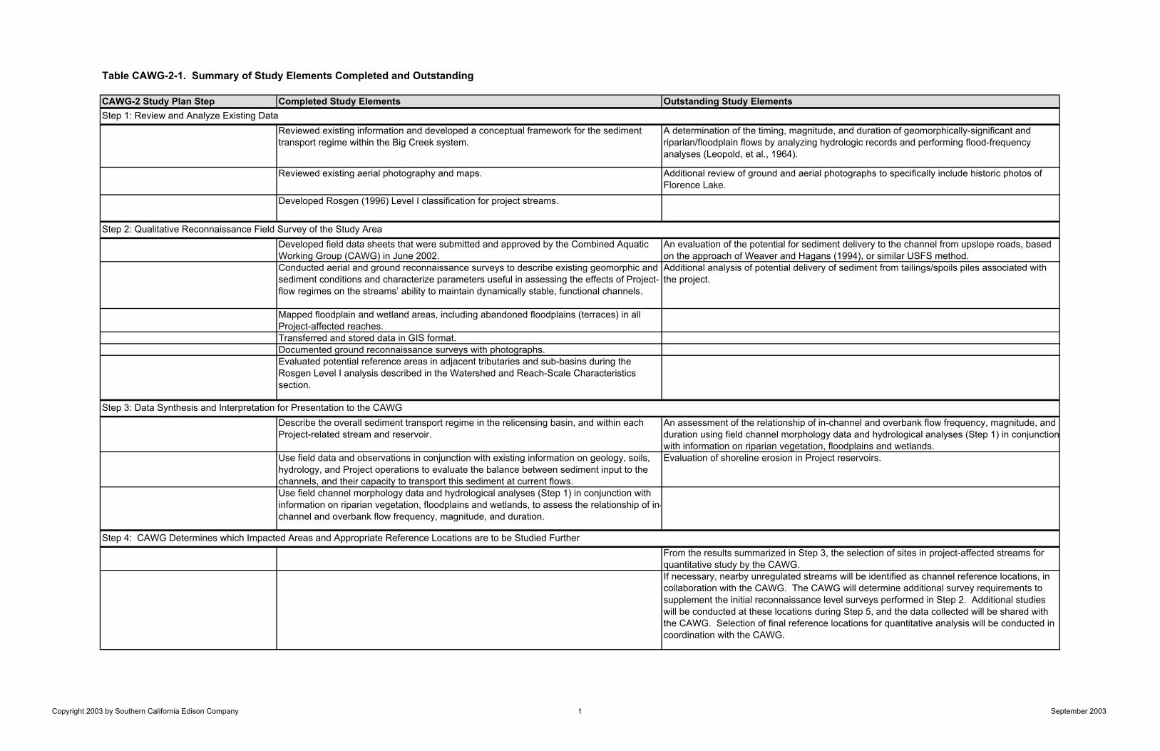
Table CAWG-2-1. Summary of Study Elements Completed and Outstanding
CAWG-2 Study Plan Step Completed Study Elements Outstanding Study Elements
Reviewed existing information and developed a conceptual framework for the sediment transport regime within the Big Creek system.
A determination of the timing, magnitude, and duration of geomorphically-significant and riparian/floodplain flows by analyzing hydrologic records and performing flood-frequency analyses (Leopold, et al., 1964).
Reviewed existing aerial photography and maps. Additional review of ground and aerial photographs to specifically include historic photos of Florence Lake.
Developed Rosgen (1996) Level I classification for project streams.
Developed field data sheets that were submitted and approved by the Combined Aquatic Working Group (CAWG) in June 2002.
An evaluation of the potential for sediment delivery to the channel from upslope roads, based on the approach of Weaver and Hagans (1994), or similar USFS method.
Conducted aerial and ground reconnaissance surveys to describe existing geomorphic and sediment conditions and characterize parameters useful in assessing the effects of Project-flow regimes on the streams’ ability to maintain dynamically stable, functional channels.
Additional analysis of potential delivery of sediment from tailings/spoils piles associated with the project.
Mapped floodplain and wetland areas, including abandoned floodplains (terraces) in all Project-affected reaches. Transferred and stored data in GIS format. Documented ground reconnaissance surveys with photographs. Evaluated potential reference areas in adjacent tributaries and sub-basins during the Rosgen Level I analysis described in the Watershed and Reach-Scale Characteristics section.
Describe the overall sediment transport regime in the relicensing basin, and within each Project-related stream and reservoir.
An assessment of the relationship of in-channel and overbank flow frequency, magnitude, and duration using field channel morphology data and hydrological analyses (Step 1) in conjunctionwith information on riparian vegetation, floodplains and wetlands.
Use field data and observations in conjunction with existing information on geology, soils, hydrology, and Project operations to evaluate the balance between sediment input to the channels, and their capacity to transport this sediment at current flows.
Evaluation of shoreline erosion in Project reservoirs.
Use field channel morphology data and hydrological analyses (Step 1) in conjunction with information on riparian vegetation, floodplains and wetlands, to assess the relationship of in-channel and overbank flow frequency, magnitude, and duration.
From the results summarized in Step 3, the selection of sites in project-affected streams for quantitative study by the CAWG. If necessary, nearby unregulated streams will be identified as channel reference locations, in collaboration with the CAWG. The CAWG will determine additional survey requirements to supplement the initial reconnaissance level surveys performed in Step 2. Additional studies will be conducted at these locations during Step 5, and the data collected will be shared with the CAWG. Selection of final reference locations for quantitative analysis will be conducted in coordination with the CAWG.
Step 4: CAWG Determines which Impacted Areas and Appropriate Reference Locations are to be Studied Further
Step 1: Review and Analyze Existing Data
Step 2: Qualitative Reconnaissance Field Survey of the Study Area
Step 3: Data Synthesis and Interpretation for Presentation to the CAWG
Copyright 2003 by Southern California Edison Company 1 September 2003

Table CAWG-2-1. Summary of Study Elements Completed and Outstanding (continued)
The installation of study [SCE] transects. The CAWG will determine the location of temporary and monumented transects. Collection of data elements outlined in the USFS Stream Condition Inventory (SCI) protocol at sites selected by the CAWG not already conducted during initial field surveys (Step 2).Collection of data elements outlined in the Proper Functioning Condition (PFC) protocol at sites selected by the CAWG not already conducted during initial surveys (Step 2).Comparison of data in project-affected reaches to similar data collected in reference reaches to assess the magnitude of project impact.Using existing and, if necessary, additional measurements of sediment accumulation, including woody debris, in reservoirs, and ongoing monitoring of the effects of SCE’s sediment management practices to characterize: (1) watershed sedimentation rates; and (2) potential effects of Project operation and maintenance over time on downstream reaches.
Quantification of woody debris in sensitive stream reaches following SCI protocol.
The approach and methodologies used to complete the study will be described and presented to the CAWG.The geomorphology data obtained from the project reaches will be compared to reference conditions to identify any differences in the stream channel geomorphology. Differences identified between project reaches and reference conditions will be evaluated to determine their geomorphological significance and whether they are attributable to project operations. Of the areas surveyed in Step 5, determine which impacts are considered adverse and, of those, which can be attributed to Project operations. The hydrologic and field-based determination of geomorphically-significant flows, conducted in Steps 1, 2, and 5, will be used as part of this assessment of degree of impact by Project operations. The CAWG will determine whether additional quantitative analysis is needed to supplement the studies conducted in Step 5.
Step 5: Quantitative Study of Impacted Areas and Associated Reference Sites
Step 6: Data Synthesis of Step 5 and Recommendations to CAWG
Copyright 2003 by Southern California Edison Company 2 September 2003
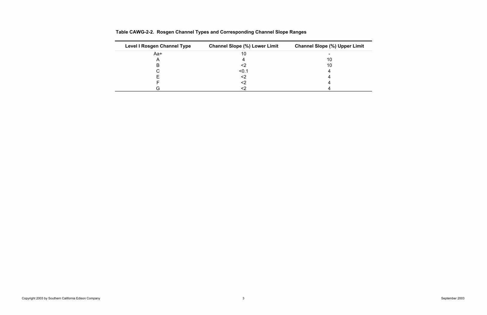
Table CAWG-2-2. Rosgen Channel Types and Corresponding Channel Slope Ranges
Level I Rosgen Channel Type Channel Slope (%) Lower Limit Channel Slope (%) Upper LimitAa+ 10 -
A 4 10B <2 10C <0.1 4E <2 4F <2 4G <2 4
Copyright 2003 by Southern California Edison Company 3 September 2003
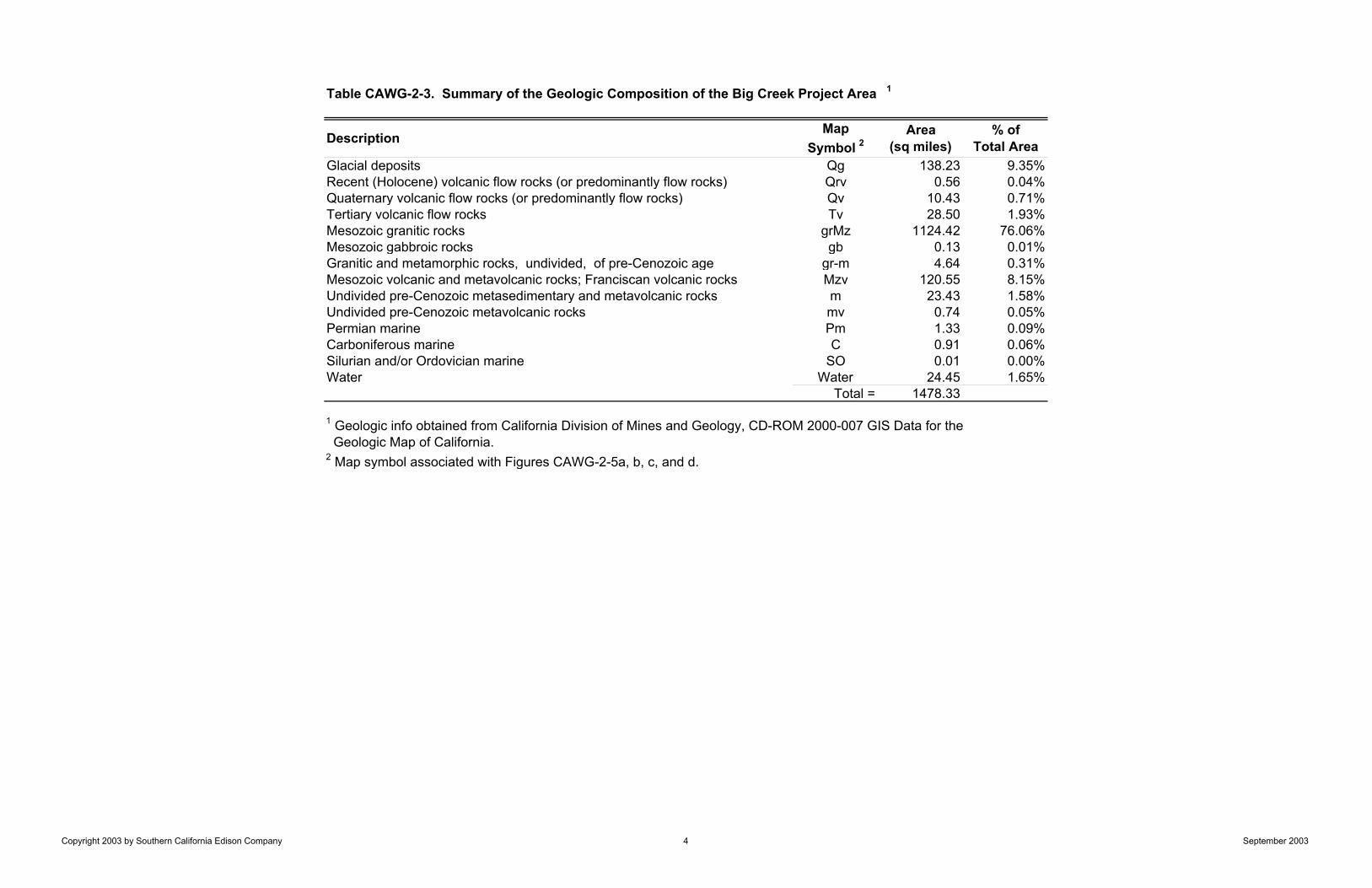
DescriptionMap
Symbol 2Area
(sq miles)% of
Total AreaGlacial deposits Qg 138.23 9.35%Recent (Holocene) volcanic flow rocks (or predominantly flow rocks) Qrv 0.56 0.04%Quaternary volcanic flow rocks (or predominantly flow rocks) Qv 10.43 0.71%Tertiary volcanic flow rocks Tv 28.50 1.93%Mesozoic granitic rocks grMz 1124.42 76.06%Mesozoic gabbroic rocks gb 0.13 0.01%Granitic and metamorphic rocks, undivided, of pre-Cenozoic age gr-m 4.64 0.31%Mesozoic volcanic and metavolcanic rocks; Franciscan volcanic rocks Mzv 120.55 8.15%Undivided pre-Cenozoic metasedimentary and metavolcanic rocks m 23.43 1.58%Undivided pre-Cenozoic metavolcanic rocks mv 0.74 0.05%Permian marine Pm 1.33 0.09%Carboniferous marine C 0.91 0.06%Silurian and/or Ordovician marine SO 0.01 0.00%Water Water 24.45 1.65%
Total = 1478.33
2 Map symbol associated with Figures CAWG-2-5a, b, c, and d.
1 Geologic info obtained from California Division of Mines and Geology, CD-ROM 2000-007 GIS Data for the Geologic Map of California.
Table CAWG-2-3. Summary of the Geologic Composition of the Big Creek Project Area 1
Copyright 2003 by Southern California Edison Company 4 September 2003
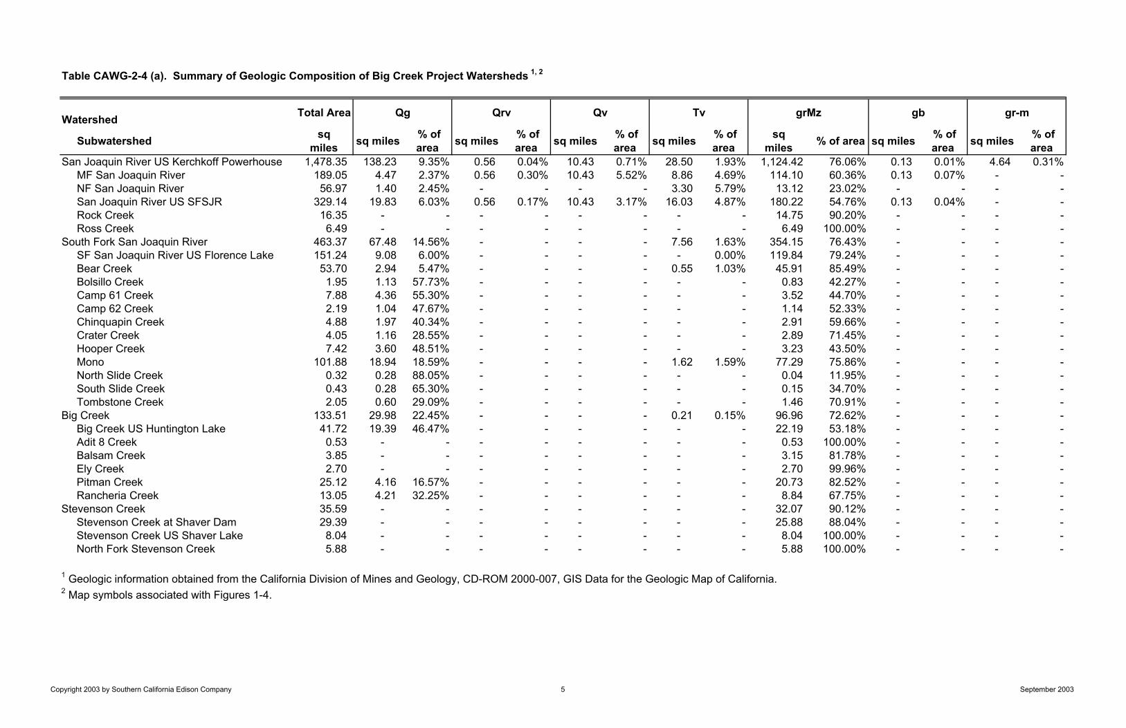
Table CAWG-2-4 (a). Summary of Geologic Composition of Big Creek Project Watersheds 1, 2
Watershed Total Area
Subwatershed sqmiles sq miles % of
area sq miles % of area sq miles % of
area sq miles % of area
sqmiles % of area sq miles % of
area sq miles % of area
San Joaquin River US Kerchkoff Powerhouse 1,478.35 138.23 9.35% 0.56 0.04% 10.43 0.71% 28.50 1.93% 1,124.42 76.06% 0.13 0.01% 4.64 0.31%MF San Joaquin River 189.05 4.47 2.37% 0.56 0.30% 10.43 5.52% 8.86 4.69% 114.10 60.36% 0.13 0.07% - -NF San Joaquin River 56.97 1.40 2.45% - - - - 3.30 5.79% 13.12 23.02% - - - -San Joaquin River US SFSJR 329.14 19.83 6.03% 0.56 0.17% 10.43 3.17% 16.03 4.87% 180.22 54.76% 0.13 0.04% - -Rock Creek 16.35 - - - - - - - - 14.75 90.20% - - - -Ross Creek 6.49 - - - - - - - - 6.49 100.00% - - - -
South Fork San Joaquin River 463.37 67.48 14.56% - - - - 7.56 1.63% 354.15 76.43% - - - -SF San Joaquin River US Florence Lake 151.24 9.08 6.00% - - - - - 0.00% 119.84 79.24% - - - -Bear Creek 53.70 2.94 5.47% - - - - 0.55 1.03% 45.91 85.49% - - - -Bolsillo Creek 1.95 1.13 57.73% - - - - - - 0.83 42.27% - - - -Camp 61 Creek 7.88 4.36 55.30% - - - - - - 3.52 44.70% - - - -Camp 62 Creek 2.19 1.04 47.67% - - - - - - 1.14 52.33% - - - -Chinquapin Creek 4.88 1.97 40.34% - - - - - - 2.91 59.66% - - - -Crater Creek 4.05 1.16 28.55% - - - - - - 2.89 71.45% - - - -Hooper Creek 7.42 3.60 48.51% - - - - - - 3.23 43.50% - - - -Mono 101.88 18.94 18.59% - - - - 1.62 1.59% 77.29 75.86% - - - -North Slide Creek 0.32 0.28 88.05% - - - - - - 0.04 11.95% - - - -South Slide Creek 0.43 0.28 65.30% - - - - - - 0.15 34.70% - - - -Tombstone Creek 2.05 0.60 29.09% - - - - - - 1.46 70.91% - - - -
Big Creek 133.51 29.98 22.45% - - - - 0.21 0.15% 96.96 72.62% - - - -Big Creek US Huntington Lake 41.72 19.39 46.47% - - - - - - 22.19 53.18% - - - -Adit 8 Creek 0.53 - - - - - - - - 0.53 100.00% - - - -Balsam Creek 3.85 - - - - - - - - 3.15 81.78% - - - -Ely Creek 2.70 - - - - - - - - 2.70 99.96% - - - -Pitman Creek 25.12 4.16 16.57% - - - - - - 20.73 82.52% - - - -Rancheria Creek 13.05 4.21 32.25% - - - - - - 8.84 67.75% - - - -
Stevenson Creek 35.59 - - - - - - - - 32.07 90.12% - - - -Stevenson Creek at Shaver Dam 29.39 - - - - - - - - 25.88 88.04% - - - -Stevenson Creek US Shaver Lake 8.04 - - - - - - - - 8.04 100.00% - - - -North Fork Stevenson Creek 5.88 - - - - - - - - 5.88 100.00% - - - -
1 Geologic information obtained from the California Division of Mines and Geology, CD-ROM 2000-007, GIS Data for the Geologic Map of California.2 Map symbols associated with Figures 1-4.
grMz gb gr-mQg Qrv Qv Tv
Copyright 2003 by Southern California Edison Company 5 September 2003
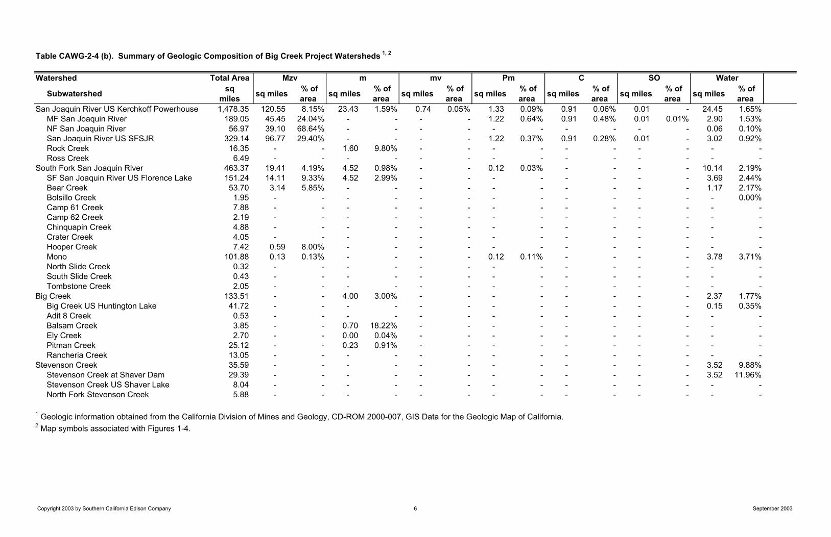
Table CAWG-2-4 (b). Summary of Geologic Composition of Big Creek Project Watersheds 1, 2
Watershed Total Area
Subwatershed sqmiles sq miles % of
area sq miles % of area sq miles % of
area sq miles % of area sq miles % of
area sq miles % of area sq miles % of
area San Joaquin River US Kerchkoff Powerhouse 1,478.35 120.55 8.15% 23.43 1.59% 0.74 0.05% 1.33 0.09% 0.91 0.06% 0.01 - 24.45 1.65%
MF San Joaquin River 189.05 45.45 24.04% - - - - 1.22 0.64% 0.91 0.48% 0.01 0.01% 2.90 1.53%NF San Joaquin River 56.97 39.10 68.64% - - - - - - - - - - 0.06 0.10%San Joaquin River US SFSJR 329.14 96.77 29.40% - - - - 1.22 0.37% 0.91 0.28% 0.01 - 3.02 0.92%Rock Creek 16.35 - - 1.60 9.80% - - - - - - - - - -Ross Creek 6.49 - - - - - - - - - - - - - -
South Fork San Joaquin River 463.37 19.41 4.19% 4.52 0.98% - - 0.12 0.03% - - - - 10.14 2.19%SF San Joaquin River US Florence Lake 151.24 14.11 9.33% 4.52 2.99% - - - - - - - - 3.69 2.44%Bear Creek 53.70 3.14 5.85% - - - - - - - - - - 1.17 2.17%Bolsillo Creek 1.95 - - - - - - - - - - - - - 0.00%Camp 61 Creek 7.88 - - - - - - - - - - - - - -Camp 62 Creek 2.19 - - - - - - - - - - - - - -Chinquapin Creek 4.88 - - - - - - - - - - - - - -Crater Creek 4.05 - - - - - - - - - - - - - -Hooper Creek 7.42 0.59 8.00% - - - - - - - - - - - -Mono 101.88 0.13 0.13% - - - - 0.12 0.11% - - - - 3.78 3.71%North Slide Creek 0.32 - - - - - - - - - - - - - -South Slide Creek 0.43 - - - - - - - - - - - - - -Tombstone Creek 2.05 - - - - - - - - - - - - - -
Big Creek 133.51 - - 4.00 3.00% - - - - - - - - 2.37 1.77%Big Creek US Huntington Lake 41.72 - - - - - - - - - - - - 0.15 0.35%Adit 8 Creek 0.53 - - - - - - - - - - - - - -Balsam Creek 3.85 - - 0.70 18.22% - - - - - - - - - -Ely Creek 2.70 - - 0.00 0.04% - - - - - - - - - -Pitman Creek 25.12 - - 0.23 0.91% - - - - - - - - - -Rancheria Creek 13.05 - - - - - - - - - - - - - -
Stevenson Creek 35.59 - - - - - - - - - - - - 3.52 9.88%Stevenson Creek at Shaver Dam 29.39 - - - - - - - - - - - - 3.52 11.96%Stevenson Creek US Shaver Lake 8.04 - - - - - - - - - - - - - -North Fork Stevenson Creek 5.88 - - - - - - - - - - - - - -
1 Geologic information obtained from the California Division of Mines and Geology, CD-ROM 2000-007, GIS Data for the Geologic Map of California.2 Map symbols associated with Figures 1-4.
Mzv SO Waterm mv Pm C
Copyright 2003 by Southern California Edison Company 6 September 2003

Table CAWG-2-5. Summary of Rosgen Stream Type Classification (Rosgen 1996)
Rosgen Channel
Type
Entrenchment Ratio
Width to Depth Ratio
SinuositySlope Range
(%)Morphological Characteristics
Aa+ <1.4 <12 1.0 – 1.1 >10Step-pool or cascading; plunge and scour pools, high gradient and high energy, low sediment storage, entrenched, low width-depth ratio, low sinuosity, stable
A <1.4 <12 1.0 – 1.2 4 - 10Step-pool or cascading; plunge and scour pools, high gradient and high energy, low sediment storage, entrenched, low width-depth ratio, low sinuosity, stable
B 1.4 – 2.2 >12 >1.2 <2 - 10Riffles and rapids; some scour pools, bars occur but infrequent, moderate gradient, moderately entrenched, moderate width-depth ratio and sinuosity, stable
C >2.2 >12 >1.4 <0.1 - 4Pool-riffle; meandering, point bars, floodplain, high width-depth ratio, slightly entrenched, high sinuosity, low to moderate gradient, banks can be stable or unstable
D >40 <0.1 - <4Braided; multiple channels, shifting bars, deposition, high sediment supply, bank erosion, no entrenchment, high width-depth ratio, low sinuosity, and low gradient
DA >2.2 Highly Variable
Highly Variable <0.5
Anastomsing; multiple stable channels, pool-riffle, vegetated floodplain and bars, stable banks, high width-depth ratio, no entrenchment, low sinuosity, and low gradient
E >2.2 <12 <2 - 4Meadow meanders; well-developed floodplain, pool-riffle, high sediment transport, low width-depth ratio, slightly entrenched, low to moderate gradient, high sinuosity
F <1.4 >12 <2 - 4
Valley/Canyon meanders; incised into valleys, small or no floodplain, pool-riffle, banks can be either stable or unstable, highly entrenched, moderate to high width-depth ratio, moderate to high sinuosity, moderate slope
G <1.4 <12 <2 - 4Gully; incised into hillslopes, alluvial fans, and meadows, high sediment supply, unstable banks, step-pool, entrenched, low width-depth ratio, moderate sinuosity, moderate gradient
Copyright 2003 by Southern California Edison Company 7 September 2003
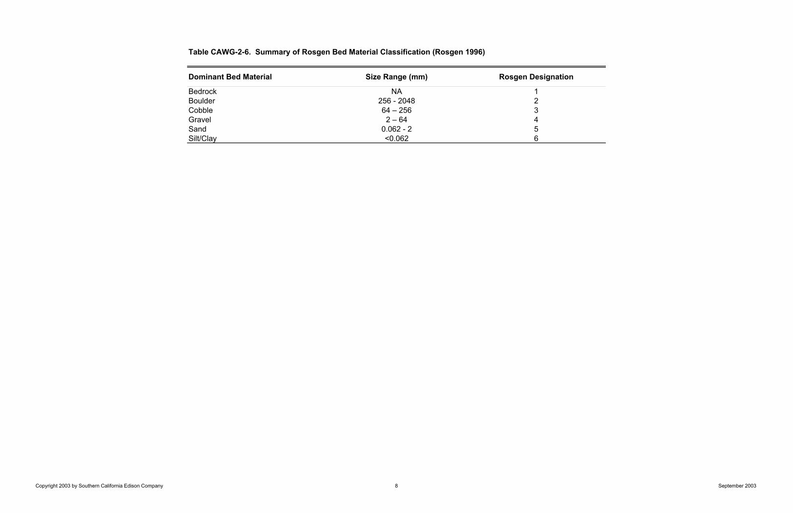
Table CAWG-2-6. Summary of Rosgen Bed Material Classification (Rosgen 1996)
Dominant Bed Material Size Range (mm) Rosgen Designation
Bedrock NA 1Boulder 256 - 2048 2Cobble 64 – 256 3Gravel 2 – 64 4Sand 0.062 - 2 5Silt/Clay <0.062 6
Copyright 2003 by Southern California Edison Company 8 September 2003
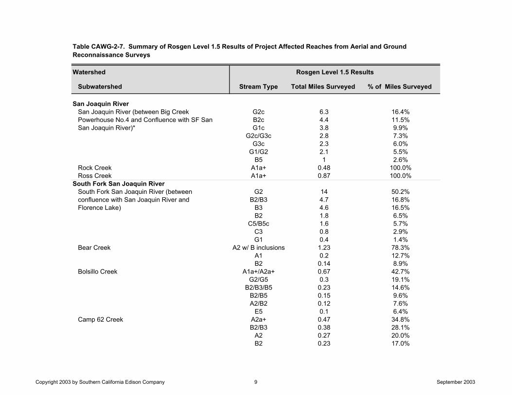
Watershed
Subwatershed Stream Type Total Miles Surveyed % of Miles Surveyed
San Joaquin RiverSan Joaquin River (between Big Creek G2c 6.3 16.4%Powerhouse No.4 and Confluence with SF San B2c 4.4 11.5%San Joaquin River)* G1c 3.8 9.9%
G2c/G3c 2.8 7.3%G3c 2.3 6.0%
G1/G2 2.1 5.5%B5 1 2.6%
Rock Creek A1a+ 0.48 100.0%Ross Creek A1a+ 0.87 100.0%
South Fork San Joaquin RiverSouth Fork San Joaquin River (between G2 14 50.2%confluence with San Joaquin River and B2/B3 4.7 16.8%Florence Lake) B3 4.6 16.5%
B2 1.8 6.5%C5/B5c 1.6 5.7%
C3 0.8 2.9%G1 0.4 1.4%
Bear Creek A2 w/ B inclusions 1.23 78.3%A1 0.2 12.7%B2 0.14 8.9%
Bolsillo Creek A1a+/A2a+ 0.67 42.7%G2/G5 0.3 19.1%
B2/B3/B5 0.23 14.6%B2/B5 0.15 9.6%A2/B2 0.12 7.6%
E5 0.1 6.4%Camp 62 Creek A2a+ 0.47 34.8%
B2/B3 0.38 28.1%A2 0.27 20.0%B2 0.23 17.0%
Rosgen Level 1.5 Results
Table CAWG-2-7. Summary of Rosgen Level 1.5 Results of Project Affected Reaches from Aerial and Ground Reconnaissance Surveys
Copyright 2003 by Southern California Edison Company 9 September 2003
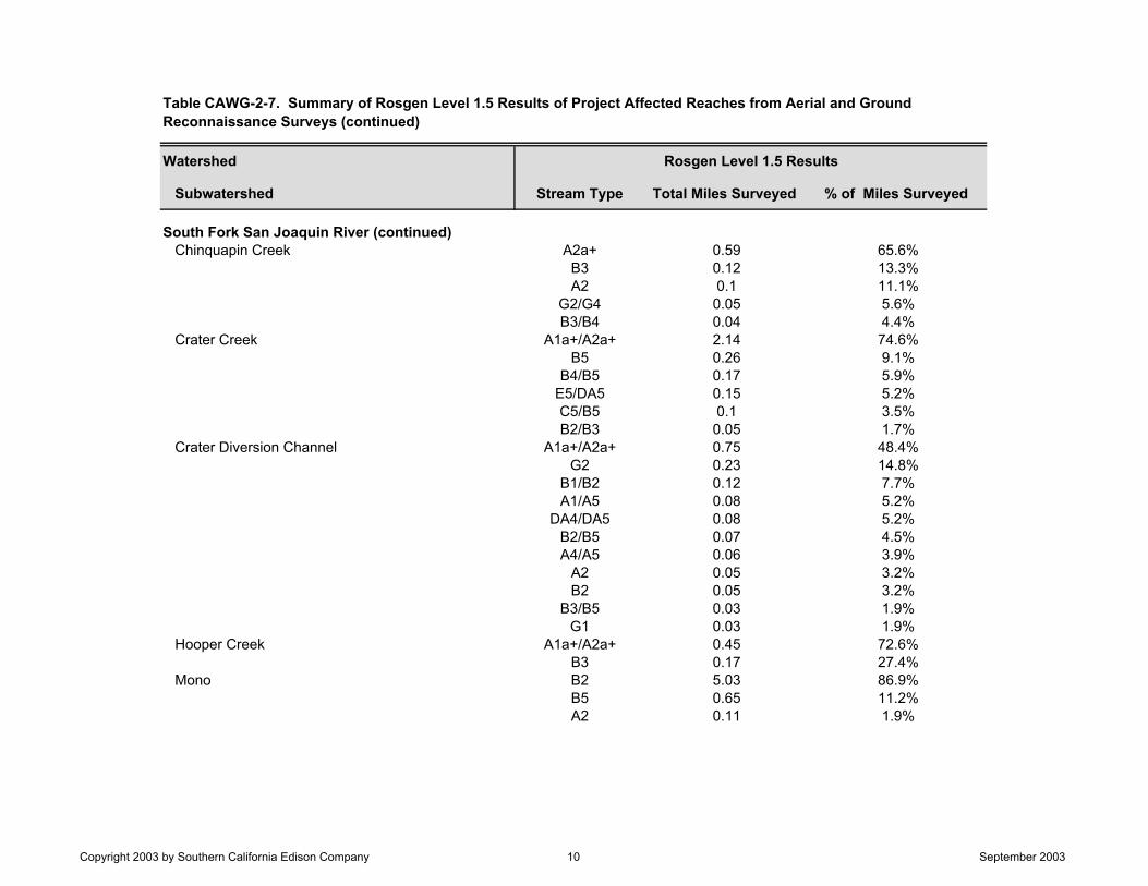
Watershed
Subwatershed Stream Type Total Miles Surveyed % of Miles Surveyed
South Fork San Joaquin River (continued)Chinquapin Creek A2a+ 0.59 65.6%
B3 0.12 13.3%A2 0.1 11.1%
G2/G4 0.05 5.6%B3/B4 0.04 4.4%
Crater Creek A1a+/A2a+ 2.14 74.6%B5 0.26 9.1%
B4/B5 0.17 5.9%E5/DA5 0.15 5.2%C5/B5 0.1 3.5%B2/B3 0.05 1.7%
Crater Diversion Channel A1a+/A2a+ 0.75 48.4%G2 0.23 14.8%
B1/B2 0.12 7.7%A1/A5 0.08 5.2%
DA4/DA5 0.08 5.2%B2/B5 0.07 4.5%A4/A5 0.06 3.9%
A2 0.05 3.2%B2 0.05 3.2%
B3/B5 0.03 1.9%G1 0.03 1.9%
Hooper Creek A1a+/A2a+ 0.45 72.6%B3 0.17 27.4%
Mono B2 5.03 86.9%B5 0.65 11.2%A2 0.11 1.9%
Table CAWG-2-7. Summary of Rosgen Level 1.5 Results of Project Affected Reaches from Aerial and Ground Reconnaissance Surveys (continued)
Rosgen Level 1.5 Results
Copyright 2003 by Southern California Edison Company 10 September 2003
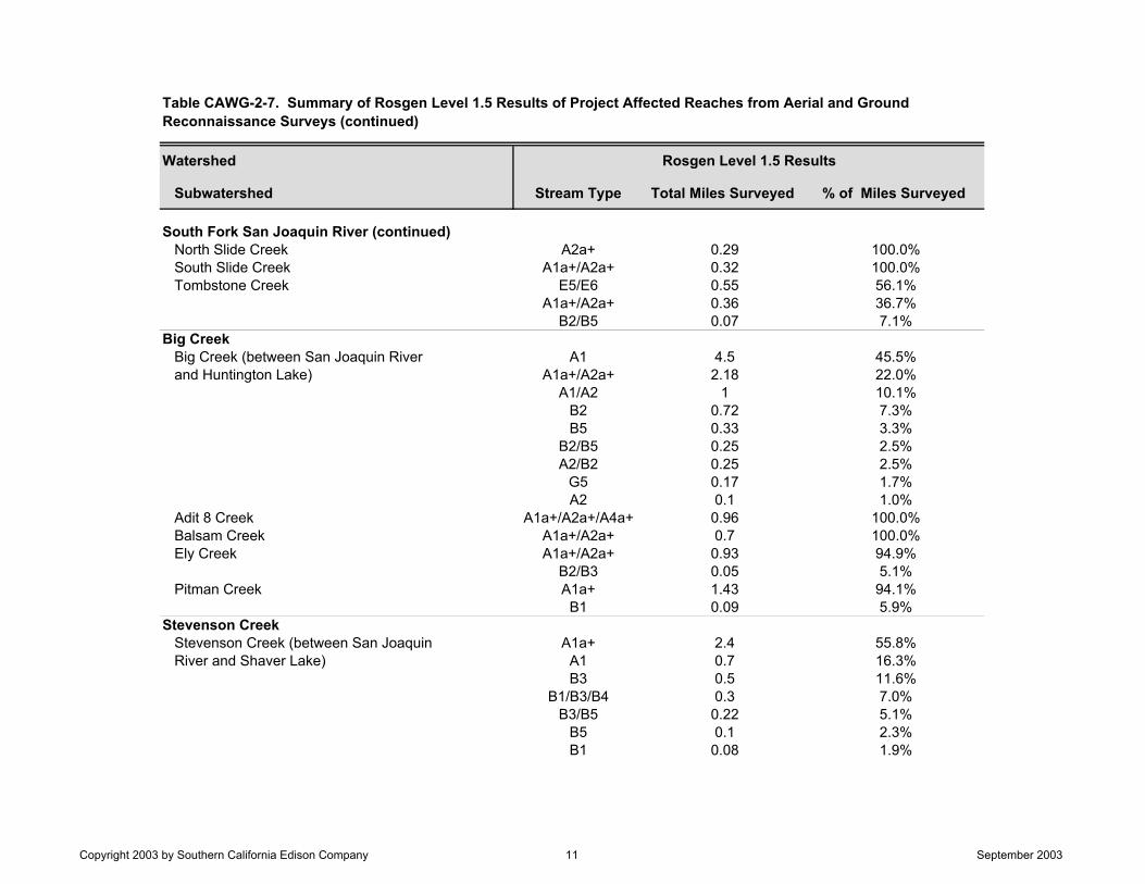
Watershed
Subwatershed Stream Type Total Miles Surveyed % of Miles Surveyed
South Fork San Joaquin River (continued)North Slide Creek A2a+ 0.29 100.0%South Slide Creek A1a+/A2a+ 0.32 100.0%Tombstone Creek E5/E6 0.55 56.1%
A1a+/A2a+ 0.36 36.7%B2/B5 0.07 7.1%
Big CreekBig Creek (between San Joaquin River A1 4.5 45.5%and Huntington Lake) A1a+/A2a+ 2.18 22.0%
A1/A2 1 10.1%B2 0.72 7.3%B5 0.33 3.3%
B2/B5 0.25 2.5%A2/B2 0.25 2.5%
G5 0.17 1.7%A2 0.1 1.0%
Adit 8 Creek A1a+/A2a+/A4a+ 0.96 100.0%Balsam Creek A1a+/A2a+ 0.7 100.0%Ely Creek A1a+/A2a+ 0.93 94.9%
B2/B3 0.05 5.1%Pitman Creek A1a+ 1.43 94.1%
B1 0.09 5.9%Stevenson Creek
Stevenson Creek (between San Joaquin A1a+ 2.4 55.8%River and Shaver Lake) A1 0.7 16.3%
B3 0.5 11.6%B1/B3/B4 0.3 7.0%
B3/B5 0.22 5.1%B5 0.1 2.3%B1 0.08 1.9%
Table CAWG-2-7. Summary of Rosgen Level 1.5 Results of Project Affected Reaches from Aerial and Ground Reconnaissance Surveys (continued)
Rosgen Level 1.5 Results
Copyright 2003 by Southern California Edison Company 11 September 2003

Watershed
Subwatershed Stream Type Total Miles Surveyed % of Miles Surveyed
Stevenson Creek (continued)North Fork Stevenson Creek A1a+/A2a+ 1.41 53.2%
C3 0.3 11.3%G1 0.3 11.3%B3 0.3 11.3%
B1/B2 0.14 5.3%C4 0.1 3.8%A1 0.1 3.8%
Total: 90.4
Redinger Lake, Dam 6 Lake, and Mammoth Pool account for approximately 15.7 miles or 17% of total stream miles.
Table CAWG-2-7. Summary of Rosgen Level 1.5 Results of Project Affected Reaches from Aerial and Ground Reconnaissance Surveys (continued)
Rosgen Level 1.5 Results
Copyright 2003 by Southern California Edison Company 12 September 2003
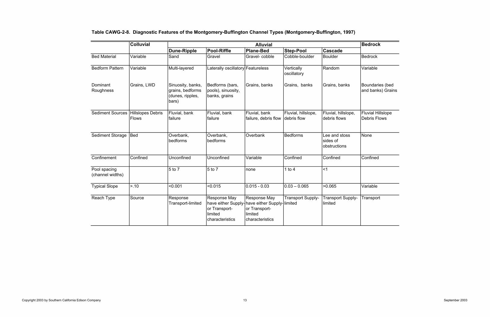
Table CAWG-2-8. Diagnostic Features of the Montgomery-Buffington Channel Types (Montgomery-Buffington, 1997)
Colluvial BedrockDune-Ripple Pool-Riffle Plane-Bed Step-Pool Cascade
Bed Material Variable Sand Gravel Gravel- cobble Cobble-boulder Boulder Bedrock
Bedform Pattern Variable Multi-layered Laterally oscillatory Featureless Vertically oscillatory
Random Variable
Dominant Roughness
Grains, LWD Sinuosity, banks, grains, bedforms (dunes, ripples, bars)
Bedforms (bars, pools), sinuosity, banks, grains
Grains, banks Grains, banks Grains, banks Boundaries (bed and banks) Grains
Sediment Sources Hillslopes Debris Flows
Fluvial, bank failure
Fluvial, bank failure
Fluvial, bank failure, debris flow
Fluvial, hillslope, debris flow
Fluvial, hillslope, debris flows
Fluvial Hillslope Debris Flows
Sediment Storage Bed Overbank, bedforms
Overbank, bedforms
Overbank Bedforms Lee and stoss sides of obstructions
None
Confinement Confined Unconfined Unconfined Variable Confined Confined Confined
Pool spacing (channel widths)
5 to 7 5 to 7 none 1 to 4 <1
Typical Slope >.10 <0.001 <0.015 0.015 - 0.03 0.03 – 0.065 >0.065 Variable
Reach Type Source Response Transport-limited
Response May have either Supply-or Transport-limited characteristics
Response May have either Supply-or Transport-limited characteristics
Transport Supply-limited
Transport Supply-limited
Transport
Alluvial
Copyright 2003 by Southern California Edison Company 13 September 2003
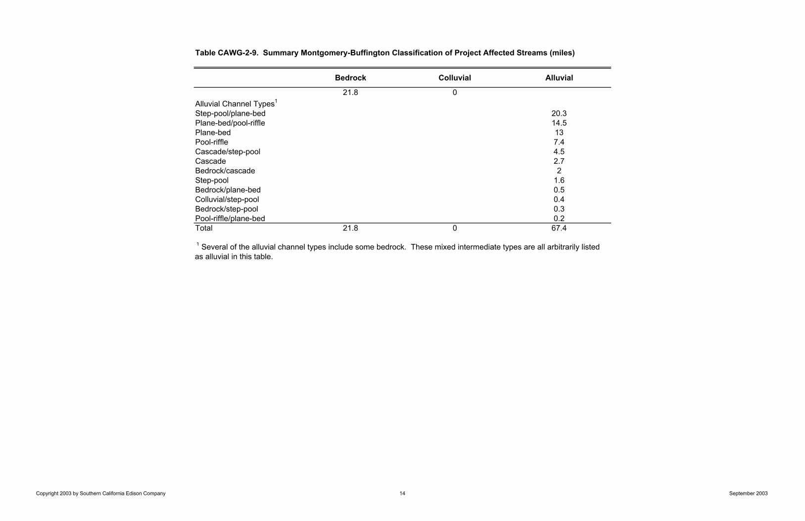
Table CAWG-2-9. Summary Montgomery-Buffington Classification of Project Affected Streams (miles)
Bedrock Colluvial Alluvial
21.8 0Alluvial Channel Types1
Step-pool/plane-bed 20.3Plane-bed/pool-riffle 14.5Plane-bed 13Pool-riffle 7.4Cascade/step-pool 4.5Cascade 2.7Bedrock/cascade 2Step-pool 1.6Bedrock/plane-bed 0.5Colluvial/step-pool 0.4Bedrock/step-pool 0.3Pool-riffle/plane-bed 0.2Total 21.8 0 67.4
1 Several of the alluvial channel types include some bedrock. These mixed intermediate types are all arbitrarily listed as alluvial in this table.
Copyright 2003 by Southern California Edison Company 14 September 2003

Table CAWG-2-10. Channel Response Potential to Moderate Changes in Sediment Supply and Discharge1
Morphology Width Depth Slope Particle Size
Sediment Storage Roughness
ResponseDune-ripple2 + + + - + +
Pool-riffle + + + + + +Plane-bed P + + + P P
TransportStep-pool - P P P P PCascade - - - P - PBedrock - - - - - -
SourceColluvial2 P P - P + -
+ = likely to change P = possible to change - = unlikely to change
1 adapted from Montgomery and Buffington (1997)2 not found along project affected streams
Copyright 2003 by Southern California Edison Company 15 September 2003

Table CAWG-2-11. Channel Responsiveness Based on Rosgen Classification
Watershed Subwatershed Total LengthDownstream RM Upstream RM (miles) Responsive Not Responsive
San Joaquin River (between Big Creek Powerhouse No.4 and Confluence with SF San Joaquin River)
0 3.3 3.3 G1c X
3.3 5.6 2.3 G3c X5.6 6.1 0.5 G1c X6.1 11.3 Redinger Lake --11.3 17 5.7 G2c X17 18.2 Dam 6 Lake --
18.2 22.6 4.4 B2c X22.6 25.4 2.8 G2c/G3c25.4 25.6 0.2 B5 X25.6 26.2 0.6 G2c X26.2 35.5 Mammoth Pool --35.5 37.6 2.1 G1/G2 X37.6 38.4 0.8 B5 X
Ross Creek 0 0.87 0.87 A1a+ X
Rock Creek 0 0.48 0.48 A1a+ X
South Fork San Joaquin River 0 0.7 0.7 G2 X0.7 1 0.3 B3 X1 1.55 0.55 G2 X
1.55 1.9 0.35 B3 X1.9 14 12.1 G2 X14 15.9 1.9 B3 X
15.9 19 3.1 B2/B3 X19 19.35 0.35 G2 X
19.35 19.8 0.45 B3 X19.8 19.9 0.1 G2 X19.9 20.1 0.2 B3 X20.1 20.9 0.8 C3 X20.9 21.1 0.2 G1 X21.1 21.8 0.7 B2/B3 X21.8 22 0.2 G2 X22 23.4 1.4 B3 X
23.4 25.2 1.8 B2 X
ResponsivenessRosgen Reach TypeStation to Station (River Mile (RM))
South Fork San Joaquin River
San Joaquin River
Copyright 2003 by Southern California Edison Company 16 September 2003
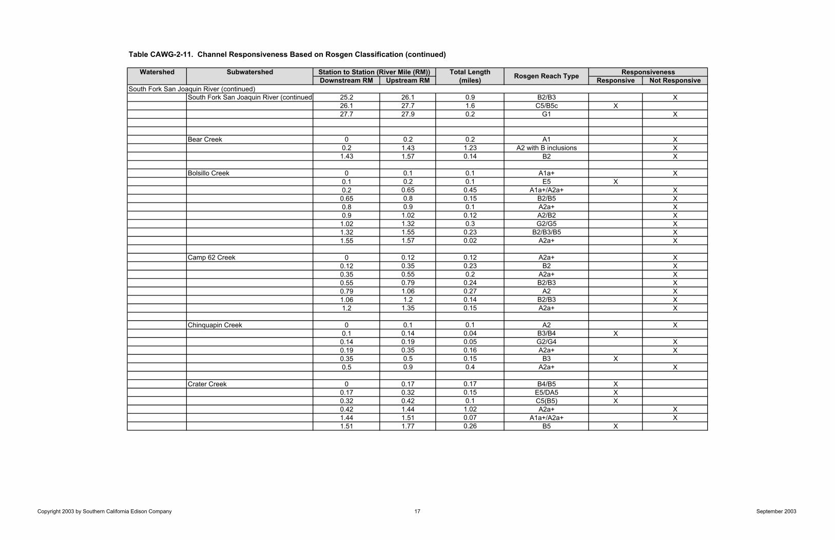
Table CAWG-2-11. Channel Responsiveness Based on Rosgen Classification (continued)
Watershed Subwatershed Total LengthDownstream RM Upstream RM (miles) Responsive Not Responsive
South Fork San Joaquin River (continued) 25.2 26.1 0.9 B2/B3 X26.1 27.7 1.6 C5/B5c X27.7 27.9 0.2 G1 X
Bear Creek 0 0.2 0.2 A1 X0.2 1.43 1.23 A2 with B inclusions X1.43 1.57 0.14 B2 X
Bolsillo Creek 0 0.1 0.1 A1a+ X0.1 0.2 0.1 E5 X0.2 0.65 0.45 A1a+/A2a+ X0.65 0.8 0.15 B2/B5 X0.8 0.9 0.1 A2a+ X0.9 1.02 0.12 A2/B2 X1.02 1.32 0.3 G2/G5 X1.32 1.55 0.23 B2/B3/B5 X1.55 1.57 0.02 A2a+ X
Camp 62 Creek 0 0.12 0.12 A2a+ X0.12 0.35 0.23 B2 X0.35 0.55 0.2 A2a+ X0.55 0.79 0.24 B2/B3 X0.79 1.06 0.27 A2 X1.06 1.2 0.14 B2/B3 X1.2 1.35 0.15 A2a+ X
Chinquapin Creek 0 0.1 0.1 A2 X0.1 0.14 0.04 B3/B4 X0.14 0.19 0.05 G2/G4 X0.19 0.35 0.16 A2a+ X0.35 0.5 0.15 B3 X0.5 0.9 0.4 A2a+ X
Crater Creek 0 0.17 0.17 B4/B5 X0.17 0.32 0.15 E5/DA5 X0.32 0.42 0.1 C5(B5) X0.42 1.44 1.02 A2a+ X1.44 1.51 0.07 A1a+/A2a+ X1.51 1.77 0.26 B5 X
South Fork San Joaquin River (continued)
Station to Station (River Mile (RM)) Rosgen Reach Type Responsiveness
Copyright 2003 by Southern California Edison Company 17 September 2003

Table CAWG-2-11. Channel Responsiveness Based on Rosgen Classification (continued)
Watershed Subwatershed Total LengthDownstream RM Upstream RM (miles) Responsive Not Responsive
Crater Creek (continued) 1.77 1.82 0.05 B2/B3 X1.82 2.1 0.28 A1a+/A2a+ X2.1 2.87 0.77 A2a+ with A2/B2 inclusions X
Crater Diversion Channel 0.65 0.72 0.07 B2/B5 X0.72 0.8 0.08 G2 X0.8 0.85 0.05 B2 X0.85 0.88 0.03 A2a+ X0.88 0.98 0.1 G2 X0.98 1.1 0.12 A1a+/A2a+ X1.1 1.13 0.03 G1 X1.13 1.24 0.11 A1a+ X1.24 1.3 0.06 A4/A5 X1.3 1.6 0.3 A1a+ X1.6 1.7 0.1 A1a+/A2a+ X1.7 1.78 0.08 A1/A5 X1.78 1.9 0.12 B1/B2 X1.9 1.98 0.08 DA4/DA5 X1.98 2.07 0.09 A2a+ X2.07 2.1 0.03 B3/B5 X2.1 2.15 0.05 G2 X2.15 2.2 0.05 A2 X
Hooper Creek 0 0.08 0.08 A2a+ X0.08 0.25 0.17 B3 X0.25 0.7 0.45 A1a+/A2a+ X
Mono Creek 0 2.4 2.4 B2 X(below diversion) 2.4 2.8 0.4 B5 X
2.8 3.5 0.7 B2 X3.5 3.75 0.25 B5 X3.75 5.68 1.93 B2 X5.68 5.79 0.11 A2 X
North Slide Creek #REF! 0.29 #REF! A2a+ X
South Slide Creek 0 0.27 0.27 A2a+ X0.27 0.32 0.05 A1a+ X
South Fork San Joaquin River (continued)
Station to Station (River Mile (RM)) Rosgen Reach Type Responsiveness
Copyright 2003 by Southern California Edison Company 18 September 2003
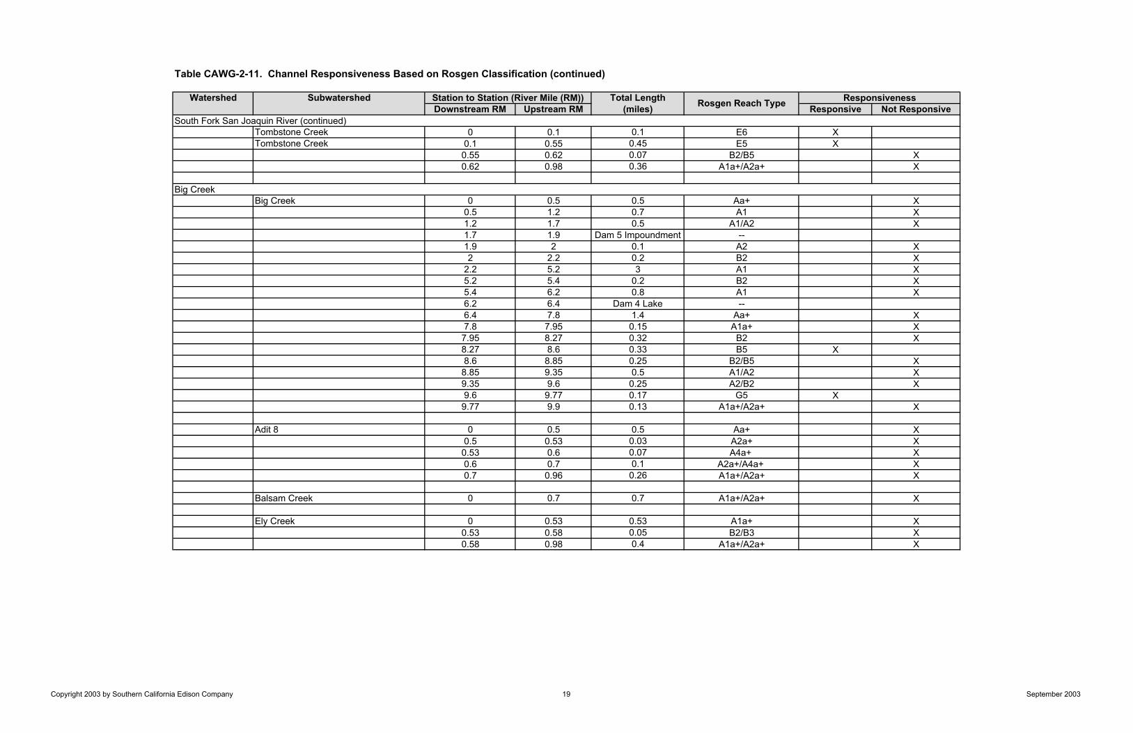
Table CAWG-2-11. Channel Responsiveness Based on Rosgen Classification (continued)
Watershed Subwatershed Total LengthDownstream RM Upstream RM (miles) Responsive Not Responsive
Tombstone Creek 0 0.1 0.1 E6 XTombstone Creek 0.1 0.55 0.45 E5 X
0.55 0.62 0.07 B2/B5 X0.62 0.98 0.36 A1a+/A2a+ X
Big Creek 0 0.5 0.5 Aa+ X0.5 1.2 0.7 A1 X1.2 1.7 0.5 A1/A2 X1.7 1.9 Dam 5 Impoundment --1.9 2 0.1 A2 X2 2.2 0.2 B2 X
2.2 5.2 3 A1 X5.2 5.4 0.2 B2 X5.4 6.2 0.8 A1 X6.2 6.4 Dam 4 Lake --6.4 7.8 1.4 Aa+ X7.8 7.95 0.15 A1a+ X7.95 8.27 0.32 B2 X8.27 8.6 0.33 B5 X8.6 8.85 0.25 B2/B5 X8.85 9.35 0.5 A1/A2 X9.35 9.6 0.25 A2/B2 X9.6 9.77 0.17 G5 X9.77 9.9 0.13 A1a+/A2a+ X
Adit 8 0 0.5 0.5 Aa+ X0.5 0.53 0.03 A2a+ X0.53 0.6 0.07 A4a+ X0.6 0.7 0.1 A2a+/A4a+ X0.7 0.96 0.26 A1a+/A2a+ X
Balsam Creek 0 0.7 0.7 A1a+/A2a+ X
Ely Creek 0 0.53 0.53 A1a+ X0.53 0.58 0.05 B2/B3 X0.58 0.98 0.4 A1a+/A2a+ X
South Fork San Joaquin River (continued)
Big Creek
Station to Station (River Mile (RM)) Rosgen Reach Type Responsiveness
Copyright 2003 by Southern California Edison Company 19 September 2003
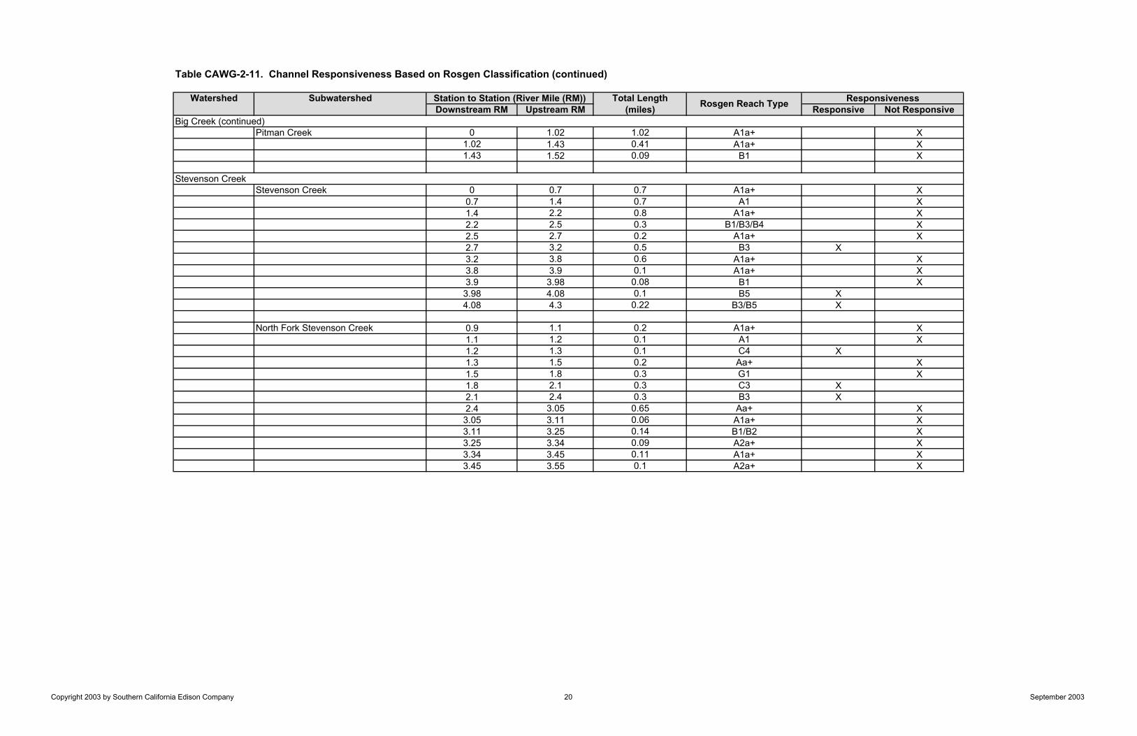
Table CAWG-2-11. Channel Responsiveness Based on Rosgen Classification (continued)
Watershed Subwatershed Total LengthDownstream RM Upstream RM (miles) Responsive Not Responsive
Pitman Creek 0 1.02 1.02 A1a+ X1.02 1.43 0.41 A1a+ X1.43 1.52 0.09 B1 X
Stevenson Creek 0 0.7 0.7 A1a+ X0.7 1.4 0.7 A1 X1.4 2.2 0.8 A1a+ X2.2 2.5 0.3 B1/B3/B4 X2.5 2.7 0.2 A1a+ X2.7 3.2 0.5 B3 X3.2 3.8 0.6 A1a+ X3.8 3.9 0.1 A1a+ X3.9 3.98 0.08 B1 X3.98 4.08 0.1 B5 X4.08 4.3 0.22 B3/B5 X
North Fork Stevenson Creek 0.9 1.1 0.2 A1a+ X1.1 1.2 0.1 A1 X1.2 1.3 0.1 C4 X1.3 1.5 0.2 Aa+ X1.5 1.8 0.3 G1 X1.8 2.1 0.3 C3 X2.1 2.4 0.3 B3 X2.4 3.05 0.65 Aa+ X3.05 3.11 0.06 A1a+ X3.11 3.25 0.14 B1/B2 X3.25 3.34 0.09 A2a+ X3.34 3.45 0.11 A1a+ X3.45 3.55 0.1 A2a+ X
Big Creek (continued)
Stevenson Creek
Station to Station (River Mile (RM)) Rosgen Reach Type Responsiveness
Copyright 2003 by Southern California Edison Company 20 September 2003
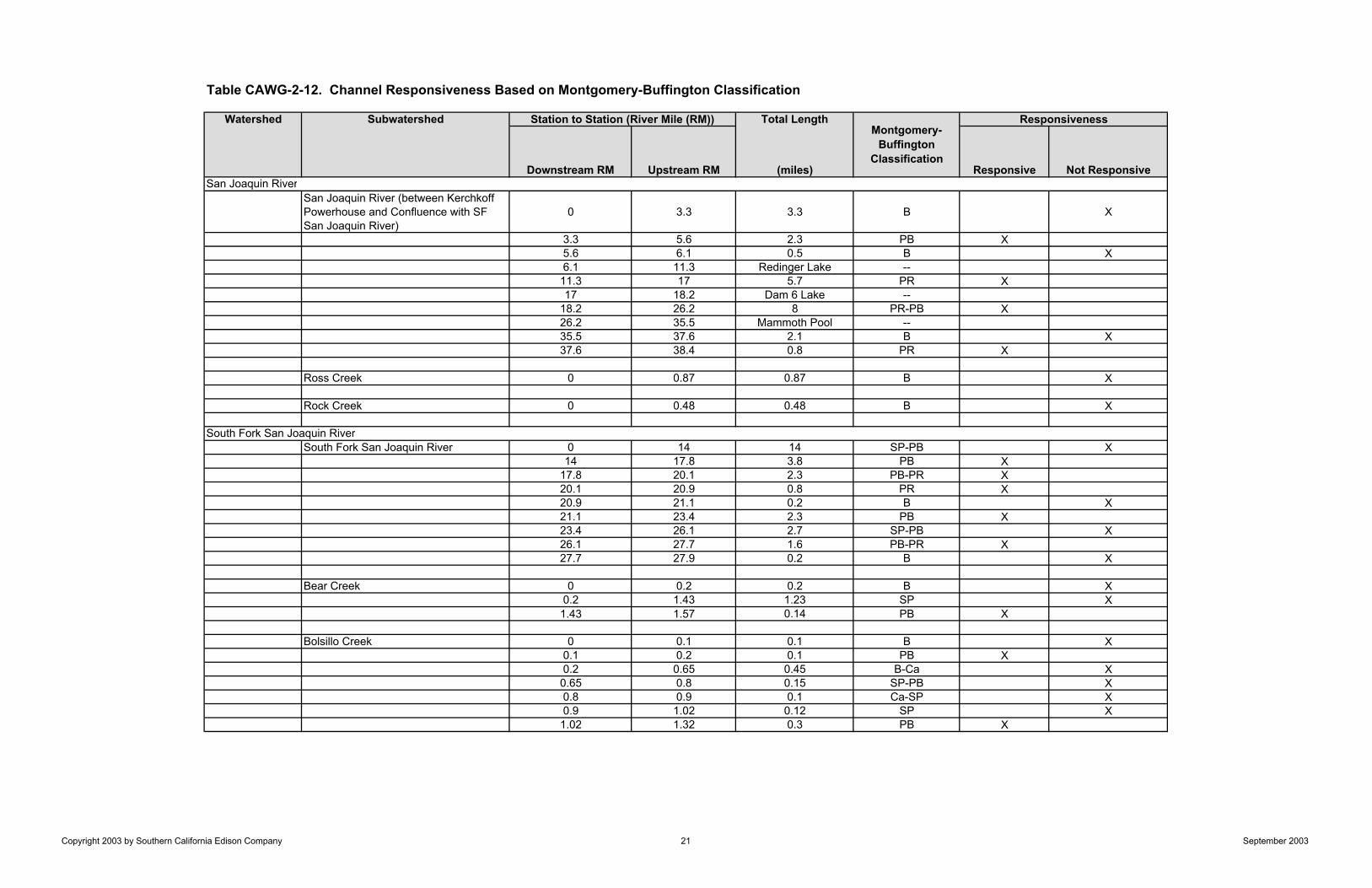
Table CAWG-2-12. Channel Responsiveness Based on Montgomery-Buffington Classification
Watershed Subwatershed Total Length
Downstream RM Upstream RM (miles) Responsive Not Responsive
San Joaquin River (between Kerchkoff Powerhouse and Confluence with SF San Joaquin River)
0 3.3 3.3 B X
3.3 5.6 2.3 PB X5.6 6.1 0.5 B X6.1 11.3 Redinger Lake --11.3 17 5.7 PR X17 18.2 Dam 6 Lake --
18.2 26.2 8 PR-PB X26.2 35.5 Mammoth Pool --35.5 37.6 2.1 B X37.6 38.4 0.8 PR X
Ross Creek 0 0.87 0.87 B X
Rock Creek 0 0.48 0.48 B X
South Fork San Joaquin River 0 14 14 SP-PB X14 17.8 3.8 PB X
17.8 20.1 2.3 PB-PR X20.1 20.9 0.8 PR X20.9 21.1 0.2 B X21.1 23.4 2.3 PB X23.4 26.1 2.7 SP-PB X26.1 27.7 1.6 PB-PR X27.7 27.9 0.2 B X
Bear Creek 0 0.2 0.2 B X0.2 1.43 1.23 SP X1.43 1.57 0.14 PB X
Bolsillo Creek 0 0.1 0.1 B X0.1 0.2 0.1 PB X0.2 0.65 0.45 B-Ca X0.65 0.8 0.15 SP-PB X0.8 0.9 0.1 Ca-SP X0.9 1.02 0.12 SP X1.02 1.32 0.3 PB X
Station to Station (River Mile (RM))
South Fork San Joaquin River
ResponsivenessMontgomery-
BuffingtonClassification
San Joaquin River
Copyright 2003 by Southern California Edison Company 21 September 2003
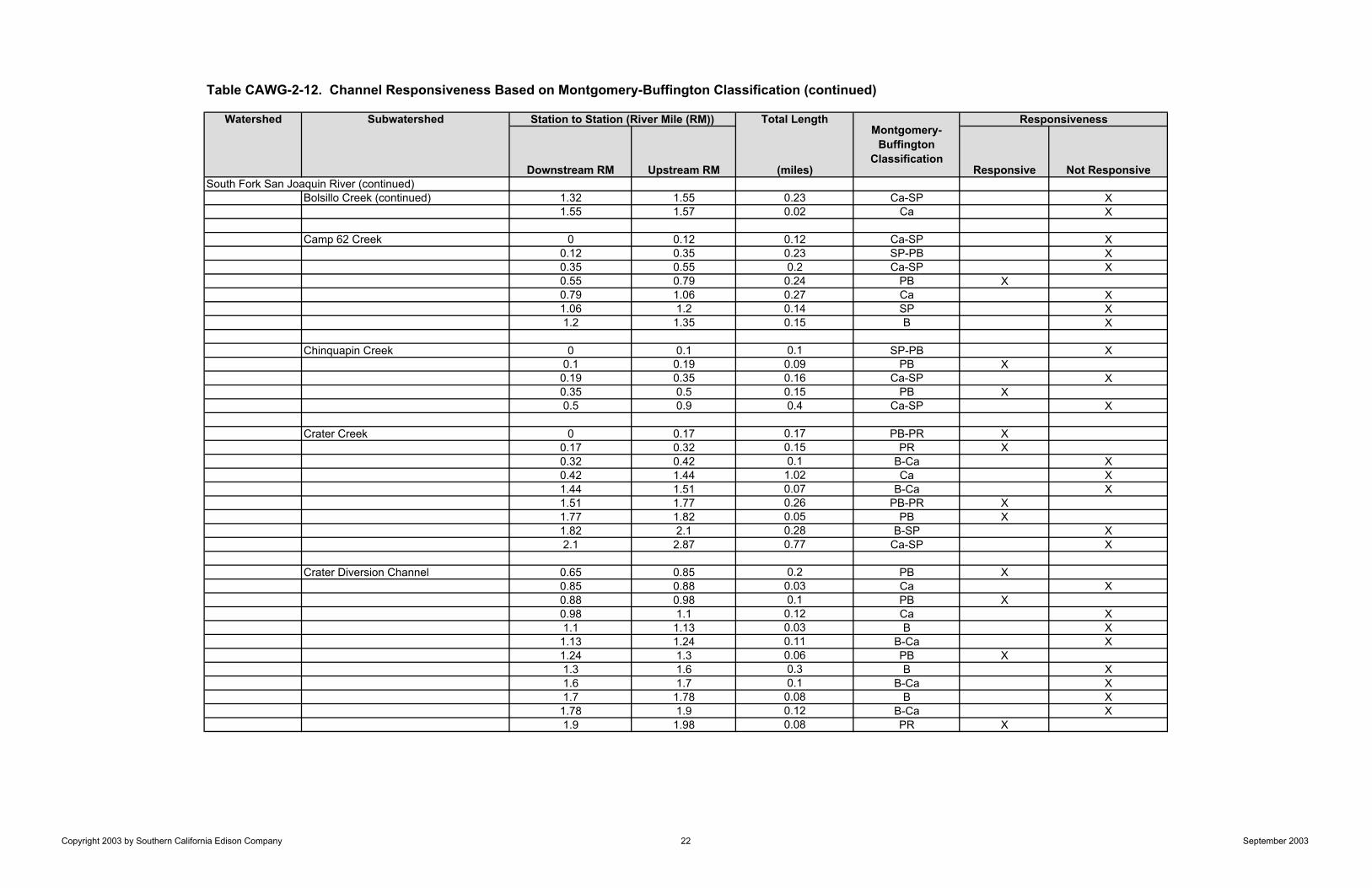
Table CAWG-2-12. Channel Responsiveness Based on Montgomery-Buffington Classification (continued)
Watershed Subwatershed Total Length
Downstream RM Upstream RM (miles) Responsive Not ResponsiveSouth Fork San Joaquin River (continued)
Bolsillo Creek (continued) 1.32 1.55 0.23 Ca-SP X1.55 1.57 0.02 Ca X
Camp 62 Creek 0 0.12 0.12 Ca-SP X0.12 0.35 0.23 SP-PB X0.35 0.55 0.2 Ca-SP X0.55 0.79 0.24 PB X0.79 1.06 0.27 Ca X1.06 1.2 0.14 SP X1.2 1.35 0.15 B X
Chinquapin Creek 0 0.1 0.1 SP-PB X0.1 0.19 0.09 PB X0.19 0.35 0.16 Ca-SP X0.35 0.5 0.15 PB X0.5 0.9 0.4 Ca-SP X
Crater Creek 0 0.17 0.17 PB-PR X0.17 0.32 0.15 PR X0.32 0.42 0.1 B-Ca X0.42 1.44 1.02 Ca X1.44 1.51 0.07 B-Ca X1.51 1.77 0.26 PB-PR X1.77 1.82 0.05 PB X1.82 2.1 0.28 B-SP X2.1 2.87 0.77 Ca-SP X
Crater Diversion Channel 0.65 0.85 0.2 PB X0.85 0.88 0.03 Ca X0.88 0.98 0.1 PB X0.98 1.1 0.12 Ca X1.1 1.13 0.03 B X1.13 1.24 0.11 B-Ca X1.24 1.3 0.06 PB X1.3 1.6 0.3 B X1.6 1.7 0.1 B-Ca X1.7 1.78 0.08 B X1.78 1.9 0.12 B-Ca X1.9 1.98 0.08 PR X
Station to Station (River Mile (RM))Montgomery-
BuffingtonClassification
Responsiveness
Copyright 2003 by Southern California Edison Company 22 September 2003
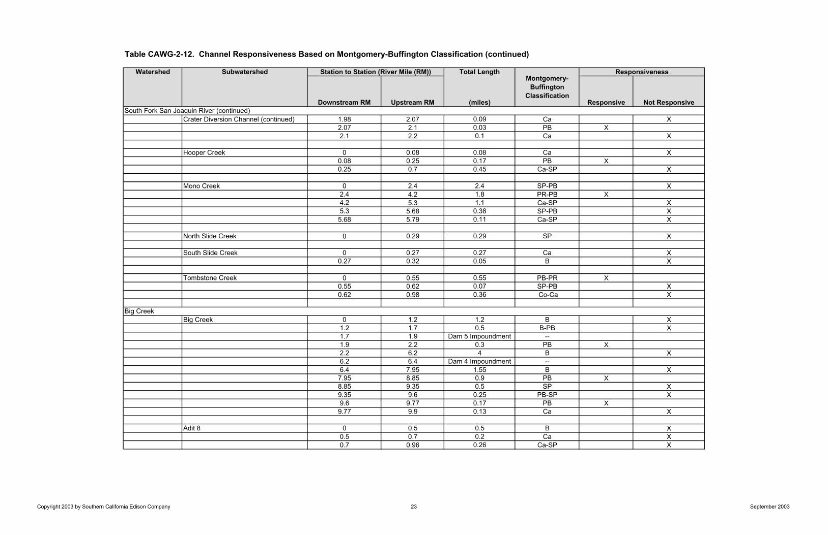
Table CAWG-2-12. Channel Responsiveness Based on Montgomery-Buffington Classification (continued)
Watershed Subwatershed Total Length
Downstream RM Upstream RM (miles) Responsive Not Responsive
Crater Diversion Channel (continued) 1.98 2.07 0.09 Ca X2.07 2.1 0.03 PB X2.1 2.2 0.1 Ca X
Hooper Creek 0 0.08 0.08 Ca X0.08 0.25 0.17 PB X0.25 0.7 0.45 Ca-SP X
Mono Creek 0 2.4 2.4 SP-PB X2.4 4.2 1.8 PR-PB X4.2 5.3 1.1 Ca-SP X5.3 5.68 0.38 SP-PB X5.68 5.79 0.11 Ca-SP X
North Slide Creek 0 0.29 0.29 SP X
South Slide Creek 0 0.27 0.27 Ca X0.27 0.32 0.05 B X
Tombstone Creek 0 0.55 0.55 PB-PR X0.55 0.62 0.07 SP-PB X0.62 0.98 0.36 Co-Ca X
Big Creek 0 1.2 1.2 B X1.2 1.7 0.5 B-PB X1.7 1.9 Dam 5 Impoundment --1.9 2.2 0.3 PB X2.2 6.2 4 B X6.2 6.4 Dam 4 Impoundment --6.4 7.95 1.55 B X7.95 8.85 0.9 PB X8.85 9.35 0.5 SP X9.35 9.6 0.25 PB-SP X9.6 9.77 0.17 PB X9.77 9.9 0.13 Ca X
Adit 8 0 0.5 0.5 B X0.5 0.7 0.2 Ca X0.7 0.96 0.26 Ca-SP X
South Fork San Joaquin River (continued)
Big Creek
Station to Station (River Mile (RM))Montgomery-
BuffingtonClassification
Responsiveness
Copyright 2003 by Southern California Edison Company 23 September 2003

Table CAWG-2-12. Channel Responsiveness Based on Montgomery-Buffington Classification (continued)
Watershed Subwatershed Total Length
Downstream RM Upstream RM (miles) Responsive Not Responsive
Balsam Creek 0 0.7 0.7 B-Ca X
Ely Creek 0 0.53 0.53 B X0.53 0.58 0.05 PB X0.58 0.98 0.4 B-Ca X
Pitman Creek 0 1.52 1.52 B X
Stevenson Creek 0 2.2 2.2 B X2.2 2.5 0.3 Ca-SP X2.5 2.7 0.2 B X2.7 3.2 0.5 PB-PR X3.2 3.9 0.7 B X3.9 4.3 0.4 PB X
North Fork Stevenson Creek 0.9 1.2 0.3 B X1.2 1.3 0.1 PR X1.3 1.8 0.5 B X1.8 2.4 0.6 PB-PR X2.4 3.25 0.85 B X3.25 3.34 0.09 SP X3.34 3.45 0.11 B X3.45 3.55 0.1 Ca-SP X
90.45
Stevenson Creek
Big Creek (continued)
Station to Station (River Mile (RM))Montgomery-
BuffingtonClassification
Responsiveness
Copyright 2003 by Southern California Edison Company 24 September 2003
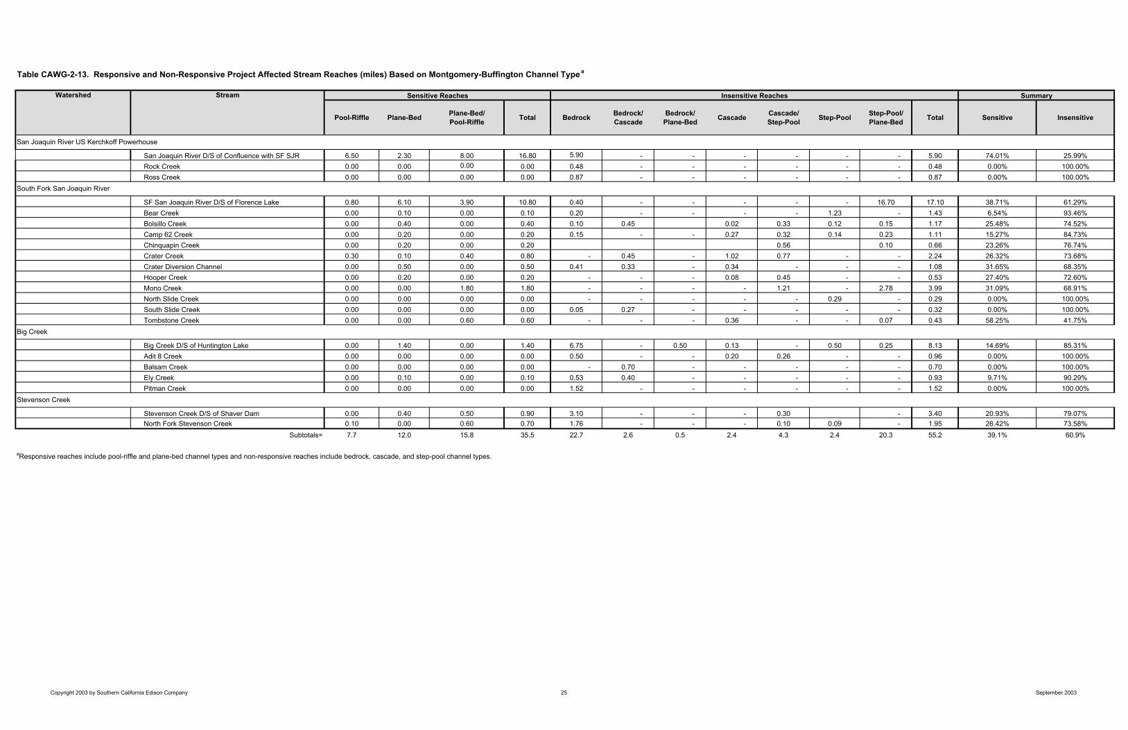
Watershed Stream
Pool-Riffle Plane-Bed Plane-Bed/Pool-Riffle Total Bedrock Bedrock/
CascadeBedrock/
Plane-Bed Cascade Cascade/Step-Pool Step-Pool Step-Pool/
Plane-Bed Total Sensitive Insensitive
San Joaquin River D/S of Confluence with SF SJR 6.50 2.30 8.00 16.80 5.90 - - - - - - 5.90 74.01% 25.99%Rock Creek 0.00 0.00 0.00 0.00 0.48 - - - - - - 0.48 0.00% 100.00%Ross Creek 0.00 0.00 0.00 0.00 0.87 - - - - - - 0.87 0.00% 100.00%
SF San Joaquin River D/S of Florence Lake 0.80 6.10 3.90 10.80 0.40 - - - - - 16.70 17.10 38.71% 61.29%Bear Creek 0.00 0.10 0.00 0.10 0.20 - - - - 1.23 - 1.43 6.54% 93.46%Bolsillo Creek 0.00 0.40 0.00 0.40 0.10 0.45 0.02 0.33 0.12 0.15 1.17 25.48% 74.52%Camp 62 Creek 0.00 0.20 0.00 0.20 0.15 - - 0.27 0.32 0.14 0.23 1.11 15.27% 84.73%Chinquapin Creek 0.00 0.20 0.00 0.20 0.56 0.10 0.66 23.26% 76.74%Crater Creek 0.30 0.10 0.40 0.80 - 0.45 - 1.02 0.77 - - 2.24 26.32% 73.68%Crater Diversion Channel 0.00 0.50 0.00 0.50 0.41 0.33 - 0.34 - - - 1.08 31.65% 68.35%Hooper Creek 0.00 0.20 0.00 0.20 - - - 0.08 0.45 - - 0.53 27.40% 72.60%Mono Creek 0.00 0.00 1.80 1.80 - - - - 1.21 - 2.78 3.99 31.09% 68.91%North Slide Creek 0.00 0.00 0.00 0.00 - - - - - 0.29 - 0.29 0.00% 100.00%South Slide Creek 0.00 0.00 0.00 0.00 0.05 0.27 - - - - - 0.32 0.00% 100.00%Tombstone Creek 0.00 0.00 0.60 0.60 - - - 0.36 - - 0.07 0.43 58.25% 41.75%
Big Creek D/S of Huntington Lake 0.00 1.40 0.00 1.40 6.75 - 0.50 0.13 - 0.50 0.25 8.13 14.69% 85.31%Adit 8 Creek 0.00 0.00 0.00 0.00 0.50 - - 0.20 0.26 - - 0.96 0.00% 100.00%Balsam Creek 0.00 0.00 0.00 0.00 - 0.70 - - - - - 0.70 0.00% 100.00%Ely Creek 0.00 0.10 0.00 0.10 0.53 0.40 - - - - - 0.93 9.71% 90.29%Pitman Creek 0.00 0.00 0.00 0.00 1.52 - - - - - - 1.52 0.00% 100.00%
Stevenson Creek D/S of Shaver Dam 0.00 0.40 0.50 0.90 3.10 - - - 0.30 - 3.40 20.93% 79.07%North Fork Stevenson Creek 0.10 0.00 0.60 0.70 1.76 - - - 0.10 0.09 - 1.95 26.42% 73.58%
Subtotals= 7.7 12.0 15.8 35.5 22.7 2.6 0.5 2.4 4.3 2.4 20.3 55.2 39.1% 60.9%
aResponsive reaches include pool-riffle and plane-bed channel types and non-responsive reaches include bedrock, cascade, and step-pool channel types.
San Joaquin River US Kerchkoff Powerhouse
South Fork San Joaquin River
Big Creek
Stevenson Creek
Sensitive Reaches Insensitive Reaches Summary
Table CAWG-2-13. Responsive and Non-Responsive Project Affected Stream Reaches (miles) Based on Montgomery-Buffington Channel Typea
Copyright 2003 by Southern California Edison Company 25 September 2003
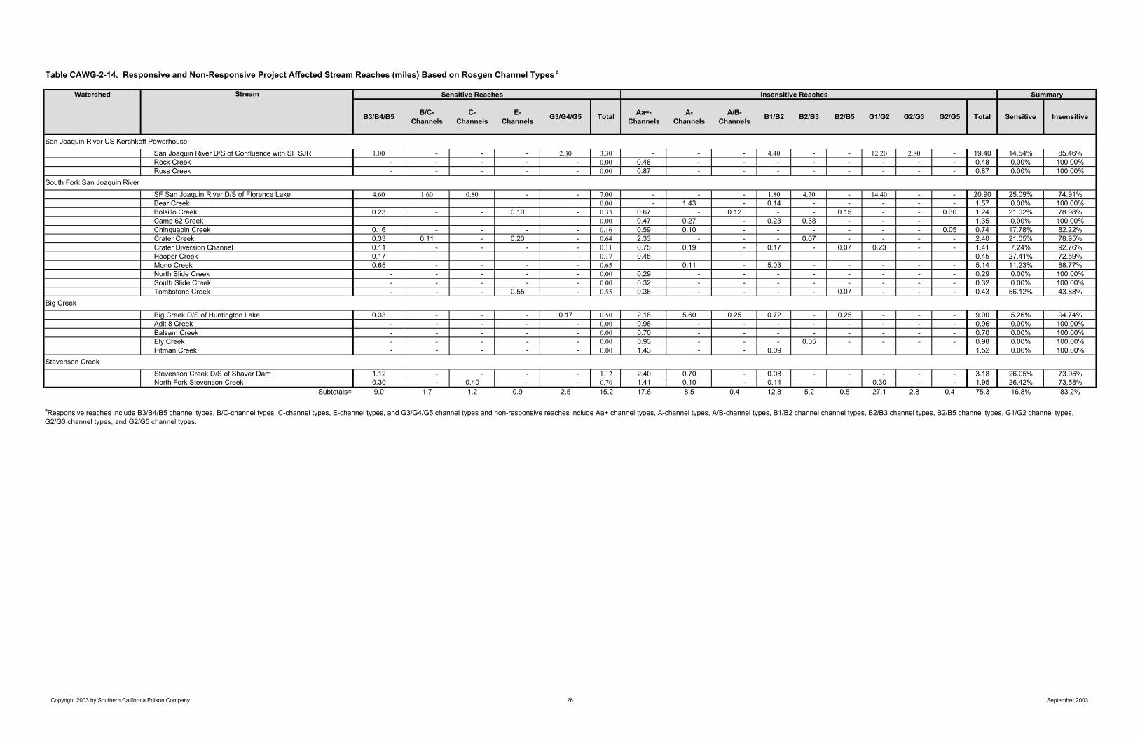
Table CAWG-2-14. Responsive and Non-Responsive Project Affected Stream Reaches (miles) Based on Rosgen Channel Types a
Watershed Stream
B3/B4/B5 B/C-Channels
C-Channels
E-Channels G3/G4/G5 Total Aa+-
ChannelsA-
ChannelsA/B-
Channels B1/B2 B2/B3 B2/B5 G1/G2 G2/G3 G2/G5 Total Sensitive Insensitive
San Joaquin River D/S of Confluence with SF SJR 1.00 - - - 2.30 3.30 - - - 4.40 - - 12.20 2.80 - 19.40 14.54% 85.46%Rock Creek - - - - - 0.00 0.48 - - - - - - - - 0.48 0.00% 100.00%Ross Creek - - - - - 0.00 0.87 - - - - - - - - 0.87 0.00% 100.00%
SF San Joaquin River D/S of Florence Lake 4.60 1.60 0.80 - - 7.00 - - - 1.80 4.70 - 14.40 - - 20.90 25.09% 74.91%Bear Creek 0.00 - 1.43 - 0.14 - - - - - 1.57 0.00% 100.00%Bolsillo Creek 0.23 - - 0.10 - 0.33 0.67 - 0.12 - - 0.15 - - 0.30 1.24 21.02% 78.98%Camp 62 Creek 0.00 0.47 0.27 - 0.23 0.38 - - - 1.35 0.00% 100.00%Chinquapin Creek 0.16 - - - - 0.16 0.59 0.10 - - - - - - 0.05 0.74 17.78% 82.22%Crater Creek 0.33 0.11 - 0.20 - 0.64 2.33 - - - 0.07 - - - - 2.40 21.05% 78.95%Crater Diversion Channel 0.11 - - - - 0.11 0.75 0.19 - 0.17 - 0.07 0.23 - - 1.41 7.24% 92.76%Hooper Creek 0.17 - - - - 0.17 0.45 - - - - - - - - 0.45 27.41% 72.59%Mono Creek 0.65 - - - - 0.65 0.11 - 5.03 - - - - - 5.14 11.23% 88.77%North Slide Creek - - - - - 0.00 0.29 - - - - - - - - 0.29 0.00% 100.00%South Slide Creek - - - - - 0.00 0.32 - - - - - - - - 0.32 0.00% 100.00%Tombstone Creek - - - 0.55 - 0.55 0.36 - - - - 0.07 - - - 0.43 56.12% 43.88%
Big Creek D/S of Huntington Lake 0.33 - - - 0.17 0.50 2.18 5.60 0.25 0.72 - 0.25 - - - 9.00 5.26% 94.74%Adit 8 Creek - - - - - 0.00 0.96 - - - - - - - - 0.96 0.00% 100.00%Balsam Creek - - - - - 0.00 0.70 - - - - - - - - 0.70 0.00% 100.00%Ely Creek - - - - - 0.00 0.93 - - - 0.05 - - - - 0.98 0.00% 100.00%Pitman Creek - - - - - 0.00 1.43 - - 0.09 1.52 0.00% 100.00%
Stevenson Creek D/S of Shaver Dam 1.12 - - - - 1.12 2.40 0.70 - 0.08 - - - - - 3.18 26.05% 73.95%North Fork Stevenson Creek 0.30 - 0.40 - - 0.70 1.41 0.10 - 0.14 - - 0.30 - - 1.95 26.42% 73.58%
Subtotals= 9.0 1.7 1.2 0.9 2.5 15.2 17.6 8.5 0.4 12.8 5.2 0.5 27.1 2.8 0.4 75.3 16.8% 83.2%
South Fork San Joaquin River
Big Creek
Stevenson Creek
aResponsive reaches include B3/B4/B5 channel types, B/C-channel types, C-channel types, E-channel types, and G3/G4/G5 channel types and non-responsive reaches include Aa+ channel types, A-channel types, A/B-channel types, B1/B2 channel channel types, B2/B3 channel types, B2/B5 channel types, G1/G2 channel types, G2/G3 channel types, and G2/G5 channel types.
SummarySensitive Reaches Insensitive Reaches
San Joaquin River US Kerchkoff Powerhouse
Copyright 2003 by Southern California Edison Company 26 September 2003
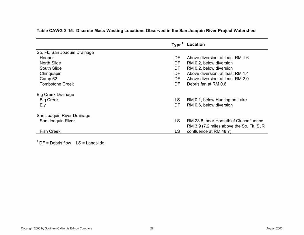
Table CAWG-2-15. Discrete Mass-Wasting Locations Observed in the San Joaquin River Project Watershed
Type1 Location
So. Fk. San Joaquin DrainageHooper DF Above diversion, at least RM 1.6North Slide DF RM 0.2, below diversionSouth Slide DF RM 0.2, below diversionChinquapin DF Above diversion, at least RM 1.4Camp 62 DF Above diversion, at least RM 2.0Tombstone Creek DF Debris fan at RM 0.6
Big Creek DrainageBig Creek LS RM 0.1, below Huntington LakeEly DF RM 0.6, below diversion
San Joaquin River DrainageSan Joaquin River LS RM 23.8, near Horsethief Ck confluence
Fish Creek LSRM 3.9 (7.2 miles above the So. Fk. SJR confluence at RM 48.7)
1 DF = Debris flow LS = Landslide
Copyright 2003 by Southern California Edison Company 27 August 2003

Table CAWG-2-16. Summary of Streambank Erodibility Results from Aerial and Ground Reconnaisance Surveys
Watershed Subwatershed
Total SurveyedStream Miles
Percentageof SurveyedStream Miles
Total Surveyed Stream Miles
Percentageof SurveyedStream Miles
Total Surveyed Stream Miles
Percentageof SurveyedStream Miles
Total Surveyed Stream Miles
Percentage of Surveyed
Stream Miles
San Joaquin River (between Kerchkoff Powerhouse and Confluence with SF San Joaquin River)* NA NA NA NA 22.69 100.0% 0.0 0.0%
Rock Creek 0.43 100.0% 0.00 0.0% 0.48 100.0% 1.0 0.0%
Ross Creek 1.30 100.0% 0.00 0.0% 0.87 100.0% 1.0 0.0%
South Fork San Joaquin River (between confluence with San Joaquin River and Florence Lake) 2.60 66.7% 1.30 33.3% 15.76 56.5% 12.14 43.5%
Bear Creek 3.82 97.4% 0.1 2.6% 1.57 100.0% 0.0 0.0%
Bolsillo Creek 0.46 73.0% 0.17 27.0% 0.67 42.7% 0.90 57.3%
Camp 62 Creek 0.50 100.0% 0.00 0.0% 0.74 54.8% 0.61 45.2%
Chinquapin Creek 0.50 100.0% 0.00 0.0% 0.56 62.2% 0.34 37.8%
Crater Creek 0.40 85.1% 0.07 14.9% 2.33 76.6% 0.71 23.4%
Crater Diversion Channel NA NA NA NA 0.96 61.9% 0.59 38.1%
San Joaquin River
South Fork San Joaquin River
Summary of Streambank Erodibility Results Upstream of Project Facilities
Non-Erodible Erodible
Summary of Streambank Erodibility Results Downstream of Project Facilities
Non-Erodible Erodible
Copyright 2003 by Southern California Edison Company 28 August 2003
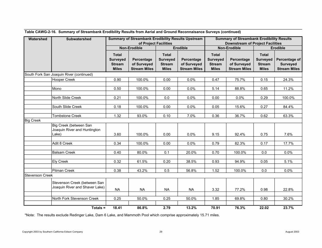
Watershed Subwatershed
Total SurveyedStream Miles
Percentageof SurveyedStream Miles
Total Surveyed Stream Miles
Percentageof SurveyedStream Miles
Total Surveyed Stream Miles
Percentageof SurveyedStream Miles
Total Surveyed Stream Miles
Percentage of Surveyed
Stream Miles
Hooper Creek 0.90 100.0% 0.00 0.0% 0.47 75.7% 0.15 24.3%
Mono 0.50 100.0% 0.00 0.0% 5.14 88.8% 0.65 11.2%
North Slide Creek 0.21 100.0% 0.0 0.0% 0.00 0.0% 0.29 100.0%
South Slide Creek 0.18 100.0% 0.00 0.0% 0.05 15.6% 0.27 84.4%
Tombstone Creek 1.32 93.0% 0.10 7.0% 0.36 36.7% 0.62 63.3%
Big Creek (between San Joaquin River and Huntington Lake) 3.60 100.0% 0.00 0.0% 9.15 92.4% 0.75 7.6%
Adit 8 Creek 0.34 100.0% 0.00 0.0% 0.79 82.3% 0.17 17.7%
Balsam Creek 0.40 80.0% 0.1 20.0% 0.70 100.0% 0.0 0.0%
Ely Creek 0.32 61.5% 0.20 38.5% 0.93 94.9% 0.05 5.1%
Pitman Creek 0.38 43.2% 0.5 56.8% 1.52 100.0% 0.0 0.0%
Stevenson Creek (between San Joaquin River and Shaver Lake) NA NA NA NA 3.32 77.2% 0.98 22.8%
North Fork Stevenson Creek 0.25 50.0% 0.25 50.0% 1.85 69.8% 0.80 30.2%
Totals = 18.41 86.8% 2.79 13.2% 70.91 76.3% 22.02 23.7%
*Note: The results exclude Redinger Lake, Dam 6 Lake, and Mammoth Pool which comprise approximately 15.71 miles.
Stevenson Creek
Big Creek
South Fork San Joaquin River (continued)
Summary of Streambank Erodibility Results Upstream of Project Facilities
Summary of Streambank Erodibility Results Downstream of Project Facilities
Non-Erodible Erodible Non-Erodible Erodible
Table CAWG-2-16. Summary of Streambank Erodibility Results from Aerial and Ground Reconnaisance Surveys (continued)
Copyright 2003 by Southern California Edison Company 29 August 2003
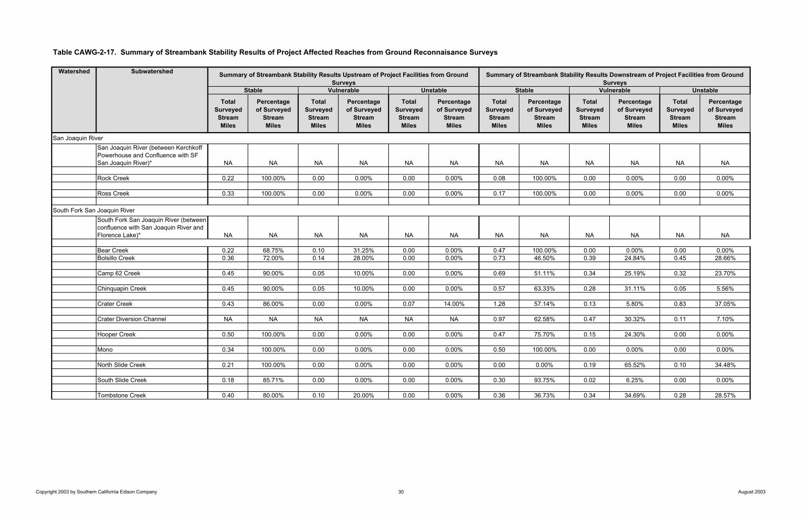
Table CAWG-2-17. Summary of Streambank Stability Results of Project Affected Reaches from Ground Reconnaisance Surveys
Watershed Subwatershed
TotalSurveyedStreamMiles
Percentageof Surveyed
StreamMiles
TotalSurveyedStreamMiles
Percentageof Surveyed
StreamMiles
TotalSurveyedStreamMiles
Percentageof Surveyed
StreamMiles
TotalSurveyedStreamMiles
Percentageof Surveyed
StreamMiles
TotalSurveyedStreamMiles
Percentageof Surveyed
StreamMiles
TotalSurveyedStreamMiles
Percentageof Surveyed
StreamMiles
San Joaquin River (between Kerchkoff Powerhouse and Confluence with SF San Joaquin River)* NA NA NA NA NA NA NA NA NA NA NA NA
Rock Creek 0.22 100.00% 0.00 0.00% 0.00 0.00% 0.08 100.00% 0.00 0.00% 0.00 0.00%
Ross Creek 0.33 100.00% 0.00 0.00% 0.00 0.00% 0.17 100.00% 0.00 0.00% 0.00 0.00%
South Fork San Joaquin River (between confluence with San Joaquin River and Florence Lake)* NA NA NA NA NA NA NA NA NA NA NA NA
Bear Creek 0.22 68.75% 0.10 31.25% 0.00 0.00% 0.47 100.00% 0.00 0.00% 0.00 0.00%Bolsillo Creek 0.36 72.00% 0.14 28.00% 0.00 0.00% 0.73 46.50% 0.39 24.84% 0.45 28.66%
Camp 62 Creek 0.45 90.00% 0.05 10.00% 0.00 0.00% 0.69 51.11% 0.34 25.19% 0.32 23.70%
Chinquapin Creek 0.45 90.00% 0.05 10.00% 0.00 0.00% 0.57 63.33% 0.28 31.11% 0.05 5.56%
Crater Creek 0.43 86.00% 0.00 0.00% 0.07 14.00% 1.28 57.14% 0.13 5.80% 0.83 37.05%
Crater Diversion Channel NA NA NA NA NA NA 0.97 62.58% 0.47 30.32% 0.11 7.10%
Hooper Creek 0.50 100.00% 0.00 0.00% 0.00 0.00% 0.47 75.70% 0.15 24.30% 0.00 0.00%
Mono 0.34 100.00% 0.00 0.00% 0.00 0.00% 0.50 100.00% 0.00 0.00% 0.00 0.00%
North Slide Creek 0.21 100.00% 0.00 0.00% 0.00 0.00% 0.00 0.00% 0.19 65.52% 0.10 34.48%
South Slide Creek 0.18 85.71% 0.00 0.00% 0.00 0.00% 0.30 93.75% 0.02 6.25% 0.00 0.00%
Tombstone Creek 0.40 80.00% 0.10 20.00% 0.00 0.00% 0.36 36.73% 0.34 34.69% 0.28 28.57%
South Fork San Joaquin River
San Joaquin River
Summary of Streambank Stability Results Downstream of Project Facilities from Ground Surveys
Unstable Unstable
Summary of Streambank Stability Results Upstream of Project Facilities from Ground Surveys
Stable Vulnerable Stable Vulnerable
Copyright 2003 by Southern California Edison Company 30 August 2003

Table CAWG-2-17. Summary of Streambank Stability Results of Project Affected Reaches from Ground Reconnaisance Surveys (continued)
Watershed Subwatershed
TotalSurveyedStreamMiles
Percentageof Surveyed
StreamMiles
TotalSurveyedStreamMiles
Percentageof Surveyed
StreamMiles
TotalSurveyedStreamMiles
Percentageof Surveyed
StreamMiles
TotalSurveyedStreamMiles
Percentageof Surveyed
StreamMiles
TotalSurveyedStreamMiles
Percentageof Surveyed
StreamMiles
TotalSurveyedStreamMiles
Percentageof Surveyed
StreamMiles
Big Creek (between San Joaquin River and Huntington Lake) NA NA NA NA NA NA 2.08 69.33% 0.72 24.00% 0.20 6.67%
Adit 8 Creek 0.34 100.00% 0.00 0.00% 0.00 0.00% 0.79 82.29% 0.17 17.71% 0.00 0.00%
Balsam Creek 0.40 80.00% 0.10 20.00% 0.00 0.00% 0.63 90.00% 0.03 4.29% 0.04 5.71%
Ely Creek 0.32 61.54% 0.05 9.62% 0.15 28.85% 0.55 100.00% 0.00 0.00% 0.00 0.00%
Pitman Creek 0.46 92.00% 0.14 28.00% 0.00 0.00% 0.42 100.00% 0.00 0.00% 0.00 0.00%
Stevenson Creek (between San Joaquin River and Shaver Lake) NA NA NA NA NA NA 0.04 10.00% 0.26 65.00% 0.10 25.00%
North Fork Stevenson Creek 0.25 50.00% 0.25 50.00% 0.00 0.00% 0.40 80.00% 0.00 0.00% 0.10 20.00%
Totals = 5.86 83.0% 0.98 13.9% 0.22 3.1% 11.50 66.7% 3.49 20.2% 2.58 15.0%
*Note: Ground surveys were not conducted along the San Joaquin River or the South Fork San Joaquin River.
Big Creek
Stevenson Creek
Summary of Streambank Stability Results Upstream of Project Facilities from Ground Surveys
Summary of Streambank Stability Results Downstream of Project Facilities from Ground Surveys
Stable Vulnerable Unstable Stable Vulnerable Unstable
Copyright 2003 by Southern California Edison Company 31 August 2003
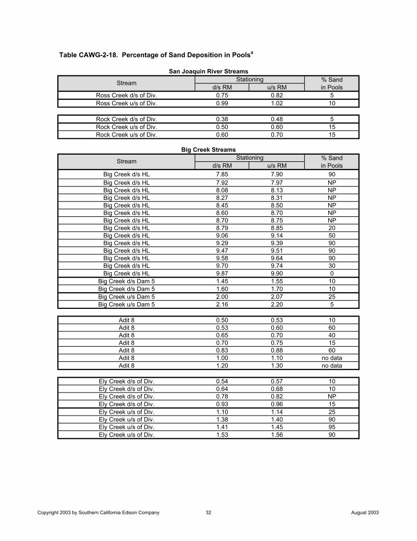
% Sandd/s RM u/s RM in Pools
Ross Creek d/s of Div. 0.75 0.82 5Ross Creek u/s of Div. 0.99 1.02 10
Rock Creek d/s of Div. 0.38 0.48 5Rock Creek u/s of Div. 0.50 0.60 15Rock Creek u/s of Div. 0.60 0.70 15
% Sandd/s RM u/s RM in Pools
Big Creek d/s HL 7.85 7.90 90Big Creek d/s HL 7.92 7.97 NPBig Creek d/s HL 8.08 8.13 NPBig Creek d/s HL 8.27 8.31 NPBig Creek d/s HL 8.45 8.50 NPBig Creek d/s HL 8.60 8.70 NPBig Creek d/s HL 8.70 8.75 NPBig Creek d/s HL 8.79 8.85 20Big Creek d/s HL 9.06 9.14 50Big Creek d/s HL 9.29 9.39 90Big Creek d/s HL 9.47 9.51 90Big Creek d/s HL 9.58 9.64 90Big Creek d/s HL 9.70 9.74 30Big Creek d/s HL 9.87 9.90 0
Big Creek d/s Dam 5 1.45 1.55 10Big Creek d/s Dam 5 1.60 1.70 10Big Creek u/s Dam 5 2.00 2.07 25Big Creek u/s Dam 5 2.16 2.20 5
Adit 8 0.50 0.53 10Adit 8 0.53 0.60 60Adit 8 0.65 0.70 40Adit 8 0.70 0.75 15Adit 8 0.83 0.88 60Adit 8 1.00 1.10 no dataAdit 8 1.20 1.30 no data
Ely Creek d/s of Div. 0.54 0.57 10Ely Creek d/s of Div. 0.64 0.68 10Ely Creek d/s of Div. 0.78 0.82 NPEly Creek d/s of Div. 0.93 0.96 15Ely Creek u/s of Div. 1.10 1.14 25Ely Creek u/s of Div. 1.38 1.40 90Ely Creek u/s of Div. 1.41 1.45 95Ely Creek u/s of Div. 1.53 1.56 90
Table CAWG-2-18. Percentage of Sand Deposition in Poolsa
San Joaquin River Streams
Stream Stationing
Stream
Big Creek StreamsStationing
Copyright 2003 by Southern California Edison Company 32 August 2003
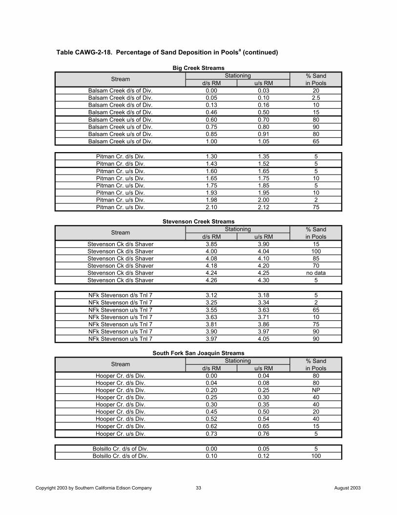
% Sandd/s RM u/s RM in Pools
Balsam Creek d/s of Div. 0.00 0.03 20Balsam Creek d/s of Div. 0.05 0.10 2.5Balsam Creek d/s of Div. 0.13 0.16 10Balsam Creek d/s of Div. 0.46 0.50 15Balsam Creek u/s of Div. 0.60 0.70 80Balsam Creek u/s of Div. 0.75 0.80 90Balsam Creek u/s of Div. 0.85 0.91 80Balsam Creek u/s of Div. 1.00 1.05 65
Pitman Cr. d/s Div. 1.30 1.35 5Pitman Cr. d/s Div. 1.43 1.52 5Pitman Cr. u/s Div. 1.60 1.65 5Pitman Cr. u/s Div. 1.65 1.75 10Pitman Cr. u/s Div. 1.75 1.85 5Pitman Cr. u/s Div. 1.93 1.95 10Pitman Cr. u/s Div. 1.98 2.00 2Pitman Cr. u/s Div. 2.10 2.12 75
% Sandd/s RM u/s RM in Pools
Stevenson Ck d/s Shaver 3.85 3.90 15Stevenson Ck d/s Shaver 4.00 4.04 100Stevenson Ck d/s Shaver 4.08 4.10 85Stevenson Ck d/s Shaver 4.18 4.20 70Stevenson Ck d/s Shaver 4.24 4.25 no dataStevenson Ck d/s Shaver 4.26 4.30 5
NFk Stevenson d/s Tnl 7 3.12 3.18 5NFk Stevenson d/s Tnl 7 3.25 3.34 2NFk Stevenson u/s Tnl 7 3.55 3.63 65NFk Stevenson u/s Tnl 7 3.63 3.71 10NFk Stevenson u/s Tnl 7 3.81 3.86 75NFk Stevenson u/s Tnl 7 3.90 3.97 90NFk Stevenson u/s Tnl 7 3.97 4.05 90
% Sandd/s RM u/s RM in Pools
Hooper Cr. d/s Div. 0.00 0.04 80Hooper Cr. d/s Div. 0.04 0.08 80Hooper Cr. d/s Div. 0.20 0.25 NPHooper Cr. d/s Div. 0.25 0.30 40Hooper Cr. d/s Div. 0.30 0.35 40Hooper Cr. d/s Div. 0.45 0.50 20Hooper Cr. d/s Div. 0.52 0.54 40Hooper Cr. d/s Div. 0.62 0.65 15Hooper Cr. u/s Div. 0.73 0.76 5
Bolsillo Cr. d/s of Div. 0.00 0.05 5Bolsillo Cr. d/s of Div. 0.10 0.12 100
Big Creek Streams
Stream Stationing
StationingSouth Fork San Joaquin Streams
Stevenson Creek Streams
Table CAWG-2-18. Percentage of Sand Deposition in Poolsa (continued)
Stream Stationing
Stream
Copyright 2003 by Southern California Edison Company 33 August 2003
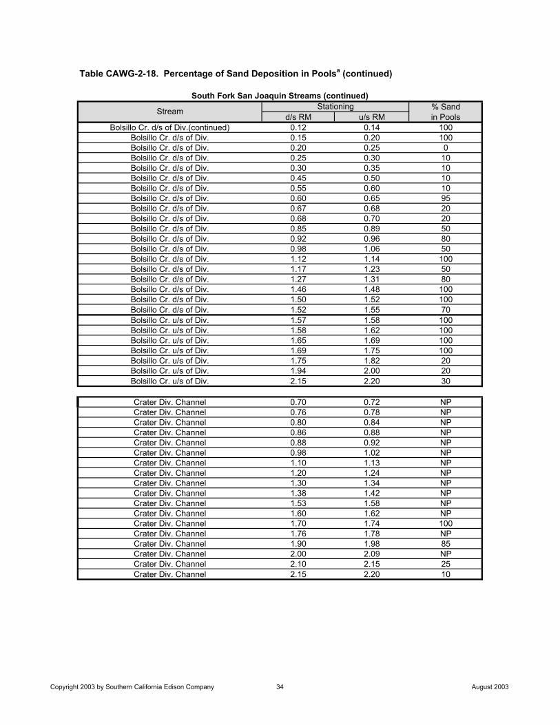
% Sandd/s RM u/s RM in Pools
Bolsillo Cr. d/s of Div.(continued) 0.12 0.14 100Bolsillo Cr. d/s of Div. 0.15 0.20 100Bolsillo Cr. d/s of Div. 0.20 0.25 0Bolsillo Cr. d/s of Div. 0.25 0.30 10Bolsillo Cr. d/s of Div. 0.30 0.35 10Bolsillo Cr. d/s of Div. 0.45 0.50 10Bolsillo Cr. d/s of Div. 0.55 0.60 10Bolsillo Cr. d/s of Div. 0.60 0.65 95Bolsillo Cr. d/s of Div. 0.67 0.68 20Bolsillo Cr. d/s of Div. 0.68 0.70 20Bolsillo Cr. d/s of Div. 0.85 0.89 50Bolsillo Cr. d/s of Div. 0.92 0.96 80Bolsillo Cr. d/s of Div. 0.98 1.06 50Bolsillo Cr. d/s of Div. 1.12 1.14 100Bolsillo Cr. d/s of Div. 1.17 1.23 50Bolsillo Cr. d/s of Div. 1.27 1.31 80Bolsillo Cr. d/s of Div. 1.46 1.48 100Bolsillo Cr. d/s of Div. 1.50 1.52 100Bolsillo Cr. d/s of Div. 1.52 1.55 70Bolsillo Cr. u/s of Div. 1.57 1.58 100Bolsillo Cr. u/s of Div. 1.58 1.62 100Bolsillo Cr. u/s of Div. 1.65 1.69 100Bolsillo Cr. u/s of Div. 1.69 1.75 100Bolsillo Cr. u/s of Div. 1.75 1.82 20Bolsillo Cr. u/s of Div. 1.94 2.00 20Bolsillo Cr. u/s of Div. 2.15 2.20 30
Crater Div. Channel 0.70 0.72 NPCrater Div. Channel 0.76 0.78 NPCrater Div. Channel 0.80 0.84 NPCrater Div. Channel 0.86 0.88 NPCrater Div. Channel 0.88 0.92 NPCrater Div. Channel 0.98 1.02 NPCrater Div. Channel 1.10 1.13 NPCrater Div. Channel 1.20 1.24 NPCrater Div. Channel 1.30 1.34 NPCrater Div. Channel 1.38 1.42 NPCrater Div. Channel 1.53 1.58 NPCrater Div. Channel 1.60 1.62 NPCrater Div. Channel 1.70 1.74 100Crater Div. Channel 1.76 1.78 NPCrater Div. Channel 1.90 1.98 85Crater Div. Channel 2.00 2.09 NPCrater Div. Channel 2.10 2.15 25Crater Div. Channel 2.15 2.20 10
South Fork San Joaquin Streams (continued)
Stream Stationing
Table CAWG-2-18. Percentage of Sand Deposition in Poolsa (continued)
Copyright 2003 by Southern California Edison Company 34 August 2003
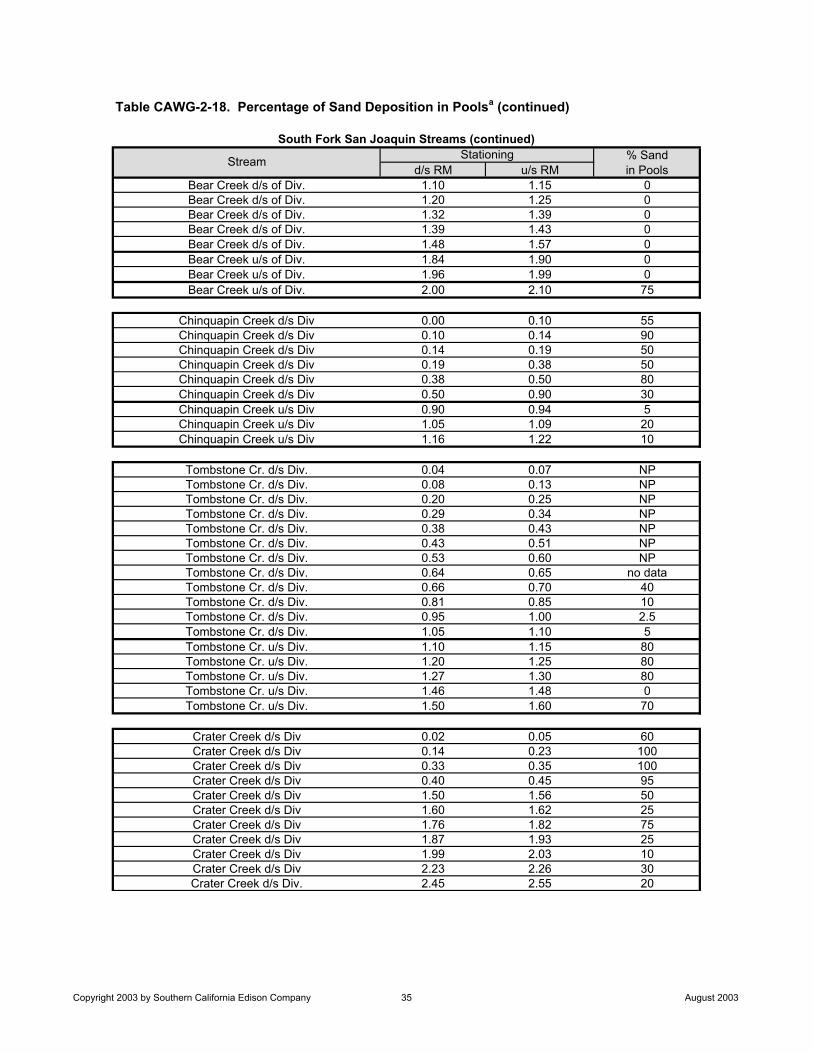
% Sandd/s RM u/s RM in Pools
Bear Creek d/s of Div. 1.10 1.15 0Bear Creek d/s of Div. 1.20 1.25 0Bear Creek d/s of Div. 1.32 1.39 0Bear Creek d/s of Div. 1.39 1.43 0Bear Creek d/s of Div. 1.48 1.57 0Bear Creek u/s of Div. 1.84 1.90 0Bear Creek u/s of Div. 1.96 1.99 0Bear Creek u/s of Div. 2.00 2.10 75
Chinquapin Creek d/s Div 0.00 0.10 55Chinquapin Creek d/s Div 0.10 0.14 90Chinquapin Creek d/s Div 0.14 0.19 50Chinquapin Creek d/s Div 0.19 0.38 50Chinquapin Creek d/s Div 0.38 0.50 80Chinquapin Creek d/s Div 0.50 0.90 30Chinquapin Creek u/s Div 0.90 0.94 5Chinquapin Creek u/s Div 1.05 1.09 20Chinquapin Creek u/s Div 1.16 1.22 10
Tombstone Cr. d/s Div. 0.04 0.07 NPTombstone Cr. d/s Div. 0.08 0.13 NPTombstone Cr. d/s Div. 0.20 0.25 NPTombstone Cr. d/s Div. 0.29 0.34 NPTombstone Cr. d/s Div. 0.38 0.43 NPTombstone Cr. d/s Div. 0.43 0.51 NPTombstone Cr. d/s Div. 0.53 0.60 NPTombstone Cr. d/s Div. 0.64 0.65 no dataTombstone Cr. d/s Div. 0.66 0.70 40Tombstone Cr. d/s Div. 0.81 0.85 10Tombstone Cr. d/s Div. 0.95 1.00 2.5Tombstone Cr. d/s Div. 1.05 1.10 5Tombstone Cr. u/s Div. 1.10 1.15 80Tombstone Cr. u/s Div. 1.20 1.25 80Tombstone Cr. u/s Div. 1.27 1.30 80Tombstone Cr. u/s Div. 1.46 1.48 0Tombstone Cr. u/s Div. 1.50 1.60 70
Crater Creek d/s Div 0.02 0.05 60Crater Creek d/s Div 0.14 0.23 100Crater Creek d/s Div 0.33 0.35 100Crater Creek d/s Div 0.40 0.45 95Crater Creek d/s Div 1.50 1.56 50Crater Creek d/s Div 1.60 1.62 25Crater Creek d/s Div 1.76 1.82 75Crater Creek d/s Div 1.87 1.93 25Crater Creek d/s Div 1.99 2.03 10Crater Creek d/s Div 2.23 2.26 30Crater Creek d/s Div. 2.45 2.55 20
South Fork San Joaquin Streams (continued)
Stream Stationing
Table CAWG-2-18. Percentage of Sand Deposition in Poolsa (continued)
Copyright 2003 by Southern California Edison Company 35 August 2003
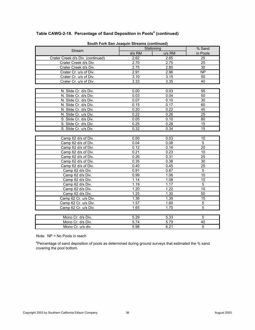
% Sandd/s RM u/s RM in Pools
Crater Creek d/s Div. (continued) 2.62 2.65 25Crater Creek d/s Div. 2.70 2.75 25Crater Creek d/s Div. 2.75 2.85 30Crater Cr. u/s of Div. 2.91 2.96 NPCrater Cr. u/s of Div. 3.10 3.15 50Crater Cr. u/s of Div. 3.33 3.35 40
N. Slide Cr. d/s Div. 0.00 0.03 95N. Slide Cr. d/s Div. 0.03 0.04 50N. Slide Cr. d/s Div. 0.07 0.10 30N. Slide Cr. d/s Div. 0.15 0.17 60N. Slide Cr. d/s Div. 0.20 0.22 45N. Slide Cr. u/s Div. 0.22 0.26 25S. Slide Cr. d/s Div. 0.05 0.10 80S. Slide Cr. d/s Div. 0.25 0.28 15S. Slide Cr. u/s Div. 0.32 0.34 15
Camp 62 d/s of Div. 0.00 0.03 10Camp 62 d/s of Div. 0.04 0.08 5Camp 62 d/s of Div. 0.12 0.16 20Camp 62 d/s of Div. 0.21 0.23 10Camp 62 d/s of Div. 0.26 0.31 25Camp 62 d/s of Div. 0.35 0.38 30Camp 62 d/s of Div. 0.40 0.45 25
Camp 62 d/s Div. 0.91 0.87 5Camp 62 d/s Div. 0.99 1.06 10Camp 62 d/s Div. 1.14 1.08 10Camp 62 d/s Div. 1.19 1.17 5Camp 62 d/s Div. 1.20 1.22 10Camp 62 d/s Div. 1.25 1.30 50
Camp 62 Cr. u/s Div. 1.36 1.39 15Camp 62 Cr. u/s Div. 1.57 1.60 5Camp 62 Cr. u/s Div. 1.65 1.70 5
Mono Cr. d/s Div. 5.29 5.33 5Mono Cr. d/s Div. 5.74 5.79 40Mono Cr. u/s div. 5.98 6.21 5
Note: NP = No Pools in reach
South Fork San Joaquin Streams (continued)
Stream Stationing
aPercentage of sand deposition of pools as determined during ground surveys that estimated the % sand covering the pool bottom.
Table CAWG-2-18. Percentage of Sand Deposition in Poolsa (continued)
Copyright 2003 by Southern California Edison Company 36 August 2003

FIGURES

Placeholder for Figures CAWG 2-1a through 3d
Non-Internet Public Information
These Figures have been removed in accordance with the Commission regulationsat 18 CFR Section 388.112.These Figures are considered Non-Internet Public information and should not beposted on the Internet. This information is provided in Volume 4 of the Applicationfor New License and is identified as “Non-Internet Public” information. Thisinformation may be accessed from the FERC’s Public Reference Room, but is notexpected to be posted on the Commission’s electronic library, except as anindexed item.
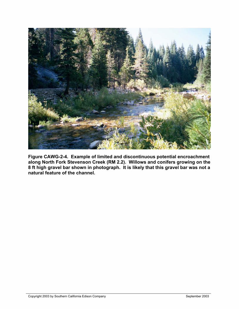
Copyright 2003 by Southern California Edison Company September 2003
Figure CAWG-2-4. Example of limited and discontinuous potential encroachmentalong North Fork Stevenson Creek (RM 2.2). Willows and conifers growing on the8 ft high gravel bar shown in photograph. It is likely that this gravel bar was not anatural feature of the channel.
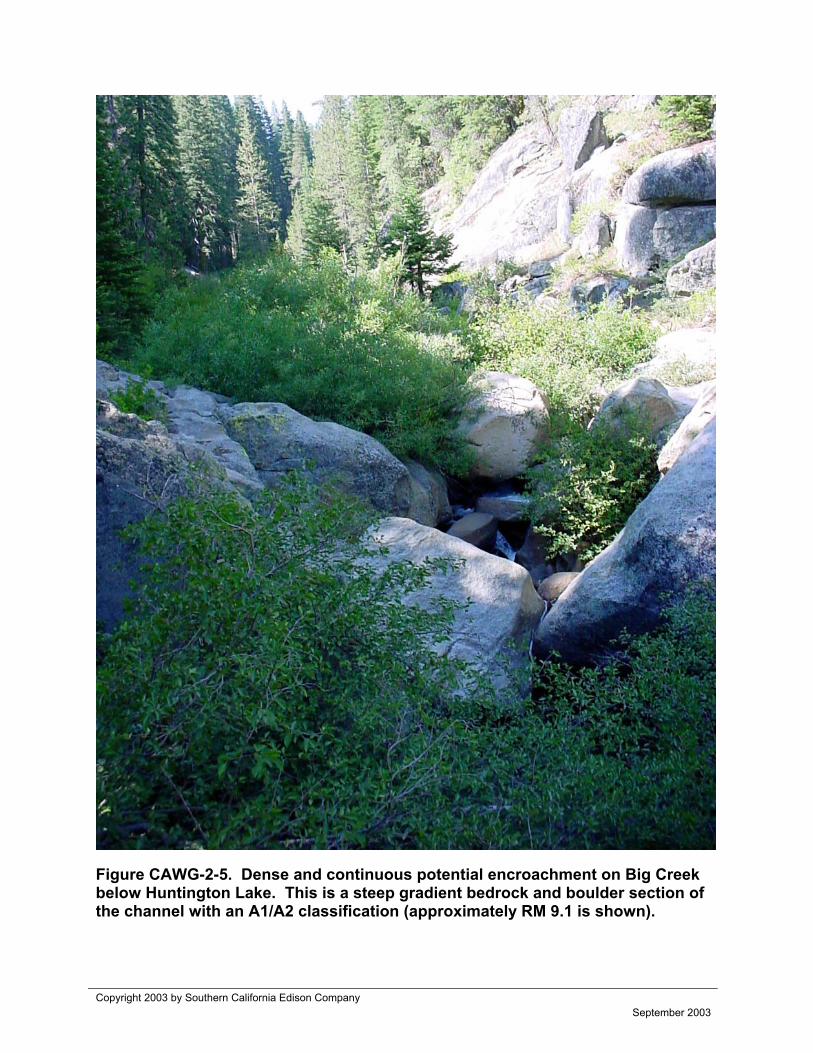
Copyright 2003 by Southern California Edison CompanySeptember 2003
Figure CAWG-2-5. Dense and continuous potential encroachment on Big Creekbelow Huntington Lake. This is a steep gradient bedrock and boulder section ofthe channel with an A1/A2 classification (approximately RM 9.1 is shown).

Placeholder for Figures CAWG 2-6a through 6d
Non-Internet Public Information
These Figures have been removed in accordance with the Commission regulationsat 18 CFR Section 388.112.These Figures are considered Non-Internet Public information and should not beposted on the Internet. This information is provided in Volume 4 of the Applicationfor New License and is identified as “Non-Internet Public” information. Thisinformation may be accessed from the FERC’s Public Reference Room, but is notexpected to be posted on the Commission’s electronic library, except as anindexed item.
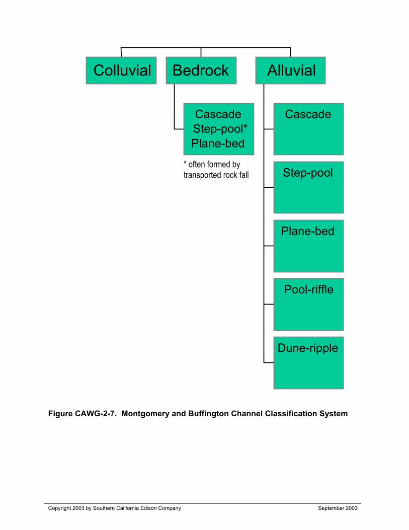
Copyright 2003 by Southern California Edison Company September 2003
Figure CAWG-2-7. Montgomery and Buffington Channel Classification System
Colluvial
CascadeStep-pool*Plane-bed
Bedrock
Cascade
Step-pool
Plane-bed
Pool-riffle
Dune-ripple
Alluvial
* often formed bytransported rock fall

Placeholder for Figures CAWG 2-8a through 8d
Non-Internet Public Information
These Figures have been removed in accordance with the Commission regulationsat 18 CFR Section 388.112.These Figures are considered Non-Internet Public information and should not beposted on the Internet. This information is provided in Volume 4 of the Applicationfor New License and is identified as “Non-Internet Public” information. Thisinformation may be accessed from the FERC’s Public Reference Room, but is notexpected to be posted on the Commission’s electronic library, except as anindexed item.
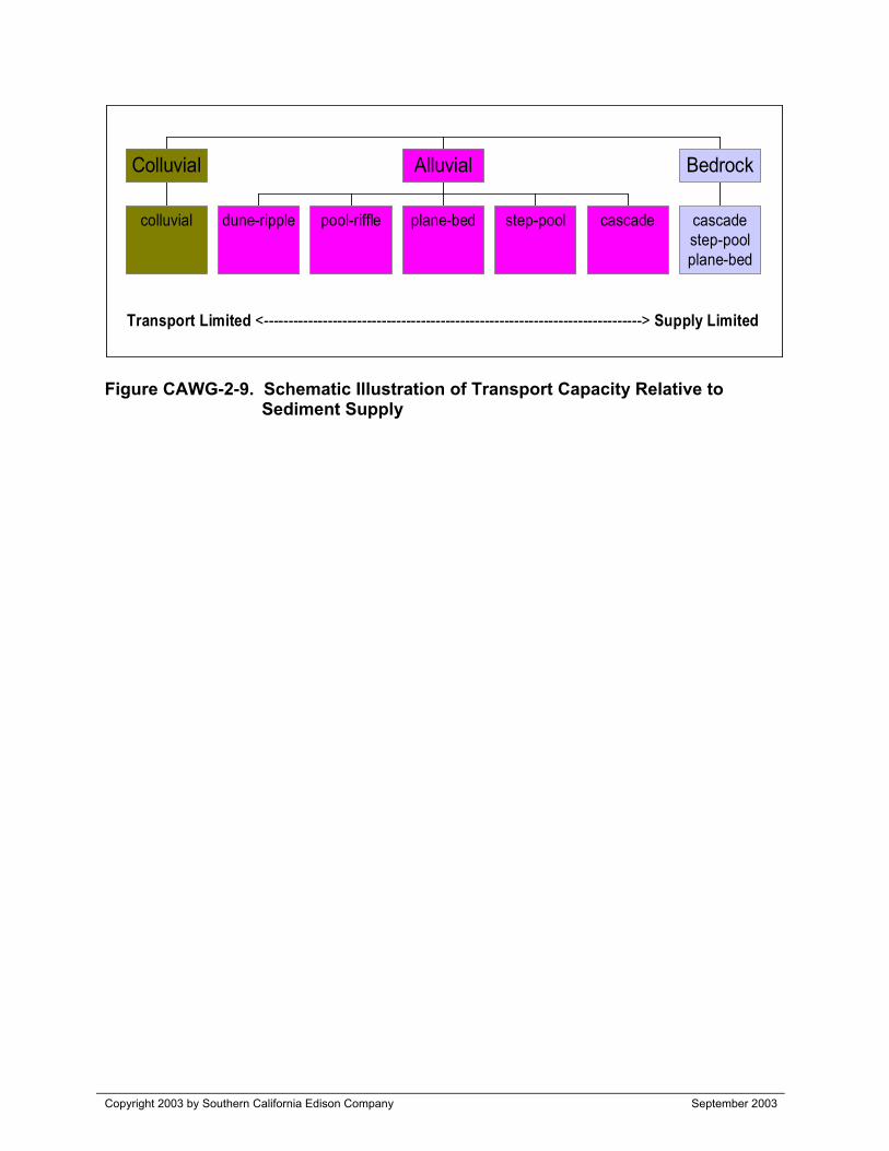
Copyright 2003 by Southern California Edison Company September 2003
Figure CAWG-2-9. Schematic Illustration of Transport Capacity Relative toSediment Supply
Transport Limited <-----------------------------------------------------------------------------> Supply Limited
colluvial
Colluvial
dune-ripple pool-riffle plane-bed step-pool cascade
Alluvial
cascadestep-poolplane-bed
Bedrock
APPENDIX A
Compilation of Photographs Collected During 2002 Ground Surveys

Placeholder for Appendix A
APPENDIX B
Level I Geomorphic Classification andCandidate Reference Reach Assessment
(All tables, figures, and readme files from the CDwere distributed to the CAWG on June 2002)
Combined Aquatics Working Group CAWG-2 Geomorphology
APPENDIX B
BIG CREEK LEVEL I GEOMORPHIC CLASSIFICATIONand
CANDIDATE REFERENCE REACH ASSESSMENT
Copyright 2003 by Southern California Edison Company B-1 September 2003
1.0 Information Provided on Disk
The included files provide the Rosgen Level I geomorphic classification for project streams andcandidate reference streams in the Big Creek Watershed. The results and supporting data arepresented in three summary tables, and a series of graphic plots. In addition, there is an interactivewatershed map. The map uses the same river mile stationing provided in the tables and graphs.A given reach of stream can be located on the watershed map using the upstream and downstreamriver stationing appearing in the tables and/or graphs. The tables, graphs, and maps provided forthis appendix are:
(1) Geomorphic Watershed Parameters (file: BC_geomorph_watersheds.pdf)(2) Geomorphic Reach Parameters (file: BC_geomorph_reaches.pdf)(3) Geomorphic Candidate Reference Reaches (file: BC_geomorph_references.pdf)(4) Stream Profile-Valley Width (folder: Stream_Profiles)(5) Stream Reach Map (file: INDEX_MAP.pdf)(NOTE: Stream profile graphs and interactive maps were provided digitally to the CAWGJune 2002. They are available upon request.)
The purpose and intended use of the Level I classification and reference reach results is discussedbelow in Section 2.0. A detailed description of the type of data included in each of the tables,graphs, and map is provided in section 3.0.
2.0 Purpose and Use of Level I Classification and Reference Reach Results
The Level I stream classification and candidate reference reach assessment fulfills three purposes:
(a) provides essential input for Level 1.5 classification of project-affected streams(b) provides essential geomorphic information for identifying stream reaches most likely
to be adversely affected by project operations(c) identifies candidate reference reaches that may later be compared to project streams to
assist with characterizing and quantifying project influences
The Rosgen Level I classification data for all project-affected streams will be validated and, asappropriate, revised to determine a Level 1.5 classification based on field surveys to be conductedduring summer 2002. The Rosgen Level I classification data for the candidate reference reacheswill not be field validated unless the candidate reference reach is chosen for quantitative analysis.
A given reference reach may be used, if deemed suitable, to assess project effects and will beselected from the pool of candidate reference reaches after the field surveys of project-affectedreaches are completed. Field inspection of channel morphology and surrounding land-use forcandidate reaches will be completed before recommending to the CAWG that a particularcandidate reference stream be used as a basis for quantitative comparison or assessment to identifyproject related effects. The CAWG will participate in selecting reference reach(es).
Combined Aquatics Working Group CAWG-2 Geomorphology
APPENDIX B (continued)
Copyright 2003 by Southern California Edison Company B-2 September 2003
3.0 Description of Data Provided in Reference Reach and Level I Tables and Graphs
3.1 Geomorphic Watershed CharacteristicsThe Big Creek Project Watersheds and Sub-Watersheds table displays various watershed-scaleparameters useful for describing and comparing the geomorphic characteristics of the major basinsand sub-basins of the Big Creek project area. In addition to all of the Big Creek project affectedstreams, the table includes characteristics for numerous other non-project streams in the upper SanJoaquin River watershed. Sub-watersheds with streams that are not regulated by project operationswere selected for analysis because of their potential to serve as geomorphic reference sites. Thetable is organized in a hierarchy that begins with the highest order streams progressing upstream tothe lowest order streams in the upper reaches of the project watershed. The general order ofsequence in the table is: 1) San Joaquin River (SJR) beginning at Powerhouse 4, 2) StevensonCreek, 3) Big Creek, 4) SJR between Big Creek and the South Fork San Joaquin River (SFSJR), 5)SFSJR, and 6) SJR upstream of the SFSJR, including the Middle and North Forks of the SJR.
The first two columns of the table list the major watersheds and sub-watersheds analyzed. A seriesof watershed variables were calculated for each entry in the table. The following is a description ofthe watershed variables:
Project Reach Code: Lists whether stream segments for a particular watershed are unaltered (U),flow augmented (A), or bypassed due to project facilities. The bypassed stream segments aredescribed as; small tributary bypasses (S), moderate tributary bypasses (M), or large bypasses (L).In some instances, more than one code is listed for a particular entry, such as when a streamsegment extends from a project reach into a non-project reach. Information for project reach codeswas obtained from the Project Nexus Matrix, S. Rowan, SCE, November 2000.
• Stream Order: The Strahler method was used to identify stream order. In cases where streams were shown as intermittent on USGS topographic maps, a stream order of zero was assigned.
• Drainage Area: Drainage area was delineated in a GIS format utilizing US Geological Survey (USGS) 7.5-minute, 10-meter resolution Digital Elevation Models (DEMs) that covered the entire watershed area. DEMs are a digital representation of the topography depicted on traditional 7.5-minute USGS quadrangle map. When possible, the drainage area calculations derived from the DEM analysis were compared with values for drainage area reported by the USGS. Results from such comparisons showed nearly identical values.
• Elevation Values: Minimum and maximum elevations were calculated within a GIS format, utilizing the DEMs. Minimum and maximum elevations correspond to the channel invert at it’s downstream confluence, and the watershed crest, respectively. Elevation range is simply the difference between maximum and minimum elevations. The Median Zone category, also determined from DEM analysis, reports the median elevation zone for a given watershed. For example, a Median Zone value of eight is defined as a median elevation of 8,000 to 9,000 ft.
• Aspect: Watershed aspect was calculated from the DEM data, and is reported in one of eight azimuth directions (N, NE, E, SE, S, SW, W, and NW). The Primary and Secondary Aspects
Combined Aquatics Working Group CAWG-2 Geomorphology
APPENDIX B (continued)
Copyright 2003 by Southern California Edison Company B-3 September 2003
are the azimuth directions associated with the two highest percentages, respectively, within agiven watershed. Flat-water areas are indicated with an aspect value of zero.
• Median Hillslope Class: Watershed hillslope gradient was generated from DEM analysis. The median hillslope gradient is reported as a percent, and is grouped into one of seven slope categories (0-1, 1-5, 5-10, 10-25, 25-50, 50-100, and >100).
• Geology: The geology data is based on the 1:750,000 Geologic Map of California, distributed in GIS format on CD-ROM (Source data modified from, Division of Mines and Geology, CD-ROM 2000-007 (2000), GIS Data for the Geologic Map of California). Geologic
types derived from the source data are grouped into 5 categories:
1) Glacially eroded granitic rock1a) Glacially eroded granitic and metamorphic rocks
2) Glacial till deposits3) Non-glaciated granitic rock
4) Non-glaciated metamorphic rock
The Dominant Geology / Landform Process category is the predominant geologic type for a givenwatershed. Sub-dominant Geology / Landform Processes is indicated only in cases when a secondgeologic type accounts for at least 20 percent of the watershed area.
Italicized values in the table refers to data that was derived from hardcopy maps, rather than GISanalysis.
3.2 Geomorphic Reach ParametersThe Big Creek Project Area Geomorphic Reaches table includes data for various geomorphicparameters at both the watershed and stream reach scales. Nearly all of the geomorphic data withinthe table was generated using GIS analysis that incorporated DEMs and 7.5-minute USGStopographic quadrangles. This table summarizes data for all project affected stream reaches, andalso for stream reaches and tributaries unaffected by project operations. The criteria for decidingwhich non-project stream reaches to include in the table was based in part on their size, locationwithin the Big Creek project watershed, and potential to serve as a reference stream. While not allnamed streams in the project watershed are included in the table, a significant effort was made togather geomorphic information on as many streams as was feasible. Over forty different streamsegments are identified as candidate reference reaches, providing a relatively large pool ofcandidate reference streams for consideration and selection. In several instances, preliminarygeomorphic data (i.e. stream profile and drainage area) collected for a non-project stream indicatedthat the stream reach would not likely be suitable as a reference stream. In such cases, no additionalgeomorphic data was collected for the stream reach, as indicated by gray boxes in the table.
The initial step for delineating geomorphic reaches defined in the table was to calculate longitudinalprofile (i.e., channel slope) and valley width for each stream evaluated. Longitudinal profiles werecreated from GIS digitized stream channels and USGS 7.5-minute, 10-meter resolution DigitalElevation Models. The channel centerline was digitized along the entire project-affected reach andcontinuing approximately a few miles upstream of project facilities. On non-project streams (i.e.,potential reference streams), approximately three to five miles of channel centerline, on average,
Combined Aquatics Working Group CAWG-2 Geomorphology
APPENDIX B (continued)
Copyright 2003 by Southern California Edison Company B-4 September 2003
was digitized so that longitudinal profile and valley width could be analyzed. Stream reachgeomorphic attribute data was collected for stream length digitized.
Stream profiles plot the channel bed elevation at intervals of every tenth-mile. Valley width wasdetermined by using the DEMs to locate the transition point from the valley floor to the valleyhillslope. Stream longitudinal profiles and valley width data were examined and were the primaryparameters used to determine the placement of Level I geomorphic reach breaks. However, reachbreaks also took into consideration changes in geology, basin hillslope gradient, drainage area, andother factors such as the presence of road crossings.
The hierarchy of stream reaches presented in the table is the same as that presented in the Big CreekProject Watersheds and Sub-Watersheds table, whereby stream reaches in the first column beginwith the San Joaquin River at Powerhouse 4 and progress upstream through the project watershed,ending at the Middle and North Forks of the SJR. The following is a description of the geomorphicreach parameters contained within the table and the procedures used to calculate their values:
• Project Reach Code: see discussion in Section 3.1
• Stream ID Code: A brief name given to each reach to identify its stream name
• River Stationing: The stream channel is assigned a river station value every tenth of a mile. For each named stream, river stationing begins at the confluence (River Mile 0.0) and extends upstream to the limit of the digitized stream segment. In several cases, stationing is extended through reservoirs in order to maintain a continuous river stationing sequence. Stream reaches are defined by an upstream and downstream river station.
• Cumulative Drainage Area: Values reported in this column refer to the total area draining tothe downstream river station.
• Unit Drainage: Represents the additional, incremental drainage area between the given upstream and downstream river stations.
• Stream Order: see discussion in Section 3.1
• Elevation at Geomorphic Reach Break: Values in this category correspond to the elevation at the downstream river station for a given stream reach.
• Stream Profile Slope: Slope is calculated for the reach from the longitudinal profile.
• Rosgen Level I: Rosgen stream type for this portion of the study is based primarily on channel slope data. Entrenchment ratio, width-depth ratio, and sinuosity, which are also parameters used to define a Level I classification cannot be readily determined from the map and DEM data, therefore slope is the primary determinant for possible Level I stream types. Slope categories and corresponding Rosgen channel type is displayed in the table below. There are overlapping slope categories that define the same stream type, so that more than one channel type may be listed in the Big Creek Project Area Geomorphic Reaches table for a
given channel segment. The Rosgen Level I column lists all potential stream types for the reach based on the slope parameter.

Combined Aquatics Working Group CAWG-2 Geomorphology
APPENDIX B (continued)
Copyright 2003 by Southern California Edison Company B-5 September 2003
Channel Slope (%)Level I
Rosgen TypeLower Limit Upper Limit
Aa+ > 10 -A 4 10B <2 10C <0.1 4E <2 4F <2 4G <2 4
• Watershed Crest Elevation: The peak elevation in the drainage defined for the downstreamriver station of the given reach.
• Valley Width: Valley width was measured every two-tenths of a mile along the channel. Largevalley widths were usually generated by the GIS analysis at the location of project reservoirs,which were excluded in the computation of maximum and average width values.
• Reach and Sub-Basin Geology: Geologic types are discussed in Section 3.1. The reachgeology refers specifically to the geologic type along the defined stream reach (i.e., between theupstream and downstream river mile stations). The reach geology may be different from thatdetermined for the drainage basin as a whole.
Italicized values in the tables refer to data that was derived from hardcopy maps, rather than GISanalysis.
3.3 Geomorphic Reference Reaches
The Candidate Geomorphic Reference Reaches table lists the geomorphic reaches of project-affected streams and compares them to possible candidate reference streams. Candidate referencestreams were identified using the Big Creek Project Watersheds and Sub-Watersheds and Big CreekProject Area Geomorphic Reaches tables to search for non-project stream reaches with reasonablysimilar geomorphic characteristics as the project affected reaches. Similarities in stream profile anddrainage area were first sought in the initial phase of the search. After finding preliminary referencestream reaches that had comparable stream profiles and drainage areas to the project-affectedstreams, additional geomorphic attributes were analyzed to selectively reduce the number of non-project stream reaches that could serve as candidate reference reaches.
Several potential reference reaches were usually considered for each project reach, but the tableonly displays those candidate reference reaches that were most similar to the project streams. Acandidate reference reach can be on the same stream as the project affected reach (i.e., above allproject facilities), or it may be in a different drainage basin. First priority was given to evaluatingpotential references from the same stream, above all diversions. However, if no suitable referencematches could be found on the same stream, then other basins were considered.
A series of 10 geomorphic variables are listed in the table, from stream profile to basin hillslope.For each of these categories, a rating is assigned, indicating that the reference stream is similar
Combined Aquatics Working Group CAWG-2 Geomorphology
APPENDIX B (continued)
Copyright 2003 by Southern California Edison Company B-6 September 2003
(“+”) or dissimilar (“-“) to the project stream for that particular category. The hierarchy of streamreaches presented in the table is the same as that presented in the Big Creek Project Watersheds andSub-Watersheds and Big Creek Project Area Geomorphic Reaches tables. Note that some of theproject reaches listed in the table have more than one candidate reference stream For exampleStevenson Creek downstream (DS) Shaver Lake (RM 2.43 – 4.23), is listed twice, once with thecandidate reference stream located on Stevenson Creek above Shaver Lake (RM .3-11.5), and oncewith Kaiser Creek (RM .45-3.45) listed as the candidate reference stream. The following is adescription of the Candidate Geomorphic Reference Reaches table, including the guidelines used todetermine the ratings of similarity or dissimilarity:
• Project Reach Code: see discussion Section 3.1
• River Stationing: see discussion Section 3.2
• Rosgen Level I: see discussion Section 3.2
• Above Diversion?: If Yes, than the reference reach in on the same stream as the project reach, but above all project facilities. If , No, then the reference reach is located on another stream.
• Other Sub-basin?: Lists the sub-basin for a reference reach that is not located on the same stream as the project reach.
• River Stationing: Indicates the downstream and upstream river station that delineates the reference reach.
Comparison of Project-Affected Streams and Candidate Reference Reach GeomorphicCharacteristics
A discussion of comparative ratings for similarity (“+”) and dissimilarity (“-“) is provided for eachof the 10 geomorphic parameters:
• Stream Profile / Rosgen Level I Stream Type: If candidate reference and project-affected streams have the same Rosgen Level I classification, based on slope categories, then a “+” rating is assigned. If candidate reference and project-affected streams fall into different Rosgen Level I classifications, then a “-“ rating is assigned.
• Drainage Area: If the drainage areas are within a factor of two, then a plus is given. Drainageareas different by more than a factor of two are assigned a minus.
• Elevation at Geomorphic Reach Break: If the downstream reach elevation of the project and reference stream is within 1,000 ft, then a plus is assigned. Differences greater than 1,000 ft are assigned a minus rating.
• Maximum Basin Elevation: If the maximum elevation of the project and reference reach upstream drainage area is within 1,000 ft of each other, than a plus is given.
• Stream Order: A plus is given to streams that have the same order. A plus is also assigned fordifferences up to one stream order for 1 versus a stream order 2, or a stream order 2 versus anorder 3. Any differences in stream order above a 3 are given a minus. This is based on the
Combined Aquatics Working Group CAWG-2 Geomorphology
APPENDIX B (continued)
Copyright 2003 by Southern California Edison Company B-7 September 2003
recognition that differences in magnitude between an order 1 and 2, or order 2 and a 3, are notas great as differences in stream orders of 3 or above. Stream orders of 1 or greater comparedwith intermittent streams were assigned a minus.
• Reach Geology: If the primary reach geology is the same, a plus designation is assigned. A negative designation is given if the primary geology is different. Secondary geology values are not considered in this table.
• Basin Geology: If basin primary geology is the same, a plus designation is assigned. Secondary geology values are not considered in this table.
• Basin Aspect: If primary azimuth directions are within 135 degrees of each other, then a plus was assigned.
• Valley Width: If average valley widths are within a factor of two between project-affected and candidate reference streams, then a plus is given. If average valley widths are greater than a factor of two, then a negative rating is assigned.
• Basin Hillslope: A plus rating is assigned if the median basin slope values between the projectand reference stream reach are in the same slope category. If the median basin slope was indifferent categories, then a dissimilar rating (“-“) was assigned.
3.4 Stream Profile-Valley Width Graphic Plots and Level I ClassificationGraphic plots of the longitudinal stream profile and valley width for both project and candidatereference streams. River stationing is plotted on the X-axis, beginning with zero at the downstreamconfluence. Valley width is shown on the primary Y-axis, indicated by aqua blue bars on the graph.The secondary Y-axis plots elevation of the stream channel at a given river station, and is shown bya navy blue line.
Geomorphic reach breaks are defined between red vertical lines with the range of possible RosgenLevel I stream classifications indicated between each reach break. Locations of diversions areshown with navy blue diamonds.
3.5 Stream Reach MapsAny stream reach defined on the tables or longitudinal stream profiles can be located on the mapswhich show the stream stationing. Start by opening the file named INDEX_MAP.pdf. You will seea map of the entire watershed with a grid overlay. This map is 44”x 34” and is suitable for printingto a large-format output device such as a plotter.
On the left side of the screen there is a list of streams featured on the Index Map. Simply click onthe name of the stream on the list, and the map window will zoom to the area of the map containingthat stream channel. Click on the stream itself and you will be presented with a detailedtopographic map of the region surrounding that stream, suitable for output to a desktop printer(must be capable of 11” x 17” format). To return to the main Index Map, use the hand tool to clickon the gray bar at the top of the map that says, “CLICK HERE TO RETURN TO INDEX MAP”.
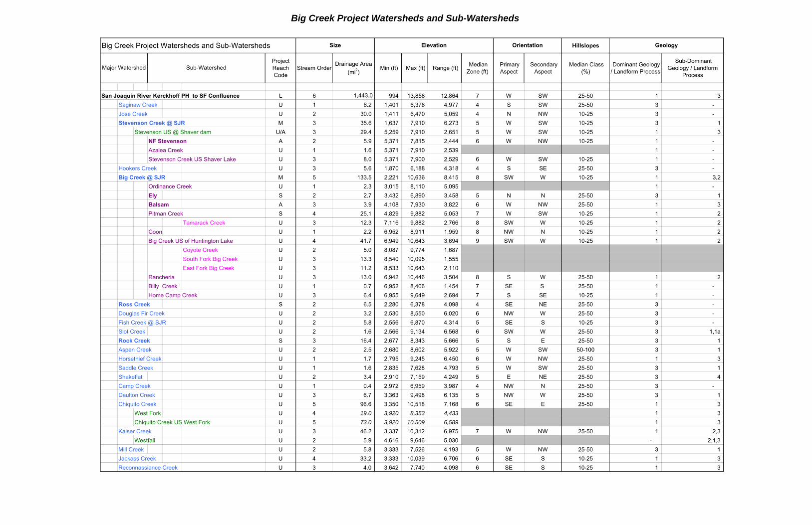
Big Creek Project Watersheds and Sub-Watersheds
Big Creek Project Watersheds and Sub-Watersheds Hillslopes
Project Reach Code
Stream OrderDrainage Area
(mi2) Min (ft) Max (ft) Range (ft)
Median Zone (ft)
Primary Aspect
Secondary Aspect
Median Class (%)
Dominant Geology / Landform Process
Sub-Dominant Geology / Landform
Process
San Joaquin River Kerckhoff PH to SF Confluence L 6 1,443.0 994 13,858 12,864 7 W SW 25-50 1 3
Saginaw Creek U 1 6.2 1,401 6,378 4,977 4 S SW 25-50 3 -
Jose Creek U 2 30.0 1,411 6,470 5,059 4 N NW 10-25 3 -
Stevenson Creek @ SJR M 3 35.6 1,637 7,910 6,273 5 W SW 10-25 3 1
Stevenson US @ Shaver dam U/A 3 29.4 5,259 7,910 2,651 5 W SW 10-25 1 3
NF Stevenson A 2 5.9 5,371 7,815 2,444 6 W NW 10-25 1 -
Azalea Creek U 1 1.6 5,371 7,910 2,539 1 -
Stevenson Creek US Shaver Lake U 3 8.0 5,371 7,900 2,529 6 W SW 10-25 1 -
Hookers Creek U 3 5.6 1,870 6,188 4,318 4 S SE 25-50 3 -
Big Creek @ SJR M 5 133.5 2,221 10,636 8,415 8 SW W 10-25 1 3,2
Ordinance Creek U 1 2.3 3,015 8,110 5,095 1 -
Ely S 2 2.7 3,432 6,890 3,458 5 N N 25-50 3 1
Balsam A 3 3.9 4,108 7,930 3,822 6 W NW 25-50 1 3
Pitman Creek S 4 25.1 4,829 9,882 5,053 7 W SW 10-25 1 2
Tamarack Creek U 3 12.3 7,116 9,882 2,766 8 SW W 10-25 1 2
Coon U 1 2.2 6,952 8,911 1,959 8 NW N 10-25 1 2
Big Creek US of Huntington Lake U 4 41.7 6,949 10,643 3,694 9 SW W 10-25 1 2
Coyote Creek U 2 5.0 8,087 9,774 1,687
South Fork Big Creek U 3 13.3 8,540 10,095 1,555
East Fork Big Creek U 3 11.2 8,533 10,643 2,110
Rancheria U 3 13.0 6,942 10,446 3,504 8 S W 25-50 1 2
Billy Creek U 1 0.7 6,952 8,406 1,454 7 SE S 25-50 1 -
Home Camp Creek U 3 6.4 6,955 9,649 2,694 7 S SE 10-25 1 -
Ross Creek S 2 6.5 2,280 6,378 4,098 4 SE NE 25-50 3 -
Douglas Fir Creek U 2 3.2 2,530 8,550 6,020 6 NW W 25-50 3 -
Fish Creek @ SJR U 2 5.8 2,556 6,870 4,314 5 SE S 10-25 3 -
Slot Creek U 2 1.6 2,566 9,134 6,568 6 SW W 25-50 3 1,1a
Rock Creek S 3 16.4 2,677 8,343 5,666 5 S E 25-50 3 1
Aspen Creek U 2 2.5 2,680 8,602 5,922 5 W SW 50-100 3 1
Horsethief Creek U 1 1.7 2,795 9,245 6,450 6 W NW 25-50 1 3
Saddle Creek U 1 1.6 2,835 7,628 4,793 5 W SW 25-50 3 1
Shakeflat U 2 3.4 2,910 7,159 4,249 5 E NE 25-50 3 4
Camp Creek U 1 0.4 2,972 6,959 3,987 4 NW N 25-50 3 -
Daulton Creek U 3 6.7 3,363 9,498 6,135 5 NW W 25-50 3 1
Chiquito Creek U 5 96.6 3,350 10,518 7,168 6 SE E 25-50 1 3
West Fork U 4 19.0 3,920 8,353 4,433 1 3
Chiquito Creek US West Fork U 5 73.0 3,920 10,509 6,589 1 3
Kaiser Creek U 3 46.2 3,337 10,312 6,975 7 W NW 25-50 1 2,3
Westfall U 2 5.9 4,616 9,646 5,030 - 2,1,3
Mill Creek U 2 5.8 3,333 7,526 4,193 5 W NW 25-50 3 1
Jackass Creek U 4 33.2 3,333 10,039 6,706 6 SE S 10-25 1 3
Reconnassiance Creek U 3 4.0 3,642 7,740 4,098 6 SE S 10-25 1 3
Elevation
Major Watershed
Geology
Sub-Watershed
Size Orientation
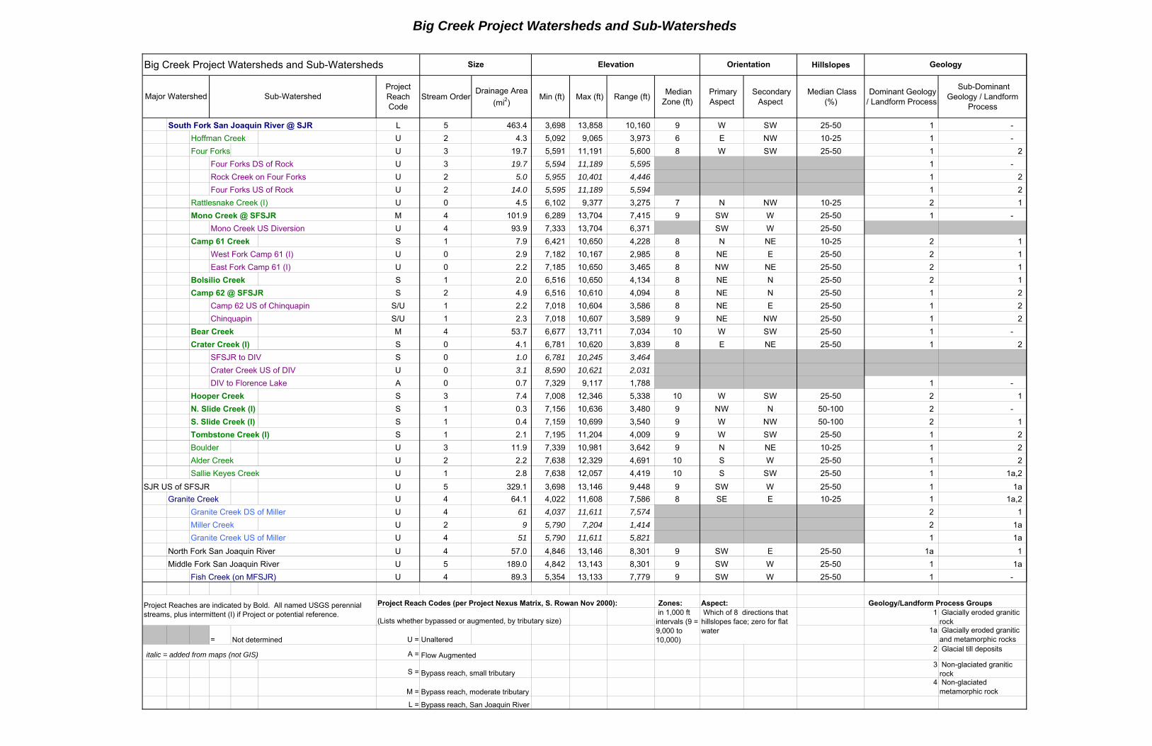
Big Creek Project Watersheds and Sub-Watersheds
Big Creek Project Watersheds and Sub-Watersheds Hillslopes
Project Reach Code
Stream OrderDrainage Area
(mi2) Min (ft) Max (ft) Range (ft)
Median Zone (ft)
Primary Aspect
Secondary Aspect
Median Class (%)
Dominant Geology / Landform Process
Sub-Dominant Geology / Landform
Process
Elevation
Major Watershed
Geology
Sub-Watershed
Size Orientation
South Fork San Joaquin River @ SJR L 5 463.4 3,698 13,858 10,160 9 W SW 25-50 1 -
Hoffman Creek U 2 4.3 5,092 9,065 3,973 6 E NW 10-25 1 -
Four Forks U 3 19.7 5,591 11,191 5,600 8 W SW 25-50 1 2
Four Forks DS of Rock U 3 19.7 5,594 11,189 5,595 1 -
Rock Creek on Four Forks U 2 5.0 5,955 10,401 4,446 1 2
Four Forks US of Rock U 2 14.0 5,595 11,189 5,594 1 2
Rattlesnake Creek (I) U 0 4.5 6,102 9,377 3,275 7 N NW 10-25 2 1
Mono Creek @ SFSJR M 4 101.9 6,289 13,704 7,415 9 SW W 25-50 1 -
Mono Creek US Diversion U 4 93.9 7,333 13,704 6,371 SW W 25-50
Camp 61 Creek S 1 7.9 6,421 10,650 4,228 8 N NE 10-25 2 1
West Fork Camp 61 (I) U 0 2.9 7,182 10,167 2,985 8 NE E 25-50 2 1
East Fork Camp 61 (I) U 0 2.2 7,185 10,650 3,465 8 NW NE 25-50 2 1
Bolsilio Creek S 1 2.0 6,516 10,650 4,134 8 NE N 25-50 2 1
Camp 62 @ SFSJR S 2 4.9 6,516 10,610 4,094 8 NE N 25-50 1 2
Camp 62 US of Chinquapin S/U 1 2.2 7,018 10,604 3,586 8 NE E 25-50 1 2
Chinquapin S/U 1 2.3 7,018 10,607 3,589 9 NE NW 25-50 1 2
Bear Creek M 4 53.7 6,677 13,711 7,034 10 W SW 25-50 1 -
Crater Creek (I) S 0 4.1 6,781 10,620 3,839 8 E NE 25-50 1 2
SFSJR to DIV S 0 1.0 6,781 10,245 3,464
Crater Creek US of DIV U 0 3.1 8,590 10,621 2,031
DIV to Florence Lake A 0 0.7 7,329 9,117 1,788 1 -
Hooper Creek S 3 7.4 7,008 12,346 5,338 10 W SW 25-50 2 1
N. Slide Creek (I) S 1 0.3 7,156 10,636 3,480 9 NW N 50-100 2 -
S. Slide Creek (I) S 1 0.4 7,159 10,699 3,540 9 W NW 50-100 2 1
Tombstone Creek (I) S 1 2.1 7,195 11,204 4,009 9 W SW 25-50 1 2
Boulder U 3 11.9 7,339 10,981 3,642 9 N NE 10-25 1 2
Alder Creek U 2 2.2 7,638 12,329 4,691 10 S W 25-50 1 2
Sallie Keyes Creek U 1 2.8 7,638 12,057 4,419 10 S SW 25-50 1 1a,2
SJR US of SFSJR U 5 329.1 3,698 13,146 9,448 9 SW W 25-50 1 1a
Granite Creek U 4 64.1 4,022 11,608 7,586 8 SE E 10-25 1 1a,2
Granite Creek DS of Miller U 4 61 4,037 11,611 7,574 2 1
Miller Creek U 2 9 5,790 7,204 1,414 2 1a
Granite Creek US of Miller U 4 51 5,790 11,611 5,821 1 1a
North Fork San Joaquin River U 4 57.0 4,846 13,146 8,301 9 SW E 25-50 1a 1
Middle Fork San Joaquin River U 5 189.0 4,842 13,143 8,301 9 SW W 25-50 1 1a
Fish Creek (on MFSJR) U 4 89.3 5,354 13,133 7,779 9 SW W 25-50 1 -
Project Reach Codes (per Project Nexus Matrix, S. Rowan Nov 2000): Zones: Aspect: Geology/Landform Process Groups
(Lists whether bypassed or augmented, by tributary size) 1 Glacially eroded granitic
rock
= U = Unaltered 1a Glacially eroded granitic
and metamorphic rocks
italic = added from maps (not GIS) A = 2 Glacial till deposits
S = 3 Non-glaciated granitic
rock
M = 4 Non-glaciated
metamorphic rock
L = Bypass reach, San Joaquin River
Not determined
Flow Augmented
Bypass reach, moderate tributary
Project Reaches are indicated by Bold. All named USGS perennial streams, plus intermittent (I) if Project or potential reference. in 1,000 ft
intervals (9 = 9,000 to 10,000)
Bypass reach, small tributary
Which of 8 directions that hillslopes face; zero for flat water
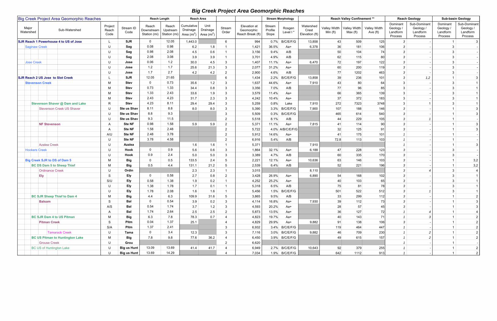
Big Creek Project Area Geomorphic Reaches
Big Creek Project Area Geomorphic Reaches
Project Reach Code
Stream ID Code
Reach Downstream Station (mi)
Reach Upstream
Station (mi)
Cumulative Drainage
Area (mi2)
Unit Drainage
Area (mi2)
Stream Order
Elevation at Geomorphic
Reach Break (ft)
Stream Profile Slope
Rosgen Level I *
Watershed Crest
Elevation (ft)
Valley Width Min (ft)
Valley Width Max (ft)
Valley Width Ave (ft)
Dominant Geology / Landform Process
Sub-Dominant Geology / Landform Process
Dominant Geology / Landform Process
Sub-Dominant Geology / Landform Process
SJR Reach 1 Powerhouse 4 to US of Jose L SJR 0 12.05 1,443.0 6 994 0.7% B/C/E/F/G 13,858 43 509 125 3 - 1 3
Saginaw Creek U Sag 0.08 0.98 6.2 1.8 1 1,421 36.5% Aa+ 6,378 36 181 106 3 - 3 -
U Sag 0.98 2.08 4.5 0.6 1 3,156 9.4% A/B 50 104 74 3 - 3 -
U Sag 2.08 3.08 3.9 3.9 1 3,701 4.9% A/B 62 115 80 3 - 3 -
Jose Creek U Jose 0.06 1.2 30.0 4.5 3 1,407 11.1% Aa+ 6,470 72 197 122 3 - 3 -
U Jose 1.2 1.7 25.6 21.3 3 2,077 31.2% Aa+ 60 200 119 3 - 3 -
U Jose 1.7 2.7 4.2 4.2 2 2,900 4.6% A/B 77 1202 463 3 - 3 -
SJR Reach 2 US Jose to Slot Creek L SJR 12.05 21.65 6 1,434 2.2% B/C/E/F/G 13,858 39 236 101 3 1,2 1 3
Stevenson Creek M Stev 0 0.73 35.6 1.2 3 1,637 44.6% Aa+ 7,910 43 80 64 3 - 3 1
M Stev 0.73 1.33 34.4 0.8 3 3,356 7.0% A/B 77 96 85 3 - 3 1
M Stev 1.33 2.43 33.6 1.9 3 3,579 11.4% Aa+ 66 365 139 3 - 3 1
M Stev 2.43 4.23 31.7 2.3 3 4,242 10.4% Aa+ 37 372 183 3 - 3 1
Stevenson Shaver @ Dam and Lake R Stev 4.23 8.11 29.4 29.4 3 5,259 0.8% Lake 7,910 272 7323 3748 3 1 3 1
Stevenson Creek US Shaver U Ste us Shav 8.11 8.8 8.0 8.0 3 5,390 3.3% B/C/E/F/G 7,900 107 188 146 3 - 1 3
U Ste us Shav 8.8 9.3 3 5,509 0.3% B/C/E/F/G 465 614 540 3 - 1 3
U Ste us Shav 9.3 11.5 2 5,518 8.1% A/B 44 229 105 3 1 1 -
NF Stevenson A Ste NF 0.98 1.58 5.9 5.9 2 5,371 11.1% Aa+ 7,815 41 114 90 3 - 1 3
A Ste NF 1.58 2.48 2 5,722 4.0% A/B/C/E/F/G 32 125 91 3 - 1 3
A/U Ste NF 2.48 3.78 2 5,912 14.6% Aa+ 41 175 101 1 - 1 -
U Ste NF 3.78 4.58 2 6,916 5.4% A/B 72.8 113 103 1 - 1 -
Azalea Creek U Azalea 1.6 1.6 1 5,371 7,910 1 - 1 3
Hookers Creek U Hook 0 0.9 5.6 0.6 3 1,864 32.1% Aa+ 6,188 47 228 123 3 - 3 -
U Hook 0.9 2.4 5.0 5.0 3 3,389 4.7% A/B 60 335 170 3 - 3 -
Big Creek SJR to DS of Dam 5 M Big 0 0.5 133.5 2.4 5 2,221 12.1% Aa+ 10,636 63 146 103 3 - 1 3,2
BC DS Dam 5 to Sheep Thief M Big 0.5 4.4 131.1 21.2 5 2,539 6.4% A/B 52 221 196 3 - 1 3,2
Ordinance Creek U Ordin 2.3 2.3 1 3,015 8,110 3 4 3 4
Ely S Ely 0 0.58 2.7 0.8 2 3,428 26.9% Aa+ 6,890 54 168 102 3 - 3 1
S/U Ely 0.58 1.38 1.9 0.2 1 4,252 25.2% Aa+ 40 103 65 3 - 3 1
U Ely 1.38 1.78 1.7 0.1 1 5,318 6.5% A/B 75 81 78 3 - 3 1
U Ely 1.78 2.08 1.6 1.6 1 5,456 1.5% B/C/E/F/G 501 522 512 3 1 3 1
BC SJR Sheep Thief to Dam 4 M Big 4.4 6.3 109.9 31.6 5 3,865 9.5% A/B 33 299 112 3 - 1 2
Balsam S Bal 0 0.54 3.9 0.2 3 4,114 16.8% Aa+ 7,930 39 112 73 3 - 1 3
A/S Bal 0.54 1.74 3.7 1.2 3 4,593 20.2% Aa+ 28 57 45 3 - 1 3
A Bal 1.74 2.64 2.5 2.5 2 5,873 13.5% Aa+ 36 127 72 1 4 1 4
BC SJR Dam 4 to US Pitman M Big 6.3 7.8 78.3 0.7 4 4,823 19.7% Aa+ 40 143 71 1 3 1 2
Pitman Creek S Pitm 0.04 1.37 25.1 4 4,829 29.9% Aa+ 9,882 91 138 106 3 - 1 2
S/A Pitm 1.37 2.41 3 6,932 3.4% B/C/E/F/G 119 464 447 1 - 1 2
Tamarack Creek U Tama 0 3.4 12.3 3 7,116 3.0% B/C/E/F/G 9,882 46 709 230 1 2 1 2
BC US Pitman to Huntington Lake M Big 7.8 9.8 77.6 36.2 4 6,450 3.9% B/C/E/F/G 49 615 157 1 2 1 2
Grouse Creek U Grou 2 6,620 1 - 1 -
BC US of Huntington Lake U Big us Hunt 13.09 13.69 41.4 41.7 4 6,949 2.7% B/C/E/F/G 10,643 92 379 255 1 - 1 2
U Big us Hunt 13.69 14.29 4 7,034 1.9% B/C/E/F/G 642 1112 913 1 - 1 2
Sub-Watershed
Sub-basin GeologyReach Geology
Major Watershed
Reach Valley Confinement **Reach Length Reach Area Stream Morphology
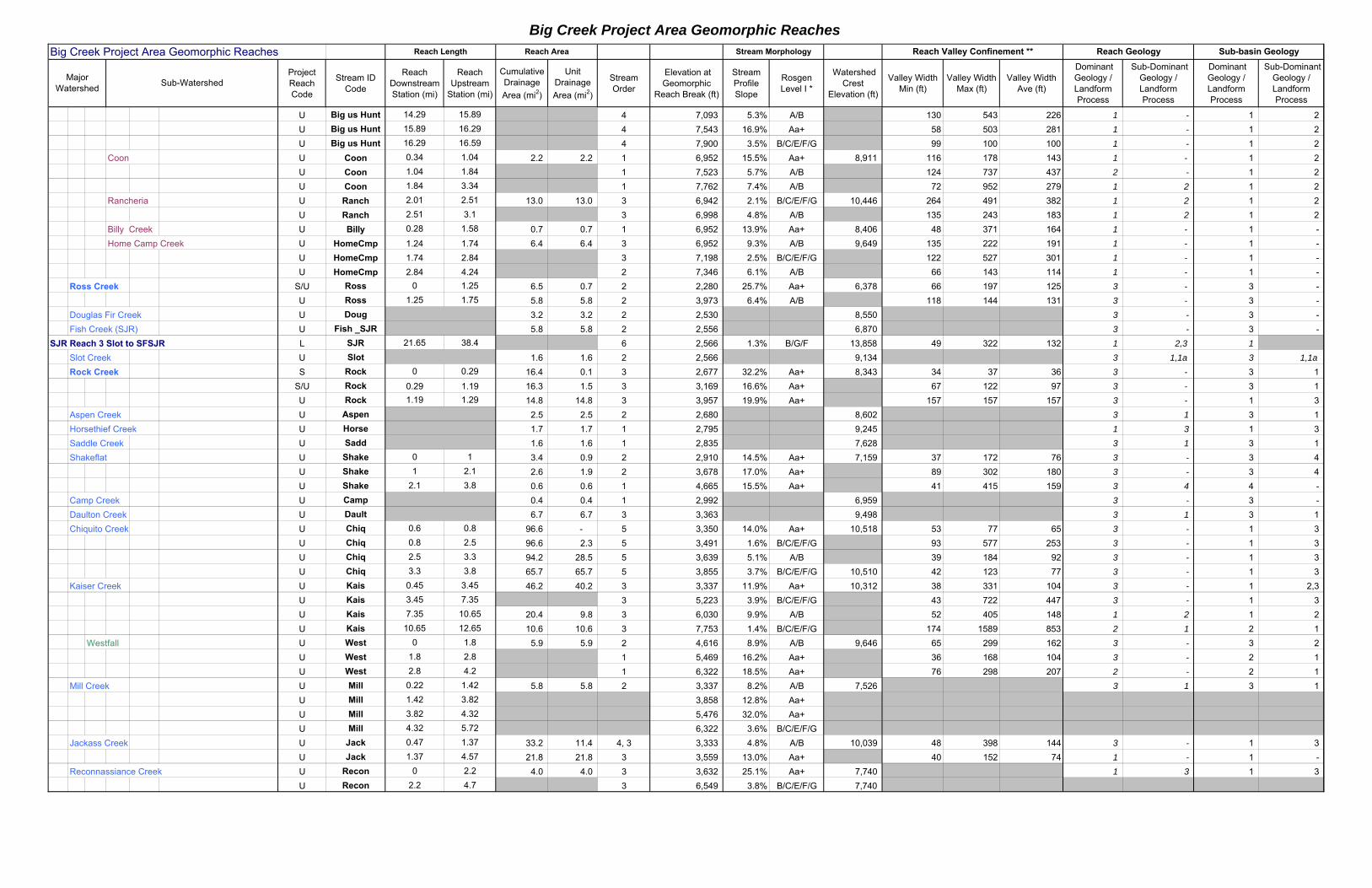
Big Creek Project Area Geomorphic Reaches
Big Creek Project Area Geomorphic Reaches
Project Reach Code
Stream ID Code
Reach Downstream Station (mi)
Reach Upstream
Station (mi)
Cumulative Drainage
Area (mi2)
Unit Drainage
Area (mi2)
Stream Order
Elevation at Geomorphic
Reach Break (ft)
Stream Profile Slope
Rosgen Level I *
Watershed Crest
Elevation (ft)
Valley Width Min (ft)
Valley Width Max (ft)
Valley Width Ave (ft)
Dominant Geology / Landform Process
Sub-Dominant Geology / Landform Process
Dominant Geology / Landform Process
Sub-Dominant Geology / Landform Process
Sub-Watershed
Sub-basin GeologyReach Geology
Major Watershed
Reach Valley Confinement **Reach Length Reach Area Stream Morphology
U Big us Hunt 14.29 15.89 4 7,093 5.3% A/B 130 543 226 1 - 1 2
U Big us Hunt 15.89 16.29 4 7,543 16.9% Aa+ 58 503 281 1 - 1 2
U Big us Hunt 16.29 16.59 4 7,900 3.5% B/C/E/F/G 99 100 100 1 - 1 2
Coon U Coon 0.34 1.04 2.2 2.2 1 6,952 15.5% Aa+ 8,911 116 178 143 1 - 1 2
U Coon 1.04 1.84 1 7,523 5.7% A/B 124 737 437 2 - 1 2
U Coon 1.84 3.34 1 7,762 7.4% A/B 72 952 279 1 2 1 2
Rancheria U Ranch 2.01 2.51 13.0 13.0 3 6,942 2.1% B/C/E/F/G 10,446 264 491 382 1 2 1 2
U Ranch 2.51 3.1 3 6,998 4.8% A/B 135 243 183 1 2 1 2
Billy Creek U Billy 0.28 1.58 0.7 0.7 1 6,952 13.9% Aa+ 8,406 48 371 164 1 - 1 -
Home Camp Creek U HomeCmp 1.24 1.74 6.4 6.4 3 6,952 9.3% A/B 9,649 135 222 191 1 - 1 -
U HomeCmp 1.74 2.84 3 7,198 2.5% B/C/E/F/G 122 527 301 1 - 1 -
U HomeCmp 2.84 4.24 2 7,346 6.1% A/B 66 143 114 1 - 1 -
Ross Creek S/U Ross 0 1.25 6.5 0.7 2 2,280 25.7% Aa+ 6,378 66 197 125 3 - 3 -
U Ross 1.25 1.75 5.8 5.8 2 3,973 6.4% A/B 118 144 131 3 - 3 -
Douglas Fir Creek U Doug 3.2 3.2 2 2,530 8,550 3 - 3 -
Fish Creek (SJR) U Fish _SJR 5.8 5.8 2 2,556 6,870 3 - 3 -
SJR Reach 3 Slot to SFSJR L SJR 21.65 38.4 6 2,566 1.3% B/G/F 13,858 49 322 132 1 2,3 1
Slot Creek U Slot 1.6 1.6 2 2,566 9,134 3 1,1a 3 1,1a
Rock Creek S Rock 0 0.29 16.4 0.1 3 2,677 32.2% Aa+ 8,343 34 37 36 3 - 3 1
S/U Rock 0.29 1.19 16.3 1.5 3 3,169 16.6% Aa+ 67 122 97 3 - 3 1
U Rock 1.19 1.29 14.8 14.8 3 3,957 19.9% Aa+ 157 157 157 3 - 1 3
Aspen Creek U Aspen 2.5 2.5 2 2,680 8,602 3 1 3 1
Horsethief Creek U Horse 1.7 1.7 1 2,795 9,245 1 3 1 3
Saddle Creek U Sadd 1.6 1.6 1 2,835 7,628 3 1 3 1
Shakeflat U Shake 0 1 3.4 0.9 2 2,910 14.5% Aa+ 7,159 37 172 76 3 - 3 4
U Shake 1 2.1 2.6 1.9 2 3,678 17.0% Aa+ 89 302 180 3 - 3 4
U Shake 2.1 3.8 0.6 0.6 1 4,665 15.5% Aa+ 41 415 159 3 4 4 -
Camp Creek U Camp 0.4 0.4 1 2,992 6,959 3 - 3 -
Daulton Creek U Dault 6.7 6.7 3 3,363 9,498 3 1 3 1
Chiquito Creek U Chiq 0.6 0.8 96.6 - 5 3,350 14.0% Aa+ 10,518 53 77 65 3 - 1 3
U Chiq 0.8 2.5 96.6 2.3 5 3,491 1.6% B/C/E/F/G 93 577 253 3 - 1 3
U Chiq 2.5 3.3 94.2 28.5 5 3,639 5.1% A/B 39 184 92 3 - 1 3
U Chiq 3.3 3.8 65.7 65.7 5 3,855 3.7% B/C/E/F/G 10,510 42 123 77 3 - 1 3
Kaiser Creek U Kais 0.45 3.45 46.2 40.2 3 3,337 11.9% Aa+ 10,312 38 331 104 3 - 1 2,3
U Kais 3.45 7.35 3 5,223 3.9% B/C/E/F/G 43 722 447 3 - 1 3
U Kais 7.35 10.65 20.4 9.8 3 6,030 9.9% A/B 52 405 148 1 2 1 2
U Kais 10.65 12.65 10.6 10.6 3 7,753 1.4% B/C/E/F/G 174 1589 853 2 1 2 1
Westfall U West 0 1.8 5.9 5.9 2 4,616 8.9% A/B 9,646 65 299 162 3 - 3 2
U West 1.8 2.8 1 5,469 16.2% Aa+ 36 168 104 3 - 2 1
U West 2.8 4.2 1 6,322 18.5% Aa+ 76 298 207 2 - 2 1
Mill Creek U Mill 0.22 1.42 5.8 5.8 2 3,337 8.2% A/B 7,526 3 1 3 1
U Mill 1.42 3.82 3,858 12.8% Aa+
U Mill 3.82 4.32 5,476 32.0% Aa+
U Mill 4.32 5.72 6,322 3.6% B/C/E/F/G
Jackass Creek U Jack 0.47 1.37 33.2 11.4 4, 3 3,333 4.8% A/B 10,039 48 398 144 3 - 1 3
U Jack 1.37 4.57 21.8 21.8 3 3,559 13.0% Aa+ 40 152 74 1 - 1 -
Reconnassiance Creek U Recon 0 2.2 4.0 4.0 3 3,632 25.1% Aa+ 7,740 1 3 1 3
U Recon 2.2 4.7 3 6,549 3.8% B/C/E/F/G 7,740
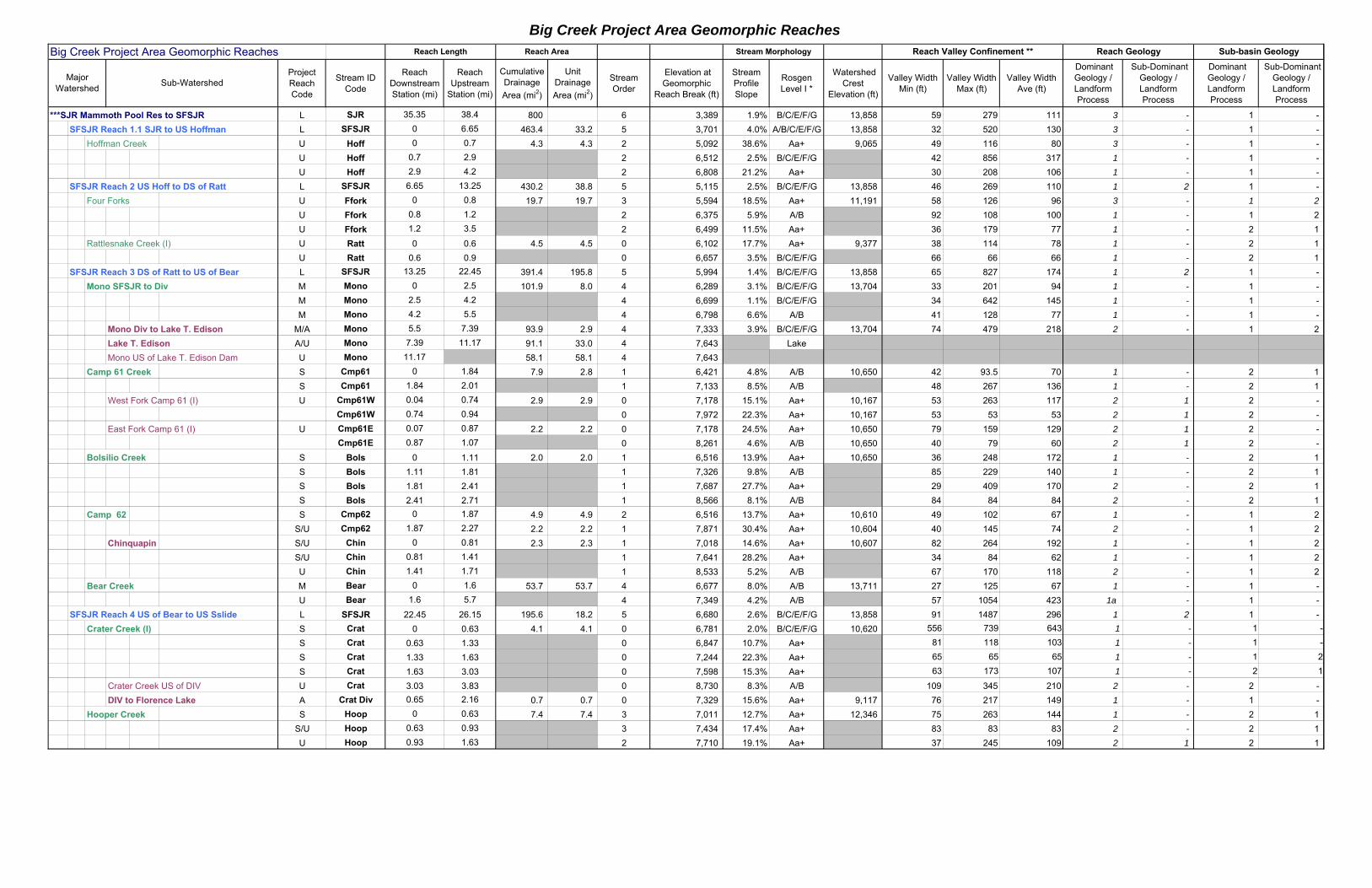
Big Creek Project Area Geomorphic Reaches
Big Creek Project Area Geomorphic Reaches
Project Reach Code
Stream ID Code
Reach Downstream Station (mi)
Reach Upstream
Station (mi)
Cumulative Drainage
Area (mi2)
Unit Drainage
Area (mi2)
Stream Order
Elevation at Geomorphic
Reach Break (ft)
Stream Profile Slope
Rosgen Level I *
Watershed Crest
Elevation (ft)
Valley Width Min (ft)
Valley Width Max (ft)
Valley Width Ave (ft)
Dominant Geology / Landform Process
Sub-Dominant Geology / Landform Process
Dominant Geology / Landform Process
Sub-Dominant Geology / Landform Process
Sub-Watershed
Sub-basin GeologyReach Geology
Major Watershed
Reach Valley Confinement **Reach Length Reach Area Stream Morphology
***SJR Mammoth Pool Res to SFSJR L SJR 35.35 38.4 800 6 3,389 1.9% B/C/E/F/G 13,858 59 279 111 3 - 1 -
SFSJR Reach 1.1 SJR to US Hoffman L SFSJR 0 6.65 463.4 33.2 5 3,701 4.0% A/B/C/E/F/G 13,858 32 520 130 3 - 1 -
Hoffman Creek U Hoff 0 0.7 4.3 4.3 2 5,092 38.6% Aa+ 9,065 49 116 80 3 - 1 -
U Hoff 0.7 2.9 2 6,512 2.5% B/C/E/F/G 42 856 317 1 - 1 -
U Hoff 2.9 4.2 2 6,808 21.2% Aa+ 30 208 106 1 - 1 -
SFSJR Reach 2 US Hoff to DS of Ratt L SFSJR 6.65 13.25 430.2 38.8 5 5,115 2.5% B/C/E/F/G 13,858 46 269 110 1 2 1 -
Four Forks U Ffork 0 0.8 19.7 19.7 3 5,594 18.5% Aa+ 11,191 58 126 96 3 - 1 2
U Ffork 0.8 1.2 2 6,375 5.9% A/B 92 108 100 1 - 1 2
U Ffork 1.2 3.5 2 6,499 11.5% Aa+ 36 179 77 1 - 2 1
Rattlesnake Creek (I) U Ratt 0 0.6 4.5 4.5 0 6,102 17.7% Aa+ 9,377 38 114 78 1 - 2 1
U Ratt 0.6 0.9 0 6,657 3.5% B/C/E/F/G 66 66 66 1 - 2 1
SFSJR Reach 3 DS of Ratt to US of Bear L SFSJR 13.25 22.45 391.4 195.8 5 5,994 1.4% B/C/E/F/G 13,858 65 827 174 1 2 1 -
Mono SFSJR to Div M Mono 0 2.5 101.9 8.0 4 6,289 3.1% B/C/E/F/G 13,704 33 201 94 1 - 1 -
M Mono 2.5 4.2 4 6,699 1.1% B/C/E/F/G 34 642 145 1 - 1 -
M Mono 4.2 5.5 4 6,798 6.6% A/B 41 128 77 1 - 1 -
Mono Div to Lake T. Edison M/A Mono 5.5 7.39 93.9 2.9 4 7,333 3.9% B/C/E/F/G 13,704 74 479 218 2 - 1 2
Lake T. Edison A/U Mono 7.39 11.17 91.1 33.0 4 7,643 Lake
Mono US of Lake T. Edison Dam U Mono 11.17 58.1 58.1 4 7,643
Camp 61 Creek S Cmp61 0 1.84 7.9 2.8 1 6,421 4.8% A/B 10,650 42 93.5 70 1 - 2 1
S Cmp61 1.84 2.01 1 7,133 8.5% A/B 48 267 136 1 - 2 1
West Fork Camp 61 (I) U Cmp61W 0.04 0.74 2.9 2.9 0 7,178 15.1% Aa+ 10,167 53 263 117 2 1 2 -
Cmp61W 0.74 0.94 0 7,972 22.3% Aa+ 10,167 53 53 53 2 1 2 -
East Fork Camp 61 (I) U Cmp61E 0.07 0.87 2.2 2.2 0 7,178 24.5% Aa+ 10,650 79 159 129 2 1 2 -
Cmp61E 0.87 1.07 0 8,261 4.6% A/B 10,650 40 79 60 2 1 2 -
Bolsilio Creek S Bols 0 1.11 2.0 2.0 1 6,516 13.9% Aa+ 10,650 36 248 172 1 - 2 1
S Bols 1.11 1.81 1 7,326 9.8% A/B 85 229 140 1 - 2 1
S Bols 1.81 2.41 1 7,687 27.7% Aa+ 29 409 170 2 - 2 1
S Bols 2.41 2.71 1 8,566 8.1% A/B 84 84 84 2 - 2 1
Camp 62 S Cmp62 0 1.87 4.9 4.9 2 6,516 13.7% Aa+ 10,610 49 102 67 1 - 1 2
S/U Cmp62 1.87 2.27 2.2 2.2 1 7,871 30.4% Aa+ 10,604 40 145 74 2 - 1 2
Chinquapin S/U Chin 0 0.81 2.3 2.3 1 7,018 14.6% Aa+ 10,607 82 264 192 1 - 1 2
S/U Chin 0.81 1.41 1 7,641 28.2% Aa+ 34 84 62 1 - 1 2
U Chin 1.41 1.71 1 8,533 5.2% A/B 67 170 118 2 - 1 2
Bear Creek M Bear 0 1.6 53.7 53.7 4 6,677 8.0% A/B 13,711 27 125 67 1 - 1 -
U Bear 1.6 5.7 4 7,349 4.2% A/B 57 1054 423 1a - 1 -
SFSJR Reach 4 US of Bear to US Sslide L SFSJR 22.45 26.15 195.6 18.2 5 6,680 2.6% B/C/E/F/G 13,858 91 1487 296 1 2 1 -
Crater Creek (I) S Crat 0 0.63 4.1 4.1 0 6,781 2.0% B/C/E/F/G 10,620 556 739 643 1 - 1 -
S Crat 0.63 1.33 0 6,847 10.7% Aa+ 81 118 103 1 - 1 -
S Crat 1.33 1.63 0 7,244 22.3% Aa+ 65 65 65 1 - 1 2
S Crat 1.63 3.03 0 7,598 15.3% Aa+ 63 173 107 1 - 2 1
Crater Creek US of DIV U Crat 3.03 3.83 0 8,730 8.3% A/B 109 345 210 2 - 2 -
DIV to Florence Lake A Crat Div 0.65 2.16 0.7 0.7 0 7,329 15.6% Aa+ 9,117 76 217 149 1 - 1 -
Hooper Creek S Hoop 0 0.63 7.4 7.4 3 7,011 12.7% Aa+ 12,346 75 263 144 1 - 2 1
S/U Hoop 0.63 0.93 3 7,434 17.4% Aa+ 83 83 83 2 - 2 1
U Hoop 0.93 1.63 2 7,710 19.1% Aa+ 37 245 109 2 1 2 1
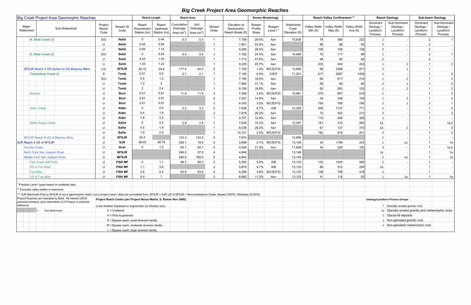
Big Creek Project Area Geomorphic Reaches
Big Creek Project Area Geomorphic Reaches
Project Reach Code
Stream ID Code
Reach Downstream Station (mi)
Reach Upstream
Station (mi)
Cumulative Drainage
Area (mi2)
Unit Drainage
Area (mi2)
Stream Order
Elevation at Geomorphic
Reach Break (ft)
Stream Profile Slope
Rosgen Level I *
Watershed Crest
Elevation (ft)
Valley Width Min (ft)
Valley Width Max (ft)
Valley Width Ave (ft)
Dominant Geology / Landform Process
Sub-Dominant Geology / Landform Process
Dominant Geology / Landform Process
Sub-Dominant Geology / Landform Process
Sub-Watershed
Sub-basin GeologyReach Geology
Major Watershed
Reach Valley Confinement **Reach Length Reach Area Stream Morphology
N. Slide Creek (I) S/U Nslid 0 0.44 0.3 0.3 1 7,159 29.4% Aa+ 10,636 76 389 222 1 - 2 1
U Nslid 0.44 0.94 1 7,841 53.9% Aa+ 88 98 93 2 - 2 -
U Nslid 0.94 1.14 1 9,265 28.6% Aa+ 108 108 108 2 - 2 -
S. Slide Creek (I) S/U Sslid 0 0.43 0.4 0.4 1 7,162 24.3% Aa+ 10,699 70 117 98 1 - 2 1
U Sslid 0.43 1.03 1 7,713 47.8% Aa+ 48 80 64 2 - 2 -
U Sslid 1.03 1.23 1 9,229 45.7% Aa+ 453 453 453 1 2 1 2
SFSJR Reach 5 US Sslide to US Blayney Mdw L/U SFSJR 26.15 34.9 177.4 44.2 5 7,195 1.0% B/C/E/F/G 13,858 69 2388 971 2 1 1 -
Tombstone Creek (I) S Tomb 0.01 0.5 2.1 2.1 1 7,195 0.0% C/E/F 11,201 617 2087 1456 1 - 1 2
S/U Tomb 0.5 1.2 1 7,195 18.6% Aa+ 66 617 214 1 2 1 2
U Tomb 1.2 2 1 7,884 31.1% Aa+ 69 89 80 2 1 1 2
U Tomb 2 2.4 1 9,199 18.8% Aa+ 62 263 132 1 2 1 2
Boulder U Boul 0.01 0.61 11.9 11.9 3 7,346 3.5% B/C/E/F/G 10,981 275 857 618 1 - 1 2
U Boul 0.61 2.81 2 7,457 14.9% Aa+ 54 246 109 1 2 1 2
U Boul 2.81 2.91 2 9,193 3.0% B/C/E/F/G 795 795 795 2 1 2 1
Alder Creek U Alder 0 0.4 2.2 2.2 2 7,638 8.7% A/B 12,329 545 1127 771 1 - 1 2
U Alder 0.4 1.8 2 7,818 26.2% Aa+ 72 422 212 2 - 1 2
U Alder 1.8 2.2 1 9,757 12.9% Aa+ 110 546 328 1 - 1 -
Sallie Keyes Creek U Sallie 0 0.5 2.8 2.8 1 7,638 15.2% Aa+ 12,057 181 310 260 1a - 1 1a,2
U Sallie 0.5 1.9 1 8,038 28.2% Aa+ 67 137 310 1a 2 1 2
U Sallie 1.9 2.2 1 10,121 2.5% B/C/E/F/G 182 219 201 2 - 1 2
SFSJR Reach 6 US of Blayney Mdw U SFSJR 34.9 133.3 133.3 5 7,674 13,858 1 - 1 -
SJR Reach 4 US of SFSJR U SJR 38.45 48.75 329.1 19.0 5 3,698 2.1% B/C/E/F/G 13,146 30 1198 224 1 1a 1 1a
Granite Creek U Gran 0 1.5 64.1 64.1 4 4,026 21.9% Aa+ 11,608 44 226 100 3 - 1 1a,2
North Fork San Joaquin River U NFSJR 246.0 57.0 4 4,846 13,146 1a - 1 1a
Middle Fork San Joaquin River U MFSJR 246.0 189.0 5 4,843 13,143 1 1a 1 1a
Fish Creek (MFSJR) U FISH MF 0 1.1 89.3 89.3 4 5,354 5.6% A/B 13,133 152 1245 560 1 - 1 -
DS of Fox Mdw U FISH MF 1.1 3.6 4 5,679 4.7% A/B 13,133 86 512 206 1a - 1 -
Fox Mdw U FISH MF 3.6 5.4 63.6 63.6 4 6,296 3.8% B/C/E/F/G 13,133 136 708 418 1 - 1 -
US of Fox Mdw U FISH MF 5.4 7 3 6,660 11.2% Aa+ 13,133 41 118 92 1 1a 1 1a
* Possible Level I types based on available data
** Excludes valley widths in reservoirs
*** SJR Mammoth Pool to SFSJR is not a 'geomorphic' reach, but a project reach--data are cumulated from: SFSJR + SJR US of SFSJR + Reconnaissance Creek. [Aspect SW/W; Hillslopes 25-50%]
Project Reach Codes (per Project Nexus Matrix, S. Rowan Nov 2000): Geology/Landform Process Groups
(Lists whether bypassed or augmented, by tributary size) 1 Glacially eroded granitic rock
= Not determined U = Unaltered 1a Glacially eroded granitic and metamorphic rocks
A = 2 Glacial till deposits
S = 3 Non-glaciated granitic rock
M = 4 Non-glaciated metamorphic rock
L =
Bypass reach, small diversion facility
Bypass reach, moderate diversion facility
Bypass reach, large diversion facility
Project Reaches are indicated by Bold. All named USGS perennial streams, plus intermittent (I) if Project or potential reference.
Flow Augmented

Candidate Geomorphic Reference Reaches
Project Reach Code
DS Station (RM)
US Station (RM)
Rosgen Level I Above Diversion?
Other Sub-basin? DS Station
(RM) US Station
(RM)
Stream Profile / Rosgen Level I Stream Type
Drainage Area
Elevation at Geomorphic Reach Break
Maximum Basin
Elevation
Stream Order
Reach Geology
Basin Geology
Basin Aspect
Valley Width
Basin Hillslopes
San Joaquin River to SFSJR ConfluenceSJR BC PH4 to Redinger L 0.00 6.15 B/C/E/F/G N N
SJR Redinger to Dam 6 L 6.15 17.05 B/C/E/F/G N N
SJR Dam 6 to Mammoth Pool Dam L 17.05 26.55 B/C/E/F/G N N
SJR Mammoth Pool Reservoir to SFSJR L 35.35 38.45 B/C/E/F/G Y N 38.45 41.65 + - + + - - + + - +Stevenson Creek DS Shaver M 0.00 0.73 Aa+ N Jose 1.20 1.70 + + + - + + + - + +Stevenson Creek DS Shaver M 0.73 1.33 A/B Y N 9.30 11.50 + - - + + + - + + +Stevenson Creek DS Shaver M 1.33 2.43 Aa+ N Jose 0.06 1.20 + + - - + + + - + +Stevenson Creek DS Shaver M 2.43 4.23 Aa+ Y N 9.30 11.50 + + - + + + - + - +Stevenson Creek DS Shaver M 2.43 4.23 Aa+ N Kaiser 0.45 3.45 + + + - + + - + + -
NF Stevenson Creek A 0.98 1.58 Aa+ N Stev US Shaver 9.30 11.50 + + + + + + + + + +NF Stevenson Creek A 1.58 2.48 A/B/C/E/F/G Y N 3.58 3.78 + + - + + - + + + +NF Stevenson Creek A 2.48 3.58 Aa+ Y N 3.78 4.58 + + + + + + + + + +
Big Creek DS Huntington M 0.00 0.50 Aa+ N Chiquito 0.60 0.80 + + - + + + + + - -Big Creek DS Huntington M 0.50 4.40 A/B N Chiquito 2.50 3.30 + + - + + + + + - -Big Creek DS Huntington M 4.40 6.30 A/B N Kaiser 0.45 3.45 + - + + - + + - + -Big Creek DS Huntington M 6.30 7.80 Aa+ N Granite 0.00 1.50 + + + + + - + + + +Big Creek DS Huntington M 7.80 9.80 B/C/E/F/G Y N 13.09 13.69 + + + + + + + + - +
Ely Creek S 0.00 0.58 Aa+ Y N 0.98 1.38 + + - + + + + + + +Ely Creek S 0.58 0.98 Aa+ Y N 0.98 1.38 + + - + + + + + + +Balsam Creek S 0.00 0.54 Aa+ N Reconnaissance 0.00 2.20 + + + + + - + - * -Balsam Creek S 0.00 0.54 Aa+ N Mill Creek 1.42 3.82 + + + + + + - + * +Balsam Creek A 0.54 0.74 Aa+ N Reconnaissance 0.00 2.20 + + + + + - + - * -Balsam Creek A 0.54 0.74 Aa+ N Mill Creek 1.42 3.82 + + + + + + - + * +Pitman Creek S 0.04 1.37 Aa+ N Kaiser 0.45 3.45 + + - + - + + + + -Pitman Creek S 0.04 1.37 Aa+ N Rock 1.19 1.29 + + + - - + + - + -Pitman Creek S 1.37 1.57 B/C/E/F/G Y N 1.57 2.41 + + + + + + + + + +
Ross Creek S 0.00 0.85 Aa+ Y N 0.85 1.25 + + + + + + + + + +Rock Creek S 0.00 0.39 Aa+ N Jose 1.20 1.70 + + + - + + + - - -Rock Creek S 0.00 0.39 Aa+ N Jackass 1.37 4.57 + + + - + - - + + -
South Fork San Joaquin RiverSFSJR Reach 1 SJR to US Hoffman L 0.00 6.65 A/B/C/E/F/G N SJR US SFSJR 38.45 48.75 + + + + + - + * - *SFSJR Reach 2 US Hoff to DS of Ratt L 6.65 13.25 B/C/E/F/G N SJR US SFSJR 38.45 48.75 + + - + + - + * - *SFSJR Reach 3 DS of Ratt to US of Bear L 13.25 22.45 B/C/E/F/G Y N 30.30 32.60 + - - + + - + + - *SFSJR Reach 3 DS of Ratt to US of Bear L 13.25 22.45 B/C/E/F/G N Fish (MFSJR) 0.00 1.10 - - + + - + + * + *SFSJR Reach 4 US of Bear to US Sslide L 22.45 26.15 B/C/E/F/G Y N 30.30 32.60 + + + + + - + + + +SFSJR Reach 4 US of Bear to US Sslide L 22.45 26.15 B/C/E/F/G N Fish (MFSJR) 3.60 5.40 + - + + - + + * + *SFSJR Reach 5 US Sslide to US Blayney Mdw L 26.15 28.50 B/C/E/F/G Y N 32.60 34.90 + + + + + + + + + +SFSJR Reach 5 US Sslide to US Blayney Mdw L 26.15 28.50 B/C/E/F/G N Fish (MFSJR) 3.60 5.40 + - + + - - + * - *
Mono Creek M 0.00 2.50 B/C/E/F/G N SFSJR 30.30 32.60 + + + + - + + + - *Mono Creek M 2.50 4.20 B/C/E/F/G N SFSJR 30.30 32.60 + + + + - + + + - *Mono Creek M 4.20 5.50 A/B N Fish (MFSJR) 0.00 1.10 + + - + + + + * - *Mono Creek M 5.50 5.80 B/C/E/F/G N Fish (MFSJR) 3.60 5.40 + + + + + - + + - *Camp 61 Creek S 0.00 1.84 A/B N Kaiser 7.35 10.65 + - + + - + - + + -Bolsilio Creek S 0.00 1.11 Aa+ N Coon 0.34 1.04 + + + - + + - + + -Bolsilio Creek S 1.11 1.81 A/B N Coon 1.84 3.34 + + + - + + + + - -Camp 62 Creek S 0.00 1.37 Aa+ N Rattlesnake 0.60 0.90 - + + + + + - + + -
Chinquapin S 0.00 0.81 Aa+ N Camp 62 1.37 1.87 + + + + + - + + - +
Comparison of Geomorphic Stream Reach and Watershed Characteristics
Project Affected Stream ReachMajor
Watershed
Candidate Reference ReachBig Creek Project Reach
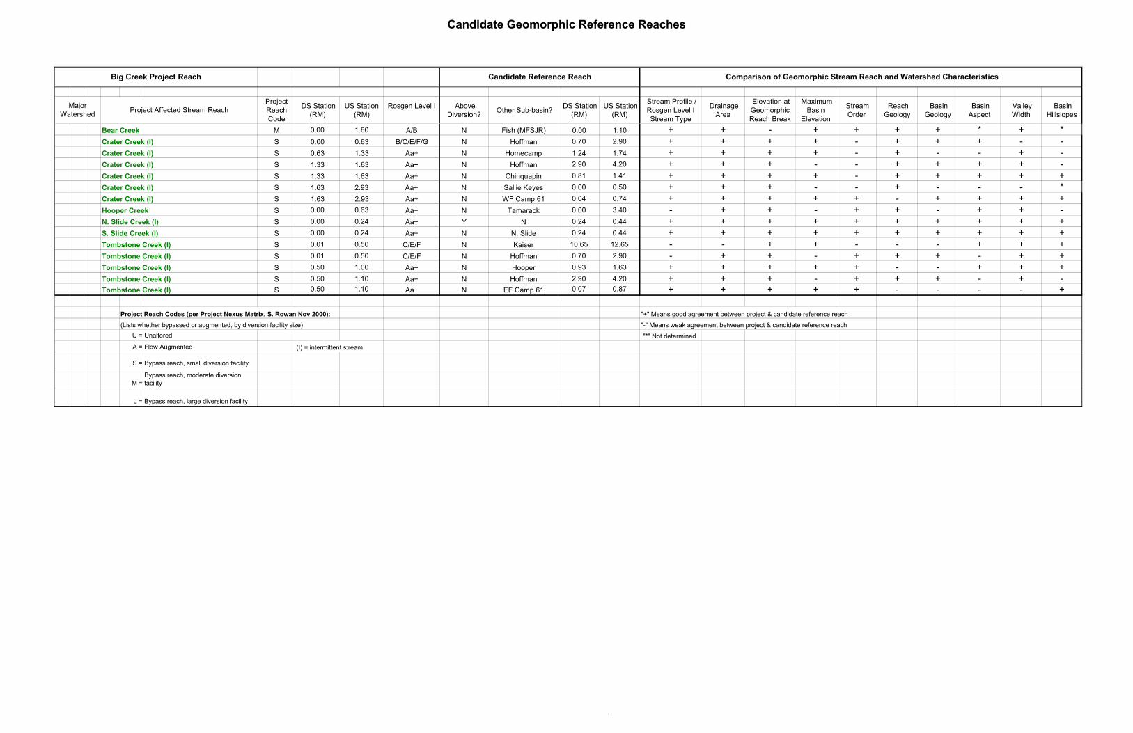
Candidate Geomorphic Reference Reaches
Project Reach Code
DS Station (RM)
US Station (RM)
Rosgen Level I Above Diversion?
Other Sub-basin? DS Station
(RM) US Station
(RM)
Stream Profile / Rosgen Level I Stream Type
Drainage Area
Elevation at Geomorphic Reach Break
Maximum Basin
Elevation
Stream Order
Reach Geology
Basin Geology
Basin Aspect
Valley Width
Basin Hillslopes
Comparison of Geomorphic Stream Reach and Watershed Characteristics
Project Affected Stream ReachMajor
Watershed
Candidate Reference ReachBig Creek Project Reach
Bear Creek M 0.00 1.60 A/B N Fish (MFSJR) 0.00 1.10 + + - + + + + * + *Crater Creek (I) S 0.00 0.63 B/C/E/F/G N Hoffman 0.70 2.90 + + + + - + + + - -Crater Creek (I) S 0.63 1.33 Aa+ N Homecamp 1.24 1.74 + + + + - + - - + -Crater Creek (I) S 1.33 1.63 Aa+ N Hoffman 2.90 4.20 + + + - - + + + + -Crater Creek (I) S 1.33 1.63 Aa+ N Chinquapin 0.81 1.41 + + + + - + + + + +Crater Creek (I) S 1.63 2.93 Aa+ N Sallie Keyes 0.00 0.50 + + + - - + - - - *Crater Creek (I) S 1.63 2.93 Aa+ N WF Camp 61 0.04 0.74 + + + + + - + + + +Hooper Creek S 0.00 0.63 Aa+ N Tamarack 0.00 3.40 - + + - + + - + + -N. Slide Creek (I) S 0.00 0.24 Aa+ Y N 0.24 0.44 + + + + + + + + + +S. Slide Creek (I) S 0.00 0.24 Aa+ N N. Slide 0.24 0.44 + + + + + + + + + +Tombstone Creek (I) S 0.01 0.50 C/E/F N Kaiser 10.65 12.65 - - + + - - - + + +Tombstone Creek (I) S 0.01 0.50 C/E/F N Hoffman 0.70 2.90 - + + - + + + - + +Tombstone Creek (I) S 0.50 1.00 Aa+ N Hooper 0.93 1.63 + + + + + - - + + +Tombstone Creek (I) S 0.50 1.10 Aa+ N Hoffman 2.90 4.20 + + + - + + + - + -Tombstone Creek (I) S 0.50 1.10 Aa+ N EF Camp 61 0.07 0.87 + + + + + - - - - +
Project Reach Codes (per Project Nexus Matrix, S. Rowan Nov 2000): "+" Means good agreement between project & candidate reference reach
(Lists whether bypassed or augmented, by diversion facility size) "-" Means weak agreement between project & candidate reference reach
U = Unaltered "*" Not determined
A = Flow Augmented (I) = intermittent stream
S = Bypass reach, small diversion facility
M = Bypass reach, moderate diversion facility
L = Bypass reach, large diversion facility

Placeholder for Stream Reach Map
Non-Internet Public Information
This Figure has been removed in accordance with the Commission regulationsat 18 CFR Section 388.112.This Figure is considered Non-Internet Public information and should not beposted on the Internet. This information is provided in Volume 4 of the Applicationfor New License and is identified as “Non-Internet Public” information. Thisinformation may be accessed from the FERC’s Public Reference Room, but is notexpected to be posted on the Commission’s electronic library, except as anindexed item.

APPENDIX C
Aerial Reconnaissance Field Survey Data Form andRatings/Guidelines
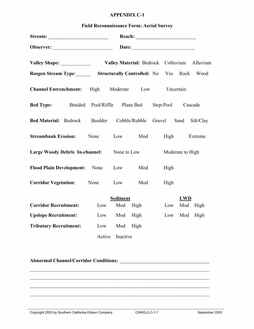
APPENDIX C-1
Field Reconnaissance Form: Aerial Survey
Copyright 2003 by Southern California Edison Company CAWG-2-C-1-1 September 2003
Stream: ________________________ Reach: ________________________
Observer: ________________________ Date: _________________________
Valley Shape: ____________ Valley Material: Bedrock Colluvium Alluvium
Rosgen Stream Type:______ Structurally Controlled: No Yes Rock Wood
Channel Entrenchment: High Moderate Low Uncertain
Bed Type: Braided Pool/Riffle Plane Bed Step-Pool Cascade
Bed Material: Bedrock Boulder Cobble/Rubble Gravel Sand Silt/Clay
Streambank Erosion: None Low Mod High Extreme
Large Woody Debris In-channel: None to Low Moderate to High
Flood Plain Development: None Low Mod High
Corridor Vegetation: None Low Mod High
Sediment LWDCorridor Recruitment: Low Mod High Low Mod High
Upslope Recruitment: Low Mod High Low Mod High
Tributary Recruitment: Low Mod High
Active Inactive
Abnormal Channel/Corridor Conditions: ____________________________________
________________________________________________________________________
________________________________________________________________________
________________________________________________________________________
________________________________________________________________________

APPENDIX C-1
Field Reconnaissance Form: Aerial Survey
Copyright 2003 by Southern California Edison Company CAWG-2-C-1-2 September 2003
Stream: ________________________ Reach: ________________________
Observer: ________________________ Date: _________________________
LWD Jam GPS:____________________________________________________________
Comment:_______________________________________________________
Spoil Site GPS:____________________________________________________________
Comment:_______________________________________________________
Excess SedimentDeposition GPS:____________________________________________________________
Comment:_______________________________________________________
Possible Project Effects:_____________________________________________________________________________
_____________________________________________________________________________
_____________________________________________________________________________
_____________________________________________________________________________
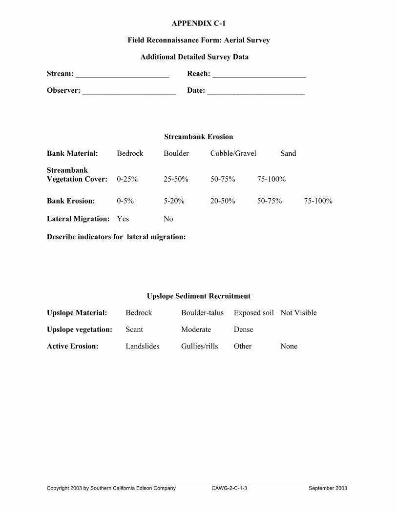
APPENDIX C-1
Field Reconnaissance Form: Aerial Survey
Copyright 2003 by Southern California Edison Company CAWG-2-C-1-3 September 2003
Additional Detailed Survey Data
Stream: ________________________ Reach: ________________________
Observer: ________________________ Date: _________________________
Streambank Erosion
Bank Material: Bedrock Boulder Cobble/Gravel Sand
StreambankVegetation Cover: 0-25% 25-50% 50-75% 75-100%
Bank Erosion: 0-5% 5-20% 20-50% 50-75% 75-100%
Lateral Migration: Yes No
Describe indicators for lateral migration:
Upslope Sediment Recruitment
Upslope Material: Bedrock Boulder-talus Exposed soil Not Visible
Upslope vegetation: Scant Moderate Dense
Active Erosion: Landslides Gullies/rills Other None
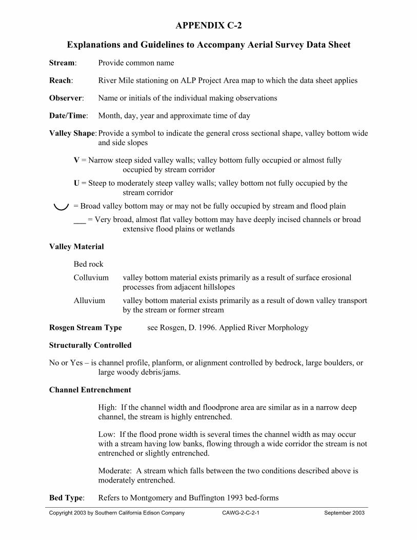
APPENDIX C-2
Explanations and Guidelines to Accompany Aerial Survey Data Sheet
Copyright 2003 by Southern California Edison Company CAWG-2-C-2-1 September 2003
Stream: Provide common name
Reach: River Mile stationing on ALP Project Area map to which the data sheet applies
Observer: Name or initials of the individual making observations
Date/Time: Month, day, year and approximate time of day
Valley Shape: Provide a symbol to indicate the general cross sectional shape, valley bottom wideand side slopes
V = Narrow steep sided valley walls; valley bottom fully occupied or almost fullyoccupied by stream corridor
U = Steep to moderately steep valley walls; valley bottom not fully occupied by thestream corridor
= Broad valley bottom may or may not be fully occupied by stream and flood plain
___ = Very broad, almost flat valley bottom may have deeply incised channels or broadextensive flood plains or wetlands
Valley Material
Bed rock
Colluvium valley bottom material exists primarily as a result of surface erosionalprocesses from adjacent hillslopes
Alluvium valley bottom material exists primarily as a result of down valley transportby the stream or former stream
Rosgen Stream Type see Rosgen, D. 1996. Applied River Morphology
Structurally Controlled
No or Yes – is channel profile, planform, or alignment controlled by bedrock, large boulders, orlarge woody debris/jams.
Channel Entrenchment
High: If the channel width and floodprone area are similar as in a narrow deepchannel, the stream is highly entrenched.
Low: If the flood prone width is several times the channel width as may occurwith a stream having low banks, flowing through a wide corridor the stream is notentrenched or slightly entrenched.
Moderate: A stream which falls between the two conditions described above ismoderately entrenched.
Bed Type: Refers to Montgomery and Buffington 1993 bed-forms
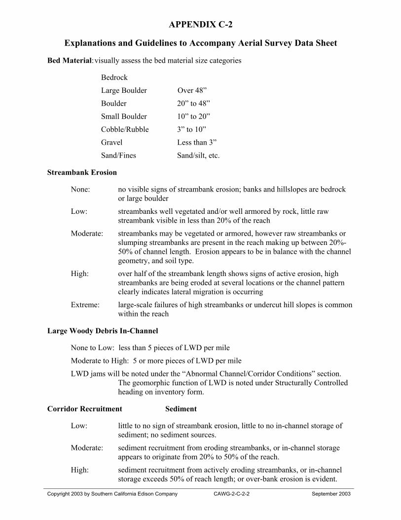
APPENDIX C-2
Explanations and Guidelines to Accompany Aerial Survey Data Sheet
Copyright 2003 by Southern California Edison Company CAWG-2-C-2-2 September 2003
Bed Material:visually assess the bed material size categories
Bedrock
Large Boulder Over 48”
Boulder 20” to 48”
Small Boulder 10” to 20”
Cobble/Rubble 3” to 10”
Gravel Less than 3”
Sand/Fines Sand/silt, etc.
Streambank Erosion
None: no visible signs of streambank erosion; banks and hillslopes are bedrockor large boulder
Low: streambanks well vegetated and/or well armored by rock, little rawstreambank visible in less than 20% of the reach
Moderate: streambanks may be vegetated or armored, however raw streambanks orslumping streambanks are present in the reach making up between 20%-50% of channel length. Erosion appears to be in balance with the channelgeometry, and soil type.
High: over half of the streambank length shows signs of active erosion, highstreambanks are being eroded at several locations or the channel patternclearly indicates lateral migration is occurring
Extreme: large-scale failures of high streambanks or undercut hill slopes is commonwithin the reach
Large Woody Debris In-Channel
None to Low: less than 5 pieces of LWD per mile
Moderate to High: 5 or more pieces of LWD per mile
LWD jams will be noted under the “Abnormal Channel/Corridor Conditions” section.The geomorphic function of LWD is noted under Structurally Controlledheading on inventory form.
Corridor Recruitment Sediment
Low: little to no sign of streambank erosion, little to no in-channel storage ofsediment; no sediment sources.
Moderate: sediment recruitment from eroding streambanks, or in-channel storageappears to originate from 20% to 50% of the reach.
High: sediment recruitment from actively eroding streambanks, or in-channelstorage exceeds 50% of reach length; or over-bank erosion is evident.
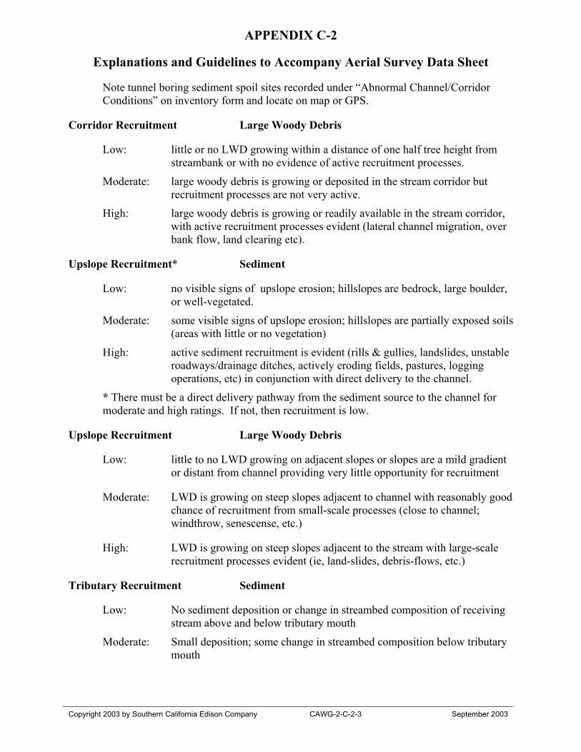
APPENDIX C-2
Explanations and Guidelines to Accompany Aerial Survey Data Sheet
Copyright 2003 by Southern California Edison Company CAWG-2-C-2-3 September 2003
Note tunnel boring sediment spoil sites recorded under “Abnormal Channel/CorridorConditions” on inventory form and locate on map or GPS.
Corridor Recruitment Large Woody Debris
Low: little or no LWD growing within a distance of one half tree height fromstreambank or with no evidence of active recruitment processes.
Moderate: large woody debris is growing or deposited in the stream corridor butrecruitment processes are not very active.
High: large woody debris is growing or readily available in the stream corridor,with active recruitment processes evident (lateral channel migration, overbank flow, land clearing etc).
Upslope Recruitment* Sediment
Low: no visible signs of upslope erosion; hillslopes are bedrock, large boulder,or well-vegetated.
Moderate: some visible signs of upslope erosion; hillslopes are partially exposed soils(areas with little or no vegetation)
High: active sediment recruitment is evident (rills & gullies, landslides, unstableroadways/drainage ditches, actively eroding fields, pastures, loggingoperations, etc) in conjunction with direct delivery to the channel.
* There must be a direct delivery pathway from the sediment source to the channel formoderate and high ratings. If not, then recruitment is low.
Upslope Recruitment Large Woody Debris
Low: little to no LWD growing on adjacent slopes or slopes are a mild gradientor distant from channel providing very little opportunity for recruitment
Moderate: LWD is growing on steep slopes adjacent to channel with reasonably goodchance of recruitment from small-scale processes (close to channel;windthrow, senescense, etc.)
High: LWD is growing on steep slopes adjacent to the stream with large-scalerecruitment processes evident (ie, land-slides, debris-flows, etc.)
Tributary Recruitment Sediment
Low: No sediment deposition or change in streambed composition of receivingstream above and below tributary mouth
Moderate: Small deposition; some change in streambed composition below tributarymouth
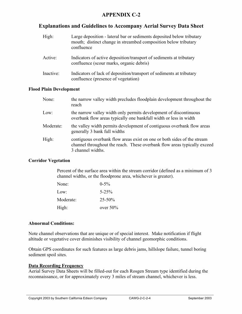
APPENDIX C-2
Explanations and Guidelines to Accompany Aerial Survey Data Sheet
Copyright 2003 by Southern California Edison Company CAWG-2-C-2-4 September 2003
High: Large deposition - lateral bar or sediments deposited below tributarymouth; distinct change in streambed composition below tributaryconfluence
Active: Indicators of active deposition/transport of sediments at tributaryconfluence (scour marks, organic debris)
Inactive: Indicators of lack of deposition/transport of sediments at tributaryconfluence (presence of vegetation)
Flood Plain Development
None: the narrow valley width precludes floodplain development throughout thereach
Low: the narrow valley width only permits development of discontinuousoverbank flow areas typically one bankfull width or less in width
Moderate: the valley width permits development of contiguous overbank flow areasgenerally 3 bank full widths
High: contiguous overbank flow areas exist on one or both sides of the streamchannel throughout the reach. These overbank flow areas typically exceed3 channel widths.
Corridor Vegetation
Percent of the surface area within the stream corridor (defined as a minimum of 3channel widths, or the floodprone area, whichever is greater).
None: 0-5%
Low: 5-25%
Moderate: 25-50%
High: over 50%
Abnormal Conditions:
Note channel observations that are unique or of special interest. Make notification if flightaltitude or vegetative cover diminishes visibility of channel geomorphic conditions.
Obtain GPS coordinates for such features as large debris jams, hillslope failure, tunnel boringsediment spoil sites.
Data Recording FrequencyAerial Survey Data Sheets will be filled-out for each Rosgen Stream type identified during thereconnaissance, or for approximately every 3 miles of stream channel, whichever is less.
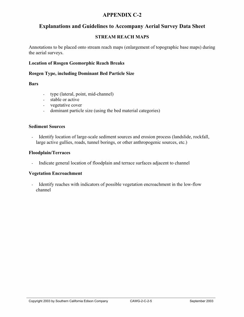
APPENDIX C-2
Explanations and Guidelines to Accompany Aerial Survey Data Sheet
Copyright 2003 by Southern California Edison Company CAWG-2-C-2-5 September 2003
STREAM REACH MAPS
Annotations to be placed onto stream reach maps (enlargement of topographic base maps) duringthe aerial surveys.
Location of Rosgen Geomorphic Reach Breaks
Rosgen Type, including Dominant Bed Particle Size
Bars
- type (lateral, point, mid-channel)- stable or active- vegetative cover- dominant particle size (using the bed material categories)
Sediment Sources
- Identify location of large-scale sediment sources and erosion process (landslide, rockfall,large active gullies, roads, tunnel borings, or other anthropogenic sources, etc.)
Floodplain/Terraces
- Indicate general location of floodplain and terrace surfaces adjacent to channel
Vegetation Encroachment
- Identify reaches with indicators of possible vegetation encroachment in the low-flowchannel

APPENDIX D
Ground Survey Reconnaissance Field Survey Data Form

CAWG-2 - Appendix DFIELD RECONNAISSANCE DATA FOR GROUND SURVEYS
Survey Crew:
Sheet_____ of ______
GPS Log
Date Data Log ID # Stream Station GPS N GPS W Feature
GPS coordinates recorded in UTM WGS 84
Copyright 2003 by Southern California Edison Company September 2003
APPENDIX E
Completed Field Survey Data FormsGROUND Completed Field Survey Data FormsAERIAL Completed Field Survey Data Forms
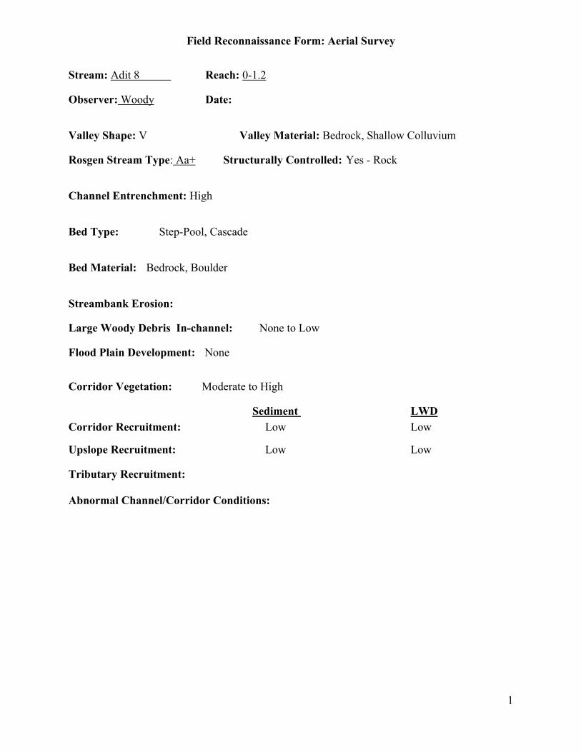
Field Reconnaissance Form: Aerial Survey
1
Stream: Adit 8 Reach: 0-1.2
Observer: Woody Date:
Valley Shape: V Valley Material: Bedrock, Shallow Colluvium
Rosgen Stream Type: Aa+ Structurally Controlled: Yes - Rock
Channel Entrenchment: High
Bed Type: Step-Pool, Cascade
Bed Material: Bedrock, Boulder
Streambank Erosion:
Large Woody Debris In-channel: None to Low
Flood Plain Development: None
Corridor Vegetation: Moderate to High
Sediment LWDCorridor Recruitment: Low Low
Upslope Recruitment: Low Low
Tributary Recruitment:
Abnormal Channel/Corridor Conditions:
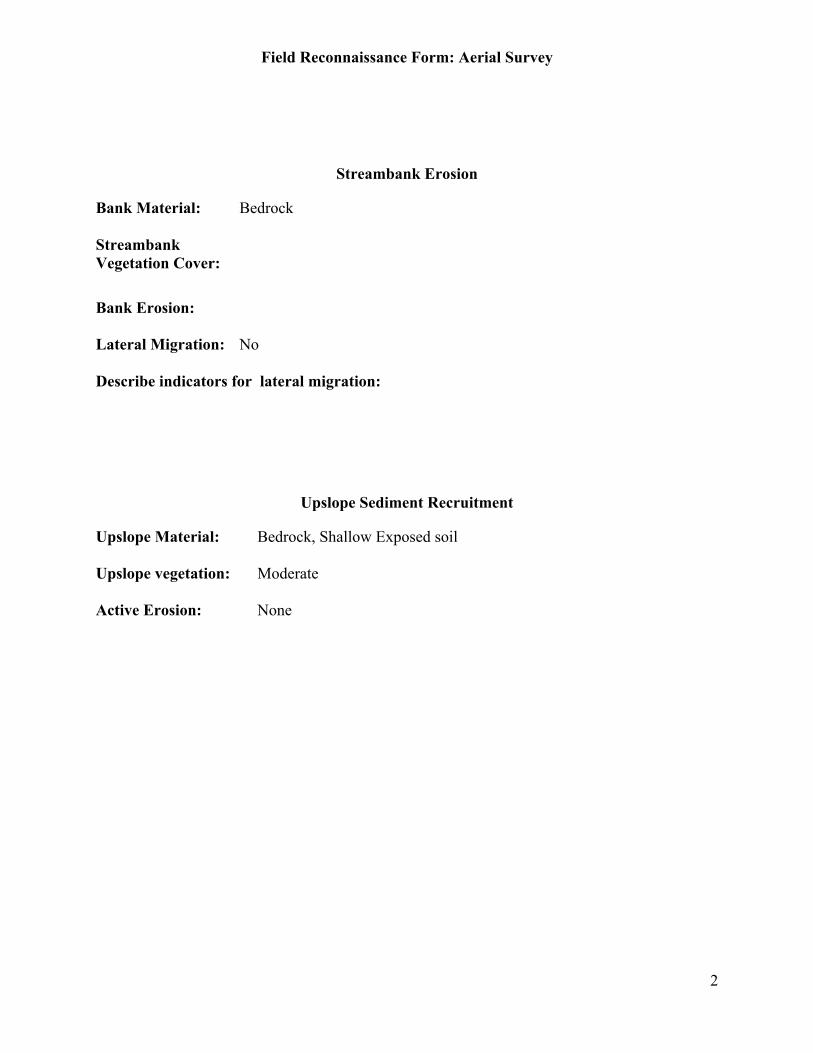
Field Reconnaissance Form: Aerial Survey
2
Streambank Erosion
Bank Material: Bedrock
StreambankVegetation Cover:
Bank Erosion:
Lateral Migration: No
Describe indicators for lateral migration:
Upslope Sediment Recruitment
Upslope Material: Bedrock, Shallow Exposed soil
Upslope vegetation: Moderate
Active Erosion: None
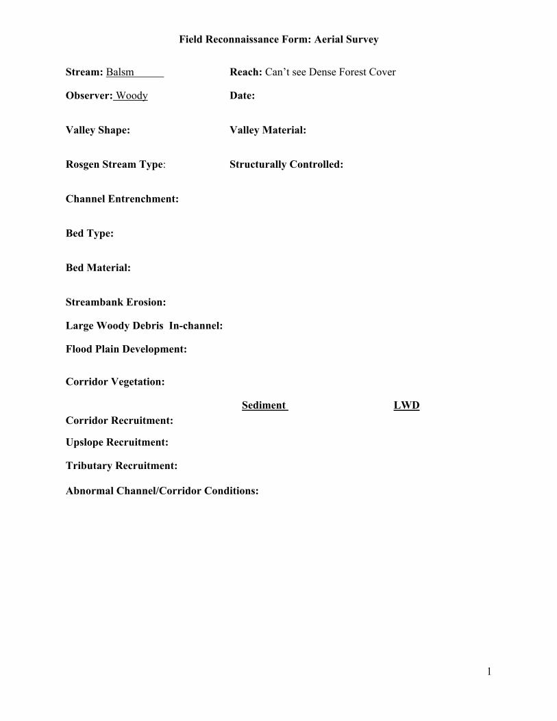
Field Reconnaissance Form: Aerial Survey
1
Stream: Balsm Reach: Can’t see Dense Forest Cover
Observer: Woody Date:
Valley Shape: Valley Material:
Rosgen Stream Type: Structurally Controlled:
Channel Entrenchment:
Bed Type:
Bed Material:
Streambank Erosion:
Large Woody Debris In-channel:
Flood Plain Development:
Corridor Vegetation:
Sediment LWDCorridor Recruitment:
Upslope Recruitment:
Tributary Recruitment:
Abnormal Channel/Corridor Conditions:
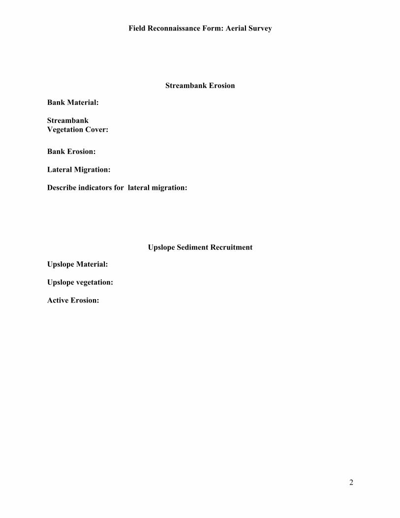
Field Reconnaissance Form: Aerial Survey
2
Streambank Erosion
Bank Material:
StreambankVegetation Cover:
Bank Erosion:
Lateral Migration:
Describe indicators for lateral migration:
Upslope Sediment Recruitment
Upslope Material:
Upslope vegetation:
Active Erosion:
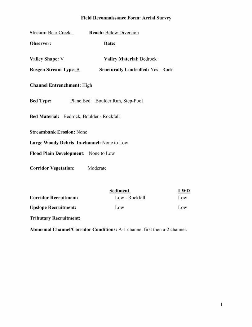
Field Reconnaissance Form: Aerial Survey
1
Stream: Bear Creek Reach: Below Diversion
Observer: Date:
Valley Shape: V Valley Material: Bedrock
Rosgen Stream Type: B Sructurally Controlled: Yes - Rock
Channel Entrenchment: High
Bed Type: Plane Bed – Boulder Run, Step-Pool
Bed Material: Bedrock, Boulder - Rockfall
Streambank Erosion: None
Large Woody Debris In-channel: None to Low
Flood Plain Development: None to Low
Corridor Vegetation: Moderate
Sediment LWDCorridor Recruitment: Low - Rockfall Low
Upslope Recruitment: Low Low
Tributary Recruitment:
Abnormal Channel/Corridor Conditions: A-1 channel first then a-2 channel.
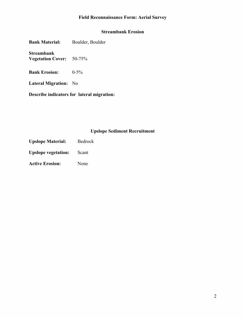
Field Reconnaissance Form: Aerial Survey
2
Streambank Erosion
Bank Material: Boulder, Boulder
StreambankVegetation Cover: 50-75%
Bank Erosion: 0-5%
Lateral Migration: No
Describe indicators for lateral migration:
Upslope Sediment Recruitment
Upslope Material: Bedrock
Upslope vegetation: Scant
Active Erosion: None
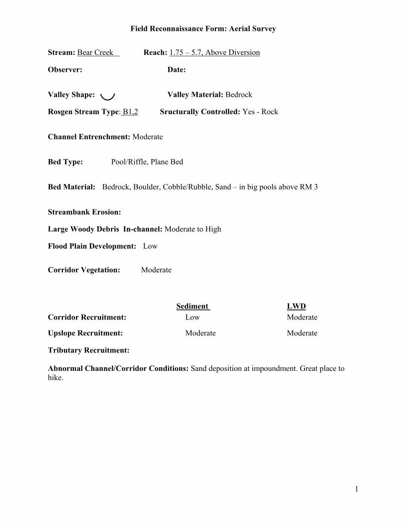
Field Reconnaissance Form: Aerial Survey
1
Stream: Bear Creek Reach: 1.75 – 5.7, Above Diversion
Observer: Date:
Valley Shape: Valley Material: Bedrock
Rosgen Stream Type: B1,2 Sructurally Controlled: Yes - Rock
Channel Entrenchment: Moderate
Bed Type: Pool/Riffle, Plane Bed
Bed Material: Bedrock, Boulder, Cobble/Rubble, Sand – in big pools above RM 3
Streambank Erosion:
Large Woody Debris In-channel: Moderate to High
Flood Plain Development: Low
Corridor Vegetation: Moderate
Sediment LWDCorridor Recruitment: Low Moderate
Upslope Recruitment: Moderate Moderate
Tributary Recruitment:
Abnormal Channel/Corridor Conditions: Sand deposition at impoundment. Great place tohike.

Field Reconnaissance Form: Aerial Survey
2
Streambank Erosion
Bank Material: Boulder, Boulder
StreambankVegetation Cover: 25-50%
Bank Erosion: 0-5%
Lateral Migration: No
Describe indicators for lateral migration:
Upslope Sediment Recruitment
Upslope Material: Bedrock
Upslope vegetation: Moderate
Active Erosion: None
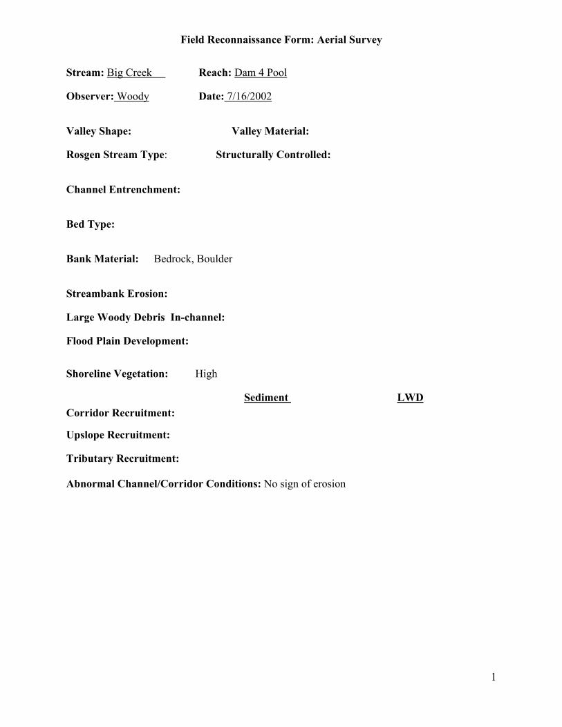
Field Reconnaissance Form: Aerial Survey
1
Stream: Big Creek Reach: Dam 4 Pool
Observer: Woody Date: 7/16/2002
Valley Shape: Valley Material:
Rosgen Stream Type: Structurally Controlled:
Channel Entrenchment:
Bed Type:
Bank Material: Bedrock, Boulder
Streambank Erosion:
Large Woody Debris In-channel:
Flood Plain Development:
Shoreline Vegetation: High
Sediment LWDCorridor Recruitment:
Upslope Recruitment:
Tributary Recruitment:
Abnormal Channel/Corridor Conditions: No sign of erosion
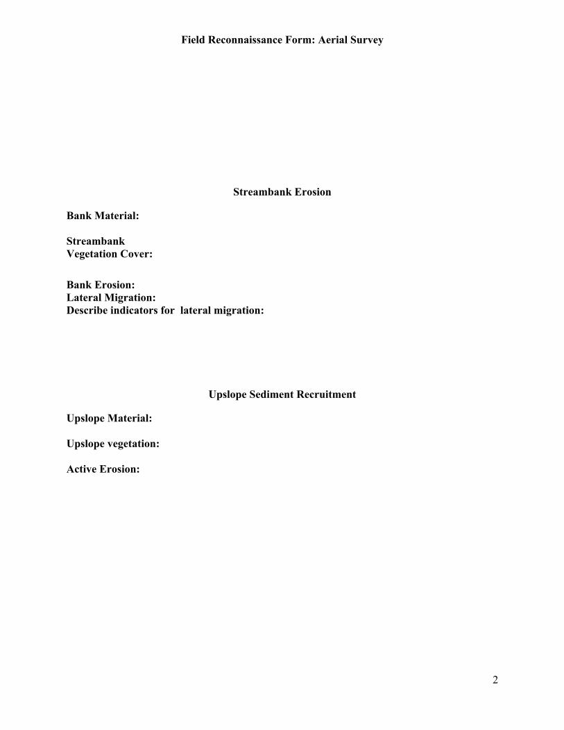
Field Reconnaissance Form: Aerial Survey
2
Streambank Erosion
Bank Material:
StreambankVegetation Cover:
Bank Erosion:Lateral Migration:Describe indicators for lateral migration:
Upslope Sediment Recruitment
Upslope Material:
Upslope vegetation:
Active Erosion:
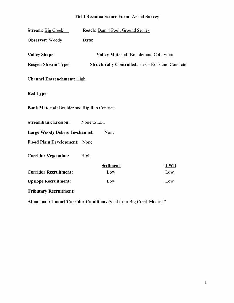
Field Reconnaissance Form: Aerial Survey
1
Stream: Big Creek Reach: Dam 4 Pool, Ground Servey
Observer: Woody Date:
Valley Shape: Valley Material: Boulder and Colluvium
Rosgen Stream Type: Structurally Controlled: Yes – Rock and Concrete
Channel Entrenchment: High
Bed Type:
Bank Material: Boulder and Rip Rap Concrete
Streambank Erosion: None to Low
Large Woody Debris In-channel: None
Flood Plain Development: None
Corridor Vegetation: High
Sediment LWDCorridor Recruitment: Low Low
Upslope Recruitment: Low Low
Tributary Recruitment:
Abnormal Channel/Corridor Conditions:Sand from Big Creek Modest ?

Field Reconnaissance Form: Aerial Survey
2
Streambank Erosion
Bank Material: Boulder and Rip Rap
StreambankVegetation Cover: 50-75%
Bank Erosion: 5-20%
Lateral Migration: No
Describe indicators for lateral migration:
Upslope Sediment Recruitment
Upslope Material: Forest SoilUpslope vegetation: DenseActive Erosion: None
Few foot paths
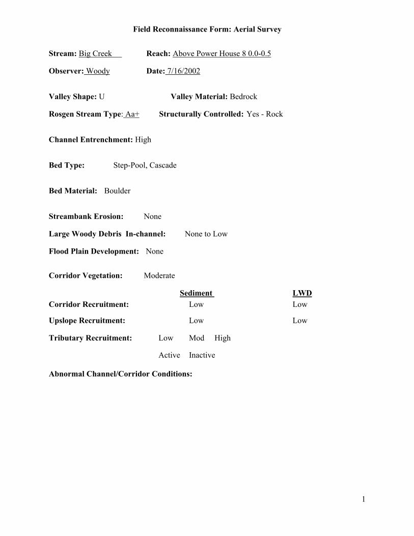
Field Reconnaissance Form: Aerial Survey
1
Stream: Big Creek Reach: Above Power House 8 0.0-0.5
Observer: Woody Date: 7/16/2002
Valley Shape: U Valley Material: Bedrock
Rosgen Stream Type: Aa+ Structurally Controlled: Yes - Rock
Channel Entrenchment: High
Bed Type: Step-Pool, Cascade
Bed Material: Boulder
Streambank Erosion: None
Large Woody Debris In-channel: None to Low
Flood Plain Development: None
Corridor Vegetation: Moderate
Sediment LWDCorridor Recruitment: Low Low
Upslope Recruitment: Low Low
Tributary Recruitment: Low Mod High
Active Inactive
Abnormal Channel/Corridor Conditions:

Field Reconnaissance Form: Aerial Survey
2
Streambank Erosion
Bank Material: Bedrock
StreambankVegetation Cover: 0-25%
Bank Erosion: 0-5%
Lateral Migration: No
Describe indicators for lateral migration:
Upslope Sediment Recruitment
Upslope Material: Bedrock, Shallow SoilUpslope vegetation: ModerateActive Erosion: None
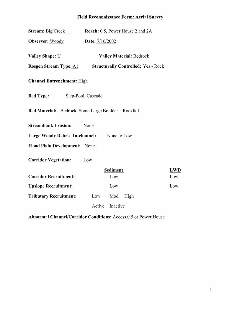
Field Reconnaissance Form: Aerial Survey
1
Stream: Big Creek Reach: 0.5, Power House 2 and 2A
Observer: Woody Date: 7/16/2002
Valley Shape: U Valley Material: Bedrock
Rosgen Stream Type: A1 Structurally Controlled: Yes - Rock
Channel Entrenchment: High
Bed Type: Step-Pool, Cascade
Bed Material: Bedrock, Some Large Boulder – Rockfall
Streambank Erosion: None
Large Woody Debris In-channel: None to Low
Flood Plain Development: None
Corridor Vegetation: Low
Sediment LWDCorridor Recruitment: Low Low
Upslope Recruitment: Low Low
Tributary Recruitment: Low Mod High
Active Inactive
Abnormal Channel/Corridor Conditions: Access 0.5 or Power House

Field Reconnaissance Form: Aerial Survey
2
Streambank Erosion
Bank Material: Bedrock
StreambankVegetation Cover: 0-25%
Bank Erosion: 0-5%
Lateral Migration: No
Describe indicators for lateral migration:
Upslope Sediment Recruitment
Upslope Material: Bedrock, Shallow Soil
Upslope vegetation: Moderate to Dense
Active Erosion: None

Field Reconnaissance Form: Aerial Survey
1
Stream: Big Creek Reach: Above 2 and 2A to Dam 4, 2.1 – 6.1
Observer: Woody Date: 7/16/2002
Valley Shape: V Valley Material: Bedrock, Shallow Colluvium
Rosgen Stream Type: A1 Structurally Controlled: Yes - Rock
Channel Entrenchment: High
Bed Type: Plane Bed, Step-Pool
Bed Material: Bedrock, Boulder – Rockfall
Streambank Erosion: None
Large Woody Debris In-channel: None to Low
Flood Plain Development: None
Corridor Vegetation: Moderate to High
Sediment LWDCorridor Recruitment: Low Low
Upslope Recruitment: Low Low
Tributary Recruitment: Low
Inactive Adit 8 and Ely
Abnormal Channel/Corridor Conditions: Very Small Deposit mouth Balsm, young Willows
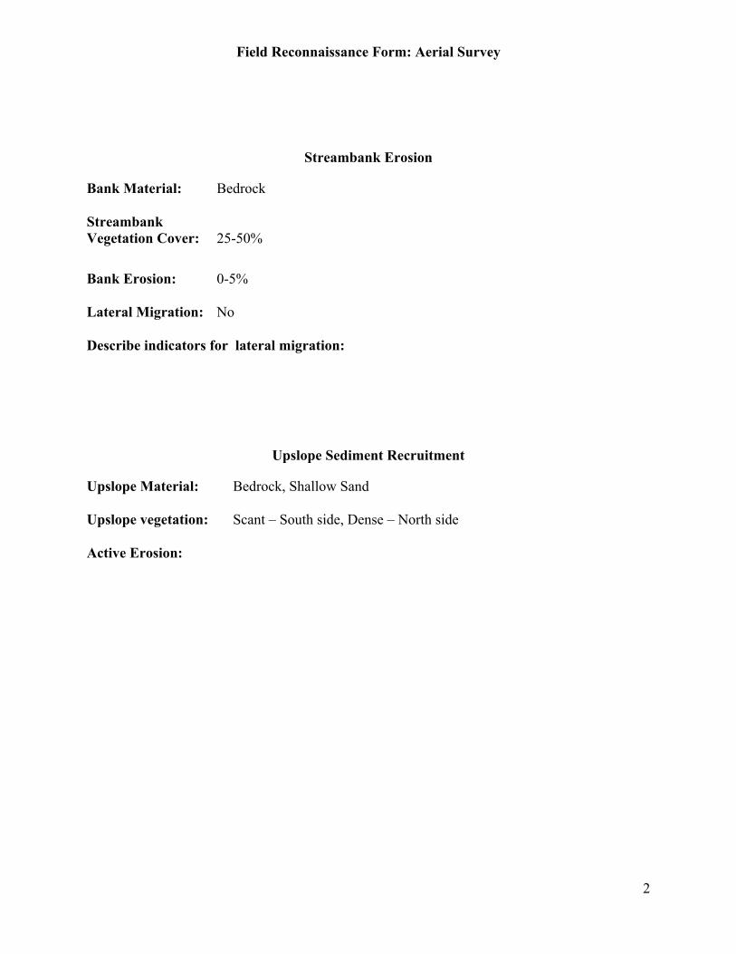
Field Reconnaissance Form: Aerial Survey
2
Streambank Erosion
Bank Material: Bedrock
StreambankVegetation Cover: 25-50%
Bank Erosion: 0-5%
Lateral Migration: No
Describe indicators for lateral migration:
Upslope Sediment Recruitment
Upslope Material: Bedrock, Shallow Sand
Upslope vegetation: Scant – South side, Dense – North side
Active Erosion:
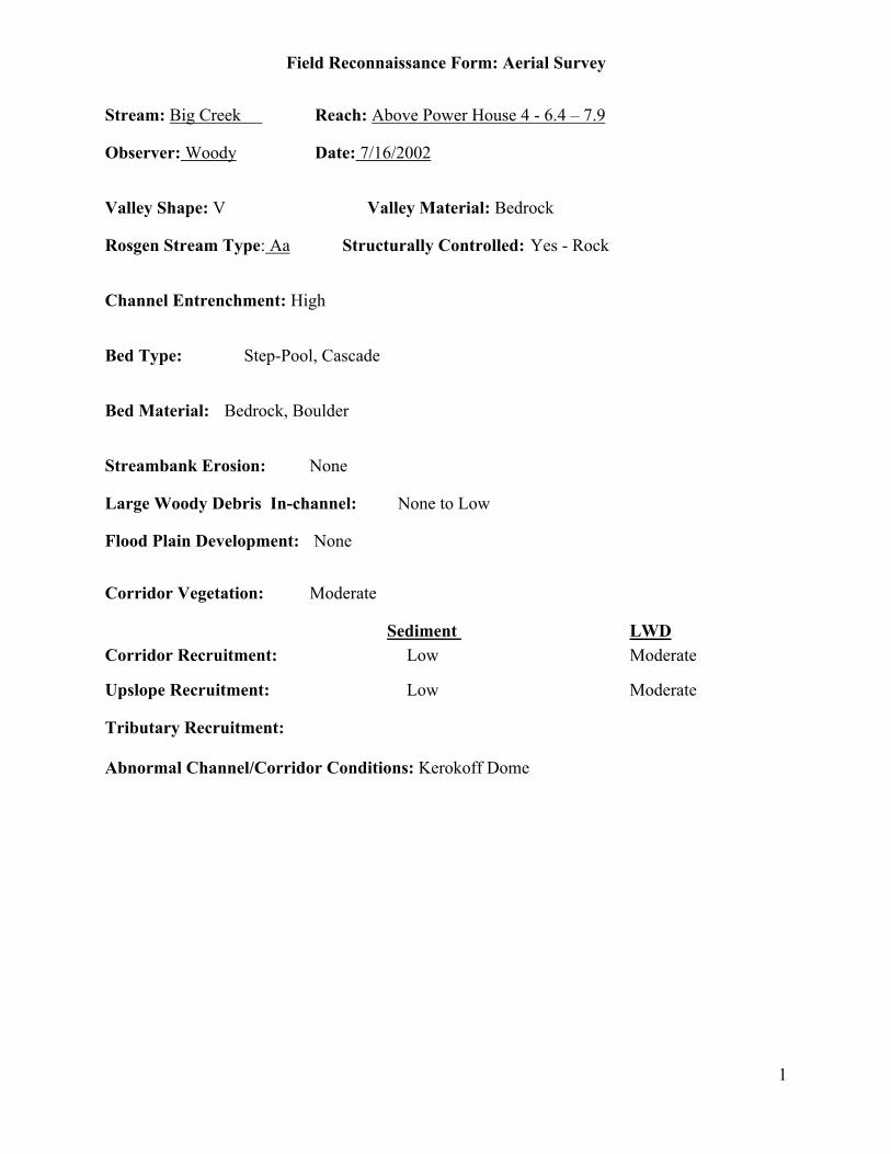
Field Reconnaissance Form: Aerial Survey
1
Stream: Big Creek Reach: Above Power House 4 - 6.4 – 7.9
Observer: Woody Date: 7/16/2002
Valley Shape: V Valley Material: Bedrock
Rosgen Stream Type: Aa Structurally Controlled: Yes - Rock
Channel Entrenchment: High
Bed Type: Step-Pool, Cascade
Bed Material: Bedrock, Boulder
Streambank Erosion: None
Large Woody Debris In-channel: None to Low
Flood Plain Development: None
Corridor Vegetation: Moderate
Sediment LWDCorridor Recruitment: Low Moderate
Upslope Recruitment: Low Moderate
Tributary Recruitment:
Abnormal Channel/Corridor Conditions: Kerokoff Dome

Field Reconnaissance Form: Aerial Survey
2
Streambank Erosion
Bank Material: Bedrock
StreambankVegetation Cover: 0-25%
Bank Erosion: 0-5%
Lateral Migration: No
Describe indicators for lateral migration:
Upslope Sediment Recruitment
Upslope Material: Bedrock
Upslope vegetation: Moderate
Active Erosion: None
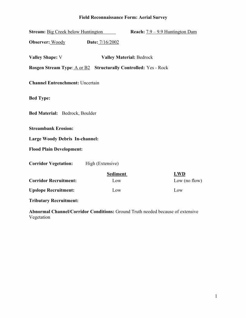
Field Reconnaissance Form: Aerial Survey
1
Stream: Big Creek below Huntington Reach: 7.9 – 9.9 Huntington Dam
Observer: Woody Date: 7/16/2002
Valley Shape: V Valley Material: Bedrock
Rosgen Stream Type: A or B2 Structurally Controlled: Yes - Rock
Channel Entrenchment: Uncertain
Bed Type:
Bed Material: Bedrock, Boulder
Streambank Erosion:
Large Woody Debris In-channel:
Flood Plain Development:
Corridor Vegetation: High (Extensive)
Sediment LWDCorridor Recruitment: Low Low (no flow)
Upslope Recruitment: Low Low
Tributary Recruitment:
Abnormal Channel/Corridor Conditions: Ground Truth needed because of extensiveVegetation

Field Reconnaissance Form: Aerial Survey
2
Streambank Erosion
Bank Material:
StreambankVegetation Cover:
Bank Erosion:
Lateral Migration:
Describe indicators for lateral migration:
Upslope Sediment Recruitment
Upslope Material:
Upslope vegetation:
Active Erosion:
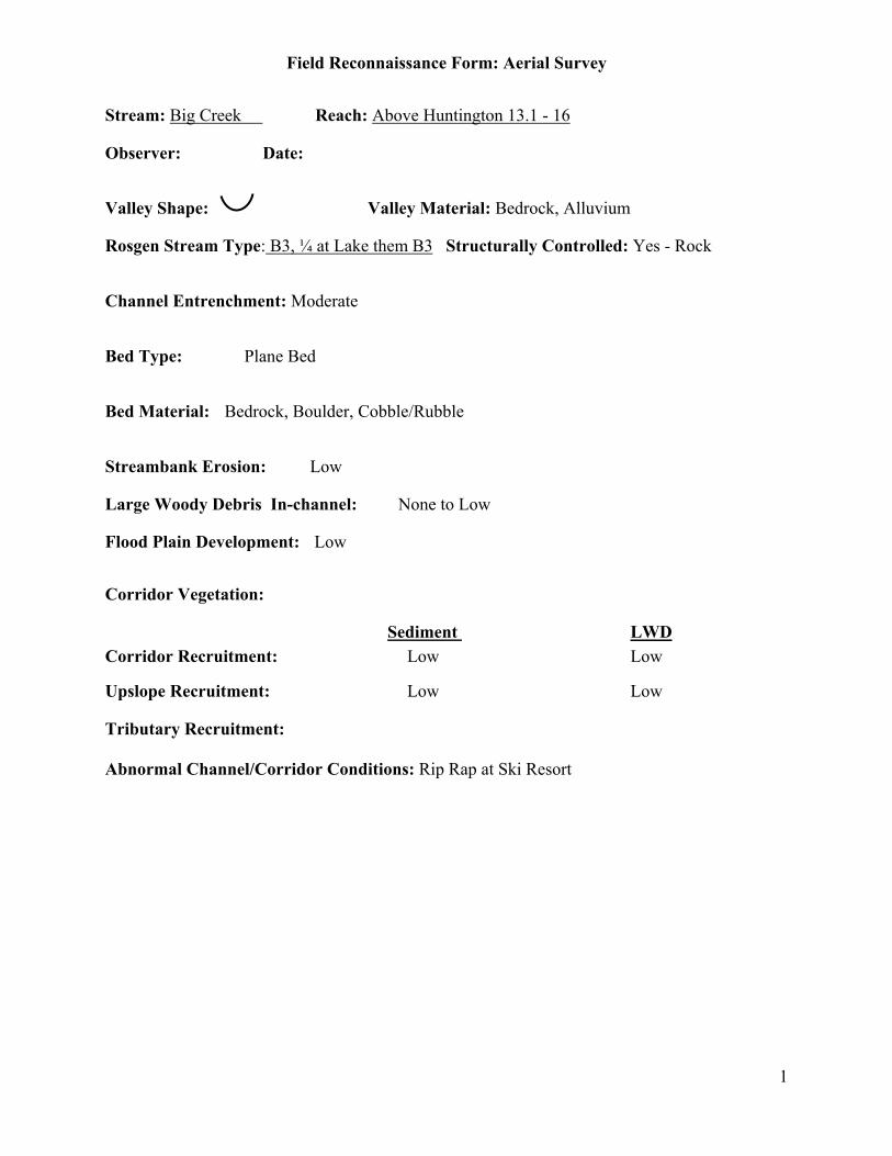
Field Reconnaissance Form: Aerial Survey
1
Stream: Big Creek Reach: Above Huntington 13.1 - 16
Observer: Date:
Valley Shape: Valley Material: Bedrock, Alluvium
Rosgen Stream Type: B3, ¼ at Lake them B3 Structurally Controlled: Yes - Rock
Channel Entrenchment: Moderate
Bed Type: Plane Bed
Bed Material: Bedrock, Boulder, Cobble/Rubble
Streambank Erosion: Low
Large Woody Debris In-channel: None to Low
Flood Plain Development: Low
Corridor Vegetation:
Sediment LWDCorridor Recruitment: Low Low
Upslope Recruitment: Low Low
Tributary Recruitment:
Abnormal Channel/Corridor Conditions: Rip Rap at Ski Resort
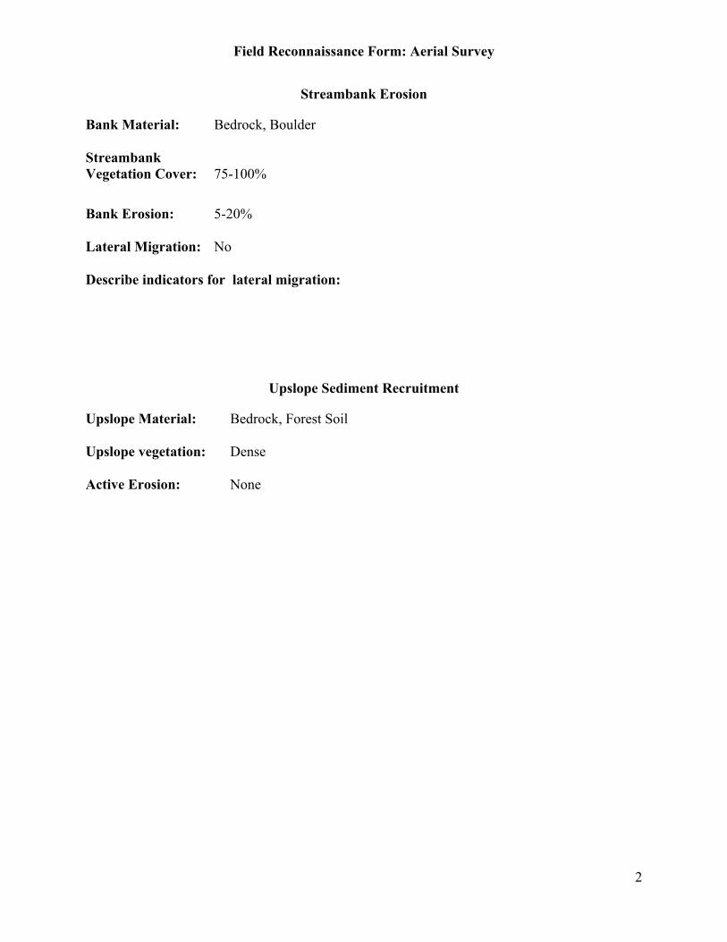
Field Reconnaissance Form: Aerial Survey
2
Streambank Erosion
Bank Material: Bedrock, Boulder
StreambankVegetation Cover: 75-100%
Bank Erosion: 5-20%
Lateral Migration: No
Describe indicators for lateral migration:
Upslope Sediment Recruitment
Upslope Material: Bedrock, Forest Soil
Upslope vegetation: Dense
Active Erosion: None

Field Reconnaissance Form: Aerial Survey
1
Stream: Big Creek Reach: 16 – 16.5
Observer: Date:
Valley Shape: V Valley Material: Bedrock
Rosgen Stream Type: Aa+ Structurally Controlled: Yes - Rock
Channel Entrenchment: High
Bed Type: Step-Pool, Cascade
Bed Material: Bedrock, Boulder
Streambank Erosion: None
Large Woody Debris In-channel: None to Low
Flood Plain Development: None
Corridor Vegetation: Moderate
Sediment LWDCorridor Recruitment: Low Low
Upslope Recruitment: Low Low
Tributary Recruitment:
Abnormal Channel/Corridor Conditions:

Field Reconnaissance Form: Aerial Survey
2
Streambank Erosion
Bank Material: Bedrock
StreambankVegetation Cover: 0-25%
Bank Erosion: 0-5%
Lateral Migration: No
Describe indicators for lateral migration:
Upslope Sediment Recruitment
Upslope Material: Bedrock
Upslope vegetation: Moderate
Active Erosion: None

Field Reconnaissance Form: Aerial Survey
1
Stream: Reach: Billy
Observer: Date:
Valley Shape: V Valley Material:
Rosgen Stream Type: Aa+ Structurally Controlled:
Channel Entrenchment:
Bed Type:
Bed Material:
Streambank Erosion:
Large Woody Debris In-channel:
Flood Plain Development:
Corridor Vegetation:
Sediment LWDCorridor Recruitment:
Upslope Recruitment:
Tributary Recruitment:
Abnormal Channel/Corridor Conditions: Well Timbered, might have to visit on the ground
Field Reconnaissance Form: Aerial Survey
2
Streambank Erosion
Bank Material:
StreambankVegetation Cover:
Bank Erosion:
Lateral Migration:
Describe indicators for lateral migration:
Upslope Sediment Recruitment
Upslope Material:
Upslope vegetation:
Active Erosion:

Field Reconnaissance Form: Aerial Survey
1
Stream: Chiquito Reach:
Observer: Date:
Valley Shape: Valley Material:
Rosgen Stream Type: B 4 or 5 Structurally Controlled:
Channel Entrenchment:
Bed Type:
Bed Material:
Streambank Erosion:
Large Woody Debris In-channel:
Flood Plain Development: Limited
Corridor Vegetation: Moderate
Sediment LWDCorridor Recruitment: Moderate Low
Upslope Recruitment: Moderate Low
Tributary Recruitment:
Abnormal Channel/Corridor Conditions: Can Drive In
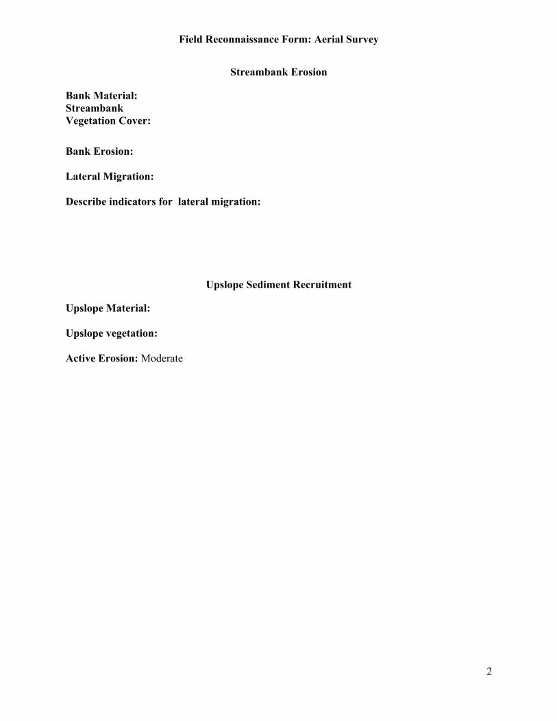
Field Reconnaissance Form: Aerial Survey
2
Streambank Erosion
Bank Material:StreambankVegetation Cover:
Bank Erosion:
Lateral Migration:
Describe indicators for lateral migration:
Upslope Sediment Recruitment
Upslope Material:
Upslope vegetation:
Active Erosion: Moderate

Field Reconnaissance Form: Aerial Survey
1
Stream: Chiquito Reach:
Observer: Date:
Valley Shape: Valley Material: Colluvium
Rosgen Stream Type: B Structurally Controlled: No
Channel Entrenchment: Moderate
Bed Type: Pool/Riffle,Plane Bed
Bed Material: Cobble/Rubble, Mostly Gravel and Sand
Streambank Erosion: Low
Large Woody Debris In-channel: None to Low
Flood Plain Development: Low
Corridor Vegetation: Moderate
Sediment LWDCorridor Recruitment: Moderate Low
Upslope Recruitment: Moderate Low
Tributary Recruitment: Active- small lake deposition
Abnormal Channel/Corridor Conditions: Can Drive in
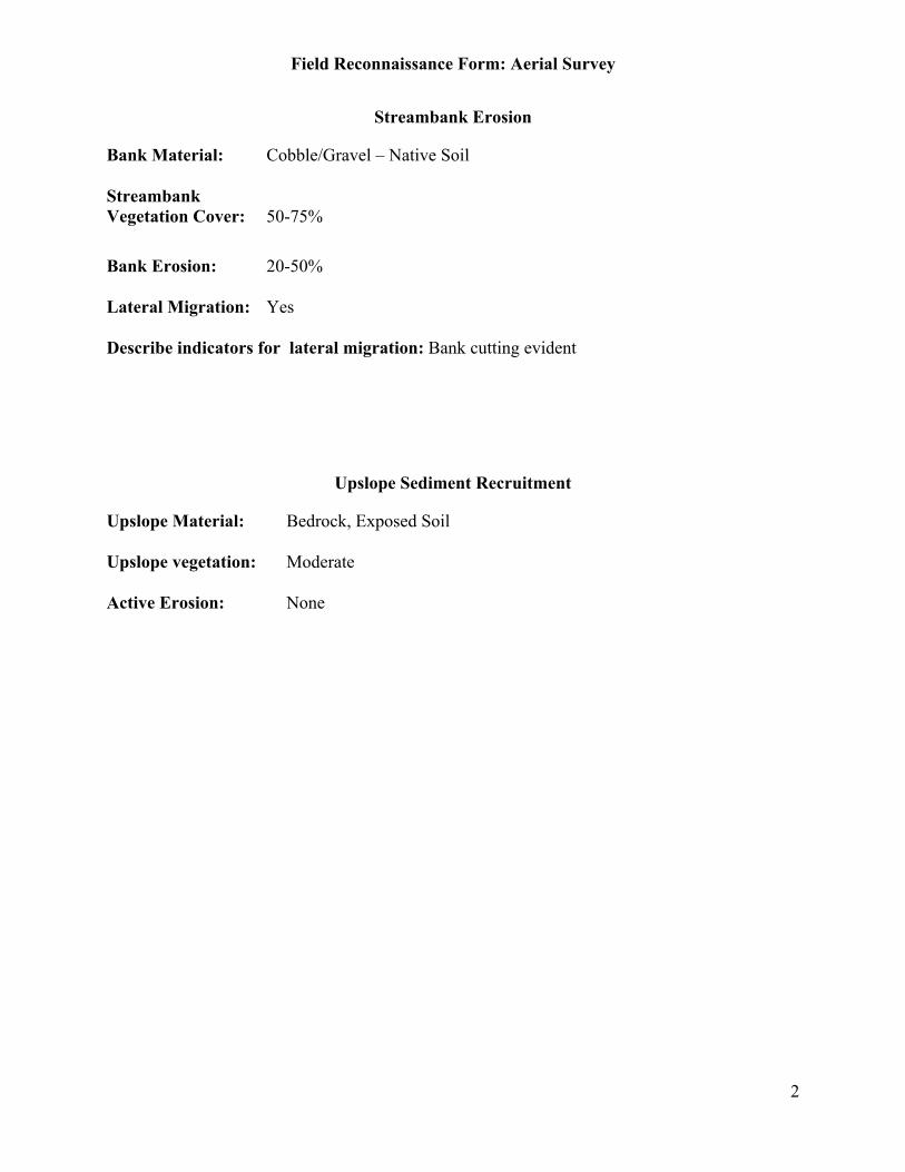
Field Reconnaissance Form: Aerial Survey
2
Streambank Erosion
Bank Material: Cobble/Gravel – Native Soil
StreambankVegetation Cover: 50-75%
Bank Erosion: 20-50%
Lateral Migration: Yes
Describe indicators for lateral migration: Bank cutting evident
Upslope Sediment Recruitment
Upslope Material: Bedrock, Exposed Soil
Upslope vegetation: Moderate
Active Erosion: None
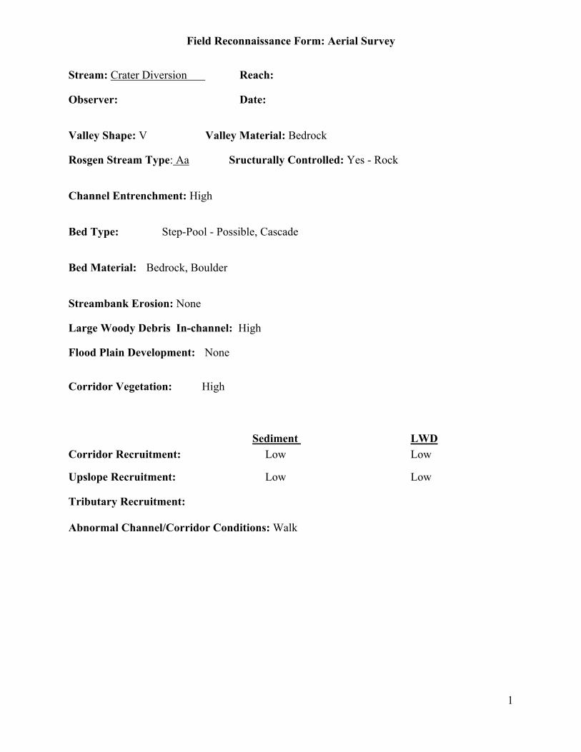
Field Reconnaissance Form: Aerial Survey
1
Stream: Crater Diversion Reach:
Observer: Date:
Valley Shape: V Valley Material: Bedrock
Rosgen Stream Type: Aa Sructurally Controlled: Yes - Rock
Channel Entrenchment: High
Bed Type: Step-Pool - Possible, Cascade
Bed Material: Bedrock, Boulder
Streambank Erosion: None
Large Woody Debris In-channel: High
Flood Plain Development: None
Corridor Vegetation: High
Sediment LWDCorridor Recruitment: Low Low
Upslope Recruitment: Low Low
Tributary Recruitment:
Abnormal Channel/Corridor Conditions: Walk

Field Reconnaissance Form: Aerial Survey
2
Streambank Erosion
Bank Material: Bedrock
StreambankVegetation Cover: 50-75%
Bank Erosion: 0-5%
Lateral Migration: No
Describe indicators for lateral migration:
Upslope Sediment Recruitment
Upslope Material: Bedrock
Upslope vegetation: Scant
Active Erosion: None
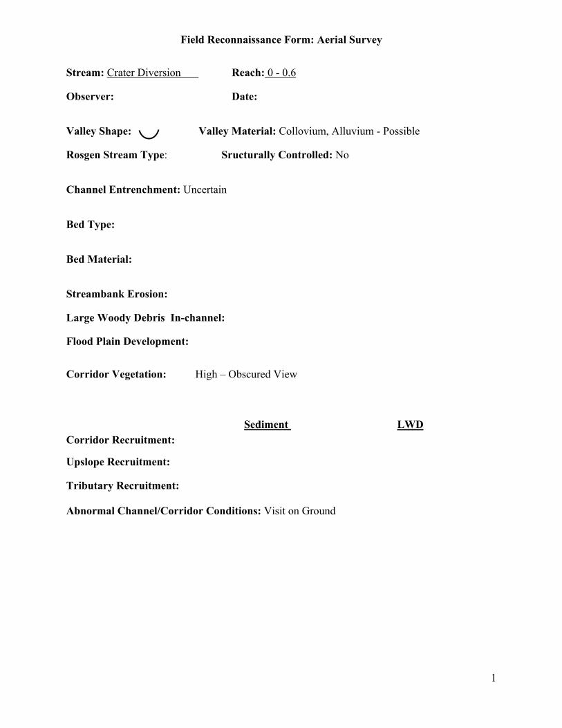
Field Reconnaissance Form: Aerial Survey
1
Stream: Crater Diversion Reach: 0 - 0.6
Observer: Date:
Valley Shape: Valley Material: Collovium, Alluvium - Possible
Rosgen Stream Type: Sructurally Controlled: No
Channel Entrenchment: Uncertain
Bed Type:
Bed Material:
Streambank Erosion:
Large Woody Debris In-channel:
Flood Plain Development:
Corridor Vegetation: High – Obscured View
Sediment LWDCorridor Recruitment:
Upslope Recruitment:
Tributary Recruitment:
Abnormal Channel/Corridor Conditions: Visit on Ground

Field Reconnaissance Form: Aerial Survey
2
Streambank Erosion
Bank Material:
StreambankVegetation Cover:
Bank Erosion:
Lateral Migration:
Describe indicators for lateral migration:
Upslope Sediment Recruitment
Upslope Material:
Upslope vegetation:
Active Erosion:
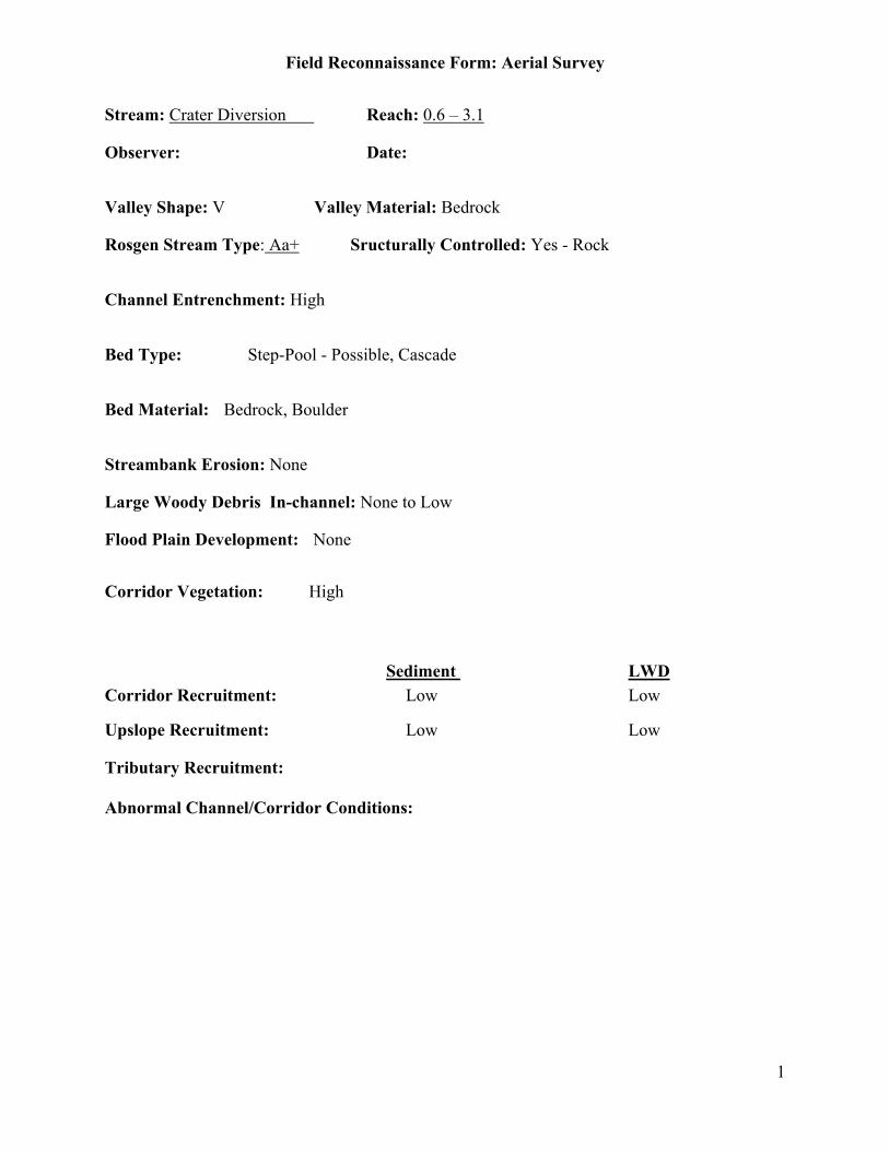
Field Reconnaissance Form: Aerial Survey
1
Stream: Crater Diversion Reach: 0.6 – 3.1
Observer: Date:
Valley Shape: V Valley Material: Bedrock
Rosgen Stream Type: Aa+ Sructurally Controlled: Yes - Rock
Channel Entrenchment: High
Bed Type: Step-Pool - Possible, Cascade
Bed Material: Bedrock, Boulder
Streambank Erosion: None
Large Woody Debris In-channel: None to Low
Flood Plain Development: None
Corridor Vegetation: High
Sediment LWDCorridor Recruitment: Low Low
Upslope Recruitment: Low Low
Tributary Recruitment:
Abnormal Channel/Corridor Conditions:

Field Reconnaissance Form: Aerial Survey
2
Streambank Erosion
Bank Material: Bedrock
StreambankVegetation Cover: 50-75%
Bank Erosion: 0-5%
Lateral Migration: No
Describe indicators for lateral migration:
Upslope Sediment Recruitment
Upslope Material: Bedrock
Upslope vegetation: Scant
Active Erosion: None

Field Reconnaissance Form: Aerial Survey
1
Stream: Ely Reach: 0-.9
Observer: Woody Date:
Valley Shape: U Valley Material: Bedrock
Rosgen Stream Type: Aa+ 0.0 – 0.3, A2 0.3 – 0.9 Structurally Controlled: Yes - Rock
Channel Entrenchment: High
Bed Type: Step-Pool, Cascade
Bed Material: Bedrock, Boulder
Streambank Erosion: None
Large Woody Debris In-channel: None to Low
Flood Plain Development: None
Corridor Vegetation: Moderate
Sediment LWDCorridor Recruitment: Low Low
Upslope Recruitment: Low Low
Tributary Recruitment:
Abnormal Channel/Corridor Conditions:
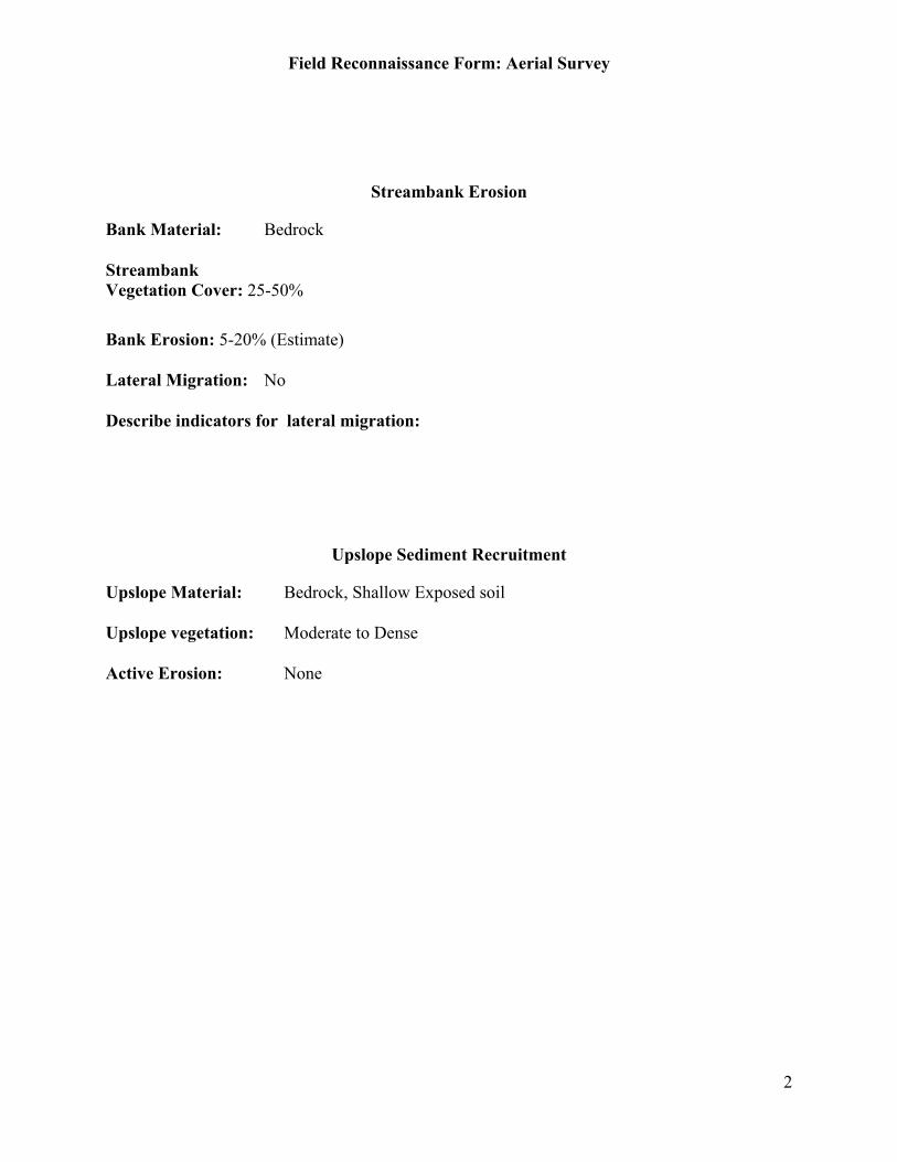
Field Reconnaissance Form: Aerial Survey
2
Streambank Erosion
Bank Material: Bedrock
StreambankVegetation Cover: 25-50%
Bank Erosion: 5-20% (Estimate)
Lateral Migration: No
Describe indicators for lateral migration:
Upslope Sediment Recruitment
Upslope Material: Bedrock, Shallow Exposed soil
Upslope vegetation: Moderate to Dense
Active Erosion: None
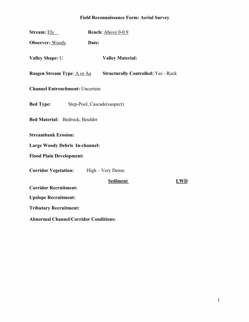
Field Reconnaissance Form: Aerial Survey
1
Stream: Ely Reach: Above 0-0.9
Observer: Woody Date:
Valley Shape: U Valley Material:
Rosgen Stream Type: A or Aa Structurally Controlled: Yes - Rock
Channel Entrenchment: Uncertain
Bed Type: Step-Pool, Cascade(suspect)
Bed Material: Bedrock, Boulder
Streambank Erosion:
Large Woody Debris In-channel:
Flood Plain Development:
Corridor Vegetation: High – Very Dense
Sediment LWDCorridor Recruitment:
Upslope Recruitment:
Tributary Recruitment:
Abnormal Channel/Corridor Conditions:

Field Reconnaissance Form: Aerial Survey
2
Streambank Erosion
Bank Material:
StreambankVegetation Cover:
Bank Erosion:
Lateral Migration:
Describe indicators for lateral migration:
Upslope Sediment Recruitment
Upslope Material:
Upslope vegetation:
Active Erosion:
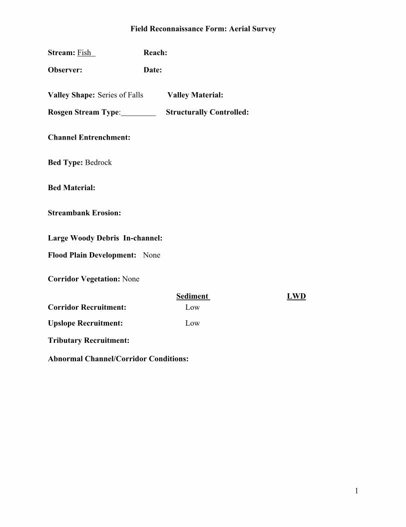
Field Reconnaissance Form: Aerial Survey
1
Stream: Fish Reach:
Observer: Date:
Valley Shape: Series of Falls Valley Material:
Rosgen Stream Type: Structurally Controlled:
Channel Entrenchment:
Bed Type: Bedrock
Bed Material:
Streambank Erosion:
Large Woody Debris In-channel:
Flood Plain Development: None
Corridor Vegetation: None
Sediment LWDCorridor Recruitment: Low
Upslope Recruitment: Low
Tributary Recruitment:
Abnormal Channel/Corridor Conditions:
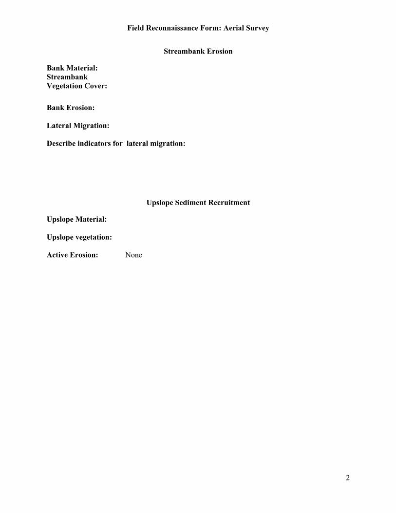
Field Reconnaissance Form: Aerial Survey
2
Streambank Erosion
Bank Material:StreambankVegetation Cover:
Bank Erosion:
Lateral Migration:
Describe indicators for lateral migration:
Upslope Sediment Recruitment
Upslope Material:
Upslope vegetation:
Active Erosion: None
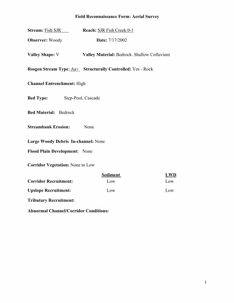
Field Reconnaissance Form: Aerial Survey
1
Stream: Fish SJR Reach: SJR Fish Creek 0-1
Observer: Woody Date: 7/17/2002
Valley Shape: V Valley Material: Bedrock. Shallow Colluvium
Rosgen Stream Type: Aa+ Structurally Controlled: Yes - Rock
Channel Entrenchment: High
Bed Type: Step-Pool, Cascade
Bed Material: Bedrock
Streambank Erosion: None
Large Woody Debris In-channel: None
Flood Plain Development: None
Corridor Vegetation: None to Low
Sediment LWDCorridor Recruitment: Low Low
Upslope Recruitment: Low Low
Tributary Recruitment:
Abnormal Channel/Corridor Conditions:

Field Reconnaissance Form: Aerial Survey
2
Streambank Erosion
Bank Material: Bedrock
StreambankVegetation Cover: 0-25%
Bank Erosion: 0-5%
Lateral Migration: No
Describe indicators for lateral migration:
Upslope Sediment Recruitment
Upslope Material: Bedrock, Shallow Soil
Upslope vegetation: Scant
Active Erosion: None
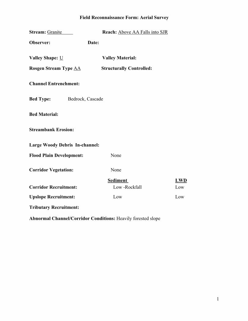
Field Reconnaissance Form: Aerial Survey
1
Stream: Granite Reach: Above AA Falls into SJR
Observer: Date:
Valley Shape: U Valley Material:
Rosgen Stream Type AA Structurally Controlled:
Channel Entrenchment:
Bed Type: Bedrock, Cascade
Bed Material:
Streambank Erosion:
Large Woody Debris In-channel:
Flood Plain Development: None
Corridor Vegetation: None
Sediment LWDCorridor Recruitment: Low -Rockfall Low
Upslope Recruitment: Low Low
Tributary Recruitment:
Abnormal Channel/Corridor Conditions: Heavily forested slope

Field Reconnaissance Form: Aerial Survey
2
Streambank Erosion
Bank Material:StreambankVegetation Cover:
Bank Erosion:
Lateral Migration:
Describe indicators for lateral migration:
Upslope Sediment Recruitment
Upslope Material:
Upslope vegetation:
Active Erosion: None
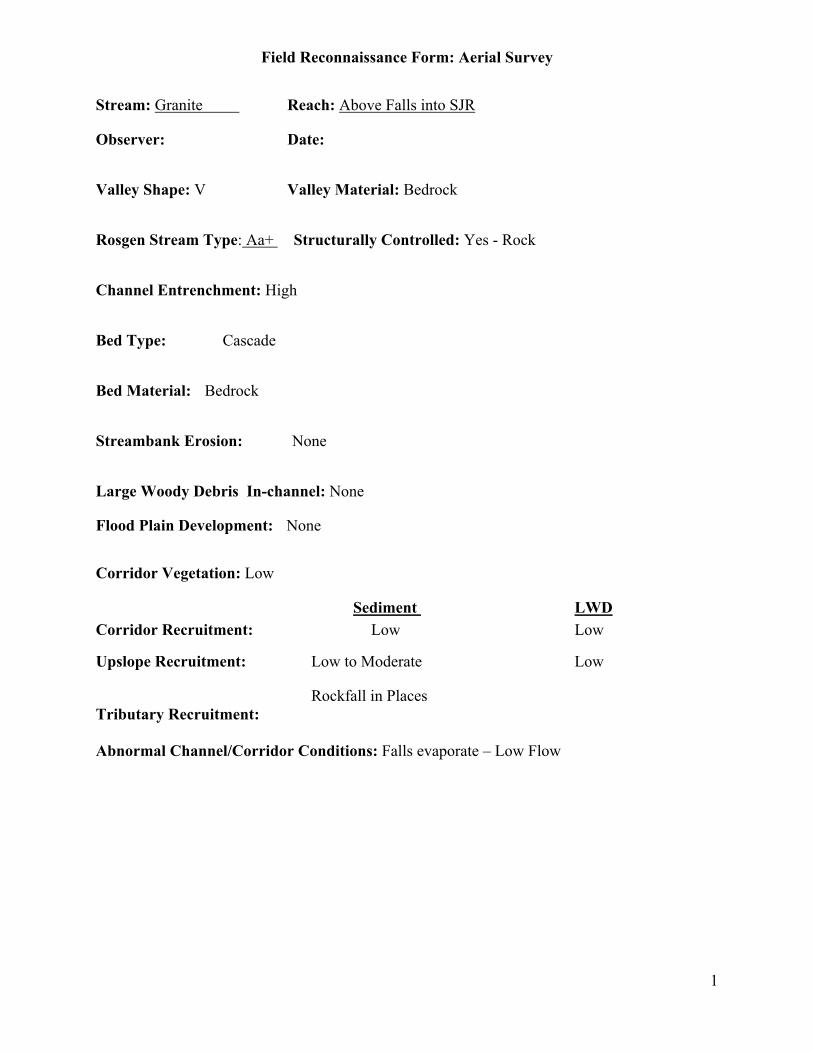
Field Reconnaissance Form: Aerial Survey
1
Stream: Granite Reach: Above Falls into SJR
Observer: Date:
Valley Shape: V Valley Material: Bedrock
Rosgen Stream Type: Aa+ Structurally Controlled: Yes - Rock
Channel Entrenchment: High
Bed Type: Cascade
Bed Material: Bedrock
Streambank Erosion: None
Large Woody Debris In-channel: None
Flood Plain Development: None
Corridor Vegetation: Low
Sediment LWDCorridor Recruitment: Low Low
Upslope Recruitment: Low to Moderate Low
Rockfall in PlacesTributary Recruitment:
Abnormal Channel/Corridor Conditions: Falls evaporate – Low Flow
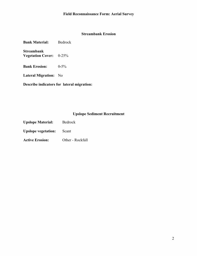
Field Reconnaissance Form: Aerial Survey
2
Streambank Erosion
Bank Material: Bedrock
StreambankVegetation Cover: 0-25%
Bank Erosion: 0-5%
Lateral Migration: No
Describe indicators for lateral migration:
Upslope Sediment Recruitment
Upslope Material: Bedrock
Upslope vegetation: Scant
Active Erosion: Other - Rockfall

Field Reconnaissance Form: Aerial Survey
1
Stream: Reach: Home Camp
Observer: Date:
Valley Shape: Valley Material: Bedrock
Rosgen Stream Type: B3 Structurally Controlled: No
Channel Entrenchment: Moderate
Bed Type: ?
Bed Material: Bedrock
Streambank Erosion: ?
Large Woody Debris In-channel: Moderate to High
Flood Plain Development: Low
Corridor Vegetation: Moderate to High
Sediment LWDCorridor Recruitment: Low High
Upslope Recruitment: Low Moderate
Tributary Recruitment:
Abnormal Channel/Corridor Conditions: Lot of Blowdown, Ground Check

Field Reconnaissance Form: Aerial Survey
2
Streambank Erosion
Bank Material: Bedrock, Boulder
StreambankVegetation Cover: 0-25%
Bank Erosion: 5-20%
Lateral Migration:
Describe indicators for lateral migration:
Upslope Sediment Recruitment
Upslope Material:
Upslope vegetation:
Active Erosion:
Willow Growth and water may show what project effect is where water shut off due to diversion.
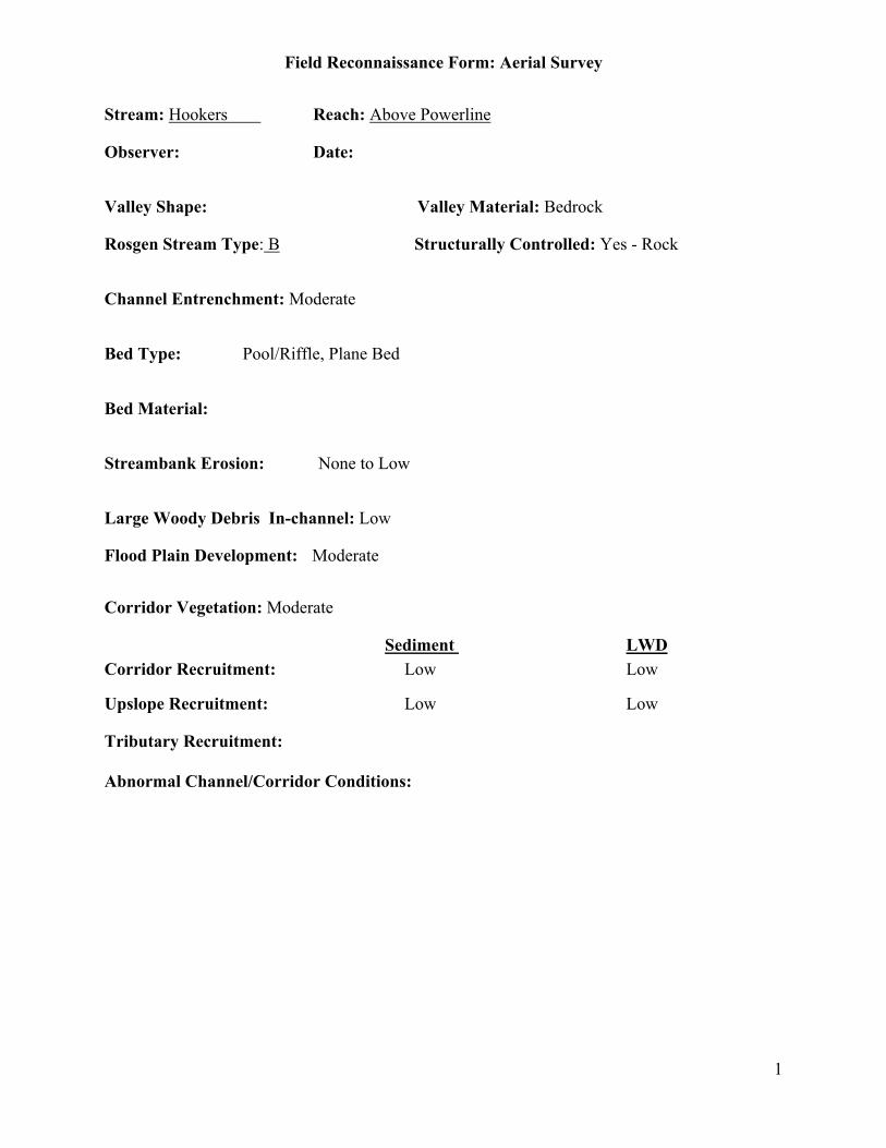
Field Reconnaissance Form: Aerial Survey
1
Stream: Hookers Reach: Above Powerline
Observer: Date:
Valley Shape: Valley Material: Bedrock
Rosgen Stream Type: B Structurally Controlled: Yes - Rock
Channel Entrenchment: Moderate
Bed Type: Pool/Riffle, Plane Bed
Bed Material:
Streambank Erosion: None to Low
Large Woody Debris In-channel: Low
Flood Plain Development: Moderate
Corridor Vegetation: Moderate
Sediment LWDCorridor Recruitment: Low Low
Upslope Recruitment: Low Low
Tributary Recruitment:
Abnormal Channel/Corridor Conditions:

Field Reconnaissance Form: Aerial Survey
2
Streambank Erosion
Bank Material:
StreambankVegetation Cover:
Bank Erosion:
Lateral Migration:
Describe indicators for lateral migration:
Upslope Sediment Recruitment
Upslope Material:
Upslope vegetation:
Active Erosion:
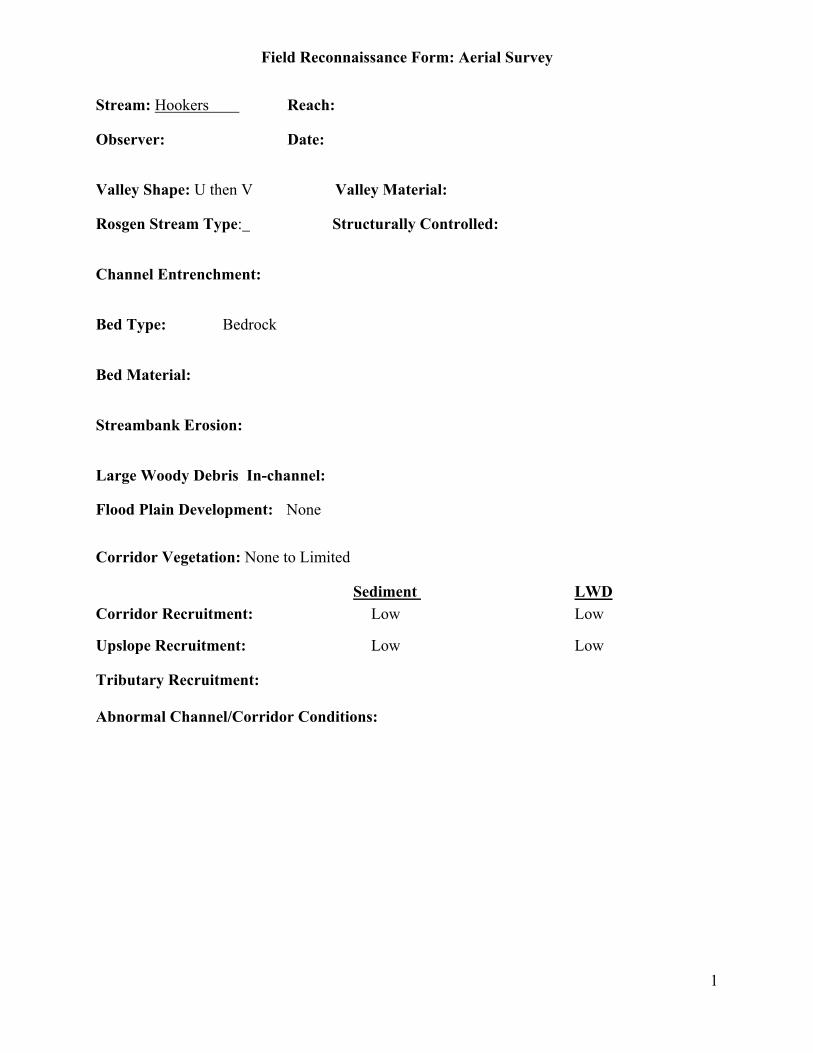
Field Reconnaissance Form: Aerial Survey
1
Stream: Hookers Reach:
Observer: Date:
Valley Shape: U then V Valley Material:
Rosgen Stream Type: Structurally Controlled:
Channel Entrenchment:
Bed Type: Bedrock
Bed Material:
Streambank Erosion:
Large Woody Debris In-channel:
Flood Plain Development: None
Corridor Vegetation: None to Limited
Sediment LWDCorridor Recruitment: Low Low
Upslope Recruitment: Low Low
Tributary Recruitment:
Abnormal Channel/Corridor Conditions:

Field Reconnaissance Form: Aerial Survey
2
Streambank Erosion
Bank Material:StreambankVegetation Cover:
Bank Erosion:
Lateral Migration:
Describe indicators for lateral migration:
Upslope Sediment Recruitment
Upslope Material:
Upslope vegetation:
Active Erosion:

Field Reconnaissance Form: Aerial Survey
1
Stream: Hookers Reach:
Observer: Date:
Valley Shape: Valley Material:
Rosgen Stream Type: B above powerline Structurally Controlled:
Channel Entrenchment:
Bed Type:
Bed Material:
Streambank Erosion:
Large Woody Debris In-channel:
Flood Plain Development: Moderate
Corridor Vegetation: Moderate
Sediment LWDCorridor Recruitment:
Upslope Recruitment:
Tributary Recruitment:
Abnormal Channel/Corridor Conditions:

Field Reconnaissance Form: Aerial Survey
2
Streambank Erosion
Bank Material:StreambankVegetation Cover:
Bank Erosion:
Lateral Migration:
Describe indicators for lateral migration:
Upslope Sediment Recruitment
Upslope Material:
Upslope vegetation:
Active Erosion:
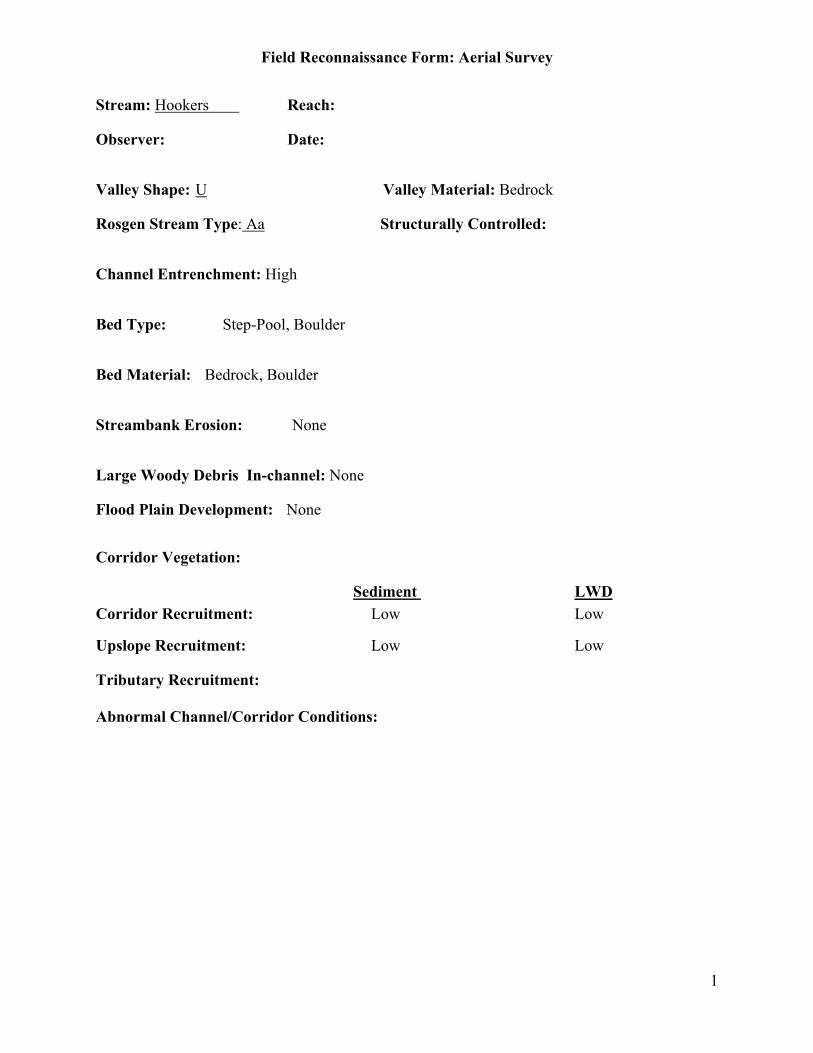
Field Reconnaissance Form: Aerial Survey
1
Stream: Hookers Reach:
Observer: Date:
Valley Shape: U Valley Material: Bedrock
Rosgen Stream Type: Aa Structurally Controlled:
Channel Entrenchment: High
Bed Type: Step-Pool, Boulder
Bed Material: Bedrock, Boulder
Streambank Erosion: None
Large Woody Debris In-channel: None
Flood Plain Development: None
Corridor Vegetation:
Sediment LWDCorridor Recruitment: Low Low
Upslope Recruitment: Low Low
Tributary Recruitment:
Abnormal Channel/Corridor Conditions:

Field Reconnaissance Form: Aerial Survey
2
Streambank Erosion
Bank Material:
StreambankVegetation Cover:
Bank Erosion:
Lateral Migration:
Describe indicators for lateral migration:
Upslope Sediment Recruitment
Upslope Material:
Upslope vegetation:
Active Erosion:
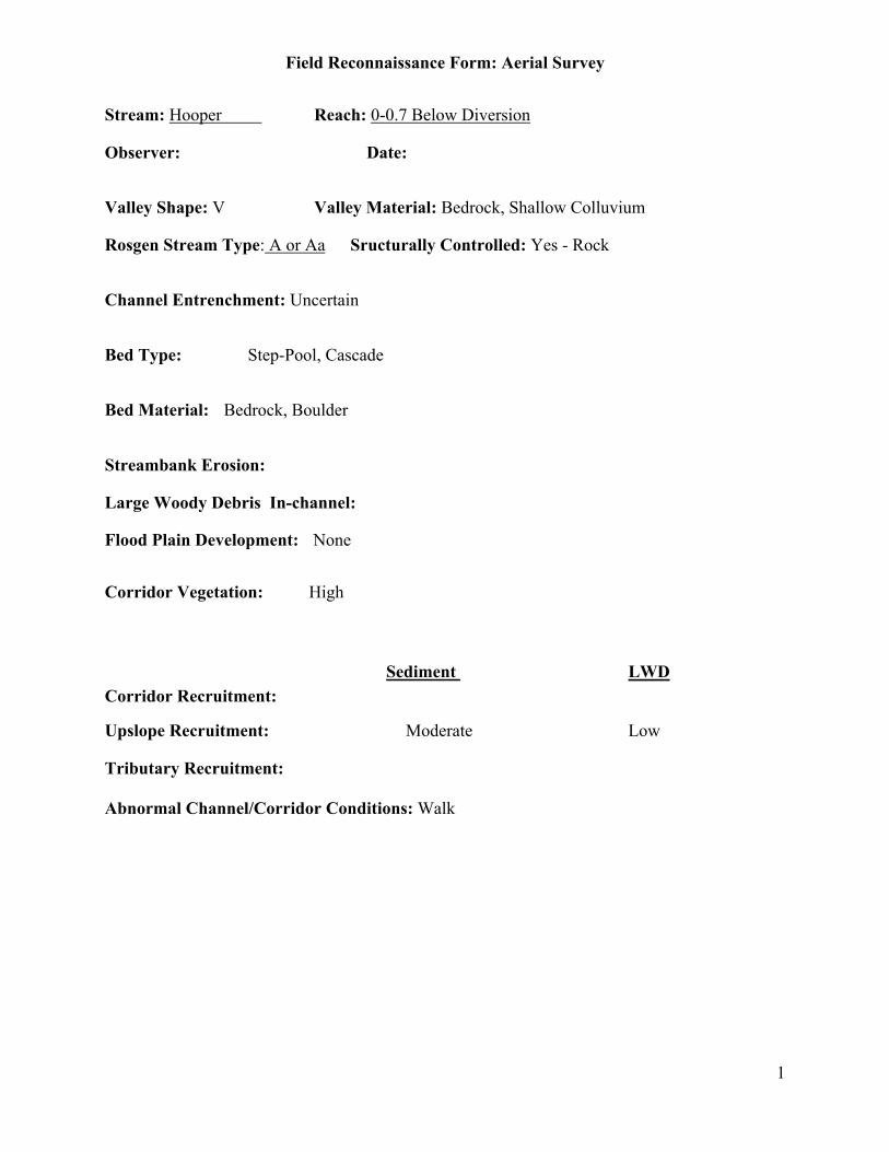
Field Reconnaissance Form: Aerial Survey
1
Stream: Hooper Reach: 0-0.7 Below Diversion
Observer: Date:
Valley Shape: V Valley Material: Bedrock, Shallow Colluvium
Rosgen Stream Type: A or Aa Sructurally Controlled: Yes - Rock
Channel Entrenchment: Uncertain
Bed Type: Step-Pool, Cascade
Bed Material: Bedrock, Boulder
Streambank Erosion:
Large Woody Debris In-channel:
Flood Plain Development: None
Corridor Vegetation: High
Sediment LWDCorridor Recruitment:
Upslope Recruitment: Moderate Low
Tributary Recruitment:
Abnormal Channel/Corridor Conditions: Walk

Field Reconnaissance Form: Aerial Survey
2
Streambank Erosion
Bank Material:
StreambankVegetation Cover:
Bank Erosion:
Lateral Migration:
Describe indicators for lateral migration:
Upslope Sediment Recruitment
Upslope Material:
Upslope vegetation:
Active Erosion:

Field Reconnaissance Form: Aerial Survey
1
Stream: Hooper Reach: 0.7-1.6 Above Diversion
Observer: Date:
Valley Shape: V Valley Material: Bedrock, Colluvium
Rosgen Stream Type: Aa+ Sructurally Controlled: Yes - Rock
Channel Entrenchment: High
Bed Type: Cascade
Bed Material: Bedrock, Boulder
Streambank Erosion: None
Large Woody Debris In-channel: None to Low
Flood Plain Development: None
Corridor Vegetation: High
Sediment LWDCorridor Recruitment: Low Low
Upslope Recruitment: High Low
Tributary Recruitment:
Abnormal Channel/Corridor Conditions: Upper Slope Till exposed and eroding

Field Reconnaissance Form: Aerial Survey
2
Streambank Erosion
Bank Material: Boulder
StreambankVegetation Cover: 75-100%
Bank Erosion: 0-5%
Lateral Migration: No
Describe indicators for lateral migration:
Upslope Sediment Recruitment
Upslope Material: Bedrock, Exposed Till
Upslope vegetation: Scant
Active Erosion: Other – Eroding Till
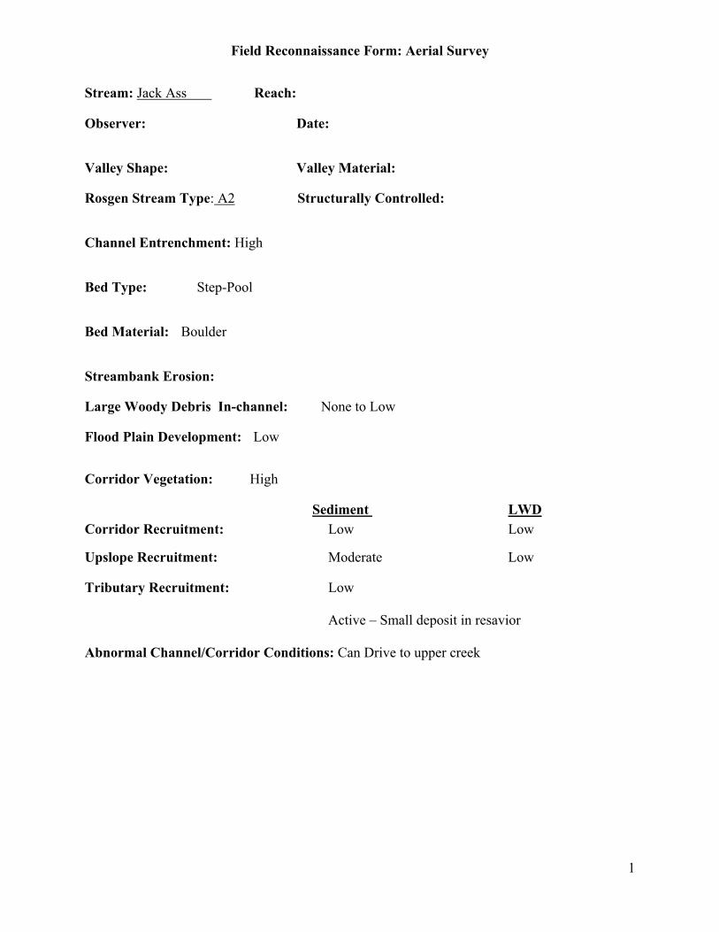
Field Reconnaissance Form: Aerial Survey
1
Stream: Jack Ass Reach:
Observer: Date:
Valley Shape: Valley Material:
Rosgen Stream Type: A2 Structurally Controlled:
Channel Entrenchment: High
Bed Type: Step-Pool
Bed Material: Boulder
Streambank Erosion:
Large Woody Debris In-channel: None to Low
Flood Plain Development: Low
Corridor Vegetation: High
Sediment LWDCorridor Recruitment: Low Low
Upslope Recruitment: Moderate Low
Tributary Recruitment: Low
Active – Small deposit in resavior
Abnormal Channel/Corridor Conditions: Can Drive to upper creek

Field Reconnaissance Form: Aerial Survey
2
Streambank Erosion
Bank Material:
StreambankVegetation Cover:
Bank Erosion:
Lateral Migration:
Describe indicators for lateral migration:
Upslope Sediment Recruitment
Upslope Material: Bedrock, Exposed Soil
Upslope vegetation: Moderate
Active Erosion: None

Field Reconnaissance Form: Aerial Survey
1
Stream: Jose Reach: 0 – 2
Observer: Date:
Valley Shape: V Valley Material: Bedrock Shallow Alluvium
Rosgen Stream Type: A Structurally Controlled: Yes - Rock
Channel Entrenchment: High
Bed Type: Step-Pool, Cascade
Bed Material: Bedrock, Boulder
Streambank Erosion: None
Large Woody Debris In-channel: None to Low
Flood Plain Development: None
Corridor Vegetation: Low
Sediment LWDCorridor Recruitment: Low Low
Upslope Recruitment: Low Low
Tributary Recruitment:
Abnormal Channel/Corridor Conditions:

Field Reconnaissance Form: Aerial Survey
2
Streambank Erosion
Bank Material: Bedrock, Boulder
StreambankVegetation Cover: 0-25%
Bank Erosion: 5-20%
Lateral Migration: No
Describe indicators for lateral migration:
Upslope Sediment Recruitment
Upslope Material: Bedrock, Shallow Soil
Upslope vegetation: Scant
Active Erosion: None
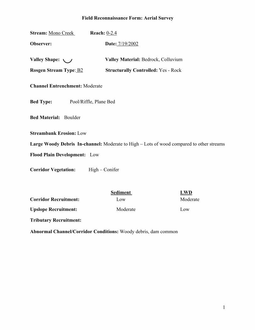
Field Reconnaissance Form: Aerial Survey
1
Stream: Mono Creek Reach: 0-2.4
Observer: Date: 7/19/2002
Valley Shape: Valley Material: Bedrock, Colluvium
Rosgen Stream Type: B2 Structurally Controlled: Yes - Rock
Channel Entrenchment: Moderate
Bed Type: Pool/Riffle, Plane Bed
Bed Material: Boulder
Streambank Erosion: Low
Large Woody Debris In-channel: Moderate to High – Lots of wood compared to other streams
Flood Plain Development: Low
Corridor Vegetation: High – Conifer
Sediment LWDCorridor Recruitment: Low Moderate
Upslope Recruitment: Moderate Low
Tributary Recruitment:
Abnormal Channel/Corridor Conditions: Woody debris, dam common
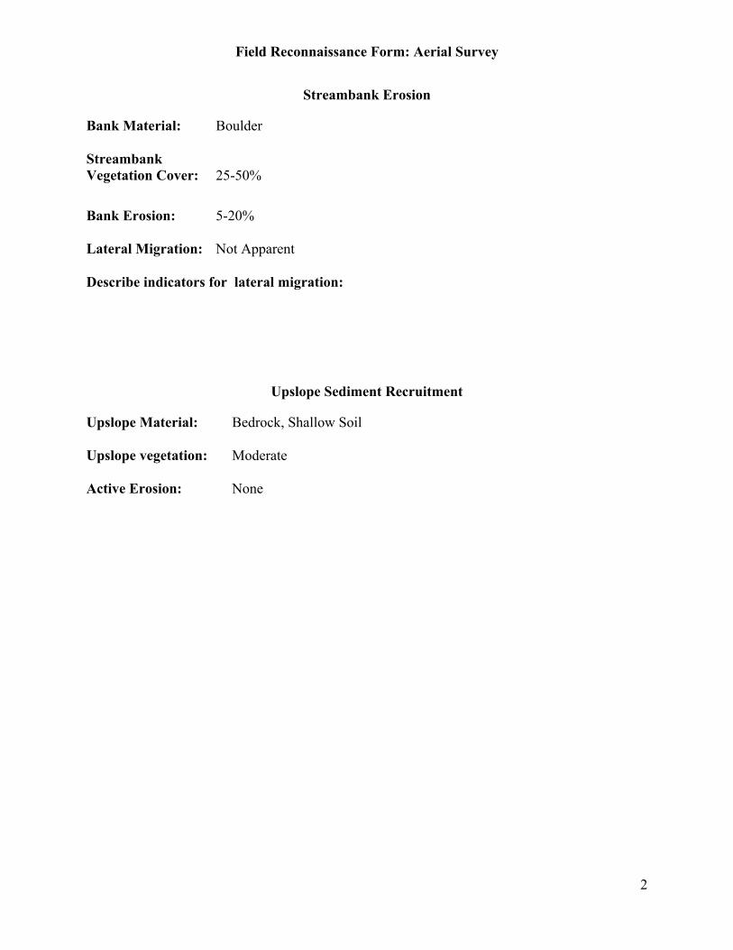
Field Reconnaissance Form: Aerial Survey
2
Streambank Erosion
Bank Material: Boulder
StreambankVegetation Cover: 25-50%
Bank Erosion: 5-20%
Lateral Migration: Not Apparent
Describe indicators for lateral migration:
Upslope Sediment Recruitment
Upslope Material: Bedrock, Shallow Soil
Upslope vegetation: Moderate
Active Erosion: None
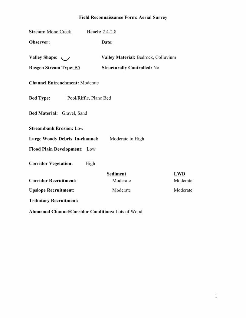
Field Reconnaissance Form: Aerial Survey
1
Stream: Mono Creek Reach: 2.4-2.8
Observer: Date:
Valley Shape: Valley Material: Bedrock, Colluvium
Rosgen Stream Type: B5 Structurally Controlled: No
Channel Entrenchment: Moderate
Bed Type: Pool/Riffle, Plane Bed
Bed Material: Gravel, Sand
Streambank Erosion: Low
Large Woody Debris In-channel: Moderate to High
Flood Plain Development: Low
Corridor Vegetation: High
Sediment LWDCorridor Recruitment: Moderate Moderate
Upslope Recruitment: Moderate Moderate
Tributary Recruitment:
Abnormal Channel/Corridor Conditions: Lots of Wood
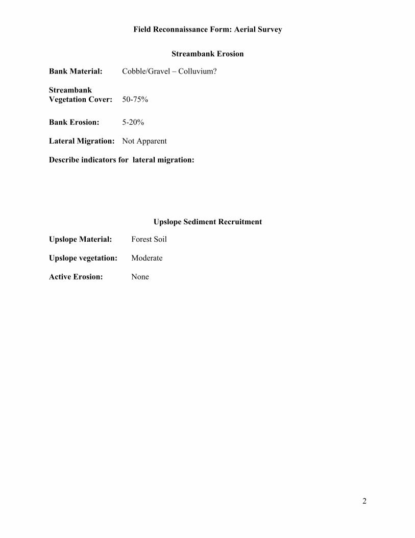
Field Reconnaissance Form: Aerial Survey
2
Streambank Erosion
Bank Material: Cobble/Gravel – Colluvium?
StreambankVegetation Cover: 50-75%
Bank Erosion: 5-20%
Lateral Migration: Not Apparent
Describe indicators for lateral migration:
Upslope Sediment Recruitment
Upslope Material: Forest Soil
Upslope vegetation: Moderate
Active Erosion: None
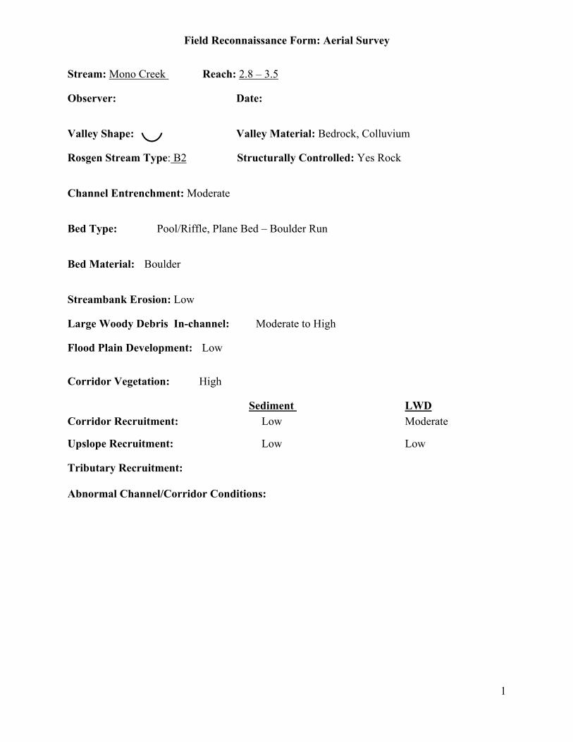
Field Reconnaissance Form: Aerial Survey
1
Stream: Mono Creek Reach: 2.8 – 3.5
Observer: Date:
Valley Shape: Valley Material: Bedrock, Colluvium
Rosgen Stream Type: B2 Structurally Controlled: Yes Rock
Channel Entrenchment: Moderate
Bed Type: Pool/Riffle, Plane Bed – Boulder Run
Bed Material: Boulder
Streambank Erosion: Low
Large Woody Debris In-channel: Moderate to High
Flood Plain Development: Low
Corridor Vegetation: High
Sediment LWDCorridor Recruitment: Low Moderate
Upslope Recruitment: Low Low
Tributary Recruitment:
Abnormal Channel/Corridor Conditions:
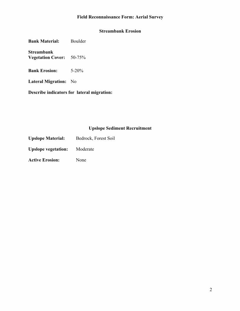
Field Reconnaissance Form: Aerial Survey
2
Streambank Erosion
Bank Material: Boulder
StreambankVegetation Cover: 50-75%
Bank Erosion: 5-20%
Lateral Migration: No
Describe indicators for lateral migration:
Upslope Sediment Recruitment
Upslope Material: Bedrock, Forest Soil
Upslope vegetation: Moderate
Active Erosion: None
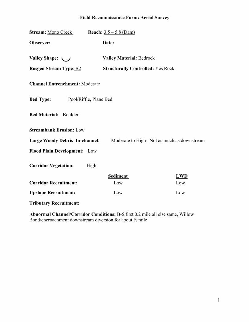
Field Reconnaissance Form: Aerial Survey
1
Stream: Mono Creek Reach: 3.5 – 5.8 (Dam)
Observer: Date:
Valley Shape: Valley Material: Bedrock
Rosgen Stream Type: B2 Structurally Controlled: Yes Rock
Channel Entrenchment: Moderate
Bed Type: Pool/Riffle, Plane Bed
Bed Material: Boulder
Streambank Erosion: Low
Large Woody Debris In-channel: Moderate to High –Not as much as downstream
Flood Plain Development: Low
Corridor Vegetation: High
Sediment LWDCorridor Recruitment: Low Low
Upslope Recruitment: Low Low
Tributary Recruitment:
Abnormal Channel/Corridor Conditions: B-5 first 0.2 mile all else same, WillowBond/encroachment downstream diversion for about ½ mile

Field Reconnaissance Form: Aerial Survey
2
Streambank Erosion
Bank Material: Bedrock, Boulder
StreambankVegetation Cover: 50-75%
Bank Erosion: 0-5%
Lateral Migration: No
Describe indicators for lateral migration:
Upslope Sediment Recruitment
Upslope Material: Bedrock, Forest Soil
Upslope vegetation: Moderate
Active Erosion: None
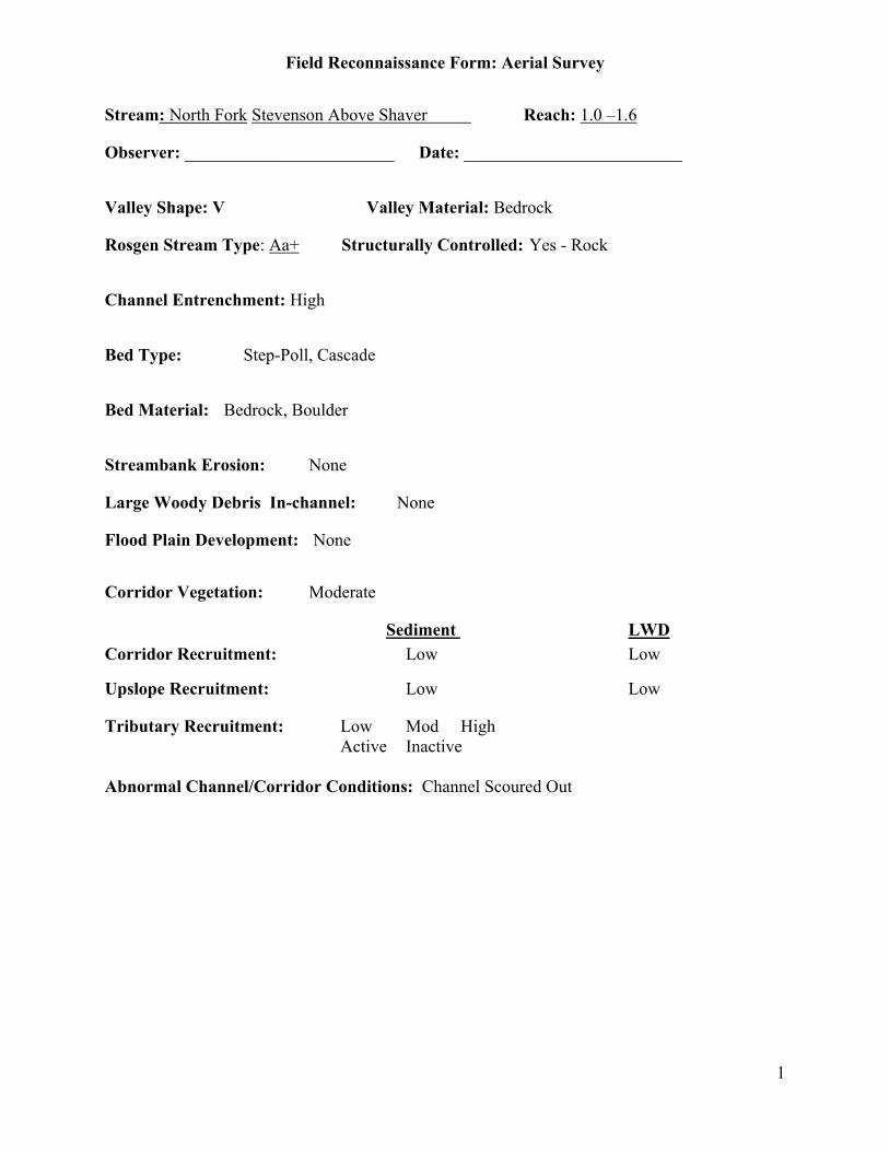
Field Reconnaissance Form: Aerial Survey
1
Stream: North Fork Stevenson Above Shaver Reach: 1.0 –1.6
Observer: ________________________ Date: _________________________
Valley Shape: V Valley Material: Bedrock
Rosgen Stream Type: Aa+ Structurally Controlled: Yes - Rock
Channel Entrenchment: High
Bed Type: Step-Poll, Cascade
Bed Material: Bedrock, Boulder
Streambank Erosion: None
Large Woody Debris In-channel: None
Flood Plain Development: None
Corridor Vegetation: Moderate
Sediment LWDCorridor Recruitment: Low Low
Upslope Recruitment: Low Low
Tributary Recruitment: Low Mod HighActive Inactive
Abnormal Channel/Corridor Conditions: Channel Scoured Out

Field Reconnaissance Form: Aerial Survey
2
Streambank Erosion
Bank Material: BedrockStreambankVegetation Cover: 0-25%
Bank Erosion: 5-20%
Lateral Migration: NoDescribe indicators for lateral migration:
Upslope Sediment Recruitment
Upslope Material: BedrockUpslope vegetation: ModerateActive Erosion: None
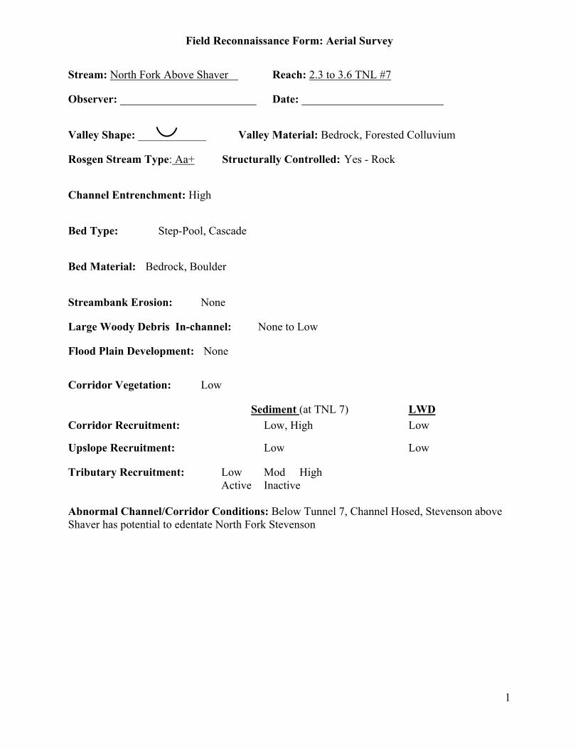
Field Reconnaissance Form: Aerial Survey
1
Stream: North Fork Above Shaver Reach: 2.3 to 3.6 TNL #7
Observer: ________________________ Date: _________________________
Valley Shape: ____________ Valley Material: Bedrock, Forested Colluvium
Rosgen Stream Type: Aa+ Structurally Controlled: Yes - Rock
Channel Entrenchment: High
Bed Type: Step-Pool, Cascade
Bed Material: Bedrock, Boulder
Streambank Erosion: None
Large Woody Debris In-channel: None to Low
Flood Plain Development: None
Corridor Vegetation: Low
Sediment (at TNL 7) LWDCorridor Recruitment: Low, High Low
Upslope Recruitment: Low Low
Tributary Recruitment: Low Mod HighActive Inactive
Abnormal Channel/Corridor Conditions: Below Tunnel 7, Channel Hosed, Stevenson aboveShaver has potential to edentate North Fork Stevenson

Field Reconnaissance Form: Aerial Survey
2
Streambank Erosion
Bank Material: Bedrock, Cobble/GravelStreambankVegetation Cover: 0-25%
Bank Erosion: 5-20%
Lateral Migration: No, incision and widening
Describe indicators for lateral migration:
Upslope Sediment Recruitment
Upslope Material: Forest SoilUpslope vegetation: DenseActive Erosion: None

Field Reconnaissance Form: Aerial Survey
1
Stream: North Slide Reach: 0-1.2
Observer: Date:
Valley Shape: V Valley Material: Bedrock, Colluvium Big Debris Fan at bottom
Rosgen Stream Type: Aa+ Sructurally Controlled: Yes - Rock
Channel Entrenchment: High
Bed Type: Cascade
Bed Material: Bedrock, Boulder - Rockfall
Streambank Erosion: None to Low
Large Woody Debris In-channel: None to Low
Flood Plain Development: None
Corridor Vegetation: High
Sediment LWDCorridor Recruitment: Low Low
Upslope Recruitment: Moderate Low
Tributary Recruitment:
Abnormal Channel/Corridor Conditions: Change at top 1.2
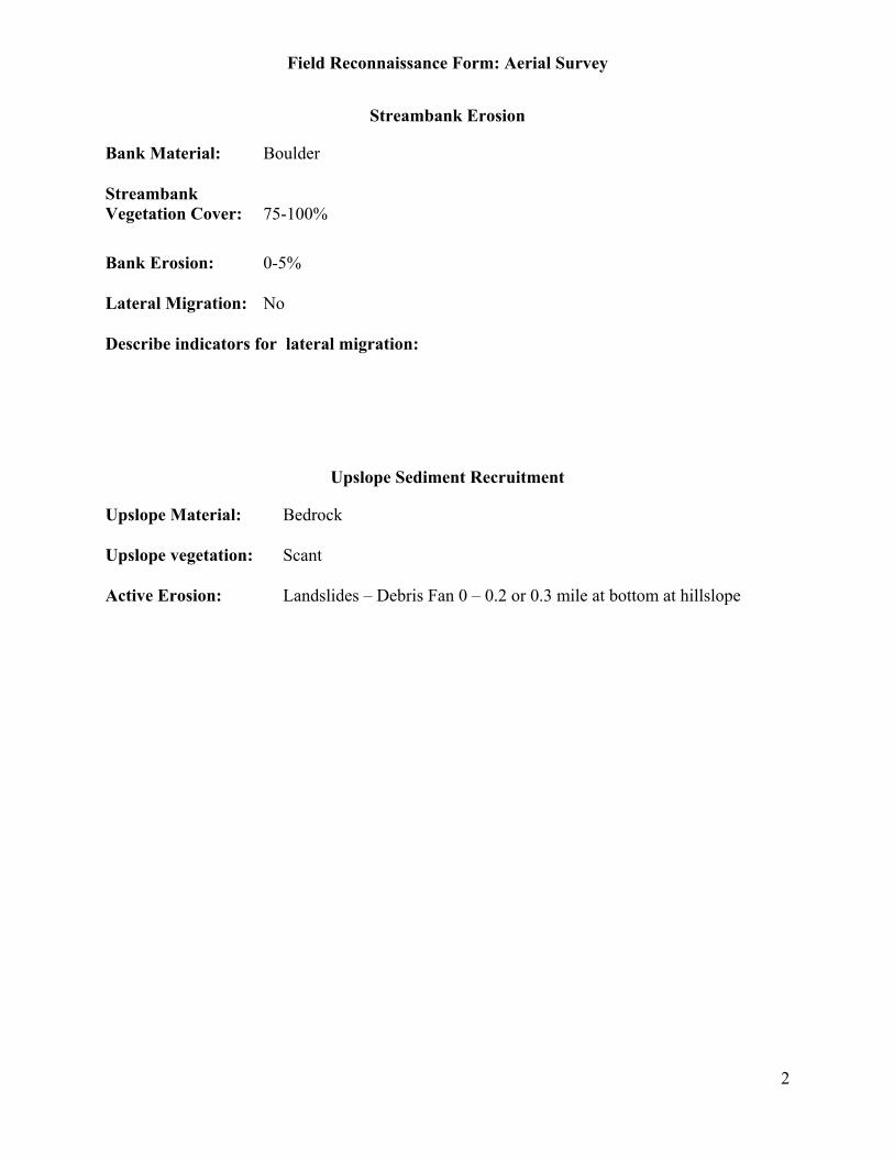
Field Reconnaissance Form: Aerial Survey
2
Streambank Erosion
Bank Material: Boulder
StreambankVegetation Cover: 75-100%
Bank Erosion: 0-5%
Lateral Migration: No
Describe indicators for lateral migration:
Upslope Sediment Recruitment
Upslope Material: Bedrock
Upslope vegetation: Scant
Active Erosion: Landslides – Debris Fan 0 – 0.2 or 0.3 mile at bottom at hillslope
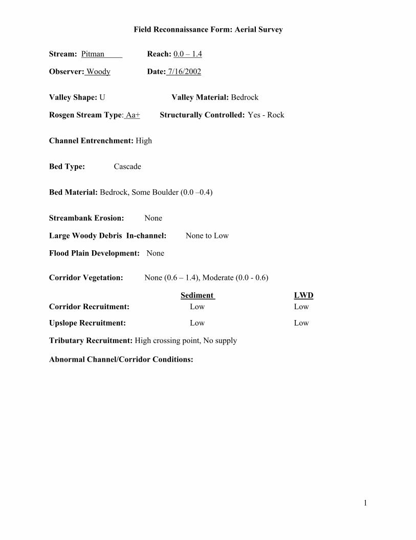
Field Reconnaissance Form: Aerial Survey
1
Stream: Pitman Reach: 0.0 – 1.4
Observer: Woody Date: 7/16/2002
Valley Shape: U Valley Material: Bedrock
Rosgen Stream Type: Aa+ Structurally Controlled: Yes - Rock
Channel Entrenchment: High
Bed Type: Cascade
Bed Material: Bedrock, Some Boulder (0.0 –0.4)
Streambank Erosion: None
Large Woody Debris In-channel: None to Low
Flood Plain Development: None
Corridor Vegetation: None (0.6 – 1.4), Moderate (0.0 - 0.6)
Sediment LWDCorridor Recruitment: Low Low
Upslope Recruitment: Low Low
Tributary Recruitment: High crossing point, No supply
Abnormal Channel/Corridor Conditions:

Field Reconnaissance Form: Aerial Survey
2
Streambank Erosion
Bank Material: Bedrock
StreambankVegetation Cover: 0-25% (Above 0.5), 25-50% (Road)
Bank Erosion: 0-5%
Lateral Migration: No
Describe indicators for lateral migration:
Upslope Sediment Recruitment
Upslope Material: Bedrock
Upslope vegetation: Dense
Active Erosion: None
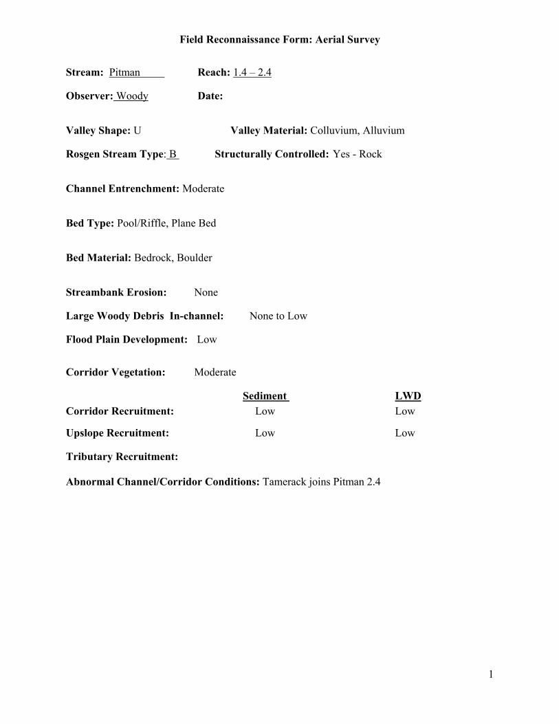
Field Reconnaissance Form: Aerial Survey
1
Stream: Pitman Reach: 1.4 – 2.4
Observer: Woody Date:
Valley Shape: U Valley Material: Colluvium, Alluvium
Rosgen Stream Type: B Structurally Controlled: Yes - Rock
Channel Entrenchment: Moderate
Bed Type: Pool/Riffle, Plane Bed
Bed Material: Bedrock, Boulder
Streambank Erosion: None
Large Woody Debris In-channel: None to Low
Flood Plain Development: Low
Corridor Vegetation: Moderate
Sediment LWDCorridor Recruitment: Low Low
Upslope Recruitment: Low Low
Tributary Recruitment:
Abnormal Channel/Corridor Conditions: Tamerack joins Pitman 2.4

Field Reconnaissance Form: Aerial Survey
2
Streambank Erosion
Bank Material: Bedrock, Boulder
StreambankVegetation Cover: 25-50%
Bank Erosion: 0-5%
Lateral Migration: No
Describe indicators for lateral migration:
Upslope Sediment Recruitment
Upslope Material: Bedrock, Forest soil
Upslope vegetation: Dense
Active Erosion: None
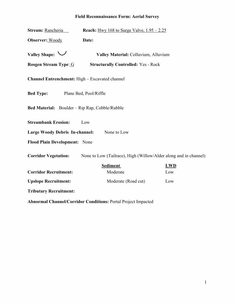
Field Reconnaissance Form: Aerial Survey
1
Stream: Rancheria Reach: Hwy 168 to Surge Valve, 1.95 – 2.25
Observer: Woody Date:
Valley Shape: Valley Material: Colluvium, Alluvium
Rosgen Stream Type: G Structurally Controlled: Yes - Rock
Channel Entrenchment: High – Excavated channel
Bed Type: Plane Bed, Pool/Riffle
Bed Material: Boulder – Rip Rap, Cobble/Rubble
Streambank Erosion: Low
Large Woody Debris In-channel: None to Low
Flood Plain Development: None
Corridor Vegetation: None to Low (Tailrace), High (Willow/Alder along and in channel)
Sediment LWDCorridor Recruitment: Moderate Low
Upslope Recruitment: Moderate (Road cut) Low
Tributary Recruitment:
Abnormal Channel/Corridor Conditions: Portal Project Impacted
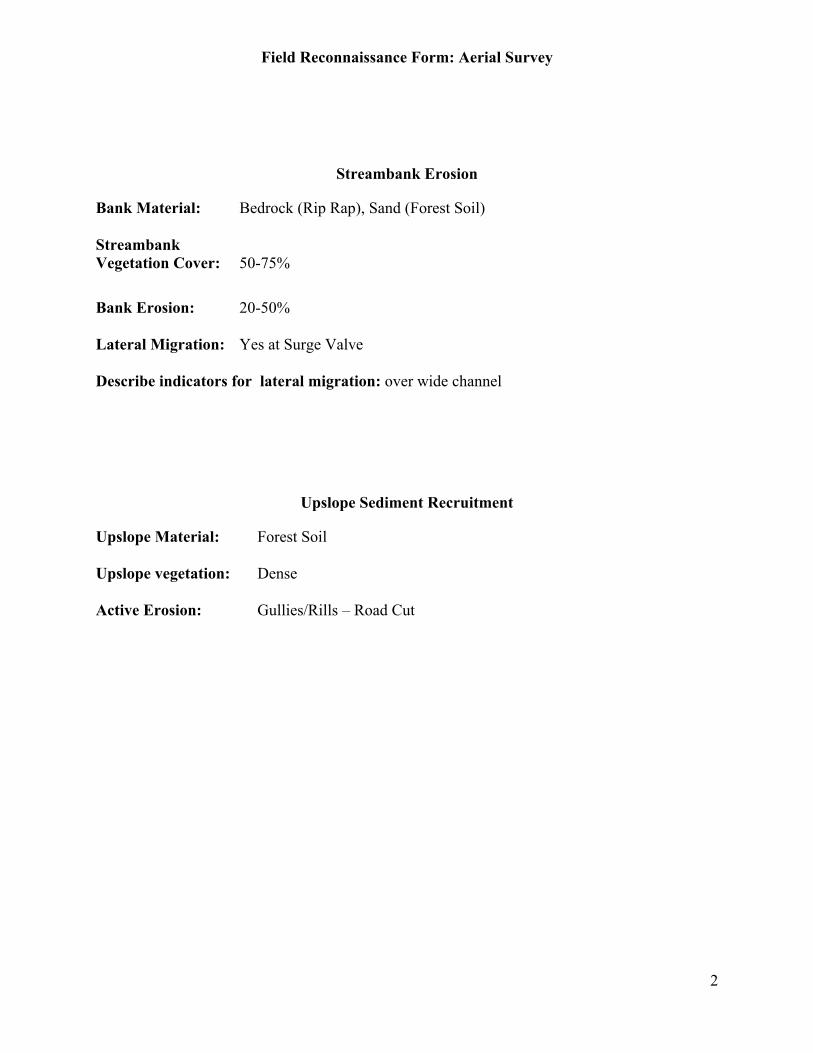
Field Reconnaissance Form: Aerial Survey
2
Streambank Erosion
Bank Material: Bedrock (Rip Rap), Sand (Forest Soil)
StreambankVegetation Cover: 50-75%
Bank Erosion: 20-50%
Lateral Migration: Yes at Surge Valve
Describe indicators for lateral migration: over wide channel
Upslope Sediment Recruitment
Upslope Material: Forest Soil
Upslope vegetation: Dense
Active Erosion: Gullies/Rills – Road Cut

Field Reconnaissance Form: Aerial Survey
1
Stream: Rancheria Reach: Above Surge Valve, 2.25 – 3.?
Observer: Woody Date: 7/16/2002
Valley Shape: Valley Material: Alluvium
Rosgen Stream Type: B2 Structurally Controlled: No
Channel Entrenchment: Moderate
Bed Type: Plane Bed, Pool/Riffle
Bed Material: Boulder, Cobble/Rubble
Streambank Erosion: Low
Large Woody Debris In-channel: None to Low
Flood Plain Development: Low
Corridor Vegetation: High
Sediment LWDCorridor Recruitment: Low Low
Upslope Recruitment: Low Low
Tributary Recruitment:
Abnormal Channel/Corridor Conditions: Great Looking Stream
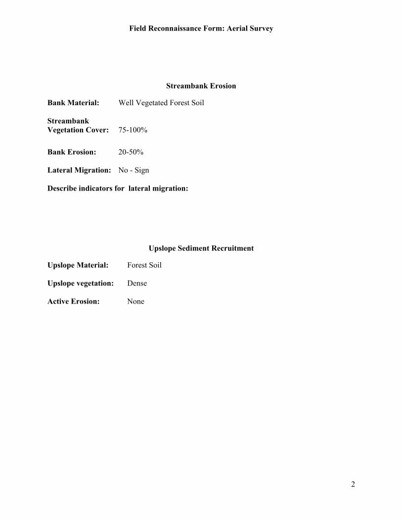
Field Reconnaissance Form: Aerial Survey
2
Streambank Erosion
Bank Material: Well Vegetated Forest Soil
StreambankVegetation Cover: 75-100%
Bank Erosion: 20-50%
Lateral Migration: No - Sign
Describe indicators for lateral migration:
Upslope Sediment Recruitment
Upslope Material: Forest Soil
Upslope vegetation: Dense
Active Erosion: None
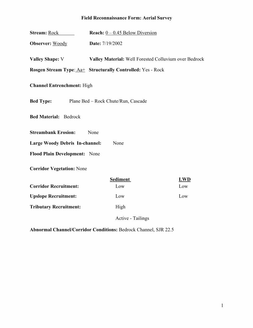
Field Reconnaissance Form: Aerial Survey
1
Stream: Rock Reach: 0 – 0.45 Below Diversion
Observer: Woody Date: 7/19/2002
Valley Shape: V Valley Material: Well Forested Colluvium over Bedrock
Rosgen Stream Type: Aa+ Structurally Controlled: Yes - Rock
Channel Entrenchment: High
Bed Type: Plane Bed – Rock Chute/Run, Cascade
Bed Material: Bedrock
Streambank Erosion: None
Large Woody Debris In-channel: None
Flood Plain Development: None
Corridor Vegetation: None
Sediment LWDCorridor Recruitment: Low Low
Upslope Recruitment: Low Low
Tributary Recruitment: High
Active - Tailings
Abnormal Channel/Corridor Conditions: Bedrock Channel, SJR 22.5

Field Reconnaissance Form: Aerial Survey
2
Streambank Erosion
Bank Material: Bedrock or Boulder
StreambankVegetation Cover: 0%
Bank Erosion: 0-5%
Lateral Migration: No
Describe indicators for lateral migration:
Upslope Sediment Recruitment
Upslope Material: Bedrock, Shallow Soil
Upslope vegetation: Scant
Active Erosion: None
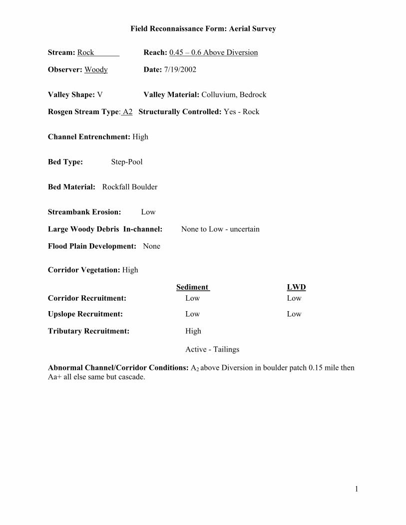
Field Reconnaissance Form: Aerial Survey
1
Stream: Rock Reach: 0.45 – 0.6 Above Diversion
Observer: Woody Date: 7/19/2002
Valley Shape: V Valley Material: Colluvium, Bedrock
Rosgen Stream Type: A2 Structurally Controlled: Yes - Rock
Channel Entrenchment: High
Bed Type: Step-Pool
Bed Material: Rockfall Boulder
Streambank Erosion: Low
Large Woody Debris In-channel: None to Low - uncertain
Flood Plain Development: None
Corridor Vegetation: High
Sediment LWDCorridor Recruitment: Low Low
Upslope Recruitment: Low Low
Tributary Recruitment: High
Active - Tailings
Abnormal Channel/Corridor Conditions: A2 above Diversion in boulder patch 0.15 mile thenAa+ all else same but cascade.
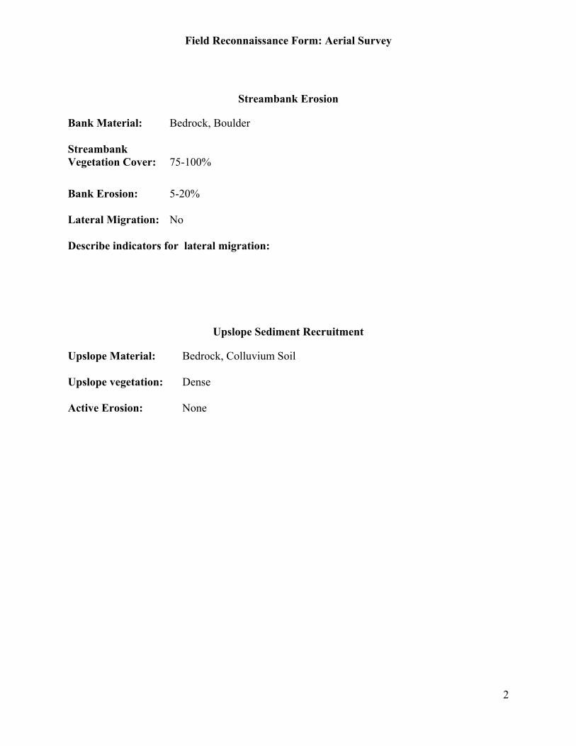
Field Reconnaissance Form: Aerial Survey
2
Streambank Erosion
Bank Material: Bedrock, Boulder
StreambankVegetation Cover: 75-100%
Bank Erosion: 5-20%
Lateral Migration: No
Describe indicators for lateral migration:
Upslope Sediment Recruitment
Upslope Material: Bedrock, Colluvium Soil
Upslope vegetation: Dense
Active Erosion: None

Field Reconnaissance Form: Aerial Survey
1
Stream: Ross Reach: Ross Below Diversion, 0 - 0.85
Observer: Woody Date: 7/19/2003
Valley Shape: V Valley Material: Bedrock, Shallow Colluvium
Rosgen Stream Type: Aa+ Structurally Controlled: Yes - Rock
Channel Entrenchment: High
Bed Type: Plane Bed – Chutes, Cascade
Bed Material: Bedrock, Some Boulder
Streambank Erosion: None
Large Woody Debris In-channel: None
Flood Plain Development: None
Corridor Vegetation: Low
Sediment LWDCorridor Recruitment: Low Low
Upslope Recruitment: Low Low
Tributary Recruitment:
Abnormal Channel/Corridor Conditions: SJR 18.7

Field Reconnaissance Form: Aerial Survey
2
Streambank Erosion
Bank Material: Bedrock or Boulder
StreambankVegetation Cover: 0-25%
Bank Erosion: 0-5%
Lateral Migration: No
Describe indicators for lateral migration:
Upslope Sediment Recruitment
Upslope Material: Bedrock, Colluvium Exposed
Upslope vegetation: Dense
Active Erosion: None
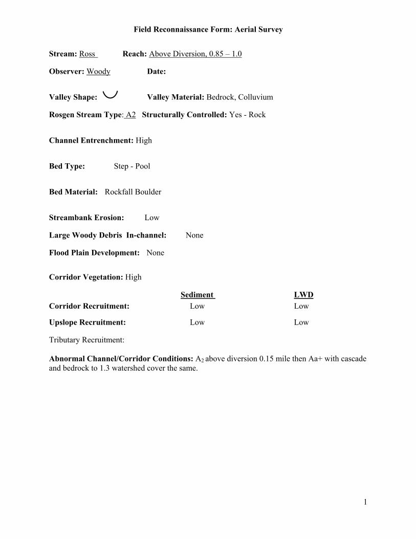
Field Reconnaissance Form: Aerial Survey
1
Stream: Ross Reach: Above Diversion, 0.85 – 1.0
Observer: Woody Date:
Valley Shape: Valley Material: Bedrock, Colluvium
Rosgen Stream Type: A2 Structurally Controlled: Yes - Rock
Channel Entrenchment: High
Bed Type: Step - Pool
Bed Material: Rockfall Boulder
Streambank Erosion: Low
Large Woody Debris In-channel: None
Flood Plain Development: None
Corridor Vegetation: High
Sediment LWDCorridor Recruitment: Low Low
Upslope Recruitment: Low Low
Tributary Recruitment:
Abnormal Channel/Corridor Conditions: A2 above diversion 0.15 mile then Aa+ with cascadeand bedrock to 1.3 watershed cover the same.

Field Reconnaissance Form: Aerial Survey
2
Streambank Erosion
Bank Material: Bedrock
StreambankVegetation Cover: 75-100%
Bank Erosion: 5-20%
Lateral Migration: No
Describe indicators for lateral migration:
Upslope Sediment Recruitment
Upslope Material: Bedrock, Forested Soil
Upslope vegetation: Dense
Active Erosion: None
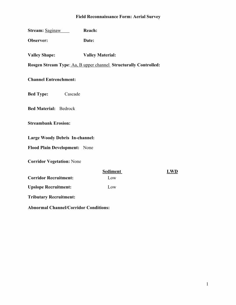
Field Reconnaissance Form: Aerial Survey
1
Stream: Saginaw Reach:
Observer: Date:
Valley Shape: Valley Material:
Rosgen Stream Type: Aa, B upper channel Structurally Controlled:
Channel Entrenchment:
Bed Type: Cascade
Bed Material: Bedrock
Streambank Erosion:
Large Woody Debris In-channel:
Flood Plain Development: None
Corridor Vegetation: None
Sediment LWDCorridor Recruitment: Low
Upslope Recruitment: Low
Tributary Recruitment:
Abnormal Channel/Corridor Conditions:

Field Reconnaissance Form: Aerial Survey
2
Streambank Erosion
Bank Material:StreambankVegetation Cover:
Bank Erosion:
Lateral Migration:
Describe indicators for lateral migration:
Upslope Sediment Recruitment
Upslope Material:
Upslope vegetation:
Active Erosion: None
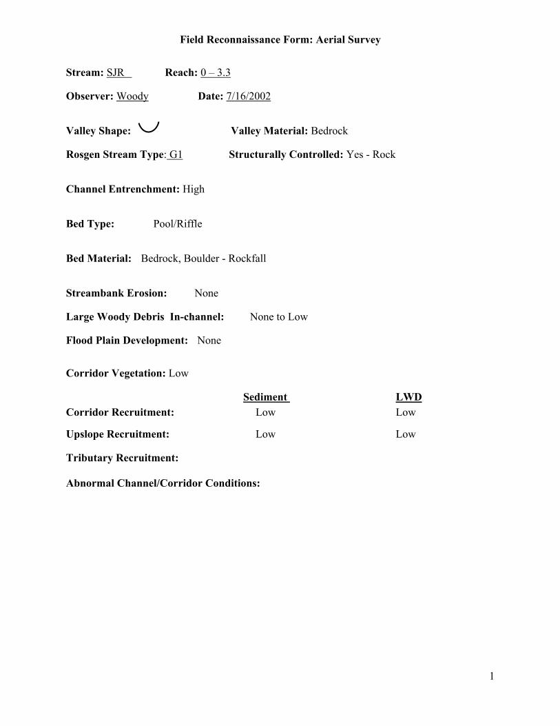
Field Reconnaissance Form: Aerial Survey
1
Stream: SJR Reach: 0 – 3.3
Observer: Woody Date: 7/16/2002
Valley Shape: Valley Material: Bedrock
Rosgen Stream Type: G1 Structurally Controlled: Yes - Rock
Channel Entrenchment: High
Bed Type: Pool/Riffle
Bed Material: Bedrock, Boulder - Rockfall
Streambank Erosion: None
Large Woody Debris In-channel: None to Low
Flood Plain Development: None
Corridor Vegetation: Low
Sediment LWDCorridor Recruitment: Low Low
Upslope Recruitment: Low Low
Tributary Recruitment:
Abnormal Channel/Corridor Conditions:

Field Reconnaissance Form: Aerial Survey
2
Streambank Erosion
Bank Material: Bedrock
StreambankVegetation Cover: 0-25%
Bank Erosion: 0-5%
Lateral Migration: No
Describe indicators for lateral migration:
Upslope Sediment Recruitment
Upslope Material: Bedrock
Upslope vegetation: Scant
Active Erosion: None

Field Reconnaissance Form: Aerial Survey
1
Stream: SJR Reach: 3.3 – 5.6, Below Willow Creek
Observer: Woody Date: 7/16/2002
Valley Shape: U Valley Material: Bedrock
Rosgen Stream Type: G1 Structurally Controlled: Rock
Channel Entrenchment: High
Bed Type: Pool/Riffle, Plane Bed – Long Runs
Bed Material: Cobble/Rubble, Sand
Streambank Erosion: None
Large Woody Debris In-channel: None to Low
Flood Plain Development: None
Corridor Vegetation: None, Moderate (below Willow Creek)
Sediment LWDCorridor Recruitment: Low Low
Upslope Recruitment: Low Low
Tributary Recruitment: Moderate – Willow CreekActive
Abnormal Channel/Corridor Conditions: Sand and Willows below Willow Creek in channel.Habitat no geomorph in flume.

Field Reconnaissance Form: Aerial Survey
2
Streambank Erosion
Bank Material: Bedrock
StreambankVegetation Cover: 0-25%
Bank Erosion: 0-5%
Lateral Migration: No
Describe indicators for lateral migration:
Upslope Sediment Recruitment
Upslope Material: Bedrock, shallow soil
Upslope vegetation: Scant
Active Erosion: None

Field Reconnaissance Form: Aerial Survey
1
Stream: SJR Reach: 5.6 – 6.1, Below Redinger Dam
Observer: Woody Date:
Valley Shape: U Valley Material: Bedrock
Rosgen Stream Type: G1 Structurally Controlled: Yes - Rock
Channel Entrenchment: High
Bed Type: Pool/Riffle, Plane Bed
Bed Material: Bedrock, Boulder
Streambank Erosion: None
Large Woody Debris In-channel: None to Low
Flood Plain Development: None
Corridor Vegetation: Low
Sediment LWDCorridor Recruitment: Low Low
Upslope Recruitment: Low Low
Tributary Recruitment:
Abnormal Channel/Corridor Conditions: Redinger Dam at 6.1
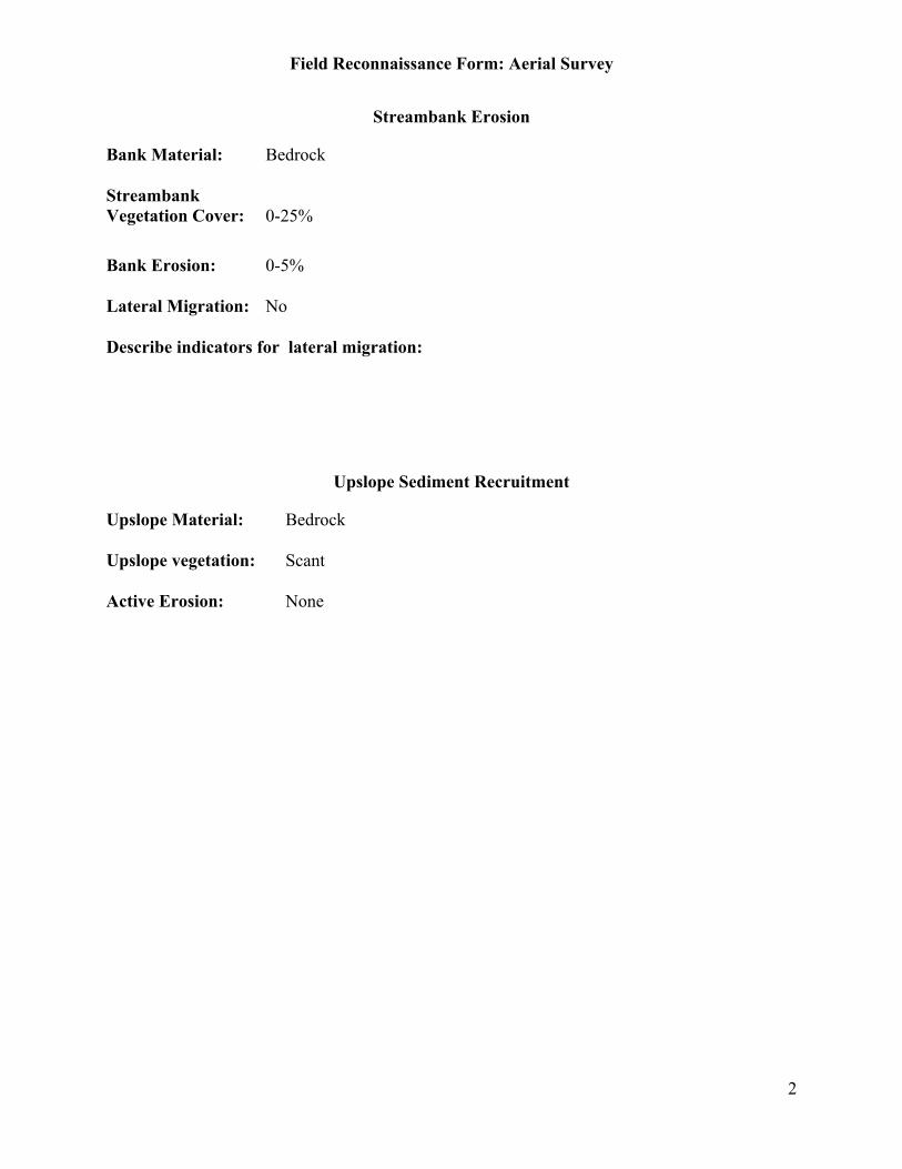
Field Reconnaissance Form: Aerial Survey
2
Streambank Erosion
Bank Material: Bedrock
StreambankVegetation Cover: 0-25%
Bank Erosion: 0-5%
Lateral Migration: No
Describe indicators for lateral migration:
Upslope Sediment Recruitment
Upslope Material: Bedrock
Upslope vegetation: Scant
Active Erosion: None
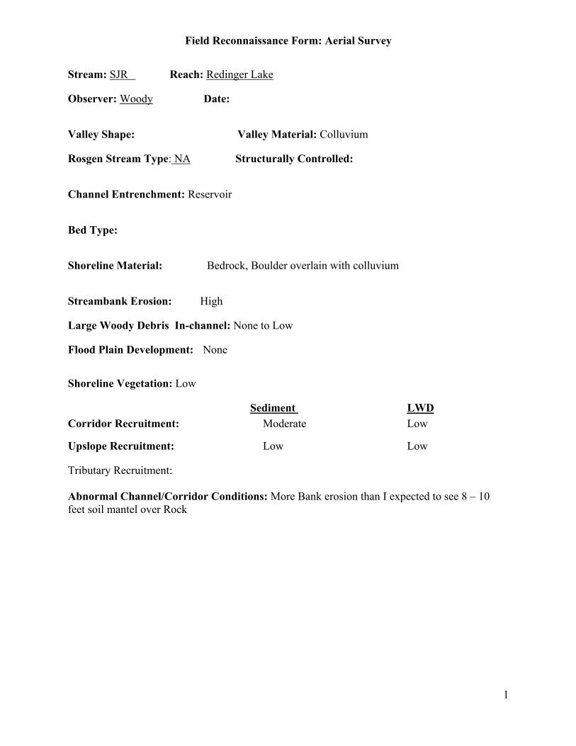
Field Reconnaissance Form: Aerial Survey
1
Stream: SJR Reach: Redinger Lake
Observer: Woody Date:
Valley Shape: Valley Material: Colluvium
Rosgen Stream Type: NA Structurally Controlled:
Channel Entrenchment: Reservoir
Bed Type:
Shoreline Material: Bedrock, Boulder overlain with colluvium
Streambank Erosion: High
Large Woody Debris In-channel: None to Low
Flood Plain Development: None
Shoreline Vegetation: Low
Sediment LWDCorridor Recruitment: Moderate Low
Upslope Recruitment: Low Low
Tributary Recruitment:
Abnormal Channel/Corridor Conditions: More Bank erosion than I expected to see 8 – 10feet soil mantel over Rock

Field Reconnaissance Form: Aerial Survey
2
Shoreline Erosion
Bank Material: Bedrock, Boulder with deep Colluvium
StreambankVegetation Cover:
Bank Erosion:
Lateral Migration:
Describe indicators for lateral migration:
Upslope Sediment Recruitment
Upslope Material: Bedrock, Colluvium
Upslope vegetation: Scant to Moderate
Active Erosion: None

Field Reconnaissance Form: Aerial Survey
1
Stream: SJR Reach: Head Redinger to Power House 3
Observer: Woody Date:
Valley Shape: Valley Material:
Rosgen Stream Type: G2 Structurally Controlled: Yes - Rock
Channel Entrenchment: High
Bed Type: Pool/Riffle, Plane Bed
Bed Material: Boulder, Cobble/Rubble
Streambank Erosion: None
Large Woody Debris In-channel: None to Low
Flood Plain Development: None
Corridor Vegetation: Low
Sediment LWDCorridor Recruitment: Low Low
Upslope Recruitment: Low Low
Tributary Recruitment:
Abnormal Channel/Corridor Conditions:

Field Reconnaissance Form: Aerial Survey
2
Streambank Erosion
Bank Material: Bedrock
StreambankVegetation Cover: 0-25%
Bank Erosion: 0-5%
Lateral Migration: No
Describe indicators for lateral migration:
Upslope Sediment Recruitment
Upslope Material: Bedrock, Soil
Upslope vegetation: Scant
Active Erosion: None
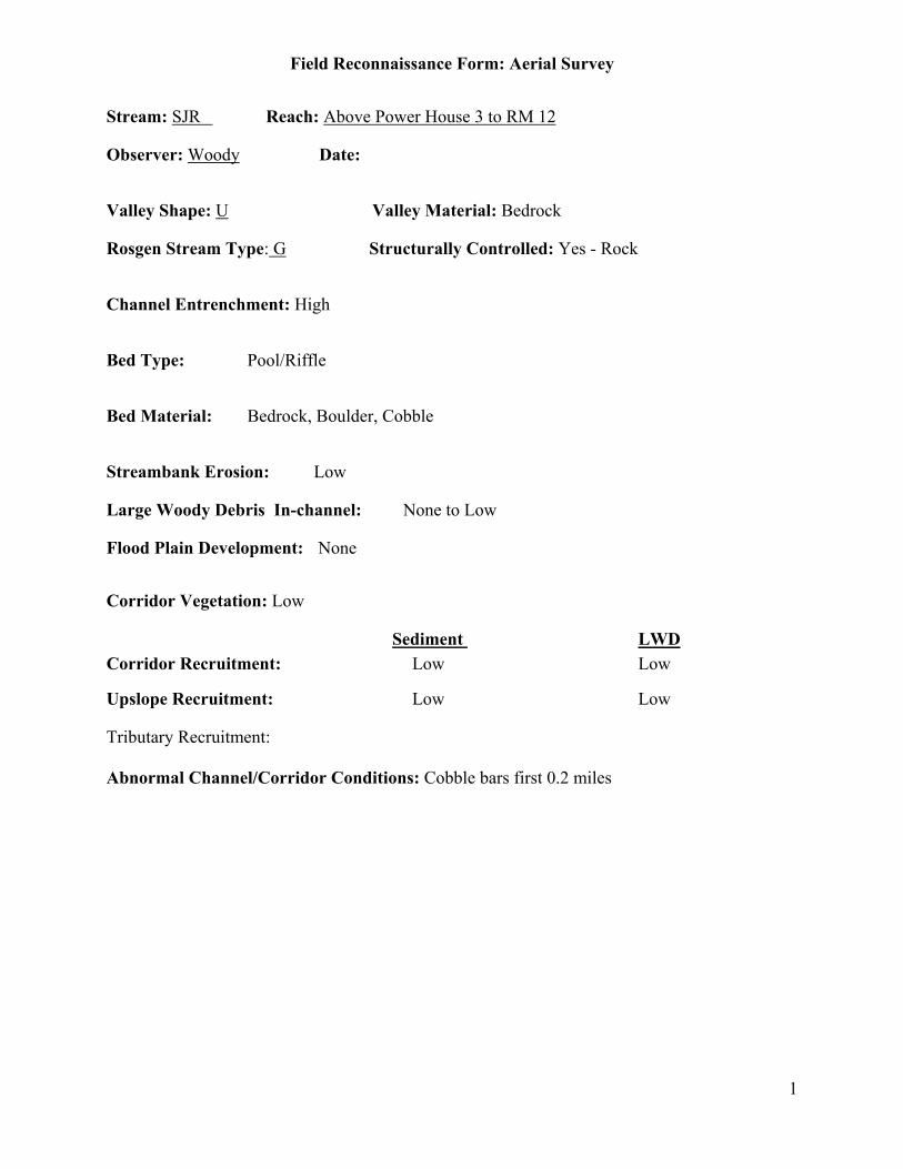
Field Reconnaissance Form: Aerial Survey
1
Stream: SJR Reach: Above Power House 3 to RM 12
Observer: Woody Date:
Valley Shape: U Valley Material: Bedrock
Rosgen Stream Type: G Structurally Controlled: Yes - Rock
Channel Entrenchment: High
Bed Type: Pool/Riffle
Bed Material: Bedrock, Boulder, Cobble
Streambank Erosion: Low
Large Woody Debris In-channel: None to Low
Flood Plain Development: None
Corridor Vegetation: Low
Sediment LWDCorridor Recruitment: Low Low
Upslope Recruitment: Low Low
Tributary Recruitment:
Abnormal Channel/Corridor Conditions: Cobble bars first 0.2 miles

Field Reconnaissance Form: Aerial Survey
2
Streambank Erosion
Bank Material: Bedrock
StreambankVegetation Cover: 0-25%
Bank Erosion: 0-5%
Lateral Migration: No
Describe indicators for lateral migration:
Upslope Sediment Recruitment
Upslope Material: Bedrock – Shallow Soils
Upslope vegetation: Scant
Active Erosion: None
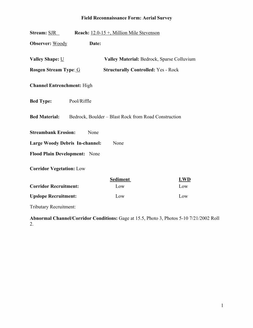
Field Reconnaissance Form: Aerial Survey
1
Stream: SJR Reach: 12.0-15 +, Million Mile Stevenson
Observer: Woody Date:
Valley Shape: U Valley Material: Bedrock, Sparse Colluvium
Rosgen Stream Type: G Structurally Controlled: Yes - Rock
Channel Entrenchment: High
Bed Type: Pool/Riffle
Bed Material: Bedrock, Boulder – Blast Rock from Road Construction
Streambank Erosion: None
Large Woody Debris In-channel: None
Flood Plain Development: None
Corridor Vegetation: Low
Sediment LWDCorridor Recruitment: Low Low
Upslope Recruitment: Low Low
Tributary Recruitment:
Abnormal Channel/Corridor Conditions: Gage at 15.5, Photo 3, Photos 5-10 7/21/2002 Roll2.
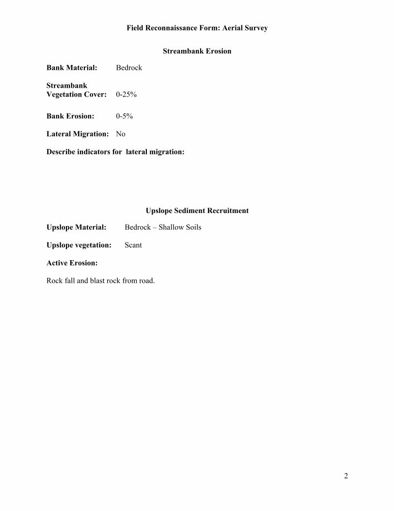
Field Reconnaissance Form: Aerial Survey
2
Streambank Erosion
Bank Material: Bedrock
StreambankVegetation Cover: 0-25%
Bank Erosion: 0-5%
Lateral Migration: No
Describe indicators for lateral migration:
Upslope Sediment Recruitment
Upslope Material: Bedrock – Shallow Soils
Upslope vegetation: Scant
Active Erosion:
Rock fall and blast rock from road.
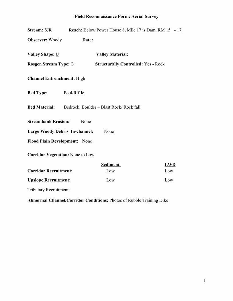
Field Reconnaissance Form: Aerial Survey
1
Stream: SJR Reach: Below Power House 8, Mile 17 is Dam, RM 15+ - 17
Observer: Woody Date:
Valley Shape: U Valley Material:
Rosgen Stream Type: G Structurally Controlled: Yes - Rock
Channel Entrenchment: High
Bed Type: Pool/Riffle
Bed Material: Bedrock, Boulder – Blast Rock/ Rock fall
Streambank Erosion: None
Large Woody Debris In-channel: None
Flood Plain Development: None
Corridor Vegetation: None to Low
Sediment LWDCorridor Recruitment: Low Low
Upslope Recruitment: Low Low
Tributary Recruitment:
Abnormal Channel/Corridor Conditions: Photos of Rubble Training Dike

Field Reconnaissance Form: Aerial Survey
2
Streambank Erosion
Bank Material: Bedrock
StreambankVegetation Cover: 0-25%
Bank Erosion: 0-5%
Lateral Migration: No
Describe indicators for lateral migration:
Upslope Sediment Recruitment
Upslope Material: Bedrock – Shallow Soils
Upslope vegetation: Scant
Active Erosion: None
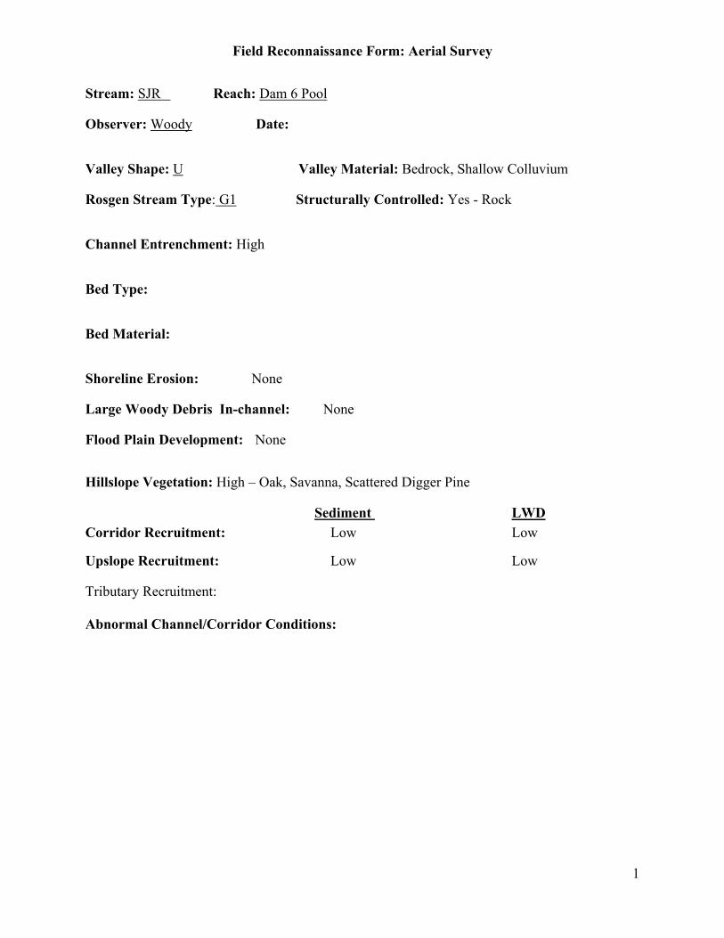
Field Reconnaissance Form: Aerial Survey
1
Stream: SJR Reach: Dam 6 Pool
Observer: Woody Date:
Valley Shape: U Valley Material: Bedrock, Shallow Colluvium
Rosgen Stream Type: G1 Structurally Controlled: Yes - Rock
Channel Entrenchment: High
Bed Type:
Bed Material:
Shoreline Erosion: None
Large Woody Debris In-channel: None
Flood Plain Development: None
Hillslope Vegetation: High – Oak, Savanna, Scattered Digger Pine
Sediment LWDCorridor Recruitment: Low Low
Upslope Recruitment: Low Low
Tributary Recruitment:
Abnormal Channel/Corridor Conditions:
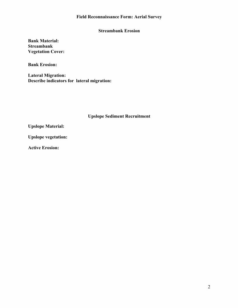
Field Reconnaissance Form: Aerial Survey
2
Streambank Erosion
Bank Material:StreambankVegetation Cover:
Bank Erosion:
Lateral Migration:Describe indicators for lateral migration:
Upslope Sediment Recruitment
Upslope Material:
Upslope vegetation:
Active Erosion:
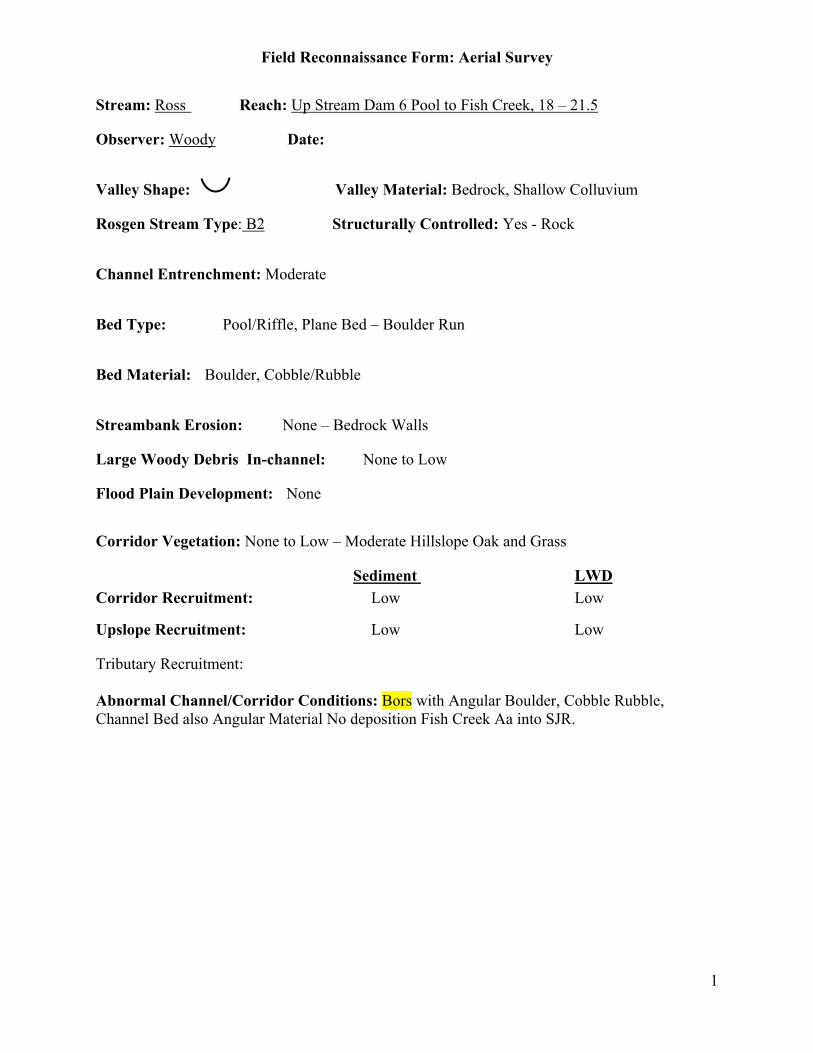
Field Reconnaissance Form: Aerial Survey
1
Stream: Ross Reach: Up Stream Dam 6 Pool to Fish Creek, 18 – 21.5
Observer: Woody Date:
Valley Shape: Valley Material: Bedrock, Shallow Colluvium
Rosgen Stream Type: B2 Structurally Controlled: Yes - Rock
Channel Entrenchment: Moderate
Bed Type: Pool/Riffle, Plane Bed – Boulder Run
Bed Material: Boulder, Cobble/Rubble
Streambank Erosion: None – Bedrock Walls
Large Woody Debris In-channel: None to Low
Flood Plain Development: None
Corridor Vegetation: None to Low – Moderate Hillslope Oak and Grass
Sediment LWDCorridor Recruitment: Low Low
Upslope Recruitment: Low Low
Tributary Recruitment:
Abnormal Channel/Corridor Conditions: Bors with Angular Boulder, Cobble Rubble,Channel Bed also Angular Material No deposition Fish Creek Aa into SJR.
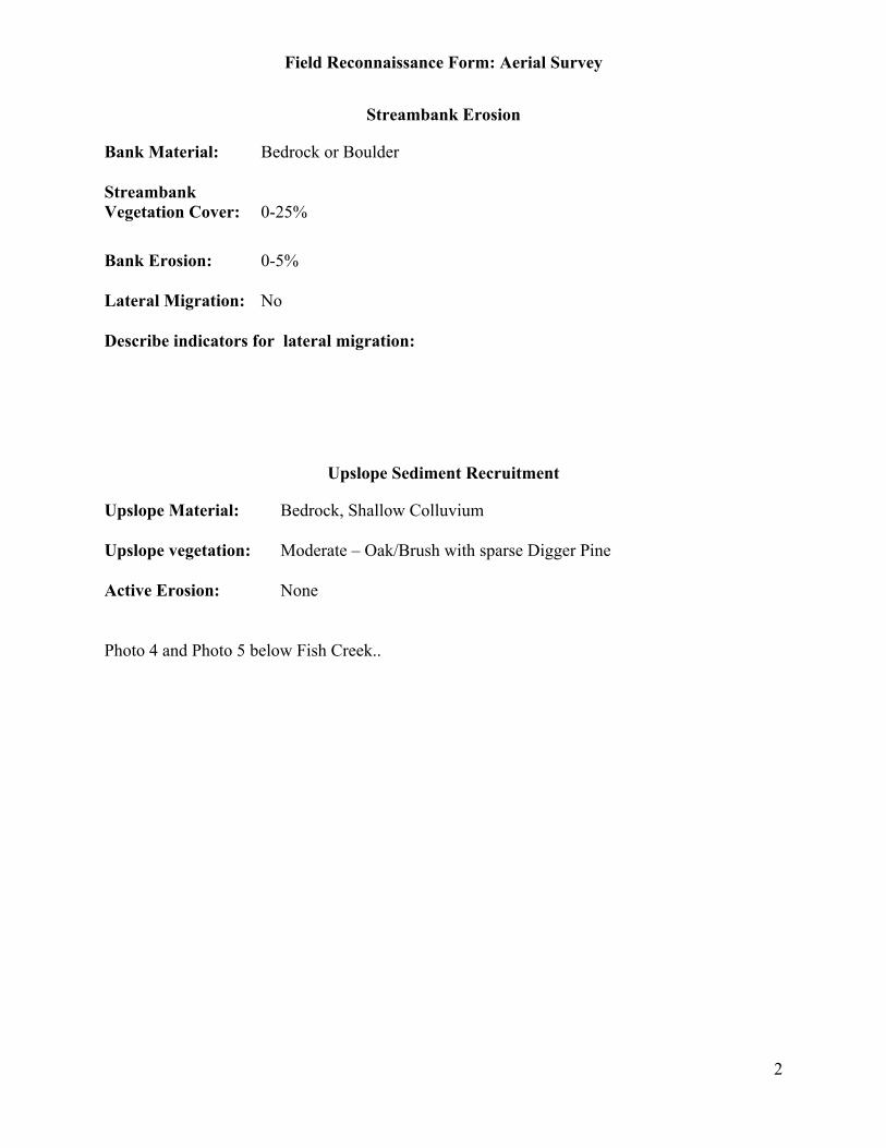
Field Reconnaissance Form: Aerial Survey
2
Streambank Erosion
Bank Material: Bedrock or Boulder
StreambankVegetation Cover: 0-25%
Bank Erosion: 0-5%
Lateral Migration: No
Describe indicators for lateral migration:
Upslope Sediment Recruitment
Upslope Material: Bedrock, Shallow Colluvium
Upslope vegetation: Moderate – Oak/Brush with sparse Digger Pine
Active Erosion: None
Photo 4 and Photo 5 below Fish Creek..
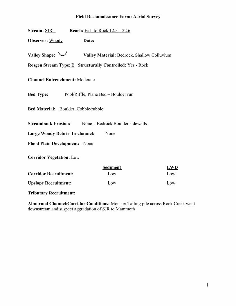
Field Reconnaissance Form: Aerial Survey
1
Stream: SJR Reach: Fish to Rock 12.5 – 22.6
Observer: Woody Date:
Valley Shape: Valley Material: Bedrock, Shallow Colluvium
Rosgen Stream Type: B Structurally Controlled: Yes - Rock
Channel Entrenchment: Moderate
Bed Type: Pool/Riffle, Plane Bed – Boulder run
Bed Material: Boulder, Cobble/rubble
Streambank Erosion: None – Bedrock Boulder sidewalls
Large Woody Debris In-channel: None
Flood Plain Development: None
Corridor Vegetation: Low
Sediment LWDCorridor Recruitment: Low Low
Upslope Recruitment: Low Low
Tributary Recruitment:
Abnormal Channel/Corridor Conditions: Monster Tailing pile across Rock Creek wentdownstream and suspect aggradation of SJR to Mammoth

Field Reconnaissance Form: Aerial Survey
2
Streambank Erosion
Bank Material: Bedrock or Boulder
StreambankVegetation Cover: 0-25%
Bank Erosion: 0-5%
Lateral Migration: No
Describe indicators for lateral migration:
Upslope Sediment Recruitment
Upslope Material: Bedrock, Shallow Forested Soil
Upslope vegetation: Dense
Active Erosion: None
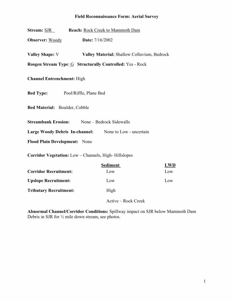
Field Reconnaissance Form: Aerial Survey
1
Stream: SJR Reach: Rock Creek to Mammoth Dam
Observer: Woody Date: 7/16/2002
Valley Shape: V Valley Material: Shallow Colluvium, Bedrock
Rosgen Stream Type: G Structurally Controlled: Yes - Rock
Channel Entrenchment: High
Bed Type: Pool/Riffle, Plane Bed
Bed Material: Boulder, Cobble
Streambank Erosion: None – Bedrock Sidewalls
Large Woody Debris In-channel: None to Low - uncertain
Flood Plain Development: None
Corridor Vegetation: Low – Channels, High- Hillslopes
Sediment LWDCorridor Recruitment: Low Low
Upslope Recruitment: Low Low
Tributary Recruitment: High
Active – Rock Creek
Abnormal Channel/Corridor Conditions: Spillway impact on SJR below Mammoth DamDebris in SJR for ½ mile down stream, see photos.

Field Reconnaissance Form: Aerial Survey
2
Streambank Erosion
Bank Material: Bedrock, Boulder
StreambankVegetation Cover: 0-25%
Bank Erosion: 0-5%
Lateral Migration: No
Describe indicators for lateral migration:
Upslope Sediment Recruitment
Upslope Material: Bedrock, Exposed Colluvium Soil
Upslope vegetation: Dense
Active Erosion: Landslides
Hillside 1 to 2 Mile above Rock Creek

Mammoth Pool
Bank Erosion Much less then reported - only significant shoreline erosion is in vicinity
of campground. 90% or so of shoreline is non-erodible.
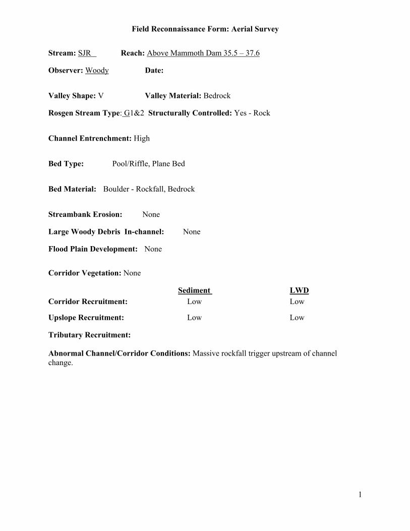
Field Reconnaissance Form: Aerial Survey
1
Stream: SJR Reach: Above Mammoth Dam 35.5 – 37.6
Observer: Woody Date:
Valley Shape: V Valley Material: Bedrock
Rosgen Stream Type: G1&2 Structurally Controlled: Yes - Rock
Channel Entrenchment: High
Bed Type: Pool/Riffle, Plane Bed
Bed Material: Boulder - Rockfall, Bedrock
Streambank Erosion: None
Large Woody Debris In-channel: None
Flood Plain Development: None
Corridor Vegetation: None
Sediment LWDCorridor Recruitment: Low Low
Upslope Recruitment: Low Low
Tributary Recruitment:
Abnormal Channel/Corridor Conditions: Massive rockfall trigger upstream of channelchange.
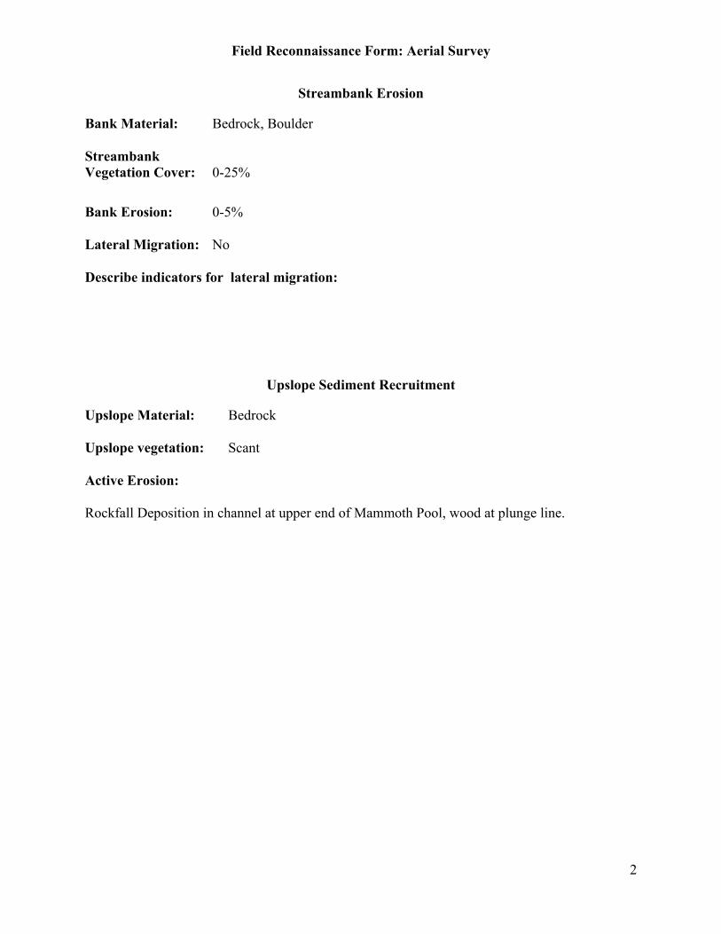
Field Reconnaissance Form: Aerial Survey
2
Streambank Erosion
Bank Material: Bedrock, Boulder
StreambankVegetation Cover: 0-25%
Bank Erosion: 0-5%
Lateral Migration: No
Describe indicators for lateral migration:
Upslope Sediment Recruitment
Upslope Material: Bedrock
Upslope vegetation: Scant
Active Erosion:
Rockfall Deposition in channel at upper end of Mammoth Pool, wood at plunge line.
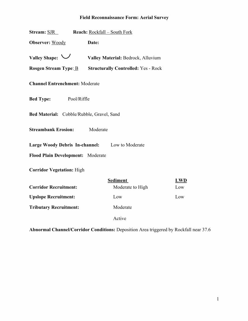
Field Reconnaissance Form: Aerial Survey
1
Stream: SJR Reach: Rockfall – South Fork
Observer: Woody Date:
Valley Shape: Valley Material: Bedrock, Alluvium
Rosgen Stream Type: B Structurally Controlled: Yes - Rock
Channel Entrenchment: Moderate
Bed Type: Pool/Riffle
Bed Material: Cobble/Rubble, Gravel, Sand
Streambank Erosion: Moderate
Large Woody Debris In-channel: Low to Moderate
Flood Plain Development: Moderate
Corridor Vegetation: High
Sediment LWDCorridor Recruitment: Moderate to High Low
Upslope Recruitment: Low Low
Tributary Recruitment: Moderate
Active
Abnormal Channel/Corridor Conditions: Deposition Area triggered by Rockfall near 37.6
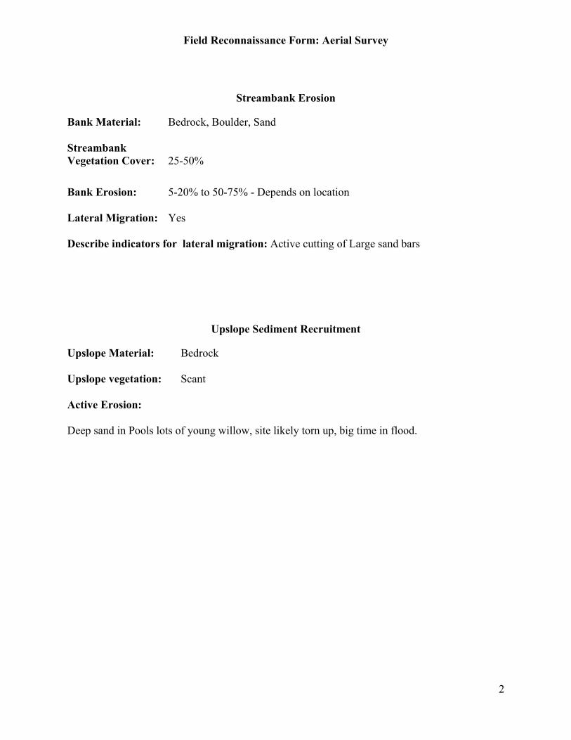
Field Reconnaissance Form: Aerial Survey
2
Streambank Erosion
Bank Material: Bedrock, Boulder, Sand
StreambankVegetation Cover: 25-50%
Bank Erosion: 5-20% to 50-75% - Depends on location
Lateral Migration: Yes
Describe indicators for lateral migration: Active cutting of Large sand bars
Upslope Sediment Recruitment
Upslope Material: Bedrock
Upslope vegetation: Scant
Active Erosion:
Deep sand in Pools lots of young willow, site likely torn up, big time in flood.
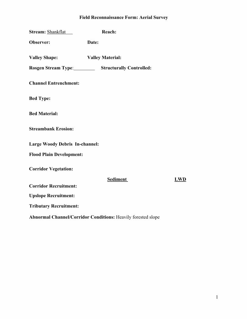
Field Reconnaissance Form: Aerial Survey
1
Stream: Shankflat Reach:
Observer: Date:
Valley Shape: Valley Material:
Rosgen Stream Type: Structurally Controlled:
Channel Entrenchment:
Bed Type:
Bed Material:
Streambank Erosion:
Large Woody Debris In-channel:
Flood Plain Development:
Corridor Vegetation:
Sediment LWDCorridor Recruitment:
Upslope Recruitment:
Tributary Recruitment:
Abnormal Channel/Corridor Conditions: Heavily forested slope

Field Reconnaissance Form: Aerial Survey
2
Streambank Erosion
Bank Material:StreambankVegetation Cover:
Bank Erosion:
Lateral Migration:
Describe indicators for lateral migration:
Upslope Sediment Recruitment
Upslope Material:
Upslope vegetation:
Active Erosion:
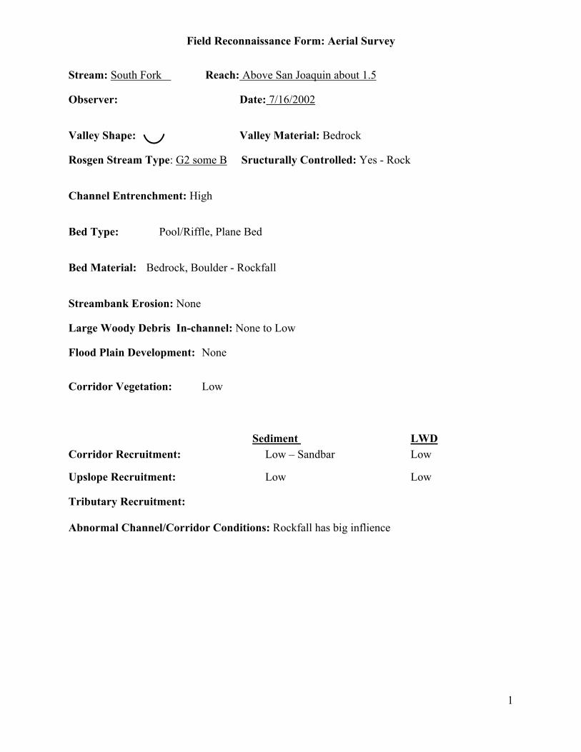
Field Reconnaissance Form: Aerial Survey
1
Stream: South Fork Reach: Above San Joaquin about 1.5
Observer: Date: 7/16/2002
Valley Shape: Valley Material: Bedrock
Rosgen Stream Type: G2 some B Sructurally Controlled: Yes - Rock
Channel Entrenchment: High
Bed Type: Pool/Riffle, Plane Bed
Bed Material: Bedrock, Boulder - Rockfall
Streambank Erosion: None
Large Woody Debris In-channel: None to Low
Flood Plain Development: None
Corridor Vegetation: Low
Sediment LWDCorridor Recruitment: Low – Sandbar Low
Upslope Recruitment: Low Low
Tributary Recruitment:
Abnormal Channel/Corridor Conditions: Rockfall has big inflience
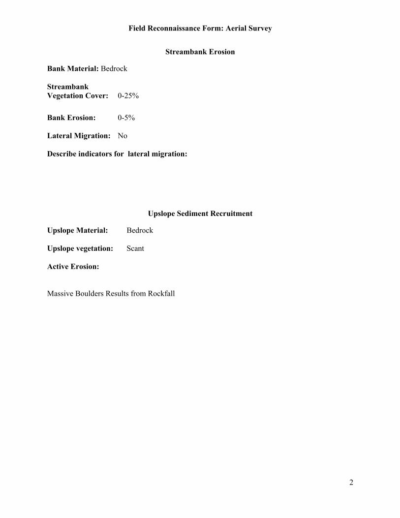
Field Reconnaissance Form: Aerial Survey
2
Streambank Erosion
Bank Material: Bedrock
StreambankVegetation Cover: 0-25%
Bank Erosion: 0-5%
Lateral Migration: No
Describe indicators for lateral migration:
Upslope Sediment Recruitment
Upslope Material: Bedrock
Upslope vegetation: Scant
Active Erosion:
Massive Boulders Results from Rockfall
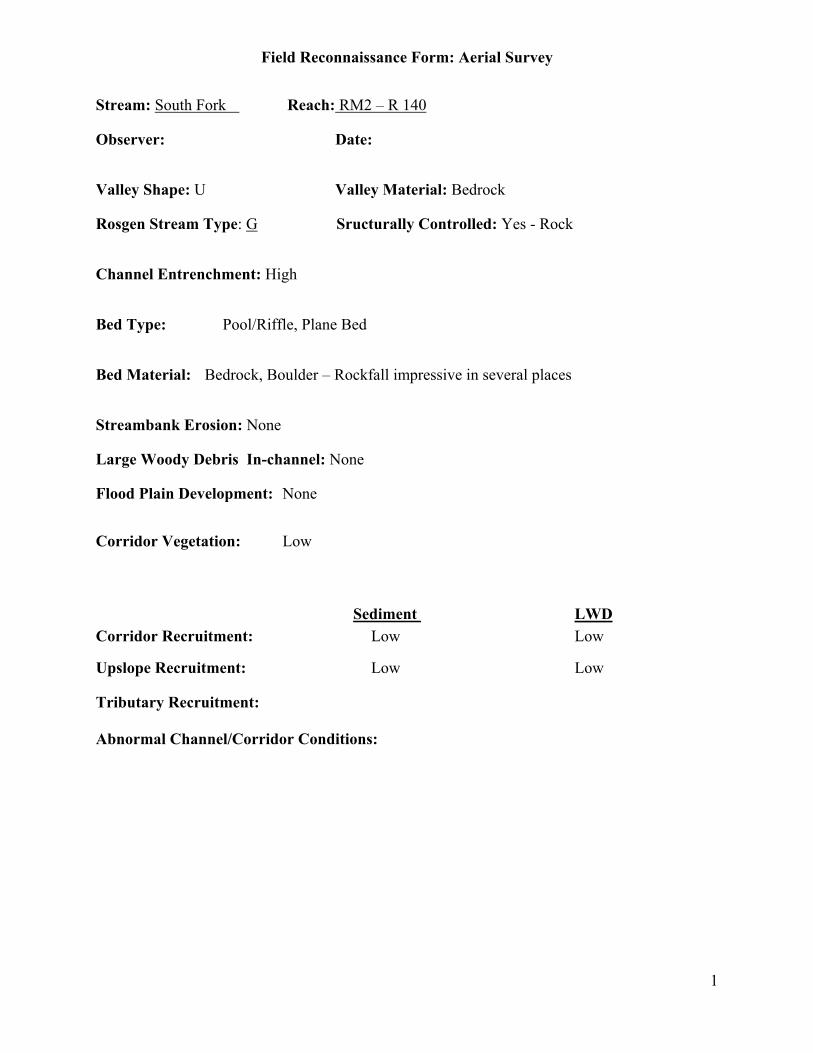
Field Reconnaissance Form: Aerial Survey
1
Stream: South Fork Reach: RM2 – R 140
Observer: Date:
Valley Shape: U Valley Material: Bedrock
Rosgen Stream Type: G Sructurally Controlled: Yes - Rock
Channel Entrenchment: High
Bed Type: Pool/Riffle, Plane Bed
Bed Material: Bedrock, Boulder – Rockfall impressive in several places
Streambank Erosion: None
Large Woody Debris In-channel: None
Flood Plain Development: None
Corridor Vegetation: Low
Sediment LWDCorridor Recruitment: Low Low
Upslope Recruitment: Low Low
Tributary Recruitment:
Abnormal Channel/Corridor Conditions:

Field Reconnaissance Form: Aerial Survey
2
Streambank Erosion
Bank Material: Bedrock
StreambankVegetation Cover: 0-25%
Bank Erosion: 0-5%
Lateral Migration: No
Describe indicators for lateral migration:
Upslope Sediment Recruitment
Upslope Material: Bedrock, Exposed Soil
Upslope vegetation: Scant
Active Erosion:
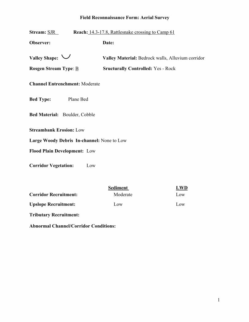
Field Reconnaissance Form: Aerial Survey
1
Stream: SJR Reach: 14.3-17.8, Rattlesnake crossing to Camp 61
Observer: Date:
Valley Shape: Valley Material: Bedrock walls, Alluvium corridor
Rosgen Stream Type: B Sructurally Controlled: Yes - Rock
Channel Entrenchment: Moderate
Bed Type: Plane Bed
Bed Material: Boulder, Cobble
Streambank Erosion: Low
Large Woody Debris In-channel: None to Low
Flood Plain Development: Low
Corridor Vegetation: Low
Sediment LWDCorridor Recruitment: Moderate Low
Upslope Recruitment: Low Low
Tributary Recruitment:
Abnormal Channel/Corridor Conditions:

Field Reconnaissance Form: Aerial Survey
2
Streambank Erosion
Bank Material: Bedrock, Boulder, Cobble/Gravel
StreambankVegetation Cover: 25-50%
Bank Erosion: 5-20%
Lateral Migration: No
Describe indicators for lateral migration:
Upslope Sediment Recruitment
Upslope Material: Bedrock, Exposed Soil
Upslope vegetation: Scant
Active Erosion: None
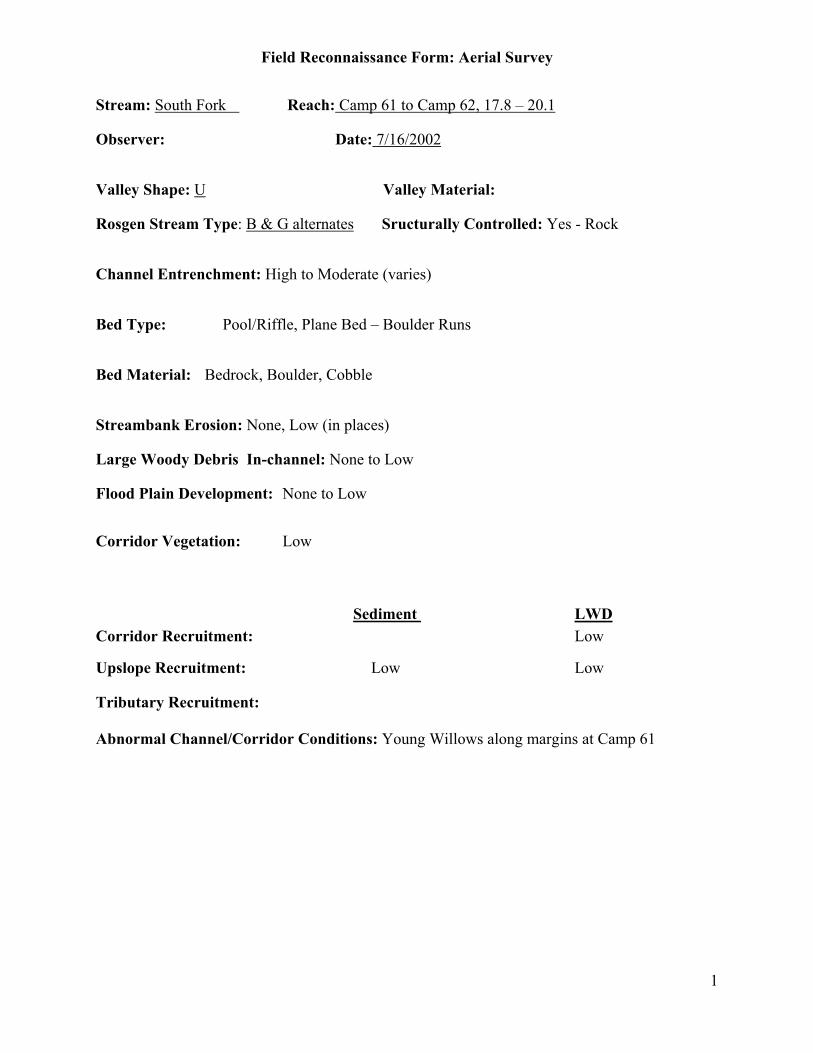
Field Reconnaissance Form: Aerial Survey
1
Stream: South Fork Reach: Camp 61 to Camp 62, 17.8 – 20.1
Observer: Date: 7/16/2002
Valley Shape: U Valley Material:
Rosgen Stream Type: B & G alternates Sructurally Controlled: Yes - Rock
Channel Entrenchment: High to Moderate (varies)
Bed Type: Pool/Riffle, Plane Bed – Boulder Runs
Bed Material: Bedrock, Boulder, Cobble
Streambank Erosion: None, Low (in places)
Large Woody Debris In-channel: None to Low
Flood Plain Development: None to Low
Corridor Vegetation: Low
Sediment LWDCorridor Recruitment: Low
Upslope Recruitment: Low Low
Tributary Recruitment:
Abnormal Channel/Corridor Conditions: Young Willows along margins at Camp 61
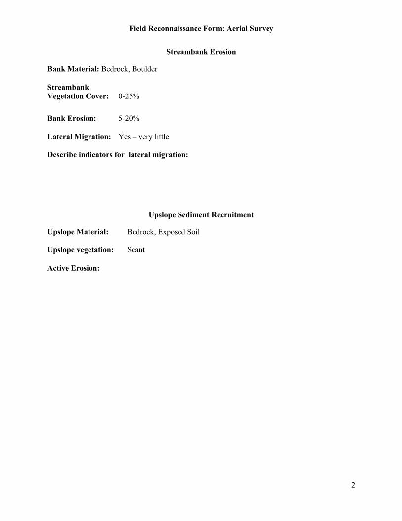
Field Reconnaissance Form: Aerial Survey
2
Streambank Erosion
Bank Material: Bedrock, Boulder
StreambankVegetation Cover: 0-25%
Bank Erosion: 5-20%
Lateral Migration: Yes – very little
Describe indicators for lateral migration:
Upslope Sediment Recruitment
Upslope Material: Bedrock, Exposed Soil
Upslope vegetation: Scant
Active Erosion:
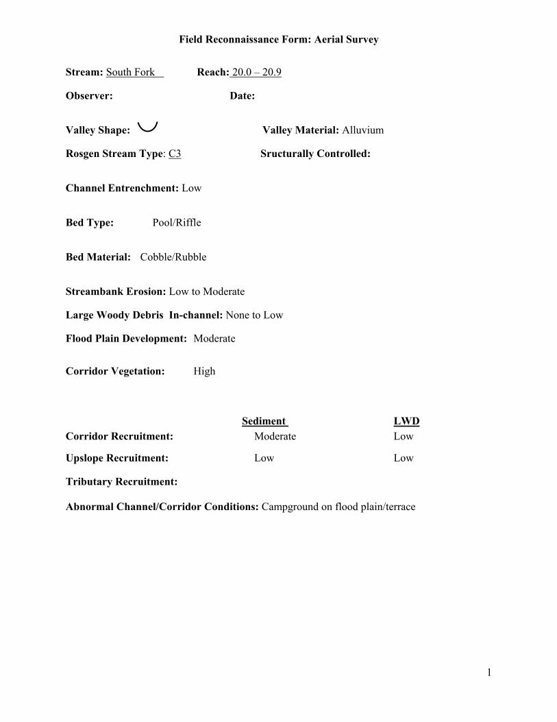
Field Reconnaissance Form: Aerial Survey
1
Stream: South Fork Reach: 20.0 – 20.9
Observer: Date:
Valley Shape: Valley Material: Alluvium
Rosgen Stream Type: C3 Sructurally Controlled:
Channel Entrenchment: Low
Bed Type: Pool/Riffle
Bed Material: Cobble/Rubble
Streambank Erosion: Low to Moderate
Large Woody Debris In-channel: None to Low
Flood Plain Development: Moderate
Corridor Vegetation: High
Sediment LWDCorridor Recruitment: Moderate Low
Upslope Recruitment: Low Low
Tributary Recruitment:
Abnormal Channel/Corridor Conditions: Campground on flood plain/terrace

Field Reconnaissance Form: Aerial Survey
2
Streambank Erosion
Bank Material: Alluvium
StreambankVegetation Cover: 0-25%
Bank Erosion: 5-20%
Lateral Migration: Probable
Describe indicators for lateral migration:
Upslope Sediment Recruitment
Upslope Material:
Upslope vegetation: Dense
Active Erosion: None
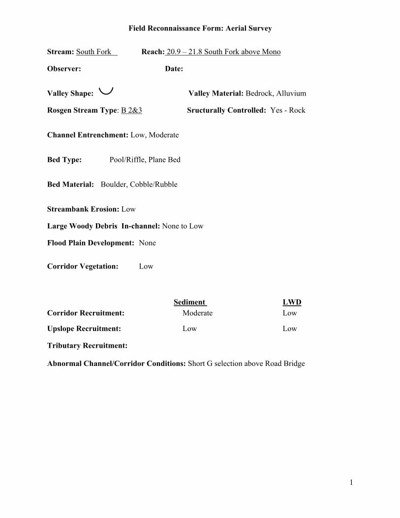
Field Reconnaissance Form: Aerial Survey
1
Stream: South Fork Reach: 20.9 – 21.8 South Fork above Mono
Observer: Date:
Valley Shape: Valley Material: Bedrock, Alluvium
Rosgen Stream Type: B 2&3 Sructurally Controlled: Yes - Rock
Channel Entrenchment: Low, Moderate
Bed Type: Pool/Riffle, Plane Bed
Bed Material: Boulder, Cobble/Rubble
Streambank Erosion: Low
Large Woody Debris In-channel: None to Low
Flood Plain Development: None
Corridor Vegetation: Low
Sediment LWDCorridor Recruitment: Moderate Low
Upslope Recruitment: Low Low
Tributary Recruitment:
Abnormal Channel/Corridor Conditions: Short G selection above Road Bridge
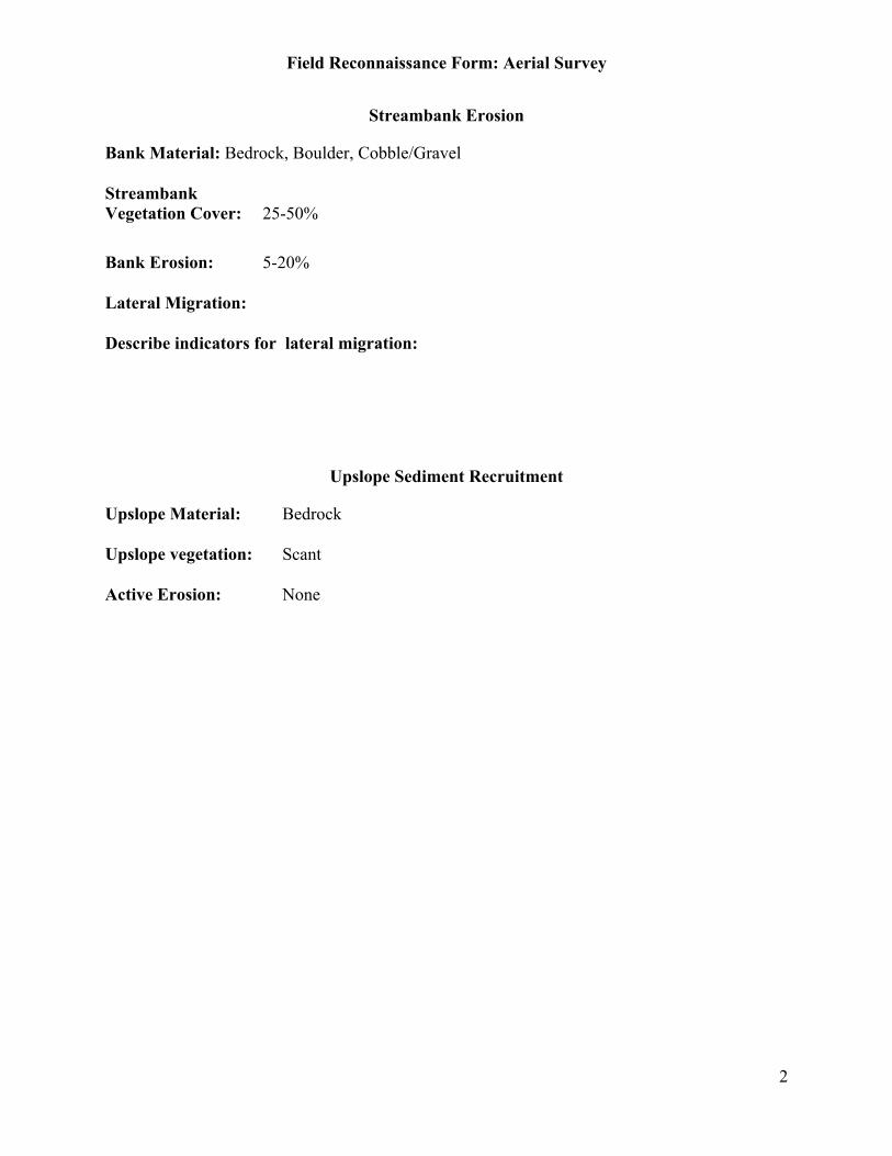
Field Reconnaissance Form: Aerial Survey
2
Streambank Erosion
Bank Material: Bedrock, Boulder, Cobble/Gravel
StreambankVegetation Cover: 25-50%
Bank Erosion: 5-20%
Lateral Migration:
Describe indicators for lateral migration:
Upslope Sediment Recruitment
Upslope Material: Bedrock
Upslope vegetation: Scant
Active Erosion: None
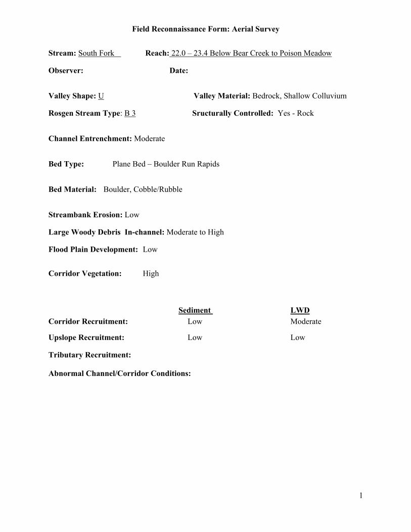
Field Reconnaissance Form: Aerial Survey
1
Stream: South Fork Reach: 22.0 – 23.4 Below Bear Creek to Poison Meadow
Observer: Date:
Valley Shape: U Valley Material: Bedrock, Shallow Colluvium
Rosgen Stream Type: B 3 Sructurally Controlled: Yes - Rock
Channel Entrenchment: Moderate
Bed Type: Plane Bed – Boulder Run Rapids
Bed Material: Boulder, Cobble/Rubble
Streambank Erosion: Low
Large Woody Debris In-channel: Moderate to High
Flood Plain Development: Low
Corridor Vegetation: High
Sediment LWDCorridor Recruitment: Low Moderate
Upslope Recruitment: Low Low
Tributary Recruitment:
Abnormal Channel/Corridor Conditions:
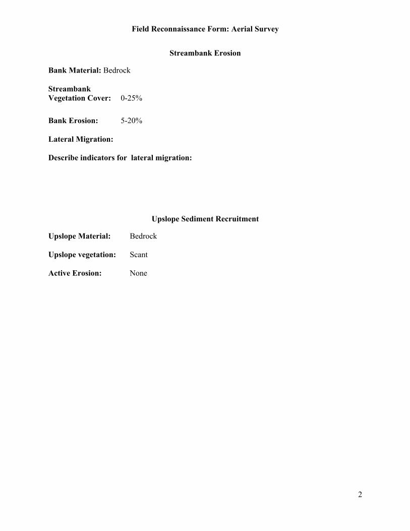
Field Reconnaissance Form: Aerial Survey
2
Streambank Erosion
Bank Material: Bedrock
StreambankVegetation Cover: 0-25%
Bank Erosion: 5-20%
Lateral Migration:
Describe indicators for lateral migration:
Upslope Sediment Recruitment
Upslope Material: Bedrock
Upslope vegetation: Scant
Active Erosion: None
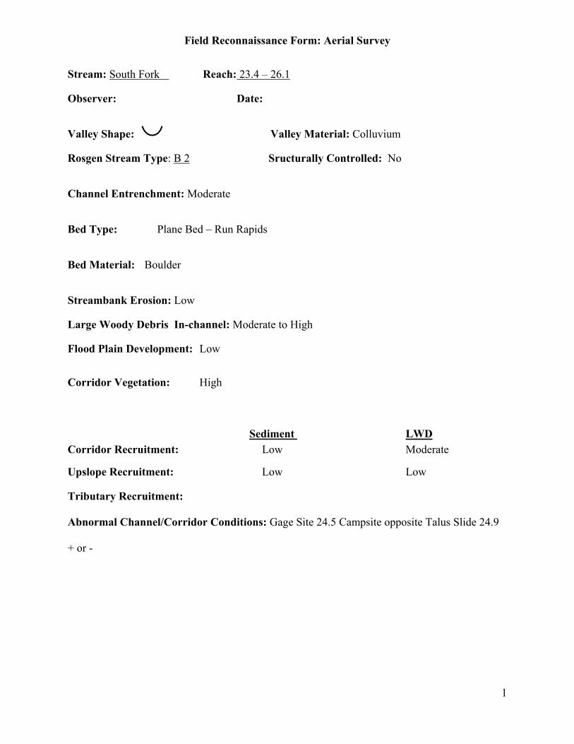
Field Reconnaissance Form: Aerial Survey
1
Stream: South Fork Reach: 23.4 – 26.1
Observer: Date:
Valley Shape: Valley Material: Colluvium
Rosgen Stream Type: B 2 Sructurally Controlled: No
Channel Entrenchment: Moderate
Bed Type: Plane Bed – Run Rapids
Bed Material: Boulder
Streambank Erosion: Low
Large Woody Debris In-channel: Moderate to High
Flood Plain Development: Low
Corridor Vegetation: High
Sediment LWDCorridor Recruitment: Low Moderate
Upslope Recruitment: Low Low
Tributary Recruitment:
Abnormal Channel/Corridor Conditions: Gage Site 24.5 Campsite opposite Talus Slide 24.9
+ or -
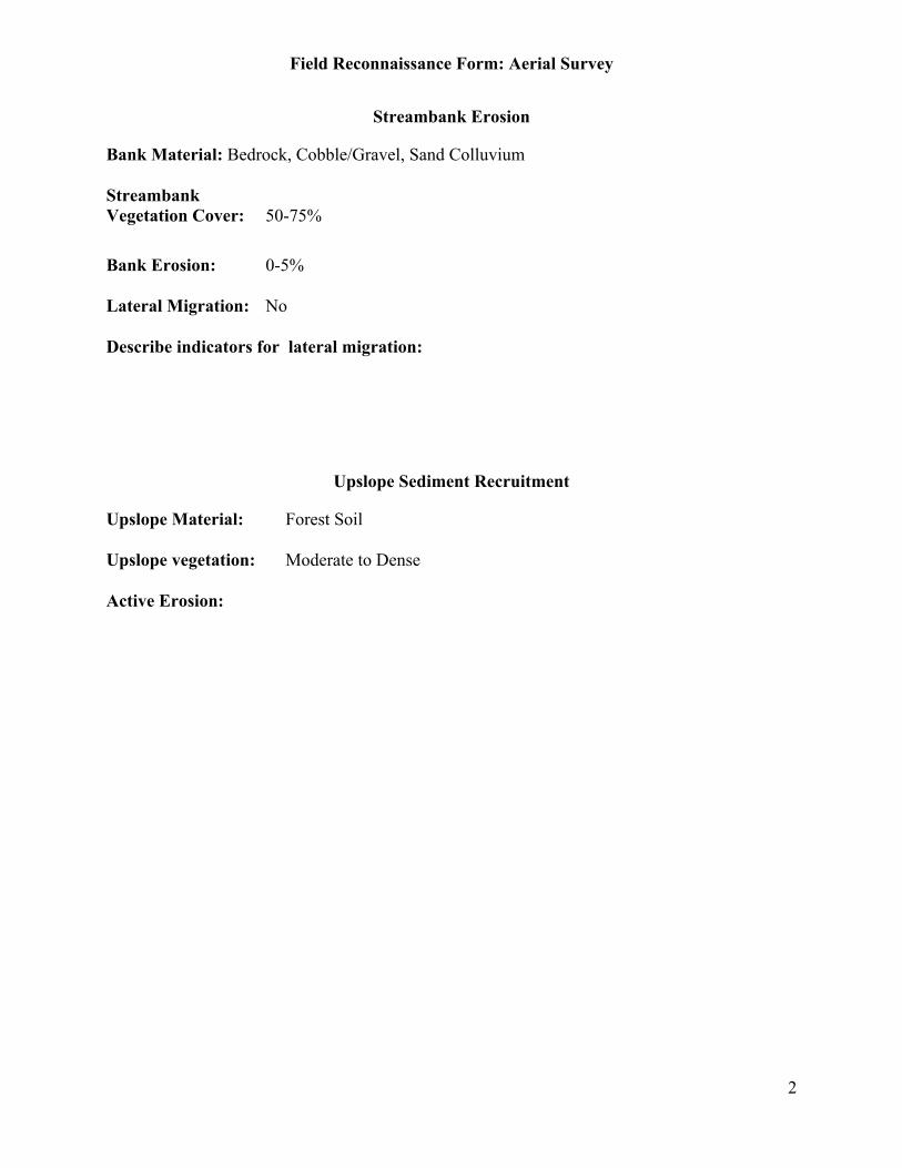
Field Reconnaissance Form: Aerial Survey
2
Streambank Erosion
Bank Material: Bedrock, Cobble/Gravel, Sand Colluvium
StreambankVegetation Cover: 50-75%
Bank Erosion: 0-5%
Lateral Migration: No
Describe indicators for lateral migration:
Upslope Sediment Recruitment
Upslope Material: Forest Soil
Upslope vegetation: Moderate to Dense
Active Erosion:
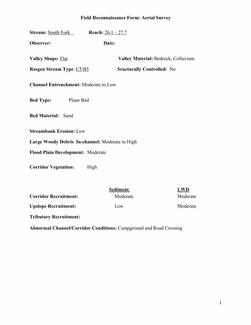
Field Reconnaissance Form: Aerial Survey
1
Stream: South Fork Reach: 26.1 – 27.7
Observer: Date:
Valley Shape: Flat Valley Material: Bedrock, Colluvium
Rosgen Stream Type: C5/B5 Sructurally Controlled: No
Channel Entrenchment: Moderate to Low
Bed Type: Plane Bed
Bed Material: Sand
Streambank Erosion: Low
Large Woody Debris In-channel: Moderate to High
Flood Plain Development: Moderate
Corridor Vegetation: High
Sediment LWDCorridor Recruitment: Moderate Moderate
Upslope Recruitment: Low Moderate
Tributary Recruitment:
Abnormal Channel/Corridor Conditions: Campground and Road Crossing
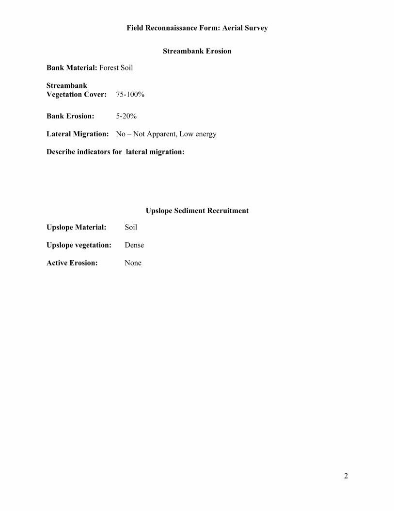
Field Reconnaissance Form: Aerial Survey
2
Streambank Erosion
Bank Material: Forest Soil
StreambankVegetation Cover: 75-100%
Bank Erosion: 5-20%
Lateral Migration: No – Not Apparent, Low energy
Describe indicators for lateral migration:
Upslope Sediment Recruitment
Upslope Material: Soil
Upslope vegetation: Dense
Active Erosion: None
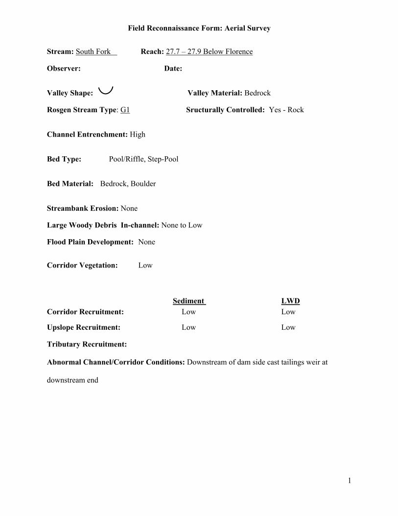
Field Reconnaissance Form: Aerial Survey
1
Stream: South Fork Reach: 27.7 – 27.9 Below Florence
Observer: Date:
Valley Shape: Valley Material: Bedrock
Rosgen Stream Type: G1 Sructurally Controlled: Yes - Rock
Channel Entrenchment: High
Bed Type: Pool/Riffle, Step-Pool
Bed Material: Bedrock, Boulder
Streambank Erosion: None
Large Woody Debris In-channel: None to Low
Flood Plain Development: None
Corridor Vegetation: Low
Sediment LWDCorridor Recruitment: Low Low
Upslope Recruitment: Low Low
Tributary Recruitment:
Abnormal Channel/Corridor Conditions: Downstream of dam side cast tailings weir at
downstream end

Field Reconnaissance Form: Aerial Survey
2
Streambank Erosion
Bank Material: Bedrock
StreambankVegetation Cover: 0-25%
Bank Erosion: 0-5%
Lateral Migration: No
Describe indicators for lateral migration:
Upslope Sediment Recruitment
Upslope Material: Bedrock
Upslope vegetation: None
Active Erosion: None
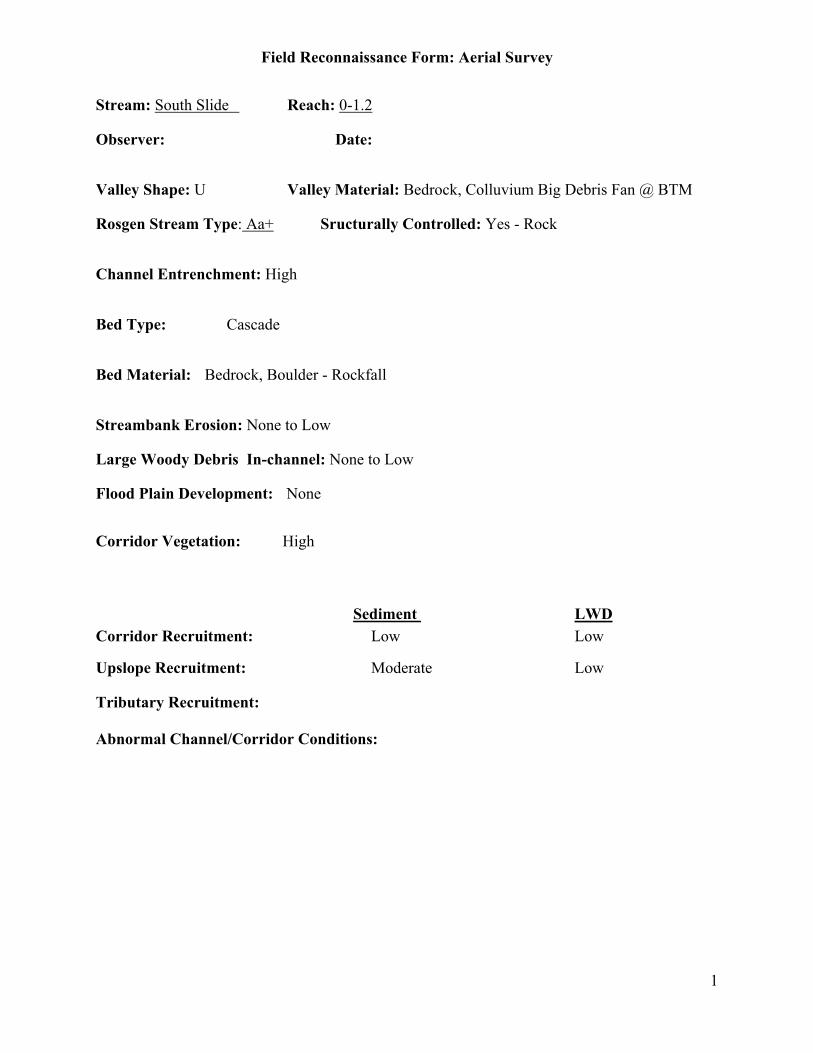
Field Reconnaissance Form: Aerial Survey
1
Stream: South Slide Reach: 0-1.2
Observer: Date:
Valley Shape: U Valley Material: Bedrock, Colluvium Big Debris Fan @ BTM
Rosgen Stream Type: Aa+ Sructurally Controlled: Yes - Rock
Channel Entrenchment: High
Bed Type: Cascade
Bed Material: Bedrock, Boulder - Rockfall
Streambank Erosion: None to Low
Large Woody Debris In-channel: None to Low
Flood Plain Development: None
Corridor Vegetation: High
Sediment LWDCorridor Recruitment: Low Low
Upslope Recruitment: Moderate Low
Tributary Recruitment:
Abnormal Channel/Corridor Conditions:

Field Reconnaissance Form: Aerial Survey
2
Streambank Erosion
Bank Material: Boulder
StreambankVegetation Cover: 75-100%
Bank Erosion: 0-5%
Lateral Migration: No
Describe indicators for lateral migration:
Upslope Sediment Recruitment
Upslope Material: Bedrock
Upslope vegetation: Scant
Active Erosion: Landslides – Debris Fan at bottom of slope, 0 – 0.2 or 0.3 mile
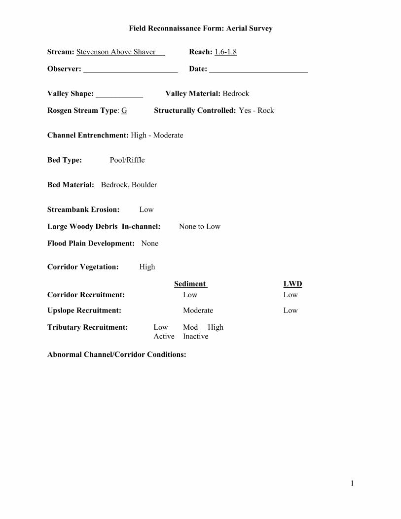
Field Reconnaissance Form: Aerial Survey
1
Stream: Stevenson Above Shaver Reach: 1.6-1.8
Observer: ________________________ Date: _________________________
Valley Shape: ____________ Valley Material: Bedrock
Rosgen Stream Type: G Structurally Controlled: Yes - Rock
Channel Entrenchment: High - Moderate
Bed Type: Pool/Riffle
Bed Material: Bedrock, Boulder
Streambank Erosion: Low
Large Woody Debris In-channel: None to Low
Flood Plain Development: None
Corridor Vegetation: High
Sediment LWDCorridor Recruitment: Low Low
Upslope Recruitment: Moderate Low
Tributary Recruitment: Low Mod HighActive Inactive
Abnormal Channel/Corridor Conditions:
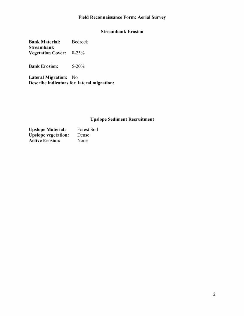
Field Reconnaissance Form: Aerial Survey
2
Streambank Erosion
Bank Material: BedrockStreambankVegetation Cover: 0-25%
Bank Erosion: 5-20%
Lateral Migration: NoDescribe indicators for lateral migration:
Upslope Sediment Recruitment
Upslope Material: Forest SoilUpslope vegetation: DenseActive Erosion: None

Field Reconnaissance Form: Aerial Survey
1
Stream: Stevenson Above Shaver Reach: 1.8 to 2.3
Observer: ________________________ Date: _________________________
Valley Shape: ____________ Valley Material: Alluvium
Rosgen Stream Type: B3 Structurally Controlled: No
Channel Entrenchment: Moderate
Bed Type: Pool/Riffle, Plane Beds (Runs)
Bed Material: Cobble/Rubble
Streambank Erosion: Low
Large Woody Debris In-channel: None to Low
Flood Plain Development: Moderate
Corridor Vegetation: High
Sediment LWDCorridor Recruitment: Moderate Moderate
Upslope Recruitment: Moderate Low-too far from Channel
Tributary Recruitment: Low Mod High
Active Inactive
Abnormal Channel/Corridor Conditions: Debris Flow deposition area, Good recoveryunderway

Field Reconnaissance Form: Aerial Survey
2
Streambank Erosion
Bank Material: Bedrock, Cobble/GravelStreambankVegetation Cover: 75-100%
Bank Erosion: 0-5%
Lateral Migration:
Describe indicators for lateral migration:
Upslope Sediment Recruitment
Upslope Material: Forest SoilUpslope vegetation: DenseActive Erosion: None
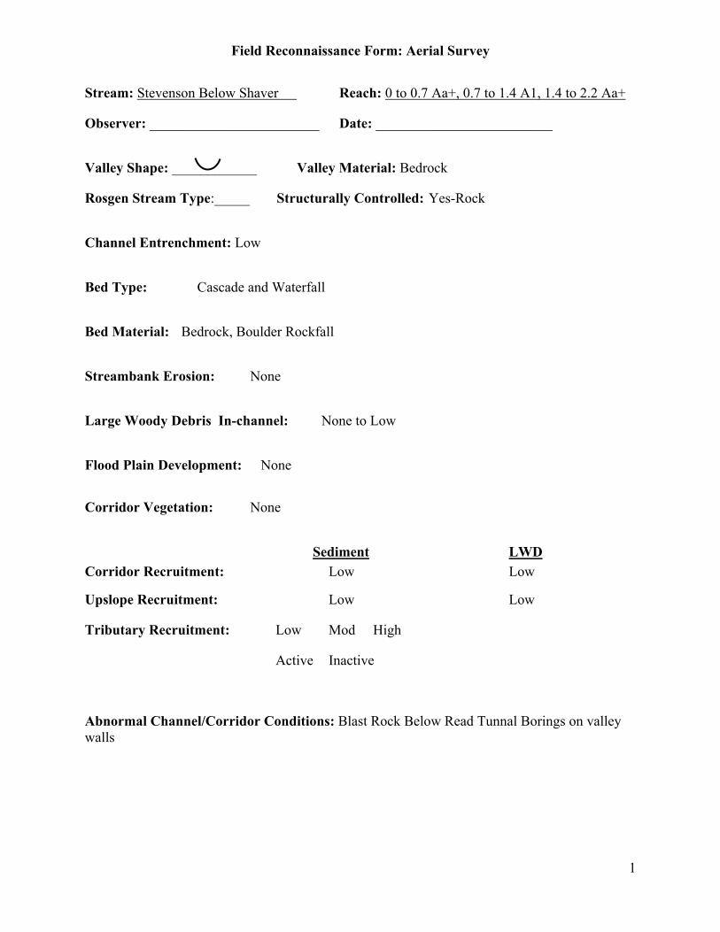
Field Reconnaissance Form: Aerial Survey
1
Stream: Stevenson Below Shaver Reach: 0 to 0.7 Aa+, 0.7 to 1.4 A1, 1.4 to 2.2 Aa+
Observer: ________________________ Date: _________________________
Valley Shape: ____________ Valley Material: Bedrock
Rosgen Stream Type:_____ Structurally Controlled: Yes-Rock
Channel Entrenchment: Low
Bed Type: Cascade and Waterfall
Bed Material: Bedrock, Boulder Rockfall
Streambank Erosion: None
Large Woody Debris In-channel: None to Low
Flood Plain Development: None
Corridor Vegetation: None
Sediment LWDCorridor Recruitment: Low Low
Upslope Recruitment: Low Low
Tributary Recruitment: Low Mod High
Active Inactive
Abnormal Channel/Corridor Conditions: Blast Rock Below Read Tunnal Borings on valleywalls
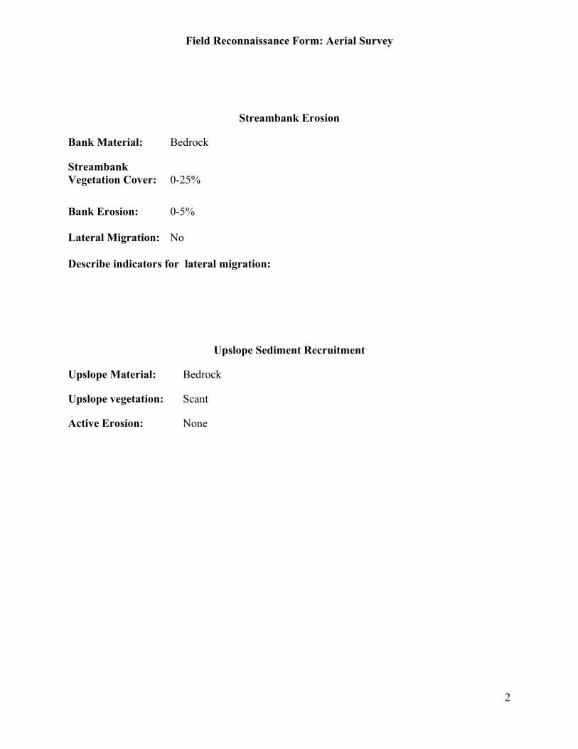
Field Reconnaissance Form: Aerial Survey
2
Streambank Erosion
Bank Material: Bedrock
StreambankVegetation Cover: 0-25%
Bank Erosion: 0-5%
Lateral Migration: No
Describe indicators for lateral migration:
Upslope Sediment Recruitment
Upslope Material: Bedrock
Upslope vegetation: Scant
Active Erosion: None
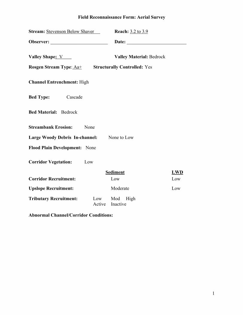
Field Reconnaissance Form: Aerial Survey
1
Stream: Stevenson Below Shaver Reach: 3.2 to 3.9
Observer: ________________________ Date: _________________________
Valley Shape: V Valley Material: Bedrock
Rosgen Stream Type: Aa+ Structurally Controlled: Yes
Channel Entrenchment: High
Bed Type: Cascade
Bed Material: Bedrock
Streambank Erosion: None
Large Woody Debris In-channel: None to Low
Flood Plain Development: None
Corridor Vegetation: Low
Sediment LWDCorridor Recruitment: Low Low
Upslope Recruitment: Moderate Low
Tributary Recruitment: Low Mod HighActive Inactive
Abnormal Channel/Corridor Conditions:
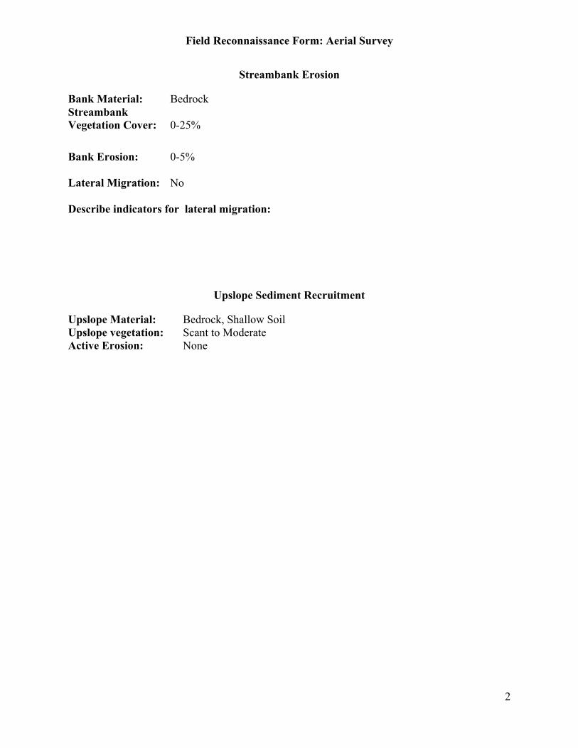
Field Reconnaissance Form: Aerial Survey
2
Streambank Erosion
Bank Material: BedrockStreambankVegetation Cover: 0-25%
Bank Erosion: 0-5%
Lateral Migration: No
Describe indicators for lateral migration:
Upslope Sediment Recruitment
Upslope Material: Bedrock, Shallow SoilUpslope vegetation: Scant to ModerateActive Erosion: None

Field Reconnaissance Form: Aerial Survey
1
Stream: Stevenson Below Shaver Reach: 2.7-3.2
Observer: ________________________ Date: _________________________
Valley Shape: ____________ Valley Material: Alluvium
Rosgen Stream Type: B3 Structurally Controlled: No
Channel Entrenchment: Moderate
Bed Type: Pool/Riffle, Plane Bed
Bed Material: Cobble/Rubble
Streambank Erosion: Low
Large Woody Debris In-channel: None to Low
Flood Plain Development: Low
Corridor Vegetation: High
Sediment LWDCorridor Recruitment: Moderate Low
Upslope Recruitment: Low Low-too flat
Tributary Recruitment: Low Mod HighActive Inactive
Abnormal Channel/Corridor Conditions:
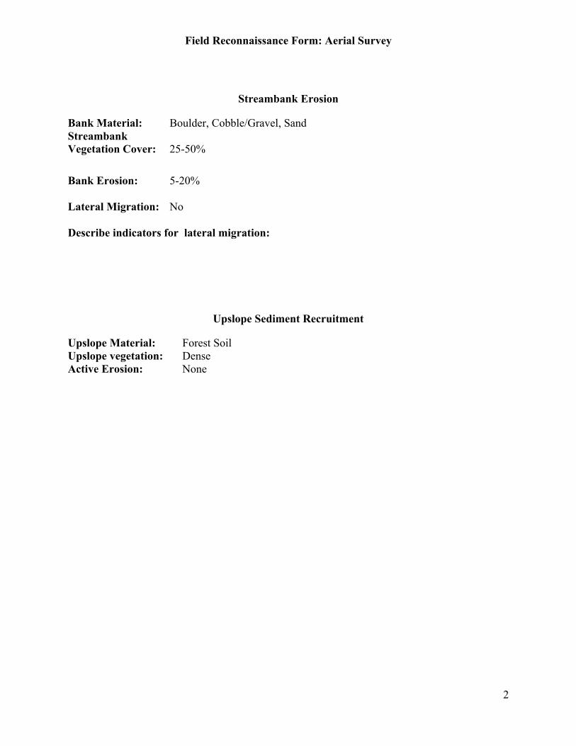
Field Reconnaissance Form: Aerial Survey
2
Streambank Erosion
Bank Material: Boulder, Cobble/Gravel, SandStreambankVegetation Cover: 25-50%
Bank Erosion: 5-20%
Lateral Migration: No
Describe indicators for lateral migration:
Upslope Sediment Recruitment
Upslope Material: Forest SoilUpslope vegetation: DenseActive Erosion: None

Field Reconnaissance Form: Aerial Survey
1
Stream: Stevenson Below Shaver Reach: 2.5 – 2.7
Observer: ________________________ Date: _________________________
Valley Shape: Valley Material: Bedrock
Rosgen Stream Type: Aa+ Structurally Controlled: Yes
Channel Entrenchment: High
Bed Type: Step-Pool, Cascade
Bed Material: Bedrock, Boulder
Streambank Erosion: None
Large Woody Debris In-channel: None
Flood Plain Development: None
Corridor Vegetation: Low
Sediment LWDCorridor Recruitment: Low Low
Upslope Recruitment: Low Low
Tributary Recruitment: Low Mod HighActive Inactive
Abnormal Channel/Corridor Conditions:
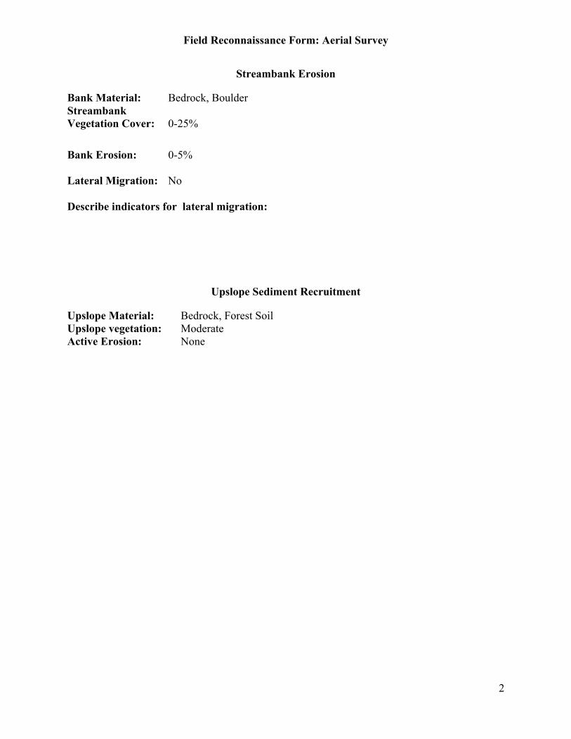
Field Reconnaissance Form: Aerial Survey
2
Streambank Erosion
Bank Material: Bedrock, BoulderStreambankVegetation Cover: 0-25%
Bank Erosion: 0-5%
Lateral Migration: No
Describe indicators for lateral migration:
Upslope Sediment Recruitment
Upslope Material: Bedrock, Forest SoilUpslope vegetation: ModerateActive Erosion: None

Field Reconnaissance Form: Aerial Survey
1
Stream: Stevenson Below Shaver Reach: 3.9-4.3
Observer: ________________________ Date: _________________________
Valley Shape: Valley Material: Alluvium
Rosgen Stream Type: G or B Structurally Controlled: No
Channel Entrenchment: High
Bed Type: Pool/Riffle
Bed Material: Boulder, Sand
Streambank Erosion: Moderate
Large Woody Debris In-channel: Low
Flood Plain Development: Low
Corridor Vegetation: High
Sediment LWDCorridor Recruitment: Moderate Low
Upslope Recruitment: Low Moderate
Tributary Recruitment: Low Mod HighActive Inactive
Abnormal Channel/Corridor Conditions: Immediately Below Dam, No Spillway

Field Reconnaissance Form: Aerial Survey
2
Streambank Erosion
Bank Material: Bedrock, Sand
StreambankVegetation Cover: 75-100%
Bank Erosion: 5-20%
Lateral Migration: No
Describe indicators for lateral migration:
Upslope Sediment Recruitment
Upslope Material: Forest SoilUpslope vegetation: DenseActive Erosion: None
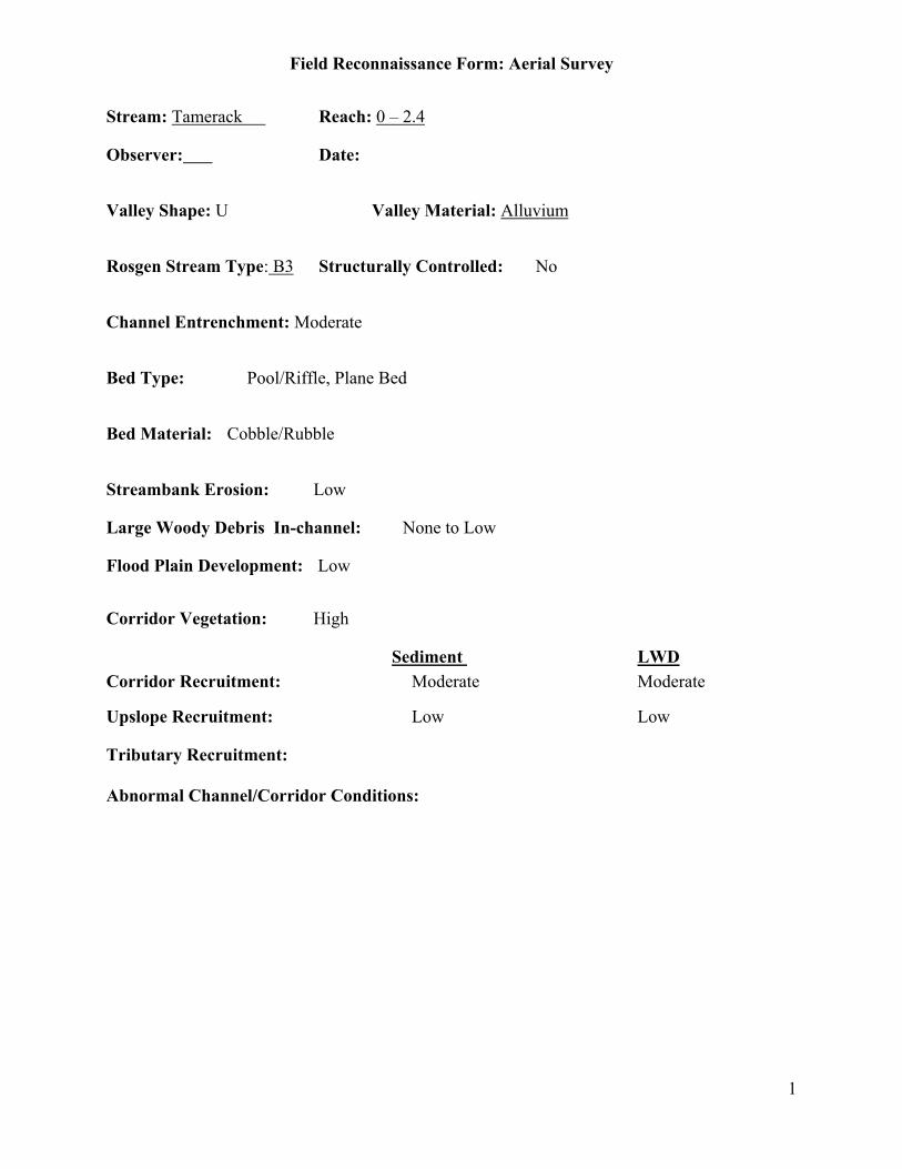
Field Reconnaissance Form: Aerial Survey
1
Stream: Tamerack Reach: 0 – 2.4
Observer: Date:
Valley Shape: U Valley Material: Alluvium
Rosgen Stream Type: B3 Structurally Controlled: No
Channel Entrenchment: Moderate
Bed Type: Pool/Riffle, Plane Bed
Bed Material: Cobble/Rubble
Streambank Erosion: Low
Large Woody Debris In-channel: None to Low
Flood Plain Development: Low
Corridor Vegetation: High
Sediment LWDCorridor Recruitment: Moderate Moderate
Upslope Recruitment: Low Low
Tributary Recruitment:
Abnormal Channel/Corridor Conditions:
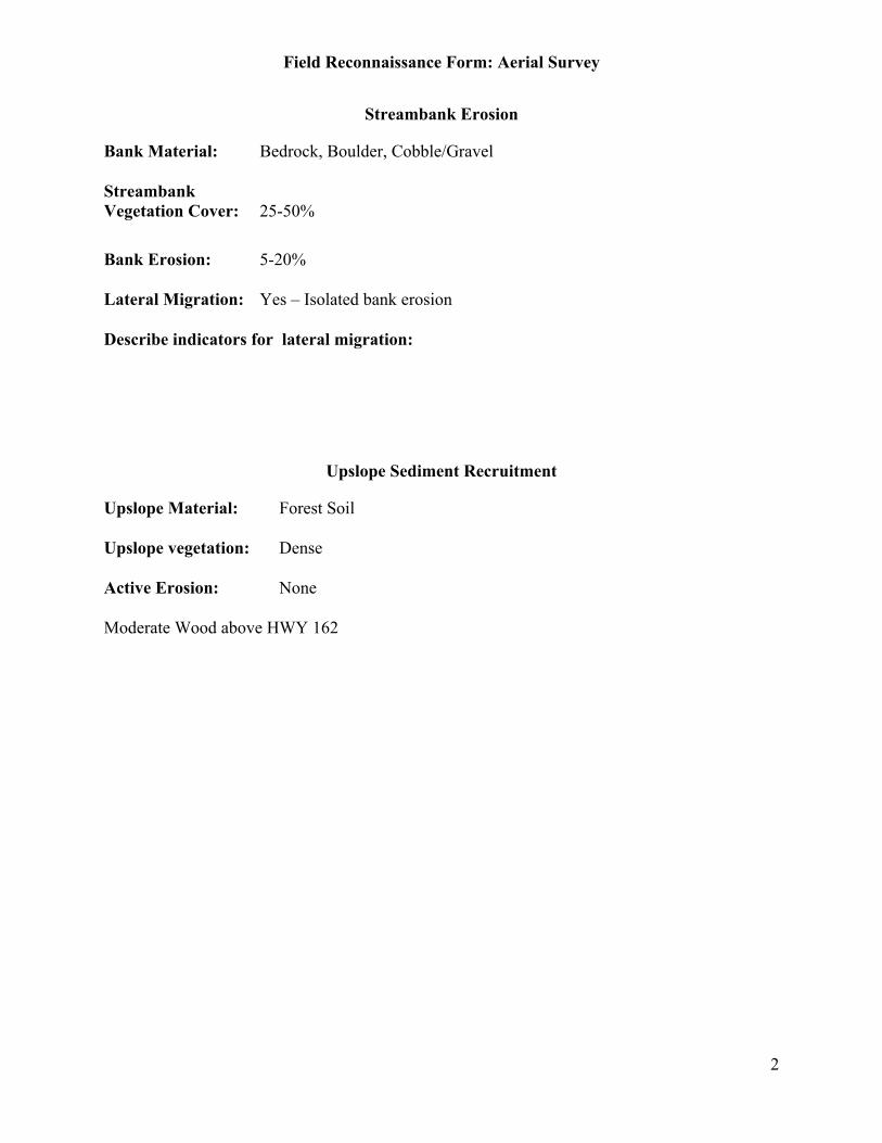
Field Reconnaissance Form: Aerial Survey
2
Streambank Erosion
Bank Material: Bedrock, Boulder, Cobble/Gravel
StreambankVegetation Cover: 25-50%
Bank Erosion: 5-20%
Lateral Migration: Yes – Isolated bank erosion
Describe indicators for lateral migration:
Upslope Sediment Recruitment
Upslope Material: Forest Soil
Upslope vegetation: Dense
Active Erosion: None
Moderate Wood above HWY 162
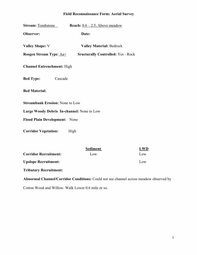
Field Reconnaissance Form: Aerial Survey
1
Stream: Tombstone Reach: 0.6 – 2.5, Above meadow
Observer: Date:
Valley Shape: V Valley Material: Bedrock
Rosgen Stream Type: Aa+ Sructurally Controlled: Yes - Rock
Channel Entrenchment: High
Bed Type: Cascade
Bed Material:
Streambank Erosion: None to Low
Large Woody Debris In-channel: None to Low
Flood Plain Development: None
Corridor Vegetation: High
Sediment LWDCorridor Recruitment: Low Low
Upslope Recruitment: Low
Tributary Recruitment:
Abnormal Channel/Corridor Conditions: Could not see channel across meadow observed by
Cotton Wood and Willow. Walk Lower 0.6 mile or so.

Field Reconnaissance Form: Aerial Survey
2
Streambank Erosion
Bank Material: Boulder
StreambankVegetation Cover: 50-75%
Bank Erosion: 0-5%
Lateral Migration: No
Describe indicators for lateral migration:
Upslope Sediment Recruitment
Upslope Material: Bedrock
Upslope vegetation: Scant
Active Erosion: None

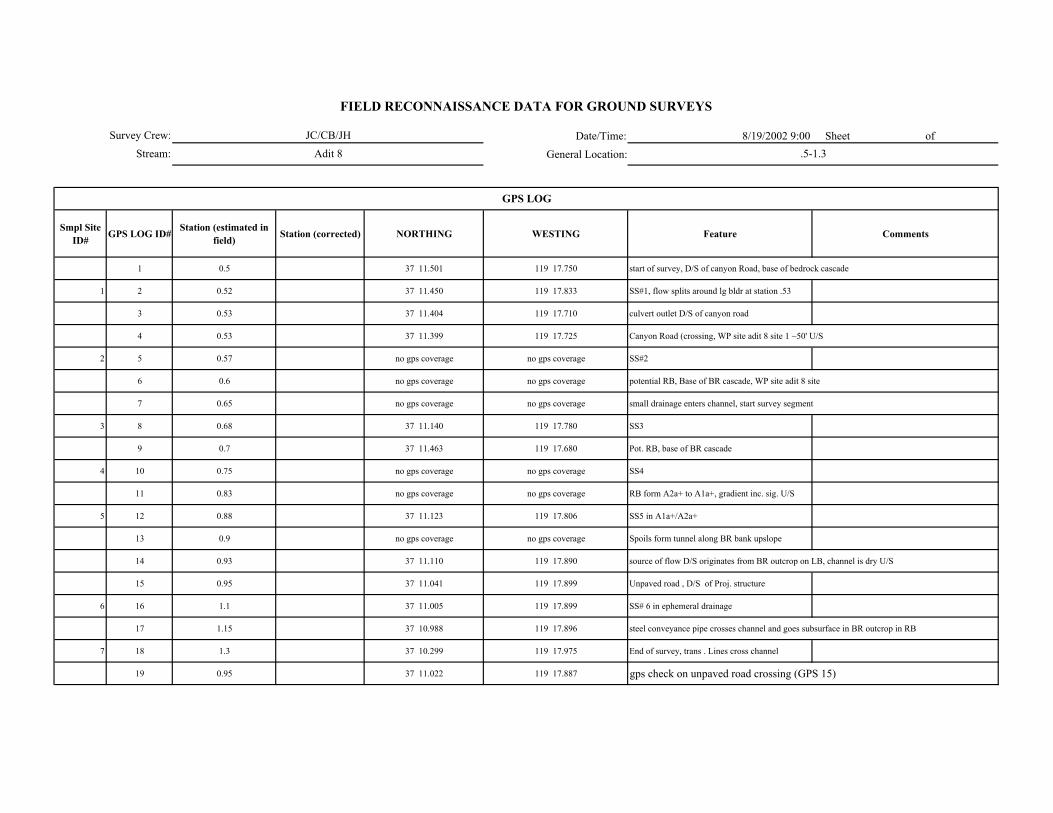
Date/Time: 8/19/2002 9:00 Sheet of
General Location:
Smpl Site ID# GPS LOG ID# Station (estimated in
field) Station (corrected) NORTHING WESTING Feature Comments
1 0.5 37 11.501 119 17.750 start of survey, D/S of canyon Road, base of bedrock cascade
1 2 0.52 37 11.450 119 17.833 SS#1, flow splits around lg bldr at station .53
3 0.53 37 11.404 119 17.710 culvert outlet D/S of canyon road
4 0.53 37 11.399 119 17.725 Canyon Road (crossing, WP site adit 8 site 1 ~50' U/S
2 5 0.57 no gps coverage no gps coverage SS#2
6 0.6 no gps coverage no gps coverage potential RB, Base of BR cascade, WP site adit 8 site
7 0.65 no gps coverage no gps coverage small drainage enters channel, start survey segment
3 8 0.68 37 11.140 119 17.780 SS3
9 0.7 37 11.463 119 17.680 Pot. RB, base of BR cascade
4 10 0.75 no gps coverage no gps coverage SS4
11 0.83 no gps coverage no gps coverage RB form A2a+ to A1a+, gradient inc. sig. U/S
5 12 0.88 37 11.123 119 17.806 SS5 in A1a+/A2a+
13 0.9 no gps coverage no gps coverage Spoils form tunnel along BR bank upslope
14 0.93 37 11.110 119 17.890 source of flow D/S originates from BR outcrop on LB, channel is dry U/S
15 0.95 37 11.041 119 17.899 Unpaved road , D/S of Proj. structure
6 16 1.1 37 11.005 119 17.899 SS# 6 in ephemeral drainage
17 1.15 37 10.988 119 17.896 steel conveyance pipe crosses channel and goes subsurface in BR outcrop in RB
7 18 1.3 37 10.299 119 17.975 End of survey, trans . Lines cross channel
19 0.95 37 11.022 119 17.887 gps check on unpaved road crossing (GPS 15)
GPS LOG
Survey Crew:
Stream:
FIELD RECONNAISSANCE DATA FOR GROUND SURVEYS
JC/CB/JH
Adit 8 .5-1.3
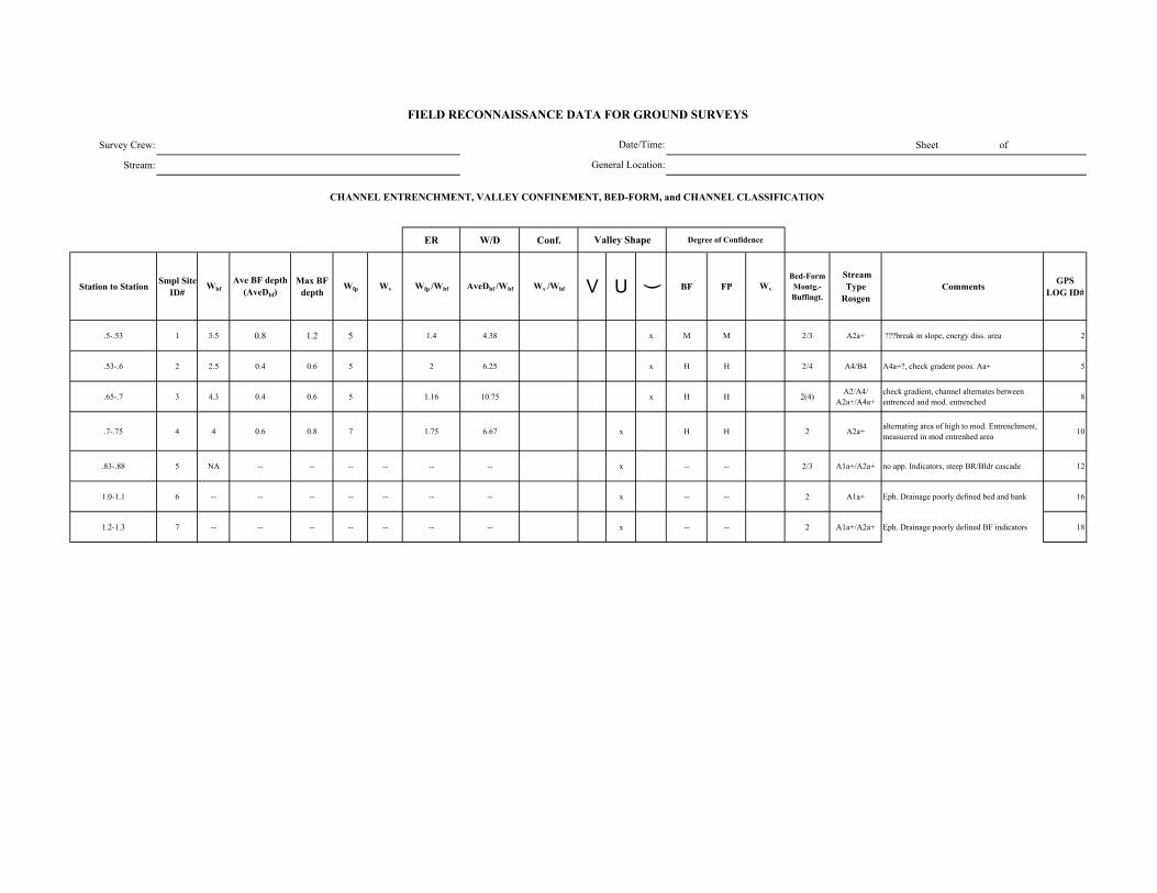
Survey Crew: Sheet of
Stream:
ER W/D Conf.
Station to Station Smpl Site ID#
WbfAve BF depth
(AveDbf)Max BF
depthWfp Wv Wfp /Wbf AveDbf /Wbf Wv /Wbf V U ( BF FP Wv
Bed-Form Montg.-Buffingt.
Stream Type
RosgenComments GPS
LOG ID#
.5-.53 1 3.5 0.8 1.2 5 1.4 4.38 x M M 2/3 A2a+ ???break in slope, energy diss. area 2
.53-.6 2 2.5 0.4 0.6 5 2 6.25 x H H 2/4 A4/B4 A4a+?, check gradent poos. Aa+ 5
.65-.7 3 4.3 0.4 0.6 5 1.16 10.75 x H H 2(4) A2/A4/ A2a+/A4a+
check gradient, channel alternates between entrenced and mod. entrenched 8
.7-.75 4 4 0.6 0.8 7 1.75 6.67 x H H 2 A2a+ alternating area of high to mod. Entrenchment, measuered in mod entrenhed area 10
.83-.88 5 NA -- -- -- -- -- -- x -- -- 2/3 A1a+/A2a+ no app. Indicators, steep BR/Bldr cascade 12
1.0-1.1 6 -- -- -- -- -- -- -- x -- -- 2 A1a+ Eph. Drainage poorly defined bed and bank 16
1.2-1.3 7 -- -- -- -- -- -- -- x -- -- 2 A1a+/A2a+ Eph. Drainage poorly defined BF indicators 18
FIELD RECONNAISSANCE DATA FOR GROUND SURVEYS
Degree of Confidence
CHANNEL ENTRENCHMENT, VALLEY CONFINEMENT, BED-FORM, and CHANNEL CLASSIFICATION
Valley Shape
Date/Time:
General Location:

Survey Crew: Date/Time:
Stream: General Location:
Smpl Site ID# Smpl Site ID# Bedrock Lg. Boulder (512-4096 mm)
Sm. Boulder (256-512 mm)
Cobble (64-256 mm)
Gravel (2-64 mm)
Sand/ Fines (<2mm)
1 5 60 20 10 3 2
2 -- 10 10 70 10
3 -- -- 40 10 40 10
4 5 30 30 20 10 5
5 40 40 10 2 4 4
6 70 20 -- -- -- 10
7 50 15 15 -- -- 20
FIELD RECONNAISSANCE DATA FOR GROUND SURVEYS
DOMINANT STREAMBED PARTICLE SIZE
Sheet of
Comments
Org. mtl on bed
Org. mtl on bed
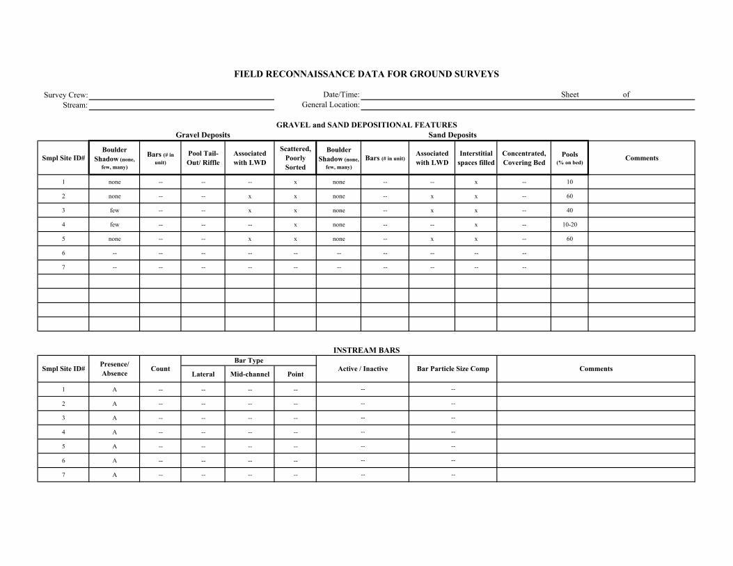
Survey Crew:Stream:
Smpl Site ID# Boulder
Shadow (none, few, many)
Bars (# in unit)
Pool Tail-Out/ Riffle
Associated with LWD
Scattered, Poorly Sorted
Boulder Shadow (none,
few, many)Bars (# in unit)
Associated with LWD
Interstitial spaces filled
Concentrated, Covering Bed
Pools (% on bed)
Comments
1 none -- -- -- x none -- -- x -- 10
2 none -- -- x x none -- x x -- 60
3 few -- -- x x none -- x x -- 40
4 few -- -- -- x none -- -- x -- 10-20
5 none -- -- x x none -- x x -- 60
6 -- -- -- -- -- -- -- -- -- --
7 -- -- -- -- -- -- -- -- -- --
Lateral Mid-channel Point
1 A -- -- -- --
2 A -- -- -- --
3 A -- -- -- --
4 A -- -- -- --
5 A -- -- -- --
6 A -- -- -- --
7 A -- -- -- --
Comments
Sand Deposits
INSTREAM BARS
Presence/ Absence Count Active / Inactive Bar Particle Size Comp
Bar Type
FIELD RECONNAISSANCE DATA FOR GROUND SURVEYS
Date/Time:General Location:
Sheet of
GRAVEL and SAND DEPOSITIONAL FEATURESGravel Deposits
Smpl Site ID#
--
--
--
--
--
--
--
--
--
--
--
--
--
--
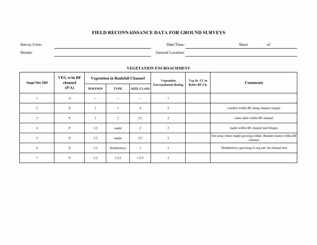
Survey Crew: Date/Time: Sheet of
Stream: General Location:
Vegetation in Bankfull Channel
POSTION TYPE SIZE CLASS
1 A -- -- -- 1
2 P 1 1 4 2
3 P 1 2 2/3 2
4 P 1/2 maple 2 2
5 P 1/2 maple 2/3 2
6 P 1/2 thimbleberry 1 3
7 P 1/2 1/2/5 1/2/3 3
Thimbleberry growning in org mtl. On channel bed
conifers within BF along channel margin
some alder within BF channel
maple within BF channel and Margin
few areas where maple growing within Boulder matrix within BF channel
Comments
VEGETATION ENCROACHMENT
FIELD RECONNAISSANCE DATA FOR GROUND SURVEYS
Smpl Site ID# VEG w/in BF
channel (P/A)
Vegetation Encroachment Rating
Veg Sz. Cl. in Relict BF Ch.

Survey Crew: Date/Time: Sheet of
Stream: General Location:
Smpl Site ID# Erodibility (yes /no)
Bank Composition Instability Feature Causative Erosion Process SCI Stability Rating Comments
1 N 1 0 0 STABLE few intermittent areas where sand present and scour is evident
2 Y 3/4 3 2 VULNERABLE veg provides stability
3 Y 2/3 3 2 VULNERABLE course mtl and veg provide stability
4 N 1/2 3 2 STABLE few intermitent areas where sand present and scour is evident
5 N 1 0 0 STABLE
6 N 21 0 0 STABLE poorly defined bed/bank -eph dom., coarse matl/BR provides stab.
7 N 1/2 0 0 STABLE coarse matl. Provides stability
FIELD RECONNAISSANCE DATA FOR GROUND SURVEYS
BANK STABILITY

Survey Crew: Date/Time:
Stream: General Location:
Smpl Site ID# Upslope Streambank Size of Erosion / Deposition Feature
Dominant Particle Size
1 4 -- unit 6
2 4 1/2 unit 6
3 4 1/2 unit 6
4 4 1/2 50% unit 6
5 4 -- unit 6
6 4 -- unit 6
7 4 -- unit 6
Smpl Site ID# Deposition / No Deposition Active/ Inactive Size of Deposition Dominant Particle
Size
Sheet of
FIELD RECONNAISSANCE DATA FOR GROUND SURVEYS
Comments
Tributary Deposition
STREAM-SIDE SEDIMENT SOURCES
Comments
sand/OM from upslope
sand/OM from upslope
sand/OM from upslope
scoured/undercut banks where sand present ~50%
sand/OM from upslope esp. in vicinty of area along RB
sand/OM from upslope
sand/OM from upslope
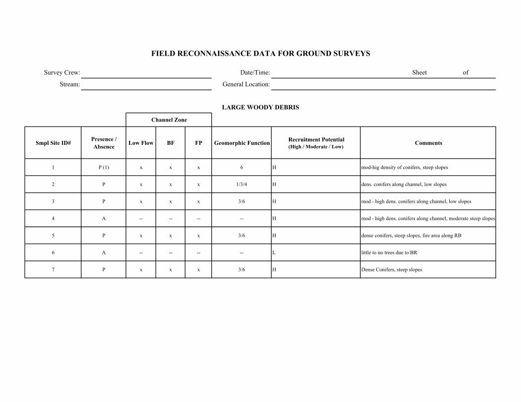
Survey Crew: Date/Time: Sheet of
Stream: General Location:
Smpl Site ID# Presence / Absence Low Flow BF FP Geomorphic Function Recruitment Potential
(High / Moderate / Low)Comments
1 P (1) x x x 6 H mod-hig density of conifers, steep slopes
2 P x x x 1/3/4 H dens. conifers along channel, low slopes
3 P x x x 3/6 H mod - high dens. conifers along channel, low slopes
4 A -- -- -- -- H mod - high dens. conifers along channel, moderate steep slopes
5 P x x x 3/6 H dense conifers, steep slopes, fire area along RB
6 A -- -- -- -- L little to no trees due to BR
7 P x x x 3/6 H Dense Conifers, steep slopes
FIELD RECONNAISSANCE DATA FOR GROUND SURVEYS
LARGE WOODY DEBRIS
Channel Zone

Date/Time: 8/9/2002 Sheet of General Location:
Smpl Site ID# GPS LOG ID# Station (estimated in
field) Photos NORTHING WESTING Feature Comments
1 0 45-46 37 11.775 119 15.670 Big Ck conf bar, lg mid channel bar D/S of mouth Aa+
1 2 0.03 37 11.758 119 15.671 site 1 150' U/S in A2a+ (lower grad portion)
2 3 0.1 37 11.695 119 15.690 site 2 570' in A1a+ (BR sheet and trench)
4 0.13 37 11.669 119 15.702 break (sm) to B? ~690' low grad
3 5 0.15 37 11.647 119 15.695 site 3 ~810' in lwr gradient before huge Aa+ Falls
6 0.17 47 no gps no gps Break to Aa+ 100' U/S of site 3
7 0.29 37 11.537 119 15.697 top of falls and above gravel pipe @ 1550, sm B secion 100' length
8 0.37 37 11.480 119 15.646 1990' camp sierra rd culvert (Aa+ U/S and D/S) BR control, some bldr
9 0.44 48-2320' 37 11.486 119 15.642 top of falls / base of sm camp sierra swimming hole - concete w/ weir
4 10 0.5 49 37 11.409 119 15.590 site 4 A 2670 U/S ~200' U/S of swimming hole/ Under transmissions lines
11 0.53 no gps no gps 2782 Aa+ (A1a+) ~50 U/S of trans. Lines w/in B?
12 0.54 no gps no gps sm trib @ 2842 (A2a+ w/ much sand)
13 0.59 no gps no gps 3125 break B to A1a+ - 100' bldr deposit and base of falls U/S powerlines / D/S of BC Rd
14 0.64 37 11.278 119 15.562 Big Cr Road Bridge
maybe flatter B above fall U/S of Rd
GPS LOG
Survey Crew:Stream:
FIELD RECONNAISSANCE DATA FOR GROUND SURVEYS
MC/RFBalsam Big Creek conf - RM 0.6
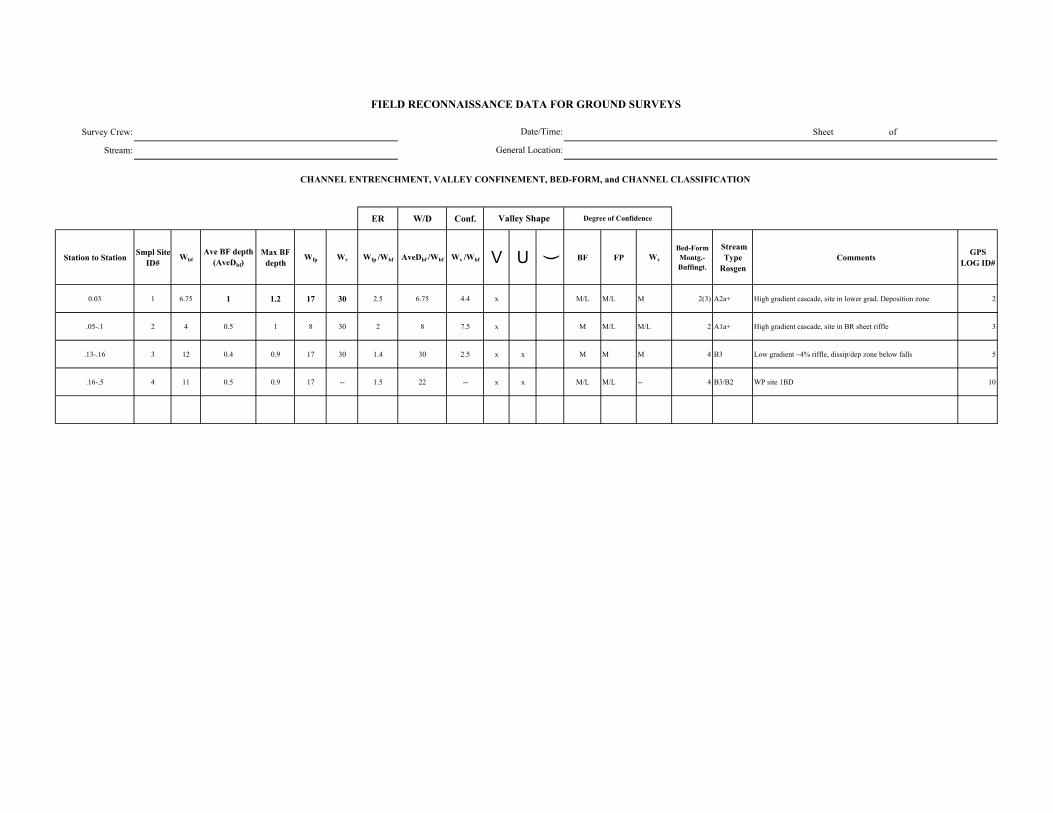
Survey Crew: Sheet of
Stream:
ER W/D Conf.
Station to Station Smpl Site ID#
WbfAve BF depth
(AveDbf)Max BF
depthWfp Wv Wfp /Wbf AveDbf /Wbf Wv /Wbf V U ( BF FP Wv
Bed-Form Montg.-Buffingt.
Stream Type
RosgenComments GPS
LOG ID#
0.03 1 6.75 1 1.2 17 30 2.5 6.75 4.4 x M/L M/L M 2(3) A2a+ High gradient cascade, site in lower grad. Deposition zone 2
.05-.1 2 4 0.5 1 8 30 2 8 7.5 x M M/L M/L 2 A1a+ High gradient cascade, site in BR sheet riffle 3
.13-.16 3 12 0.4 0.9 17 30 1.4 30 2.5 x x M M M 4 B3 Low gradient ~4% riffle, dissip/dep zone below falls 5
.16-.5 4 11 0.5 0.9 17 -- 1.5 22 -- x x M/L M/L -- 4 B3/B2 WP site 1BD 10
FIELD RECONNAISSANCE DATA FOR GROUND SURVEYS
Degree of Confidence
CHANNEL ENTRENCHMENT, VALLEY CONFINEMENT, BED-FORM, and CHANNEL CLASSIFICATION
Valley Shape
Date/Time:
General Location:
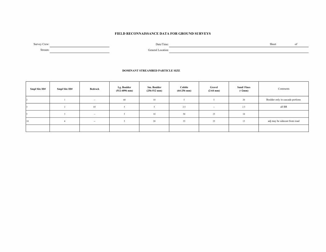
Date/Time:
General Location:
DOMINANT STREAMBED PARTICLE SIZE
Smpl Site ID# Smpl Site ID# Bedrock Lg. Boulder (512-4096 mm)
Sm. Boulder (256-512 mm)
Cobble (64-256 mm)
Gravel (2-64 mm)
Sand/ Fines (<2mm)
2 1 -- 60 10 5 5 20
3 2 85 5 5 2.5 -- 2.5
5 3 -- 5 10 50 25 10
10 4 -- 5 20 35 25 15
FIELD RECONNAISSANCE DATA FOR GROUND SURVEYS
Sheet of
Comments
Boulder only in cascade portions
all BR
adj may be sidecast from road
Survey Crew:
Stream:
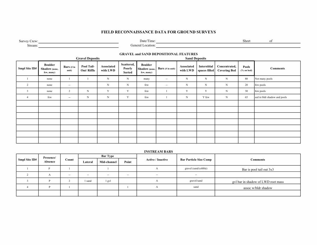
Survey Crew:Stream:
Smpl Site ID# Boulder
Shadow (none, few, many)
Bars (# in unit)
Pool Tail-Out/ Riffle
Associated with LWD
Scattered, Poorly Sorted
Boulder Shadow (none,
few, many)Bars (# in unit)
Associated with LWD
Interstitial spaces filled
Concentrated, Covering Bed
Pools (% on bed)
Comments
1 none 1 1 N N many -- N N N 80 Not many pools
2 none -- N N few -- N N N 20 few pools
3 none 2 N Y Y few 1 Y Y N 30 few pools
4 few -- N N Y few 1 N Y few N 65 sed in bldr shadow and pools
Lateral Mid-channel Point
1 P 1 1
2 A -- -- -- --
3 P 2 1 sand 1 gvl
4 P 1 1
Comments
Sand Deposits
INSTREAM BARS
Presence/ Absence Count Active / Inactive Bar Particle Size Comp
Bar Type
FIELD RECONNAISSANCE DATA FOR GROUND SURVEYS
Date/Time:General Location:
Sheet of
GRAVEL and SAND DEPOSITIONAL FEATURESGravel Deposits
Smpl Site ID#
Bar is pool tail out 3x3
gvl bar in shadow of LWD root mass
assoc w/bldr shadow
gravel (sand/cobble)
--
gravel/sand
sand
A
--
A
A
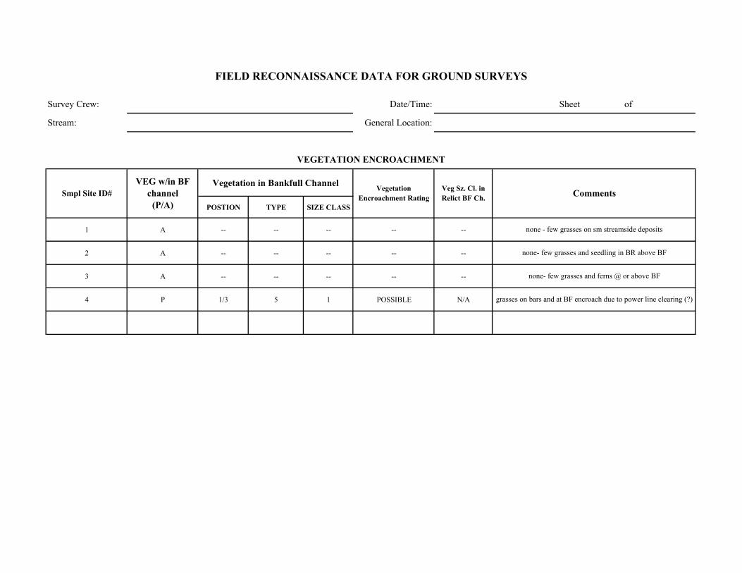
Survey Crew: Date/Time: Sheet of
Stream: General Location:
Vegetation in Bankfull Channel
POSTION TYPE SIZE CLASS
1 A -- -- -- -- --
2 A -- -- -- -- --
3 A -- -- -- -- --
4 P 1/3 5 1 POSSIBLE N/A
none - few grasses on sm streamside deposits
none- few grasses and seedling in BR above BF
none- few grasses and ferns @ or above BF
grasses on bars and at BF encroach due to power line clearing (?)
Comments
VEGETATION ENCROACHMENT
FIELD RECONNAISSANCE DATA FOR GROUND SURVEYS
Smpl Site ID# VEG w/in BF
channel (P/A)
Vegetation Encroachment Rating
Veg Sz. Cl. in Relict BF Ch.
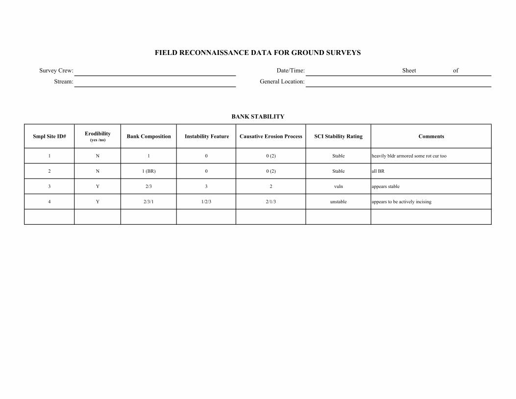
Survey Crew: Date/Time: Sheet of
Stream: General Location:
Smpl Site ID# Erodibility (yes /no)
Bank Composition Instability Feature Causative Erosion Process SCI Stability Rating Comments
1 N 1 0 0 (2) Stable heavily bldr armored some rot cur too
2 N 1 (BR) 0 0 (2) Stable all BR
3 Y 2/3 3 2 vuln appears stable
4 Y 2/3/1 1/2/3 2/1/3 unstable appears to be actively incising
FIELD RECONNAISSANCE DATA FOR GROUND SURVEYS
BANK STABILITY

Survey Crew: Date/Time:
Stream: General Location:
Smpl Site ID# Upslope Streambank Size of Erosion / Deposition Feature
Dominant Particle Size
1 4 1 unit 6
2 4 minor n/a unit 6
3 4 1 unit 6
4 1/4 1/2/3 75% unit 6
Smpl Site ID# Deposition / No Deposition Active/ Inactive Size of Deposition Dominant Particle
Size
Sheet of
FIELD RECONNAISSANCE DATA FOR GROUND SURVEYS
Comments
Tributary Deposition
STREAM-SIDE SEDIMENT SOURCES
Comments
steep upslope w/ some loose soil covered w/ duff
non-erodible -some upslope or upstream sand
sediment from upstream transport and upslope
inscision causing loose unprotected banks to slump and slide
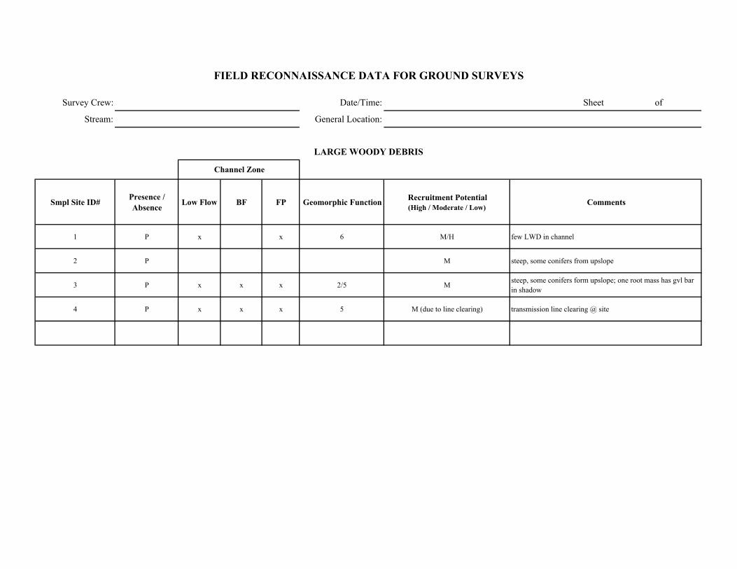
Survey Crew: Date/Time: Sheet of
Stream: General Location:
Smpl Site ID# Presence / Absence Low Flow BF FP Geomorphic Function Recruitment Potential
(High / Moderate / Low)Comments
1 P x x 6 M/H few LWD in channel
2 P M steep, some conifers from upslope
3 P x x x 2/5 M steep, some conifers form upslope; one root mass has gvl bar in shadow
4 P x x x 5 M (due to line clearing) transmission line clearing @ site
FIELD RECONNAISSANCE DATA FOR GROUND SURVEYS
LARGE WOODY DEBRIS
Channel Zone
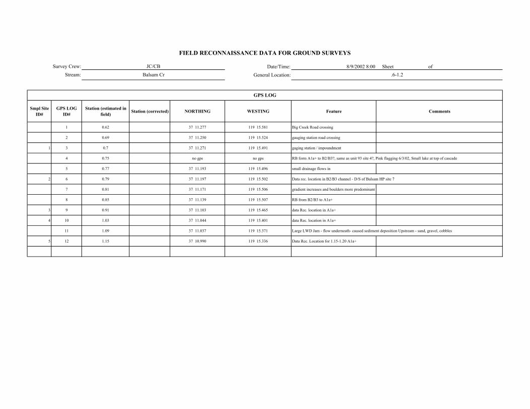
Date/Time: 8/9/2002 8:00 Sheet of General Location:
Smpl Site ID#
GPS LOG ID#
Station (estimated in field) Station (corrected) NORTHING WESTING Feature Comments
1 0.62 37 11.277 119 15.581 Big Creek Road crossing
2 0.69 37 11.250 119 15.524 gauging station road crossing
1 3 0.7 37 11.271 119 15.491 gaging station / impoundment
4 0.75 no gps no gps RB form A1a+ to B2/B3?, same as unit 93 site 4?, Pink flagging 6/3/02, Small lake at top of cascade
5 0.77 37 11.193 119 15.496 small drainage flows in
2 6 0.79 37 11.197 119 15.502 Data rec. location in B2/B3 channel - D/S of Balsam HP site 7
7 0.81 37 11.171 119 15.506 gradient increases and boulders more predominant
8 0.85 37 11.139 119 15.507 RB from B2/B3 to A1a+
3 9 0.91 37 11.103 119 15.465 data Rec. location in A1a+
4 10 1.03 37 11.044 119 15.401 data Rec. location in A1a+
11 1.09 37 11.037 119 15.371 Large LWD Jam - flow underneath- caused sediment deposition Upstream - sand, gravel, cobbles
5 12 1.15 37 10.990 119 15.336 Data Rec. Location for 1.15-1.20 A1a+
GPS LOG
Survey Crew:Stream:
FIELD RECONNAISSANCE DATA FOR GROUND SURVEYS
JC/CBBalsam Cr .6-1.2

Survey Crew: Sheet of
Stream:
ER W/D Conf.
Station to Station Smpl Site ID#
WbfAve BF depth
(AveDbf)Max BF
depthWfp Wv Wfp /Wbf AveDbf /Wbf Wv /Wbf V U ( BF FP Wv
Bed-Form Montg.-Buffingt.
Stream Type
RosgenComments GPS LOG
ID#
.60-.7 1 -- -- -- -- -- -- -- -- x -- -- -- 1/2 A1a+ No good indincators, bedrock, cascade, channel width ~10'
.75-.8 2 11 0.9 1.4 17.3 -- 1.73 12.2 -- x H H -- 4 B2/B3
.85-.91 3 12.2 0.8 1.2 15 450 1.2 15.3 36.9 x H H M 3 A1a+
1.0-1.05 4 30 0.1 0.5 33 600 1.1 300 20 x M M M 3 A1a+ difficult to measure due to sheet flow across bedrock
1.15-1.20 5 -- -- -- -- 300 -- -- NA x -- -- M 1/2 A1a+
FIELD RECONNAISSANCE DATA FOR GROUND SURVEYS
Degree of Confidence
CHANNEL ENTRENCHMENT, VALLEY CONFINEMENT, BED-FORM, and CHANNEL CLASSIFICATION
Valley Shape
Date/Time:
General Location:
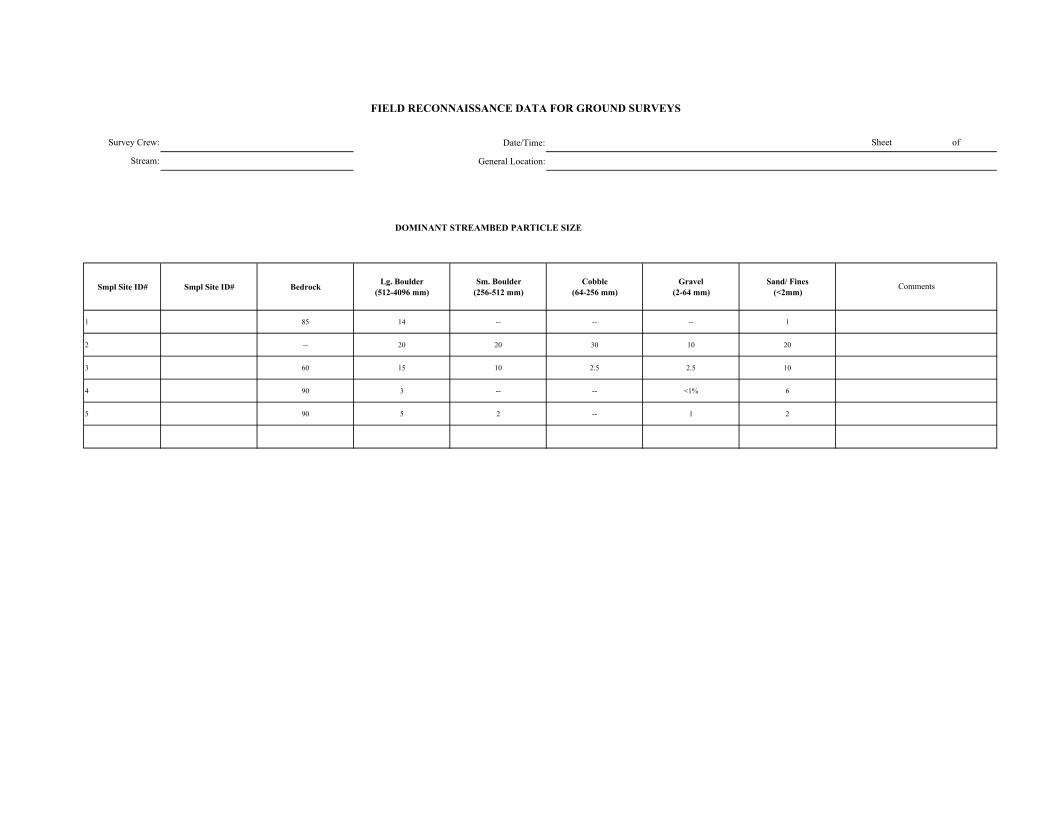
Date/Time:
General Location:
DOMINANT STREAMBED PARTICLE SIZE
Smpl Site ID# Smpl Site ID# Bedrock Lg. Boulder (512-4096 mm)
Sm. Boulder (256-512 mm)
Cobble (64-256 mm)
Gravel (2-64 mm)
Sand/ Fines (<2mm)
1 85 14 -- -- -- 1
2 -- 20 20 30 10 20
3 60 15 10 2.5 2.5 10
4 90 3 -- -- <1% 6
5 90 5 2 -- 1 2
FIELD RECONNAISSANCE DATA FOR GROUND SURVEYS
Sheet of
Comments
Survey Crew:
Stream:
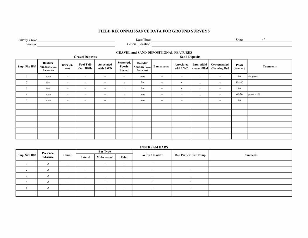
Survey Crew:Stream:
Smpl Site ID# Boulder
Shadow (none, few, many)
Bars (# in unit)
Pool Tail-Out/ Riffle
Associated with LWD
Scattered, Poorly Sorted
Boulder Shadow (none,
few, many)Bars (# in unit)
Associated with LWD
Interstitial spaces filled
Concentrated, Covering Bed
Pools (% on bed)
Comments
1 none -- -- -- -- none -- -- x -- 80 No gravel
2 few -- -- -- x few -- x x -- 80-100
3 few -- -- -- x few -- x x -- 80
4 none -- -- -- x none -- -- x -- 60-70 gravel <1%
5 none -- -- -- x none -- -- x -- 80
Lateral Mid-channel Point
1 A -- -- -- --
2 A -- -- -- --
3 A -- -- -- --
4 A -- -- -- --
5 A -- -- -- --
Comments
Sand Deposits
INSTREAM BARS
Presence/ Absence Count Active / Inactive Bar Particle Size Comp
Bar Type
FIELD RECONNAISSANCE DATA FOR GROUND SURVEYS
Date/Time:General Location:
Sheet of
GRAVEL and SAND DEPOSITIONAL FEATURESGravel Deposits
Smpl Site ID#
--
--
--
--
----
--
--
--
--

Survey Crew: Date/Time: Sheet of
Stream: General Location:
Vegetation in Bankfull Channel
POSTION TYPE SIZE CLASS
1 A -- -- -- 1 --
2 A -- -- -- 1 --
3 A -- -- -- 1 --
4 A -- -- -- 1 --
5 A -- -- -- 1 -- very little rip veg - some permininal herb/ alder (1/2/3) in FP area
very little rip veg - some permininal herb/ alder (1/2/3) in FP area 20%unit
very little rip veg - some permininal herb/ alder (1/2/3) in FP area
Interspersed alder and willow on channel margin; size class 1/2/3 (above Bf although indicators poor)
very little rip veg - some permininal herb/ alder (1/2/3) in Flood Plain area
Comments
VEGETATION ENCROACHMENT
FIELD RECONNAISSANCE DATA FOR GROUND SURVEYS
Smpl Site ID# VEG w/in BF
channel (P/A)
Vegetation Encroachment Rating
Veg Sz. Cl. in Relict BF Ch.
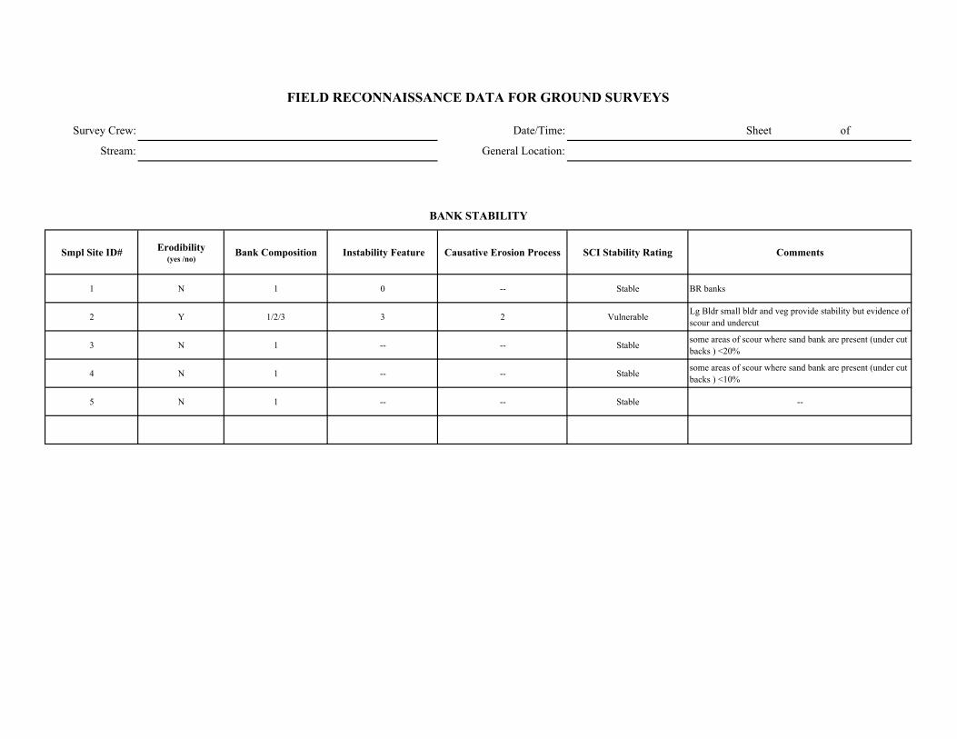
Survey Crew: Date/Time: Sheet of
Stream: General Location:
Smpl Site ID# Erodibility (yes /no)
Bank Composition Instability Feature Causative Erosion Process SCI Stability Rating Comments
1 N 1 0 -- Stable BR banks
2 Y 1/2/3 3 2 Vulnerable Lg Bldr small bldr and veg provide stability but evidence of scour and undercut
3 N 1 -- -- Stable some areas of scour where sand bank are present (under cut backs ) <20%
4 N 1 -- -- Stable some areas of scour where sand bank are present (under cut backs ) <10%
5 N 1 -- -- Stable --
FIELD RECONNAISSANCE DATA FOR GROUND SURVEYS
BANK STABILITY
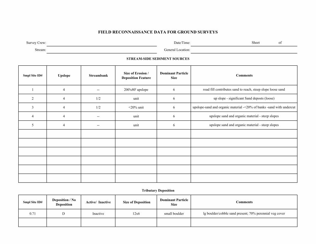
Survey Crew: Date/Time:
Stream: General Location:
Smpl Site ID# Upslope Streambank Size of Erosion / Deposition Feature
Dominant Particle Size
1 4 -- 200'x80' upslope 6
2 4 1/2 unit 6
3 4 1/2 <20% unit 6
4 4 -- unit 6
5 4 -- unit 6
Smpl Site ID# Deposition / No Deposition Active/ Inactive Size of Deposition Dominant Particle
Size
0.71 D Inactive 12x6 small boulder
Sheet of
FIELD RECONNAISSANCE DATA FOR GROUND SURVEYS
Comments
Tributary Deposition
STREAM-SIDE SEDIMENT SOURCES
Comments
road fill contributes sand to reach, steep slope loose sand
up slope - significant Sand deposts (loose)
upslope-sand and organic material -<20% of banks -sand with undercut
upslope sand and organic material - steep slopes
upslope sand and organic material - steep slopes
lg boulder/cobble sand present; 70% perennial veg cover
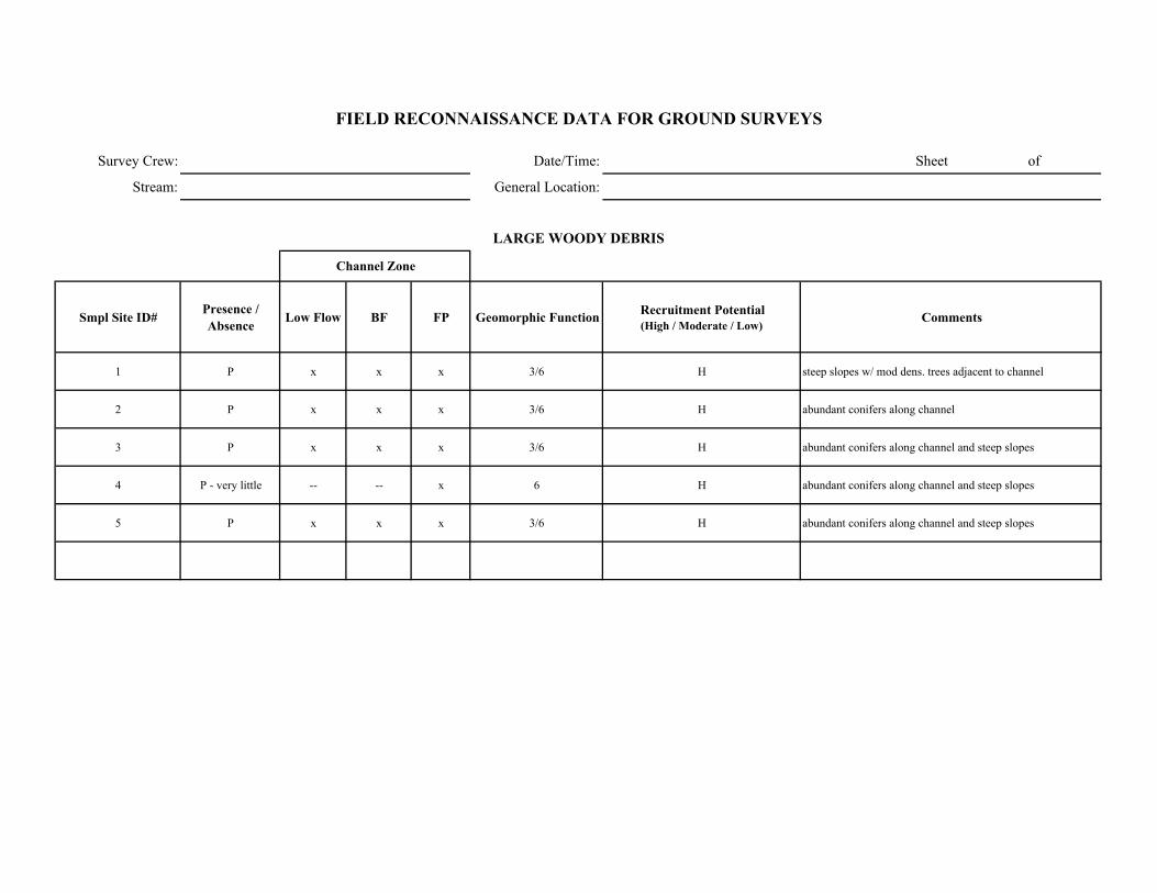
Survey Crew: Date/Time: Sheet of
Stream: General Location:
Smpl Site ID# Presence / Absence Low Flow BF FP Geomorphic Function Recruitment Potential
(High / Moderate / Low)Comments
1 P x x x 3/6 H steep slopes w/ mod dens. trees adjacent to channel
2 P x x x 3/6 H abundant conifers along channel
3 P x x x 3/6 H abundant conifers along channel and steep slopes
4 P - very little -- -- x 6 H abundant conifers along channel and steep slopes
5 P x x x 3/6 H abundant conifers along channel and steep slopes
FIELD RECONNAISSANCE DATA FOR GROUND SURVEYS
LARGE WOODY DEBRIS
Channel Zone
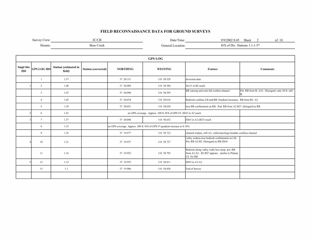
Date/Time: 9/9/2002 8:45 Sheet 2 of 10
General Location:
Smpl Site ID# GPS LOG ID# Station (estimated in
field) Station (corrected) NORTHING WESTING Feature Comments
1 1.57 37 20.151 118 58.529 diversion dam
1 2 1.48 37 20.089 118 58.584 SS #1 in B2 reach
3 1.47 37 20.090 118 58.595BR outcrop and rock fall confine channel Pot. RB from B- A/G. Disregard- only 50 ft- still
B
4 1.43 37 20.074 118 58.616 Bedrock confines LB and RB. Gradient increases. RB from B2- A2
5 1.39 37 20.051 118 58.638 lose BR confinement on RB. Pod. RB from A2-B2?- disregard no RB
2 6 1.41 no GPS coverage. Approx. 100 ft. D/S of GPS #5- SS#2 in A2 reach
3 7 1.37 37 20.048 118 58.652 SS#3 in A2 (B2?) reach
8 1.33 no GPS coverage. Approx. 200 ft. D/S of GPS #7-gradient increase to 8-10%
9 1.25 37 19.977 118 58.732 channel widens, still A2- colluvium/large boulder confines channel
4 10 1.21 37 19.937 118 58.737valley widens-lose bedrock confinement on LB- Pot. RB A2-B2. Disregard no RB SS#4
11 1.16 37 19.952 118 58.793Bedrock along valley walls less steep- pot. RB from A1/A2 - B1/B2? appears. similar to Pitman Ck. No RB.
5 12 1.12 37 19.955 118 58.811 SS#5 in A1/A2
13 1.1 37 19.986 118 58.858 End of Survey
GPS LOG
Survey Crew:
Stream:
FIELD RECONNAISSANCE DATA FOR GROUND SURVEYS
JC/CB
Bear Creek D/S of Div. Stations 1.1-1.57
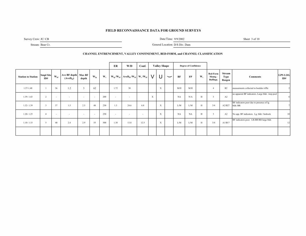
Survey Crew: JC/ CB 9/9/2002 Sheet 3 of 10
Stream: Bear Cr. D/S Div. Dam
ER W/D Conf.
Station to Station Smpl Site ID#
WbfAve BF depth
(AveDbf)Max BF
depthWfp Wv Wfp /Wbf AveDbf /Wbf Wv /Wbf V U ( BF FP Wv
Bed-Form Montg.-Buffingt.
Stream Type
RosgenComments GPS LOG
ID#
1.57-1.48 1 36 1.2 3 62 1.72 30 X M/H M/H 4 B2 measurments collected in boulder riffle 2
1.39- 1.43 2 - - - - 200 - - X NA N/A H 3 A2no apparent BF indicators. Large bldr. /step pool
6
1.32- 1.39 3 37 1.5 2.5 48 250 1.3 24.6 6.8 X L/M L/M H 3/4 A2/B2?BF indicators poor due to presence of lg. bldr./BR 7
1.20- 1.25 4 - - - - 250 - - - X NA NA H 3 A2 No app. BF indicators. Lg. bldr./ bedrock 10
1.10- 1.15 5 40 2.4 2.9 55 500 1.38 13.8 12.5 X L/M L/M H 3/4 A1/B1?BF indicators poor. LB-BR/RB large bldr.
12
FIELD RECONNAISSANCE DATA FOR GROUND SURVEYS
Degree of Confidence
CHANNEL ENTRENCHMENT, VALLEY CONFINEMENT, BED-FORM, and CHANNEL CLASSIFICATION
Valley Shape
Date/Time:
General Location:

JC/ CB Date/Time: 9/9/2002
Bear Creek General Location: D/S of div.
DOMINANT STREAMBED PARTICLE SIZE
Smpl Site ID# Smpl Site ID# Bedrock Lg. Boulder (512-4096 mm)
Sm. Boulder (256-512 mm)
Cobble (64-256 mm)
Gravel (2-64 mm)
Sand/ Fines (<2mm)
1 1 15 30 30 20 4 <1
2 2 15 60 15 7 3 <1
3 3 15 60 15 7 3 <1
4 4 10 55 15 10 10 <1
5 5 60 15 15 5 5 <1
Survey Crew:
Stream:
FIELD RECONNAISSANCE DATA FOR GROUND SURVEYS
sheet 4 of 10
Comments
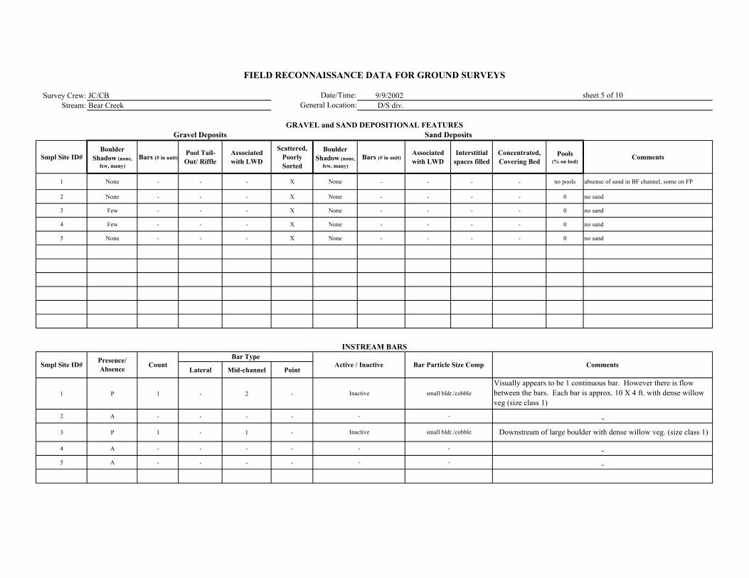
Survey Crew: JC/CB 9/9/2002Stream: Bear Creek D/S div.
Smpl Site ID# Boulder
Shadow (none, few, many)
Bars (# in unit)Pool Tail-Out/ Riffle
Associated with LWD
Scattered, Poorly Sorted
Boulder Shadow (none,
few, many)Bars (# in unit)
Associated with LWD
Interstitial spaces filled
Concentrated, Covering Bed
Pools (% on bed)
Comments
1 None - - - X None - - - - no pools absense of sand in BF channel, some on FP
2 None - - - X None - - - - 0 no sand
3 Few - - - X None - - - - 0 no sand
4 Few - - - X None - - - - 0 no sand
5 None - - - X None - - - - 0 no sand
Lateral Mid-channel Point
1 P 1 - 2 -
2 A - - - -
3 P 1 - 1 -
4 A - - - -
5 A - - - -
Inactive
-
Inactive
-
-
small bldr./cobble
-
small bldr./cobble
-
-
Visually appears to be 1 continuous bar. However there is flow between the bars. Each bar is approx. 10 X 4 ft. with dense willow veg (size class 1)
-
Downstream of large boulder with dense willow veg. (size class 1)
-
-
FIELD RECONNAISSANCE DATA FOR GROUND SURVEYS
Date/Time:General Location:
sheet 5 of 10
GRAVEL and SAND DEPOSITIONAL FEATURESGravel Deposits
Smpl Site ID# Comments
Sand Deposits
INSTREAM BARS
Presence/ Absence Count Active / Inactive Bar Particle Size Comp
Bar Type
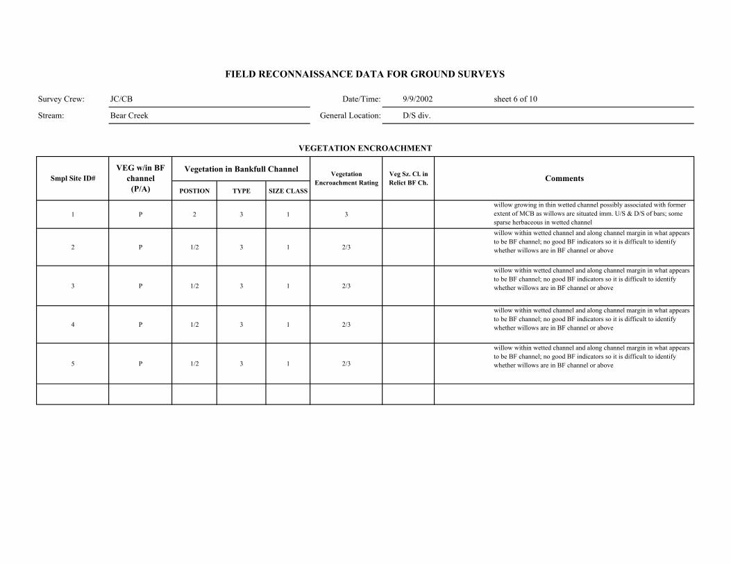
Survey Crew: JC/CB Date/Time: 9/9/2002 sheet 6 of 10
Stream: Bear Creek General Location: D/S div.
Vegetation in Bankfull Channel
POSTION TYPE SIZE CLASS
1 P 2 3 1 3willow growing in thin wetted channel possibly associated with former extent of MCB as willows are situated imm. U/S & D/S of bars; some sparse herbaceous in wetted channel
2 P 1/2 3 1 2/3
willow within wetted channel and along channel margin in what appears to be BF channel; no good BF indicators so it is difficult to identify whether willows are in BF channel or above
3 P 1/2 3 1 2/3
willow within wetted channel and along channel margin in what appears to be BF channel; no good BF indicators so it is difficult to identify whether willows are in BF channel or above
4 P 1/2 3 1 2/3
willow within wetted channel and along channel margin in what appears to be BF channel; no good BF indicators so it is difficult to identify whether willows are in BF channel or above
5 P 1/2 3 1 2/3
willow within wetted channel and along channel margin in what appears to be BF channel; no good BF indicators so it is difficult to identify whether willows are in BF channel or above
Comments
VEGETATION ENCROACHMENT
FIELD RECONNAISSANCE DATA FOR GROUND SURVEYS
Smpl Site ID# VEG w/in BF
channel (P/A)
Vegetation Encroachment Rating
Veg Sz. Cl. in Relict BF Ch.
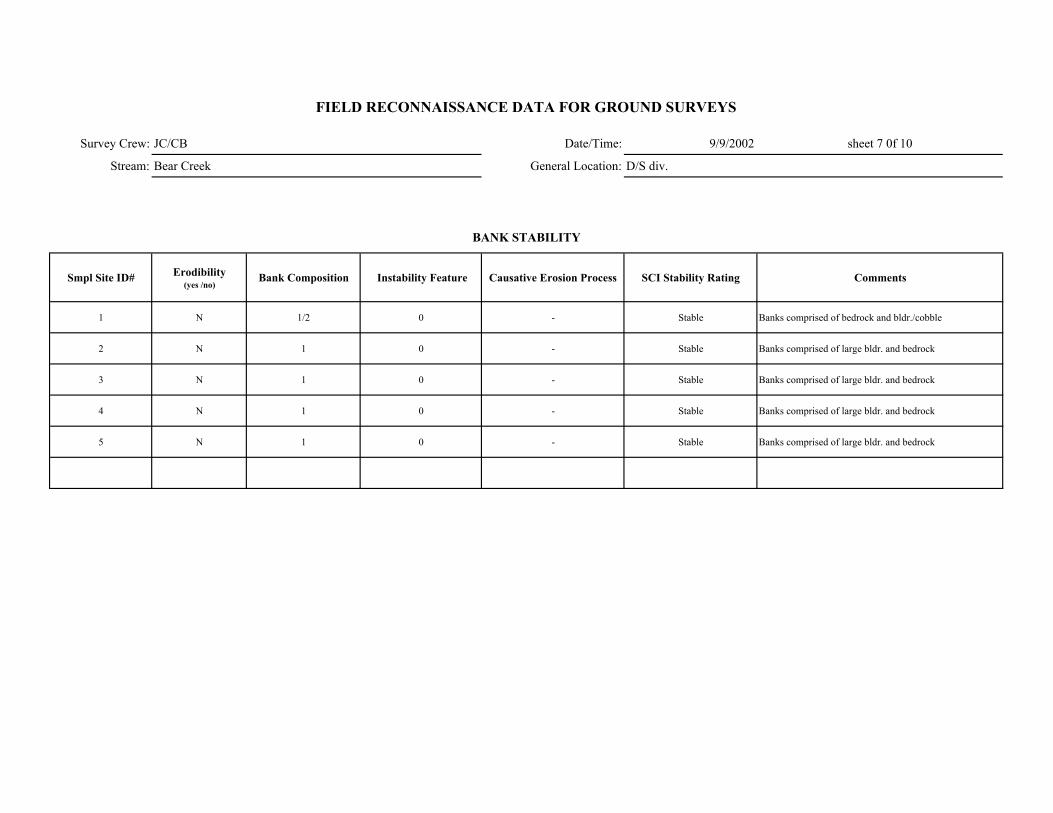
Survey Crew: JC/CB Date/Time: 9/9/2002 sheet 7 0f 10
Stream: Bear Creek General Location: D/S div.
Smpl Site ID# Erodibility (yes /no)
Bank Composition Instability Feature Causative Erosion Process SCI Stability Rating Comments
1 N 1/2 0 - Stable Banks comprised of bedrock and bldr./cobble
2 N 1 0 - Stable Banks comprised of large bldr. and bedrock
3 N 1 0 - Stable Banks comprised of large bldr. and bedrock
4 N 1 0 - Stable Banks comprised of large bldr. and bedrock
5 N 1 0 - Stable Banks comprised of large bldr. and bedrock
FIELD RECONNAISSANCE DATA FOR GROUND SURVEYS
BANK STABILITY
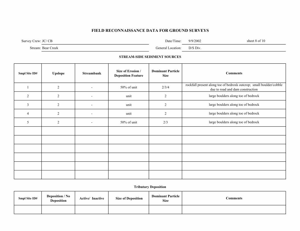
Survey Crew: JC/ CB Date/Time: 9/9/2002
Stream: Bear Creek General Location: D/S Div.
Smpl Site ID# Upslope Streambank Size of Erosion / Deposition Feature
Dominant Particle Size
1 2 - 50% of unit 2/3/4
2 2 - unit 2
3 2 - unit 2
4 2 - unit 2
5 2 - 50% of unit 2/3
Smpl Site ID# Deposition / No
Deposition Active/ Inactive Size of Deposition Dominant Particle Size
large boulders along toe of bedrock
sheet 8 of 10
FIELD RECONNAISSANCE DATA FOR GROUND SURVEYS
Comments
Tributary Deposition
STREAM-SIDE SEDIMENT SOURCES
Comments
rockfall present along toe of bedroxk outcrop; small boulder/cobble due to road and dam construction
large boulders along toe of bedrock
large boulders along toe of bedrock
large boulders along toe of bedrock
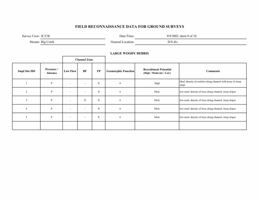
Survey Crew: JC/CB Date/Time: 9/9/2002 sheet 9 of 10
Stream: Big Creek General Location: D/S div.
Smpl Site ID# Presence / Absence Low Flow BF FP Geomorphic Function Recruitment Potential
(High / Moderate / Low)Comments
1 P - - X 6 High Mod. density of conifers along channel with areas of steep slope
2 P - - X 6 Mod. low-mod. dnesity of trees along channel, steep slopes
3 P - X X 6 Mod. low-mod. dnesity of trees along channel, steep slopes
4 P - - X 6 Mod. low-mod. dnesity of trees along channel, steep slopes
5 P - - X 6 Mod. low-mod. dnesity of trees along channel, steep slopes
FIELD RECONNAISSANCE DATA FOR GROUND SURVEYS
LARGE WOODY DEBRIS
Channel Zone
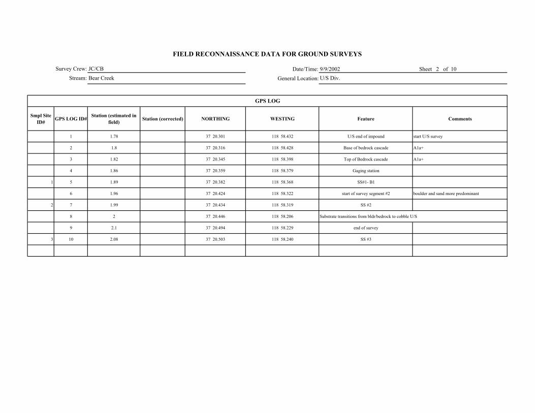
Date/Time: 9/9/2002 Sheet 2 of 10
General Location:
Smpl Site ID# GPS LOG ID# Station (estimated in
field) Station (corrected) NORTHING WESTING Feature Comments
1 1.78 37 20.301 118 58.432 U/S end of impound start U/S survey
2 1.8 37 20.316 118 58.428 Base of bedrock cascade A1a+
3 1.82 37 20.345 118 58.398 Top of Bedrock cascade A1a+
4 1.86 37 20.359 118 58.379 Gaging station
1 5 1.89 37 20.382 118 58.368 SS#1- B1
6 1.96 37 20.424 118 58.322 start of survey segment #2 boulder and sand more predominant
2 7 1.99 37 20.434 118 58.319 SS #2
8 2 37 20.446 118 58.206 Substrate transitions from bldr/bedrock to cobble U/S
9 2.1 37 20.494 118 58.229 end of survey
3 10 2.08 37 20.503 118 58.240 SS #3
GPS LOG
Survey Crew:
Stream:
FIELD RECONNAISSANCE DATA FOR GROUND SURVEYS
JC/CB
Bear Creek U/S Div.

Survey Crew: JC/CB 9/9/2002 sheet 3 of 10
Stream: Bear Cr. U/S div.
ER W/D Conf.
Station to Station Smpl Site ID#
WbfAve BF depth
(AveDbf)Max BF
depthWfp Wv Wfp /Wbf AveDbf /Wbf Wv /Wbf V U ( BF FP Wv
Bed-Form Montg.-Buffingt.
Stream Type Rosgen Comments GPS LOG
ID#
1.84- 1.90 1 56 0.6 1 65 1.16 93.3 X H H 4 B1 (F1?)BF- measurement in BR riffle at break in slope with fresh sand deposit on RB 5
1.96- 1.99 2 68 0.7 1.8 81 1.2 97.1 X H H 4 B1/B2 (F1/F2?) 7
2.0- 2.10 3 56 1.3 1.8 75 1.33 43.1 X M M 4 B2/B3(F2/F3?) Evidence of recent flow in floodplain area.
10
FIELD RECONNAISSANCE DATA FOR GROUND SURVEYS
Degree of Confidence
CHANNEL ENTRENCHMENT, VALLEY CONFINEMENT, BED-FORM, and CHANNEL CLASSIFICATION
Valley Shape
Date/Time:
General Location:
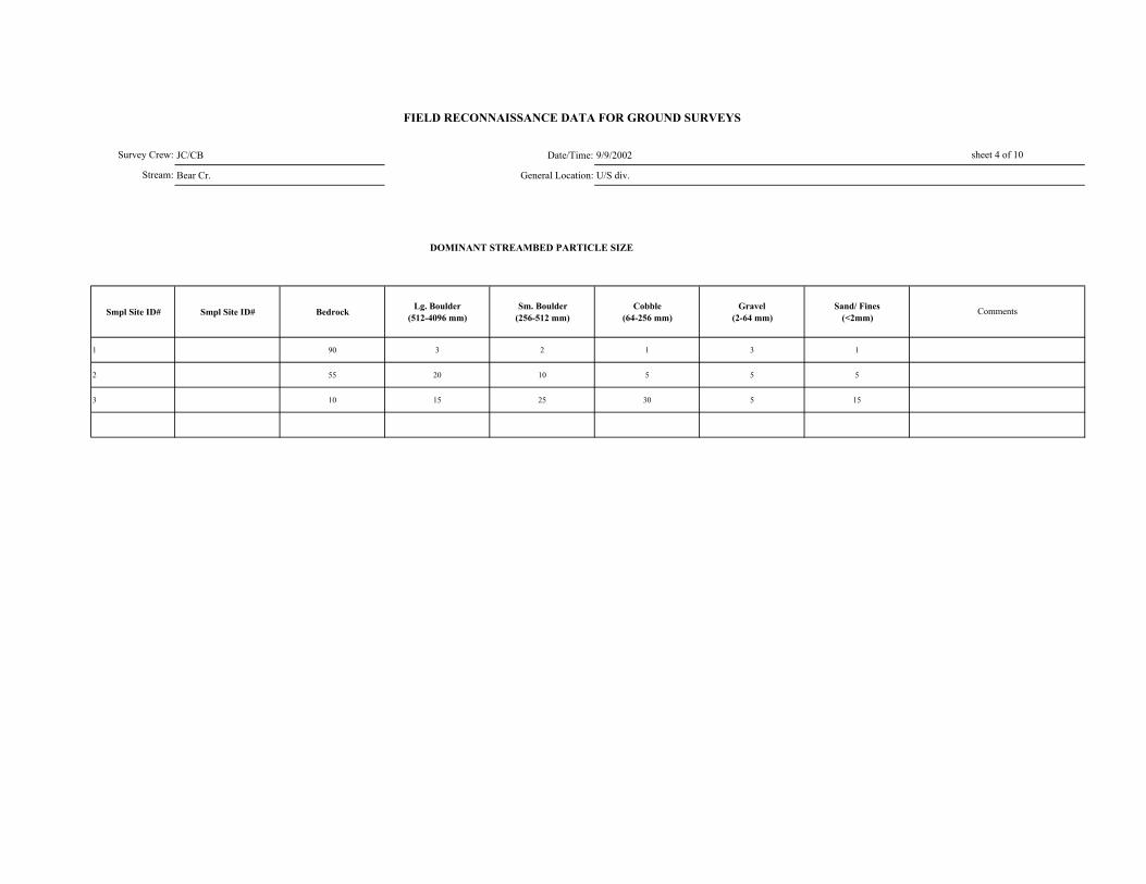
JC/CB Date/Time: 9/9/2002
Bear Cr. General Location: U/S div.
DOMINANT STREAMBED PARTICLE SIZE
Smpl Site ID# Smpl Site ID# Bedrock Lg. Boulder (512-4096 mm)
Sm. Boulder (256-512 mm)
Cobble (64-256 mm)
Gravel (2-64 mm)
Sand/ Fines (<2mm)
1 90 3 2 1 3 1
2 55 20 10 5 5 5
3 10 15 25 30 5 15
Survey Crew:
Stream:
FIELD RECONNAISSANCE DATA FOR GROUND SURVEYS
sheet 4 of 10
Comments
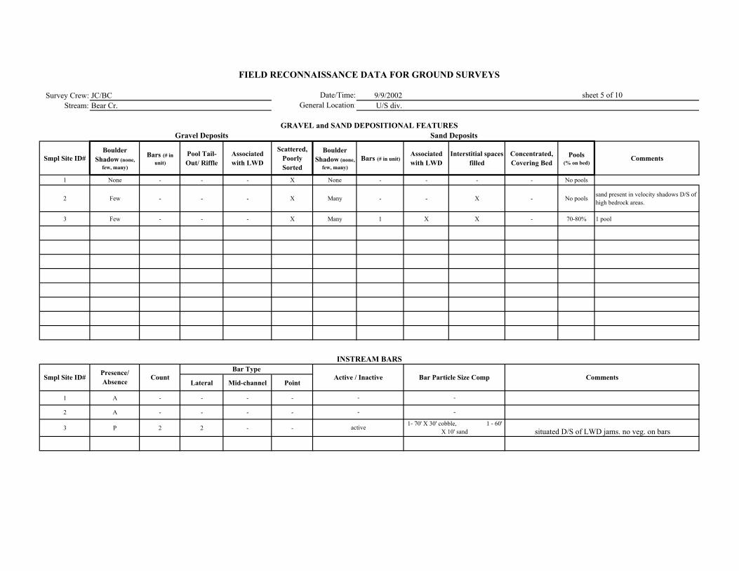
Survey Crew: JC/BC 9/9/2002Stream: Bear Cr. U/S div.
Smpl Site ID# Boulder
Shadow (none, few, many)
Bars (# in unit)
Pool Tail-Out/ Riffle
Associated with LWD
Scattered, Poorly Sorted
Boulder Shadow (none,
few, many)Bars (# in unit)
Associated with LWD
Interstitial spaces filled
Concentrated, Covering Bed
Pools (% on bed)
Comments
1 None - - - X None - - - - No pools
2 Few - - - X Many - - X - No pools sand present in velocity shadows D/S of high bedrock areas.
3 Few - - - X Many 1 X X - 70-80% 1 pool
Lateral Mid-channel Point
1 A - - - -
2 A - - - -
3 P 2 2 - -
-
-
active
-
-
1- 70' X 30' cobble, 1 - 60' X 10' sand situated D/S of LWD jams. no veg. on bars
FIELD RECONNAISSANCE DATA FOR GROUND SURVEYS
Date/Time:General Location:
sheet 5 of 10
GRAVEL and SAND DEPOSITIONAL FEATURESGravel Deposits
Smpl Site ID# Comments
Sand Deposits
INSTREAM BARS
Presence/ Absence Count Active / Inactive Bar Particle Size Comp
Bar Type
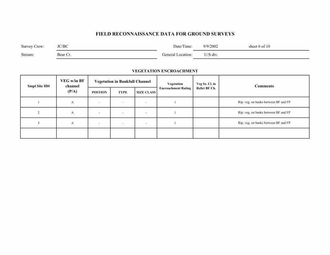
Survey Crew: JC/BC Date/Time: 9/9/2002 sheet 6 of 10
Stream: Bear Cr. General Location: U/S div.
Vegetation in Bankfull Channel
POSTION TYPE SIZE CLASS
1 A - - - 1
2 A - - - 1
3 A - - - 1
Rip. veg. on banks between BF and FP
Rip. veg. on banks between BF and FP
Rip. veg. on banks between BF and FP
Comments
VEGETATION ENCROACHMENT
FIELD RECONNAISSANCE DATA FOR GROUND SURVEYS
Smpl Site ID# VEG w/in BF
channel (P/A)
Vegetation Encroachment Rating
Veg Sz. Cl. in Relict BF Ch.
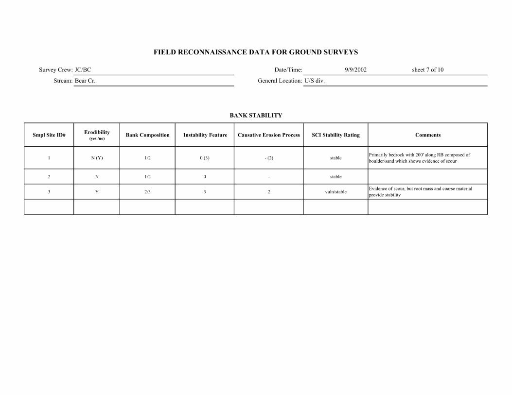
Survey Crew: JC/BC Date/Time: 9/9/2002 sheet 7 of 10
Stream: Bear Cr. General Location: U/S div.
Smpl Site ID# Erodibility (yes /no)
Bank Composition Instability Feature Causative Erosion Process SCI Stability Rating Comments
1 N (Y) 1/2 0 (3) - (2) stable Primarily bedrock with 200' along RB composed of boulder/sand which shows evidence of scour
2 N 1/2 0 - stable
3 Y 2/3 3 2 vuln/stable Evidence of scour, but root mass and coarse material provide stability
FIELD RECONNAISSANCE DATA FOR GROUND SURVEYS
BANK STABILITY
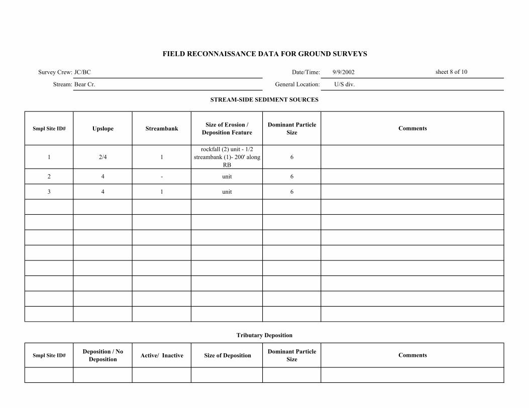
Survey Crew: JC/BC Date/Time: 9/9/2002
Stream: Bear Cr. General Location: U/S div.
Smpl Site ID# Upslope Streambank Size of Erosion / Deposition Feature
Dominant Particle Size
1 2/4 1rockfall (2) unit - 1/2
streambank (1)- 200' along RB
6
2 4 - unit 6
3 4 1 unit 6
Smpl Site ID# Deposition / No
Deposition Active/ Inactive Size of Deposition Dominant Particle Size
sheet 8 of 10
FIELD RECONNAISSANCE DATA FOR GROUND SURVEYS
Comments
Tributary Deposition
STREAM-SIDE SEDIMENT SOURCES
Comments
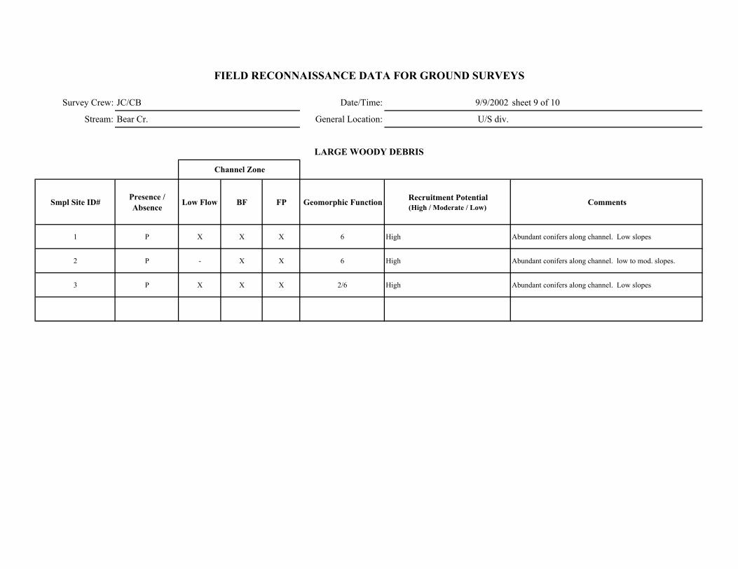
Survey Crew: JC/CB Date/Time: 9/9/2002 sheet 9 of 10
Stream: Bear Cr. General Location: U/S div.
Smpl Site ID# Presence / Absence Low Flow BF FP Geomorphic Function Recruitment Potential
(High / Moderate / Low)Comments
1 P X X X 6 High Abundant conifers along channel. Low slopes
2 P - X X 6 High Abundant conifers along channel. low to mod. slopes.
3 P X X X 2/6 High Abundant conifers along channel. Low slopes
FIELD RECONNAISSANCE DATA FOR GROUND SURVEYS
LARGE WOODY DEBRIS
Channel Zone
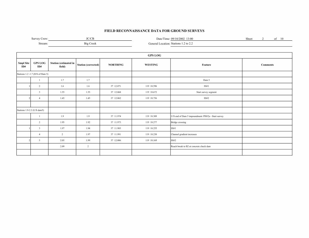
Date/Time: 09/10/2002 13:00 Sheet 2 of 10General Location:
Smpl Site ID#
GPS LOG ID#
Station (estimated in field) Station (corrected) NORTHING WESTING Feature Comments
Stations 1.2 -1.7 (D/S of Dam 5)
1 1.7 1.7 Dam 5
1 2 1.6 1.6 37 12.071 119 18.596 SS#1
3 1.55 1.55 37 12.068 119 18.672 Start survey segment
2 4 1.45 1.45 37 12.062 119 18.756 SS#2
Stations 1.9-2.2 (U/S dam5)
1 1.9 1.9 37 11.974 119 18.309 U/S end of Dam 5 impoundment /PH#2a - Start survey
2 1.95 1.92 37 11.973 119 18.277 Bridge crossing
1 3 1.97 1.94 37 11.983 119 18.255 SS#1
4 2 1.97 37 11.991 119 18.230 Channel gradient increases
2 5 2.05 1.99 37 12.006 119 18.169 SS#2
2.09 2 Reach break to B2 at concrete check dam
GPS LOG
Survey Crew:Stream:
FIELD RECONNAISSANCE DATA FOR GROUND SURVEYS
JC/CBBig Creek Stations 1.2 to 2.2
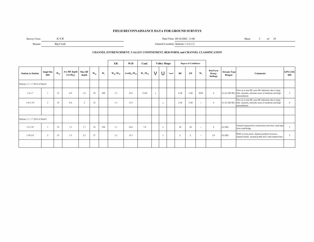
Survey Crew: 09/10/2002 13:00 Sheet 3 of 10
Stream:
ER W/D Conf.
Station to Station Smpl Site ID#
WbfAve BF depth
(AveDbf)Max BF
depthWfp Wv Wfp /Wbf AveDbf /Wbf Wv /Wbf V U ( BF FP Wv
Bed-Form Montg.-Buffingt.
Stream Type Rosgen Comments GPS LOG
ID#
Stations 1.2 -1.7 (D/S of Dam5)
1.6-1.7 1 23 0.9 1.6 30 300 1.3 25.6 13.04 x L/M L/M M/H 4 A1/A2 (B1/B2)Flow at or near BF, poor BF indicators due to large bldr. elements, alternate areas of moderate and high entrenchment.
2
1.45-1.55 2 25 0.8 2 32 1.3 12.5 x L/M L/M -- 4 A1/A2 (B1/B2)Flow at or near BF, poor BF indicators due to large bldr. elements, alternate areas of moderate and high entrenchment.
4
Stations 1.2 -1.7 (D/S of Dam5)
1.9-1.95 1 32 1.3 1.7 34 250 1.1 24.6 7.8 x M M -- 4 A2 (B2)Channel impacted by construction activities, sand inputfrom road/bridge 3
1.95-2.0 2 23 1.5 2.2 27 1.2 15.3 x L L -- 2/4 A2 (B2)HGR w/some pools, channel gradient increases, channel braids around lg bldr and 2 mid-channel bars 5
FIELD RECONNAISSANCE DATA FOR GROUND SURVEYS
Degree of Confidence
CHANNEL ENTRENCHMENT, VALLEY CONFINEMENT, BED-FORM, and CHANNEL CLASSIFICATION
Valley Shape
Date/Time:
General Location:
JC/CB
Big Creek Stations 1.2 to 2.2

JC/CB Date/Time: 09/10/2002 13:00
Big Creek General Location:
DOMINANT STREAMBED PARTICLE SIZE
Smpl Site ID# Smpl Site ID# Bedrock Lg. Boulder (512-4096 mm)
Sm. Boulder (256-512 mm)
Cobble (64-256 mm)
Gravel (2-64 mm)
Sand/ Fines (<2mm)
Stations 1.2 -1.7 (D/S of Dam5)
1 45 20 25 5 4 1
2 50 20 20 5 4 1
Stations 1.2 -1.7 (D/S of Dam5)
1 -- 30 40 10 10 10
2 10 50 30 5 3 2
Stations 1.2 to 2.2
Survey Crew:
Stream:
FIELD RECONNAISSANCE DATA FOR GROUND SURVEYS
Sheet 4 of 10
Comments

Survey Crew: JC/CB 09/10/2002 13:00Stream: Big Creek
Smpl Site ID# Boulder
Shadow (none, few, many)
Bars (# in unit)
Pool Tail-Out/ Riffle
Associated with LWD
Scattered, Poorly Sorted
Boulder Shadow (none,
few, many)Bars (# in unit)
Associated with LWD
Interstitial spaces filled
Concentrated, Covering Bed
Pools (% on bed)
Comments
Stations 1.2 -1.7 (D/S of Dam5)
1 none -- -- -- x none -- -- -- -- <10 very little to no sand
2 few -- -- -- x none -- -- -- -- <10 very little to no sand
Stations 1.2 -1.7 (D/S of Dam5)
1 few -- -- -- x few -- -- x -- 20-30
2 few -- -- -- x none -- -- x -- 20-30
Lateral Mid-channel Point
Stations 1.2 -1.7 (D/S of Dam5)
1 A -- -- -- --
2 P 1 -- 1 --
Stations 1.2 -1.7 (D/S of Dam5)
1 A -- -- -- --
2 P 2 -- 2 --
--
Inactive
--
Inactive
--
Large and small boulder
--
Large boulder
size- 50' x 20' with 50% veg. cover
sizes- 20'x5' & 80' x 50' with 75% veg. cover
FIELD RECONNAISSANCE DATA FOR GROUND SURVEYS
Date/Time:General Location:
Sheet 5 of 10
GRAVEL and SAND DEPOSITIONAL FEATURESGravel Deposits
Smpl Site ID#
Stations 1.2 to 2.2
Comments
Sand Deposits
INSTREAM BARS
Presence/ Absence Count Active / Inactive Bar Particle Size Comp
Bar Type
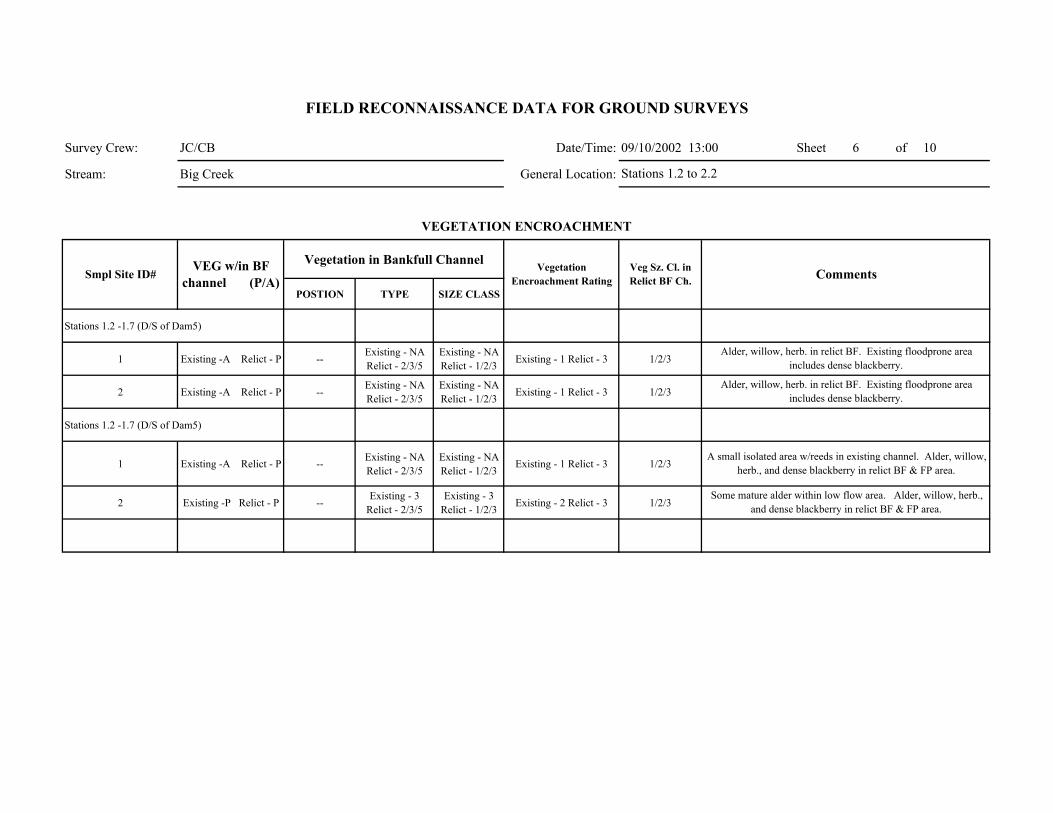
Survey Crew: JC/CB Date/Time: 09/10/2002 13:00 Sheet 6 of 10
Stream: Big Creek General Location:
Vegetation in Bankfull Channel
POSTION TYPE SIZE CLASS
Stations 1.2 -1.7 (D/S of Dam5)
1 Existing -A Relict - P --Existing - NA Relict - 2/3/5
Existing - NA Relict - 1/2/3 Existing - 1 Relict - 3 1/2/3
2 Existing -A Relict - P --Existing - NA Relict - 2/3/5
Existing - NA Relict - 1/2/3 Existing - 1 Relict - 3 1/2/3
Stations 1.2 -1.7 (D/S of Dam5)
1 Existing -A Relict - P -- Existing - NA Relict - 2/3/5
Existing - NA Relict - 1/2/3
Existing - 1 Relict - 3 1/2/3
2 Existing -P Relict - P --Existing - 3
Relict - 2/3/5Existing - 3
Relict - 1/2/3 Existing - 2 Relict - 3 1/2/3
Comments
VEGETATION ENCROACHMENT
FIELD RECONNAISSANCE DATA FOR GROUND SURVEYS
Smpl Site ID# VEG w/in BF
channel (P/A)Vegetation
Encroachment RatingVeg Sz. Cl. in Relict BF Ch.
Stations 1.2 to 2.2
Alder, willow, herb. in relict BF. Existing floodprone area includes dense blackberry.
Alder, willow, herb. in relict BF. Existing floodprone area includes dense blackberry.
A small isolated area w/reeds in existing channel. Alder, willow, herb., and dense blackberry in relict BF & FP area.
Some mature alder within low flow area. Alder, willow, herb., and dense blackberry in relict BF & FP area.
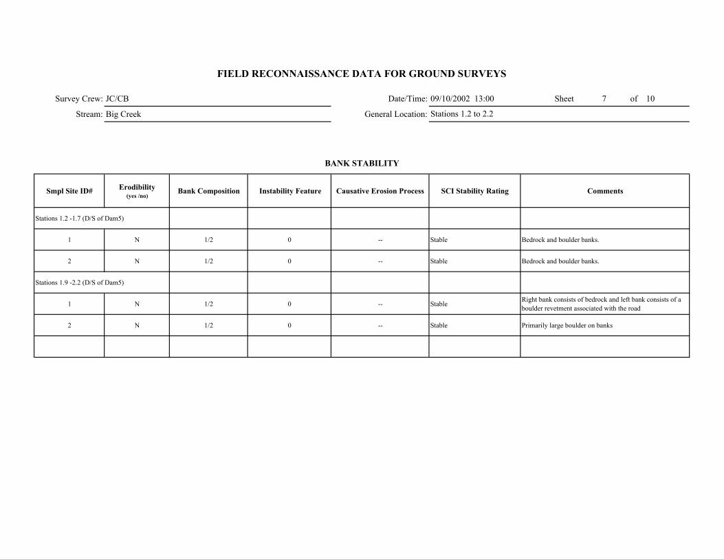
Survey Crew: JC/CB Date/Time: 09/10/2002 13:00 Sheet 7 of 10
Stream: Big Creek General Location:
Smpl Site ID# Erodibility (yes /no)
Bank Composition Instability Feature Causative Erosion Process SCI Stability Rating Comments
Stations 1.2 -1.7 (D/S of Dam5)
1 N 1/2 0 -- Stable Bedrock and boulder banks.
2 N 1/2 0 -- Stable Bedrock and boulder banks.
Stations 1.9 -2.2 (D/S of Dam5)
1 N 1/2 0 -- Stable Right bank consists of bedrock and left bank consists of a boulder revetment associated with the road
2 N 1/2 0 -- Stable Primarily large boulder on banks
FIELD RECONNAISSANCE DATA FOR GROUND SURVEYS
BANK STABILITY
Stations 1.2 to 2.2
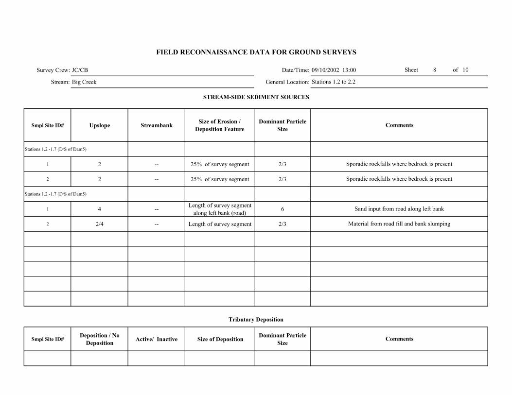
Survey Crew: JC/CB Date/Time: 09/10/2002 13:00
Stream: Big Creek General Location:
Smpl Site ID# Upslope Streambank Size of Erosion / Deposition Feature
Dominant Particle Size
Stations 1.2 -1.7 (D/S of Dam5)
1 2 -- 25% of survey segment 2/3
2 2 -- 25% of survey segment 2/3
Stations 1.2 -1.7 (D/S of Dam5)
1 4 -- Length of survey segment along left bank (road) 6
2 2/4 -- Length of survey segment 2/3
Smpl Site ID# Deposition / No
Deposition Active/ Inactive Size of Deposition Dominant Particle Size
Comments
Tributary Deposition
STREAM-SIDE SEDIMENT SOURCES
Comments
Sporadic rockfalls where bedrock is present
Sand input from road along left bank
Material from road fill and bank slumping
Stations 1.2 to 2.2
Sporadic rockfalls where bedrock is present
Sheet 8 of 10
FIELD RECONNAISSANCE DATA FOR GROUND SURVEYS
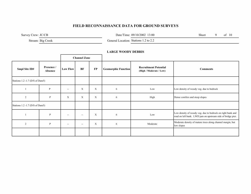
Survey Crew: JC/CB Date/Time: 09/10/2002 13:00 Sheet 9 of 10
Stream: Big Creek General Location:
Smpl Site ID# Presence / Absence Low Flow BF FP Geomorphic Function Recruitment Potential
(High / Moderate / Low)Comments
Stations 1.2 -1.7 (D/S of Dam5)
1 P -- X X 6 Low Low density of woody veg. due to bedrock
2 P X X X 6 High Dense conifers and steep slopes
Stations 1.2 -1.7 (D/S of Dam5)
1 P -- -- X 6 LowLow density of woody veg. due to bedrock on right bank and road on left bank. LWD jam on upstream side of bridge pier.
2 P -- -- X 6 Moderate Moderate density of mature trees along channel margin, but low slopes
FIELD RECONNAISSANCE DATA FOR GROUND SURVEYS
LARGE WOODY DEBRIS
Channel Zone
Stations 1.2 to 2.2
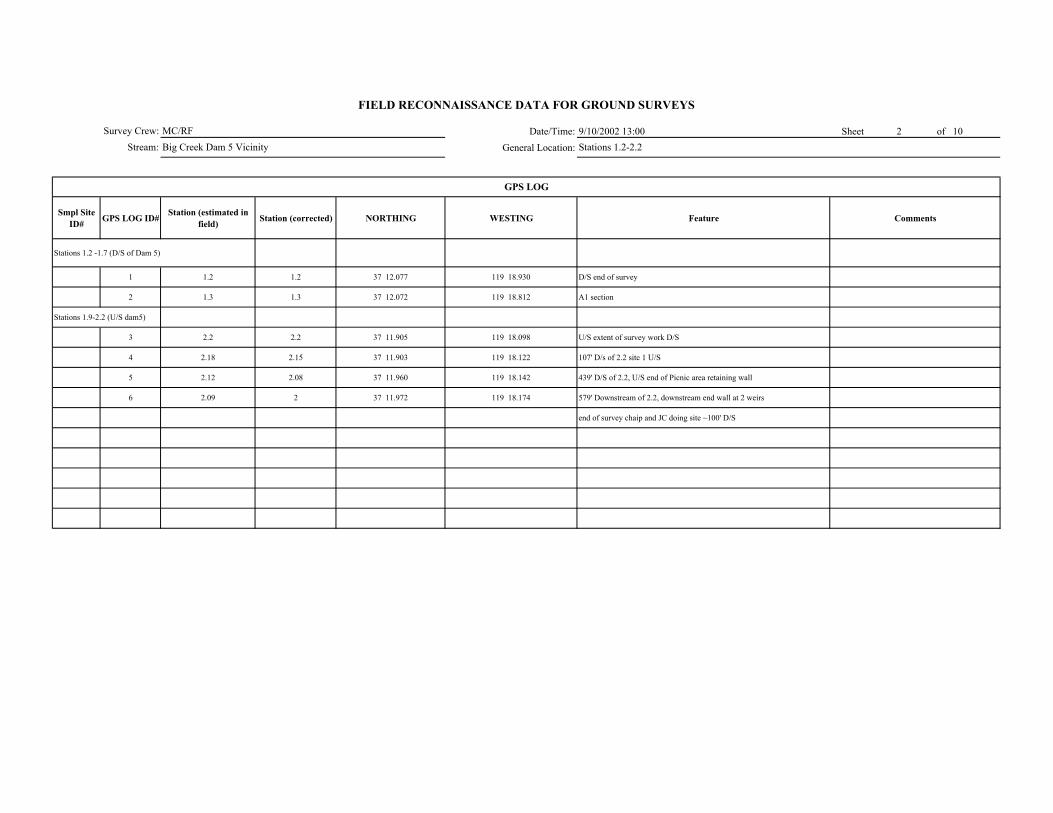
Date/Time: 9/10/2002 13:00 Sheet 2 of 10General Location:
Smpl Site ID# GPS LOG ID# Station (estimated in
field) Station (corrected) NORTHING WESTING Feature Comments
Stations 1.2 -1.7 (D/S of Dam 5)
1 1.2 1.2 37 12.077 119 18.930 D/S end of survey
2 1.3 1.3 37 12.072 119 18.812 A1 section
Stations 1.9-2.2 (U/S dam5)
3 2.2 2.2 37 11.905 119 18.098 U/S extent of survey work D/S
4 2.18 2.15 37 11.903 119 18.122 107' D/s of 2.2 site 1 U/S
5 2.12 2.08 37 11.960 119 18.142 439' D/S of 2.2, U/S end of Picnic area retaining wall
6 2.09 2 37 11.972 119 18.174 579' Downstream of 2.2, downstream end wall at 2 weirs
end of survey chaip and JC doing site ~100' D/S
GPS LOG
Survey Crew:Stream:
FIELD RECONNAISSANCE DATA FOR GROUND SURVEYS
MC/RFBig Creek Dam 5 Vicinity Stations 1.2-2.2

Survey Crew: ############ Sheet of
Stream:
ER W/D Conf.
Station to Station Smpl Site ID#
Wbf
Ave BF depth
(AveDbf)
Max BF depth
Wfp Wv Wfp /Wbf AveDbf /Wbf Wv /Wbf V U ( BF FP Wv
Bed-Form Montg.-Buffingt.
Stream Type Rosgen Comments GPS LOG
ID#
Stations 1.2 -1.7 (D/S of Dam 5)
1.2 1 21 1 2.2 28 1.33 21 x x L L -- 1/(4) A1/B1 (A2/B2) 1
Stations 1.9-2.2 (U/S dam5)
2.2-1.16 1U/S 21 0.9 1.3 31 1.47 23.3 x x L/M L/M -- 4 B2Bedrock banks with large boulder and large boulder pool control. Small boulder/cobble bed. 4
FIELD RECONNAISSANCE DATA FOR GROUND SURVEYS
Degree of Confidence
CHANNEL ENTRENCHMENT, VALLEY CONFINEMENT, BED-FORM, and CHANNEL CLASSIFICATION
Valley Shape
Date/Time:
General Location:
MC/RF
Big Creek Dam 5 Vicinity Stations 1.2-2.2
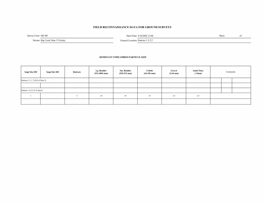
Date/Time: 9/10/2002 13:00
General Location:
DOMINANT STREAMBED PARTICLE SIZE
Smpl Site ID# Smpl Site ID# Bedrock Lg. Boulder (512-4096 mm)
Sm. Boulder (256-512 mm)
Cobble (64-256 mm)
Gravel (2-64 mm)
Sand/ Fines (<2mm)
Stations 1.2 -1.7 (D/S of Dam 5)
Stations 1.9-2.2 (U/S dam5)
1 5 20 45 25 2.5 2.5
MC/RF
Big Creek Dam 5 Vicinity Stations 1.2-2.2
Survey Crew:
Stream:
FIELD RECONNAISSANCE DATA FOR GROUND SURVEYS
Sheet of
Comments

Survey Crew: 9/10/2002 13:00Stream:
Smpl Site ID# Boulder
Shadow (none, few, many)
Bars (# in unit)
Pool Tail-Out/ Riffle
Associated with LWD
Scattered, Poorly Sorted
Boulder Shadow (none,
few, many)Bars (# in unit)
Associated with LWD
Interstitial spaces filled
Concentrated, Covering Bed
Pools (% on bed)
Comments
Stations 1.2 -1.7 (D/S of Dam 5) Stations 1.9-2.2 (U/S dam5)
1 U/S none 0 N N Y none 0 N Y (some) N 5
Lateral Mid-channel Point
Stations 1.9-2.2 (U/S dam5)
1 U/S A -- -- -- --
Stations 1.2-2.2MC/RFBig Creek Dam 5 Vicinity
-- --
FIELD RECONNAISSANCE DATA FOR GROUND SURVEYS
Date/Time:General Location:
Sheet of
GRAVEL and SAND DEPOSITIONAL FEATURESGravel Deposits
Smpl Site ID# Comments
Sand Deposits
INSTREAM BARS
Presence/ Absence Count Active / Inactive Bar Particle Size Comp
Bar Type
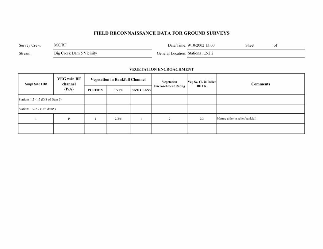
Survey Crew: Date/Time: 9/10/2002 13:00 Sheet of
Stream: General Location:
Vegetation in Bankfull Channel
POSTION TYPE SIZE CLASS
Stations 1.2 -1.7 (D/S of Dam 5)
Stations 1.9-2.2 (U/S dam5)
1 P 1 2/3/5 1 2 2/3 Mature alder in relict bankfull
Comments
VEGETATION ENCROACHMENT
FIELD RECONNAISSANCE DATA FOR GROUND SURVEYS
Smpl Site ID# VEG w/in BF
channel (P/A)
Vegetation Encroachment Rating
Veg Sz. Cl. in Relict BF Ch.
MC/RF
Big Creek Dam 5 Vicinity Stations 1.2-2.2

Survey Crew: Date/Time: 9/10/2002 13:00 Sheet of
Stream: General Location:
Smpl Site ID# Erodibility (yes /no)
Bank Composition Instability Feature Causative Erosion Process SCI Stability Rating Comments
Stations 1.2 -1.7 (D/S of Dam 5)
Stations 1.9-2.2 (U/S dam5)
1 N 1 (2) 0 2 Stable Bedrock and large/small boulder armor banks
FIELD RECONNAISSANCE DATA FOR GROUND SURVEYS
BANK STABILITY
MC/RF
Big Creek Dam 5 Vicinity Stations 1.2-2.2

Survey Crew: Date/Time: 9/10/2002 13:00
Stream: General Location:
Smpl Site ID# Upslope Streambank Size of Erosion / Deposition Feature
Dominant Particle Size
Stations 1.2 -1.7 (D/S of Dam 5)
Stations 1.9-2.2 (U/S dam5)
1 4 (if any) 1 (if any) <5% of survey segment Sand
Smpl Site ID# Deposition / No
Deposition Active/ Inactive Size of Deposition Dominant Particle Size
Sheet of
Big Creek Dam 5 Vicinity Stations 1.2-2.2
FIELD RECONNAISSANCE DATA FOR GROUND SURVEYS
Comments
Tributary Deposition
STREAM-SIDE SEDIMENT SOURCES
Comments
Not much erosion, no deposits
MC/RF

Survey Crew: Date/Time: 9/10/2002 13:00 Sheet of
Stream: General Location:
Smpl Site ID# Presence / Absence Low Flow BF FP Geomorphic Function Recruitment Potential
(High / Moderate / Low)Comments
Stations 1.2 -1.7 (D/S of Dam 5)
Stations 1.9-2.2 (U/S dam5)
1 U/S P x x 6 L Not much LWD and no function as the LWD stranded on banks
FIELD RECONNAISSANCE DATA FOR GROUND SURVEYS
LARGE WOODY DEBRIS
Channel Zone
MC/RF
Big Creek Dam 5 Vicinity Stations 1.2-2.2

Date/Time: 8/8/2002 9:15 Sheet of General Location:
Smpl Site ID# GPS LOG ID# Station (estimated in
field) Station (corrected) NORTHING WESTING Feature Comments
1 7.85 37 13.215 119 13.748 Start of survey in A1a+ channel1 2 7.9 37 13.173 119 13.649 SS#1 in A1a+ reach
3 7.92 37 13.165 119 13.627 Reach break from A1a+ (D/S) to B2 (U/S)
4 7.94 37 13.150 119 13.602
Rockfall (approx. 100' long & extending 150' upslope) consisting of large and small boulder extending to the channel with riparian veg. at channel margin (approx. 10 ft. wide).
2 5 7.96 37 13.169 119 13.582 SS#2
6 7.67 37 13.154 119 13.562
Rockfall (approx. 200' long & extending 200' upslope) consisting of large bldr. extending to channel with riparian veg. at channel margin (approx. 10 ft. wide)
7 8.05 37 13.168 119 13.496 Transition transition from B2 to B1 with A1 inclusions
8 8.06 37 13.144 119 13.480Rockfall(approx. 50' long & extending 100' upslope) consisting of large boulder extending to channel
3 9 8.13 37 13.130 119 13.418 SS#3 in B2
10 8.13 37 13.122 119 13.408Rock fall (approx. 50' long & extending 50' upslope) consisting of large boulder extending to channel
11 8.17 37 13.087 119 13.383Channel filled with large boulder (Avg. size 10' by 10') with flow within/under boulders. Dimensions of rockfall - approx. 200 feet long by 50 feet wide.
12 8.27 no gps no gps Possible reach break from B2 to C5 (B5?)
4a 13 8.3 37 13.122 119 13.254 SS#4a in C5 (B5?)4b 14 8.35 37 13.076 119 13.254 SS#4b in C5 (B5?)5 15 8.5 37 13.096 119 13.095 SS#5 in in C5 (B5?)
16 8.6 37 13.155 119 13.017 Possible RB from C5 (B5?) to ? - gradient increases
6a 17 8.65 37 13.171 119 12.992 SS#6a in C2/C5 (B2/B5?)6b 18 8.7 37 13.180 119 12.973 SS#6b in C2/C5 (B2/B5?)7 19 8.75 37 13.157 119 12.925 SS#7 in D2/D5 (C2/C5 or B2/B5?)
8 20 8.85 37 13.183 119 12.8.2 SS#8 and Reach break from D2/D5 (C2/C5 or B2/B5?) to A2
GPS LOG
Survey Crew:Stream:
FIELD RECONNAISSANCE DATA FOR GROUND SURVEYS
JC/CB Big Creek Station 7.9-9.9
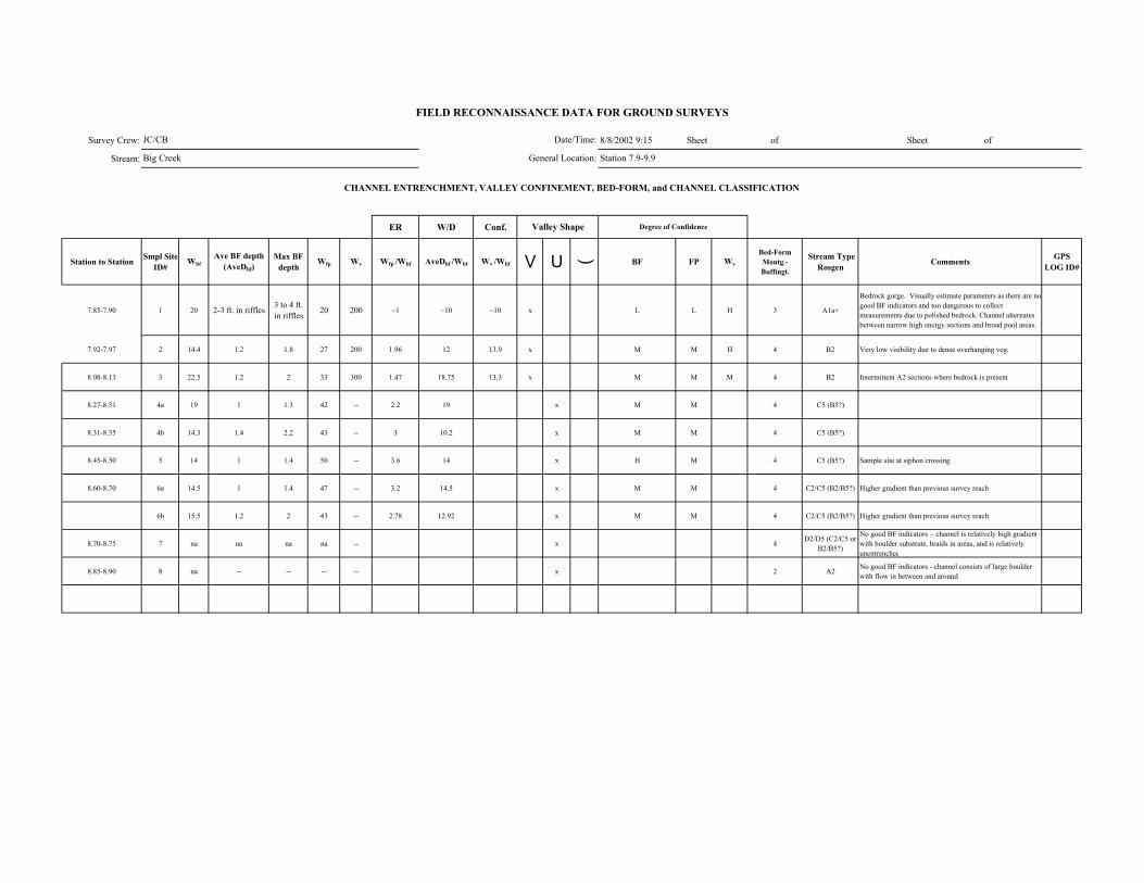
Survey Crew: 8/8/2002 9:15 Sheet of Sheet of
Stream:
ER W/D Conf.
Station to Station Smpl Site ID#
WbfAve BF depth
(AveDbf)Max BF
depthWfp Wv Wfp /Wbf AveDbf /Wbf Wv /Wbf V U ( BF FP Wv
Bed-Form Montg.-Buffingt.
Stream Type Rosgen Comments GPS
LOG ID#
7.85-7.90 1 20 2-3 ft. in riffles 3 to 4 ft. in riffles 20 200 ~1 ~10 ~10 x L L H 3 A1a+
Bedrock gorge. Visually estimate parameters as there are no good BF indicators and too dangerous to collect measurements due to polished bedrock. Channel alternates between narrow high energy sections and broad pool areas.
7.92-7.97 2 14.4 1.2 1.8 27 200 1.96 12 13.9 x M M H 4 B2 Very low visibility due to dense overhanging veg.
8.08-8.13 3 22.5 1.2 2 33 300 1.47 18.75 13.3 x M M M 4 B2 Intermittent A2 sections where bedrock is present
8.27-8.31 4a 19 1 1.3 42 -- 2.2 19 x M M 4 C5 (B5?)
8.31-8.35 4b 14.3 1.4 2.2 43 -- 3 10.2 x M M 4 C5 (B5?)
8.45-8.50 5 14 1 1.4 50 -- 3.6 14 x H M 4 C5 (B5?) Sample site at siphon crossing
8.60-8.70 6a 14.5 1 1.4 47 -- 3.2 14.5 x M M 4 C2/C5 (B2/B5?) Higher gradient than previous survey reach
6b 15.5 1.2 2 43 -- 2.78 12.92 x M M 4 C2/C5 (B2/B5?) Higher gradient than previous survey reach
8.70-8.75 7 na na na na -- x 4 D2/D5 (C2/C5 or B2/B5?)
No good BF indicators - channel is relatively high gradientwith boulder substrate, braids in areas, and is relatively unentrenched
8.85-8.90 8 na -- -- -- -- x 2 A2 No good BF indicators - channel consists of large boulder with flow in between and around
FIELD RECONNAISSANCE DATA FOR GROUND SURVEYS
Degree of Confidence
CHANNEL ENTRENCHMENT, VALLEY CONFINEMENT, BED-FORM, and CHANNEL CLASSIFICATION
Valley Shape
Date/Time:
General Location:
JC/CB
Big Creek Station 7.9-9.9
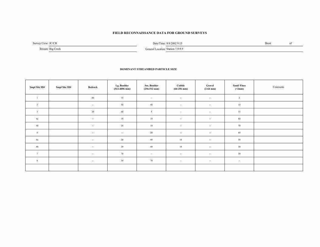
Date/Time: 8/8/2002 9:15
General Location:
DOMINANT STREAMBED PARTICLE SIZE
Smpl Site ID# Smpl Site ID# Bedrock Lg. Boulder (512-4096 mm)
Sm. Boulder (256-512 mm)
Cobble (64-256 mm)
Gravel (2-64 mm)
Sand/ Fines (<2mm)
1 80 15 -- -- -- 5
2 -- 50 40 -- -- 10
3 20 60 5 -- -- 15
4a -- 10 10 -- -- 80
4b -- 20 10 -- -- 70
5 -- -- 20 -- -- 80
6a -- 20 40 10 -- 30
6b -- 20 40 10 -- 30
7 -- 70 -- -- -- 30
8 -- 30 70 -- -- --
JC/CB
Big Creek Station 7.9-9.9
Survey Crew:
Stream:
FIELD RECONNAISSANCE DATA FOR GROUND SURVEYS
Sheet of
Comments
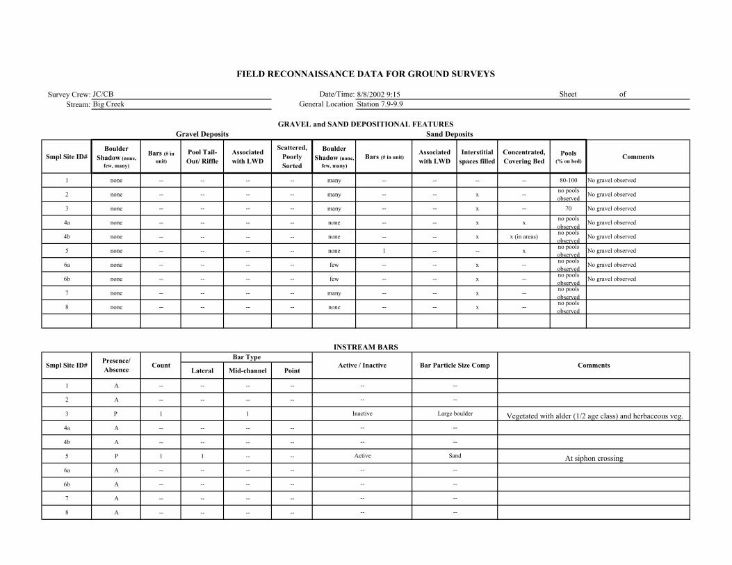
Survey Crew: 8/8/2002 9:15Stream:
Smpl Site ID# Boulder
Shadow (none, few, many)
Bars (# in unit)
Pool Tail-Out/ Riffle
Associated with LWD
Scattered, Poorly Sorted
Boulder Shadow (none,
few, many)Bars (# in unit)
Associated with LWD
Interstitial spaces filled
Concentrated, Covering Bed
Pools (% on bed)
Comments
1 none -- -- -- -- many -- -- -- -- 80-100 No gravel observed
2 none -- -- -- -- many -- -- x -- no pools observed
No gravel observed
3 none -- -- -- -- many -- -- x -- 70 No gravel observed
4a none -- -- -- -- none -- -- x x no pools observed
No gravel observed
4b none -- -- -- -- none -- -- x x (in areas) no pools observed
No gravel observed
5 none -- -- -- -- none 1 -- -- x no pools observed
No gravel observed
6a none -- -- -- -- few -- -- x -- no pools observed
No gravel observed
6b none -- -- -- -- few -- -- x -- no pools observed
No gravel observed
7 none -- -- -- -- many -- -- x -- no pools observed
8 none -- -- -- -- none -- -- x -- no pools observed
Lateral Mid-channel Point
1 A -- -- -- --
2 A -- -- -- --
3 P 1 1
4a A -- -- -- --
4b A -- -- -- --
5 P 1 1 -- --
6a A -- -- -- --
6b A -- -- -- --
7 A -- -- -- --
8 A -- -- -- --
JC/CB Big Creek Station 7.9-9.9
--
--
Inactive
--
--
Active
--
--
--
--
Sand
--
--
--
--
Large boulder
--
--
----
Vegetated with alder (1/2 age class) and herbaceous veg.
At siphon crossing
FIELD RECONNAISSANCE DATA FOR GROUND SURVEYS
Date/Time:General Location:
Sheet of
GRAVEL and SAND DEPOSITIONAL FEATURESGravel Deposits
Smpl Site ID# Comments
Sand Deposits
INSTREAM BARS
Presence/ Absence Count Active / Inactive Bar Particle Size Comp
Bar Type
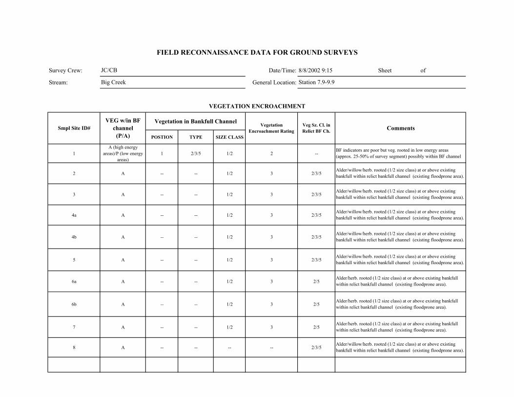
Survey Crew: Date/Time: 8/8/2002 9:15 Sheet of
Stream: General Location:
Vegetation in Bankfull Channel
POSTION TYPE SIZE CLASS
1A (high energy
areas)/P (low energy areas)
1 2/3/5 1/2 2 --
2 A -- -- 1/2 3 2/3/5
3 A -- -- 1/2 3 2/3/5
4a A -- -- 1/2 3 2/3/5
4b A -- -- 1/2 3 2/3/5
5 A -- -- 1/2 3 2/3/5
6a A -- -- 1/2 3 2/5
6b A -- -- 1/2 3 2/5
7 A -- -- 1/2 3 2/5
8 A -- -- -- -- 2/3/5
FIELD RECONNAISSANCE DATA FOR GROUND SURVEYS
Smpl Site ID# VEG w/in BF
channel (P/A)
Vegetation Encroachment Rating
Veg Sz. Cl. in Relict BF Ch.
JC/CB
Big Creek Station 7.9-9.9
BF indicators are poor but veg. rooted in low energy areas (approx. 25-50% of survey segment) possibly within BF channel
Alder/willow/herb. rooted (1/2 size class) at or above existing bankfull within relict bankfull channel (existing floodprone area).
Comments
VEGETATION ENCROACHMENT
Alder/herb. rooted (1/2 size class) at or above existing bankfull within relict bankfull channel (existing floodprone area).
Alder/willow/herb. rooted (1/2 size class) at or above existing bankfull within relict bankfull channel (existing floodprone area).
Alder/willow/herb. rooted (1/2 size class) at or above existing bankfull within relict bankfull channel (existing floodprone area).
Alder/willow/herb. rooted (1/2 size class) at or above existing bankfull within relict bankfull channel (existing floodprone area).
Alder/willow/herb. rooted (1/2 size class) at or above existing bankfull within relict bankfull channel (existing floodprone area).
Alder/willow/herb. rooted (1/2 size class) at or above existing bankfull within relict bankfull channel (existing floodprone area).
Alder/herb. rooted (1/2 size class) at or above existing bankfull within relict bankfull channel (existing floodprone area).
Alder/herb. rooted (1/2 size class) at or above existing bankfull within relict bankfull channel (existing floodprone area).
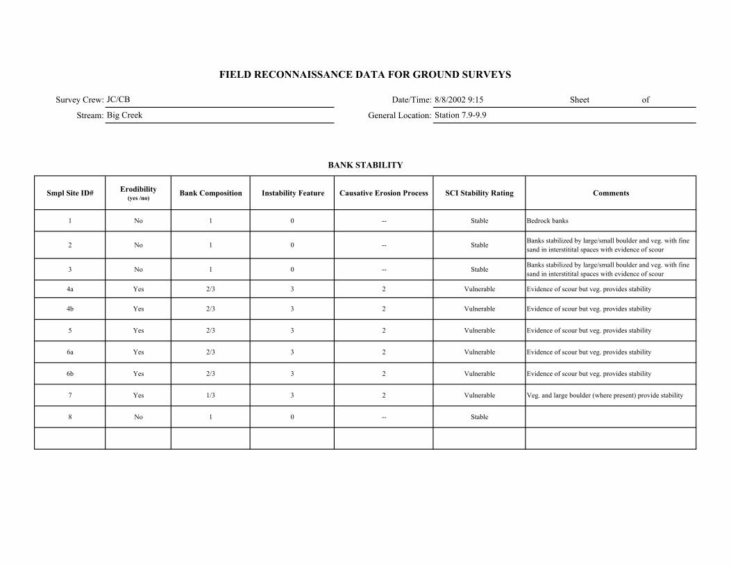
Survey Crew: Date/Time: 8/8/2002 9:15 Sheet of
Stream: General Location:
Smpl Site ID# Erodibility (yes /no)
Bank Composition Instability Feature Causative Erosion Process SCI Stability Rating Comments
1 No 1 0 -- Stable Bedrock banks
2 No 1 0 -- Stable Banks stabilized by large/small boulder and veg. with fine sand in interstitital spaces with evidence of scour
3 No 1 0 -- Stable Banks stabilized by large/small boulder and veg. with fine sand in interstitital spaces with evidence of scour
4a Yes 2/3 3 2 Vulnerable Evidence of scour but veg. provides stability
4b Yes 2/3 3 2 Vulnerable Evidence of scour but veg. provides stability
5 Yes 2/3 3 2 Vulnerable Evidence of scour but veg. provides stability
6a Yes 2/3 3 2 Vulnerable Evidence of scour but veg. provides stability
6b Yes 2/3 3 2 Vulnerable Evidence of scour but veg. provides stability
7 Yes 1/3 3 2 Vulnerable Veg. and large boulder (where present) provide stability
8 No 1 0 -- Stable
FIELD RECONNAISSANCE DATA FOR GROUND SURVEYS
BANK STABILITY
JC/CB
Big Creek Station 7.9-9.9
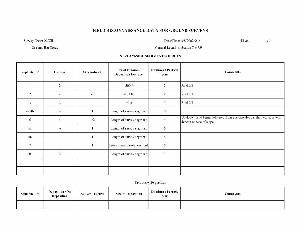
Survey Crew: Date/Time: 8/8/2002 9:15
Stream: General Location:
Smpl Site ID# Upslope Streambank Size of Erosion / Deposition Feature
Dominant Particle Size
1 2 -- ~ 500 ft. 2
2 2 -- ~100 ft. 2
3 2 -- ~50 ft. 2
4a/4b -- 1 Length of survey segment 6
5 4 1/2 Length of survey segment 6
6a -- 1 Length of survey segment 6
6b -- 1 Length of survey segment 6
7 -- 1 Intermittent throughout unit 6
8 2 -- Length of survey segment 2
Smpl Site ID# Deposition / No
Deposition Active/ Inactive Size of Deposition Dominant Particle Size
JC/CB
Big Creek Station 7.9-9.9
Rockfall
Sheet of
FIELD RECONNAISSANCE DATA FOR GROUND SURVEYS
Comments
Tributary Deposition
STREAM-SIDE SEDIMENT SOURCES
Comments
Rockfall
Rockfall
Upslope - sand being delivered from upslope along siphon corridor with deposit at base of slope
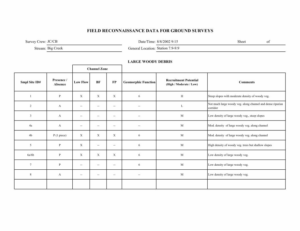
Survey Crew: Date/Time: 8/8/2002 9:15 Sheet of
Stream: General Location:
Smpl Site ID# Presence / Absence Low Flow BF FP Geomorphic Function Recruitment Potential
(High / Moderate / Low)Comments
1 P X X X 6 H Steep slopes with moderate density of woody veg.
2 A -- -- -- -- L Not much large woody veg. along channel and dense riparian corridor
3 A -- -- -- -- M Low density of large woody veg., steep slopes
4a A -- -- -- -- M Mod. density of large woody veg. along channel
4b P (1 piece) X X X 6 M Mod. density of large woody veg. along channel
5 P X -- -- 6 M High density of woody veg. trees but shallow slopes
6a/6b P X X X 6 M Low density of large woody veg.
7 P -- -- -- 6 M Low density of large woody veg.
8 A -- -- -- -- M Low density of large woody veg.
FIELD RECONNAISSANCE DATA FOR GROUND SURVEYS
LARGE WOODY DEBRIS
Channel Zone
JC/CB
Big Creek Station 7.9-9.9
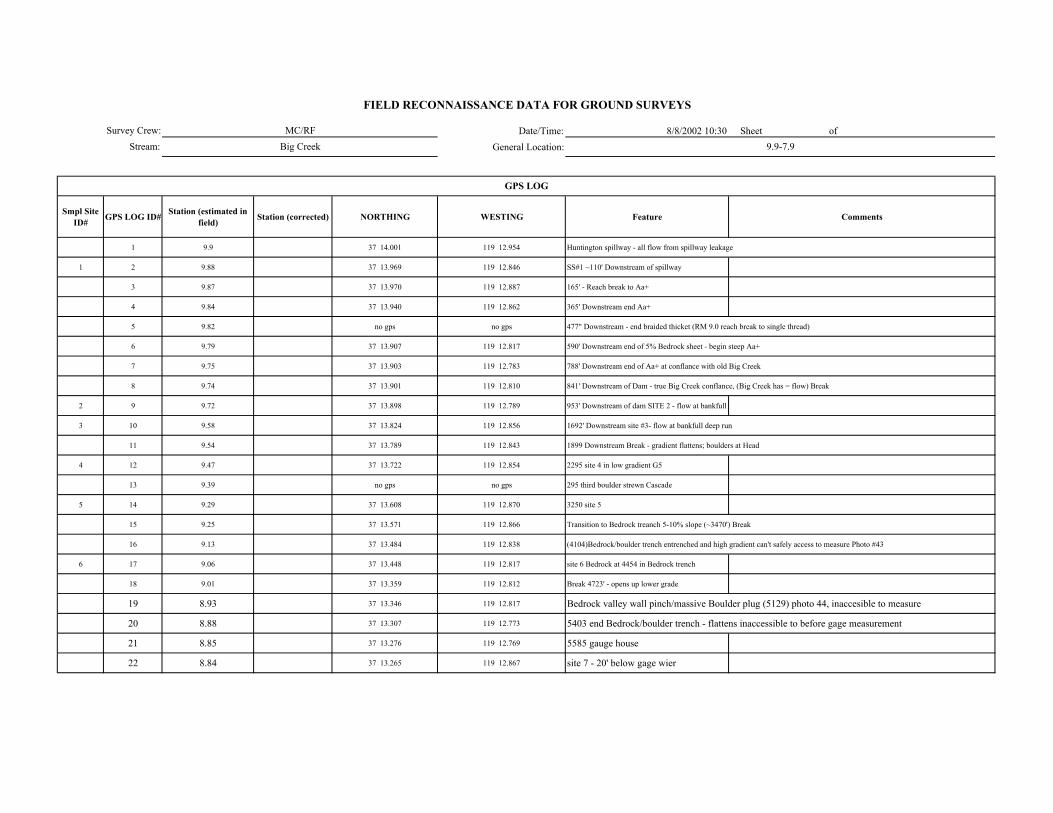
Date/Time: 8/8/2002 10:30 Sheet of General Location:
Smpl Site ID# GPS LOG ID# Station (estimated in
field) Station (corrected) NORTHING WESTING Feature Comments
1 9.9 37 14.001 119 12.954 Huntington spillway - all flow from spillway leakage
1 2 9.88 37 13.969 119 12.846 SS#1 ~110' Downstream of spillway
3 9.87 37 13.970 119 12.887 165' - Reach break to Aa+
4 9.84 37 13.940 119 12.862 365' Downstream end Aa+
5 9.82 no gps no gps 477" Downstream - end braided thicket (RM 9.0 reach break to single thread)
6 9.79 37 13.907 119 12.817 590' Downstream end of 5% Bedrock sheet - begin steep Aa+
7 9.75 37 13.903 119 12.783 788' Downstream end of Aa+ at conflance with old Big Creek
8 9.74 37 13.901 119 12.810 841' Downstream of Dam - true Big Creek conflance, (Big Creek has = flow) Break
2 9 9.72 37 13.898 119 12.789 953' Downstream of dam SITE 2 - flow at bankfull
3 10 9.58 37 13.824 119 12.856 1692' Downstream site #3- flow at bankfull deep run
11 9.54 37 13.789 119 12.843 1899 Downstream Break - gradient flattens; boulders at Head
4 12 9.47 37 13.722 119 12.854 2295 site 4 in low gradient G5
13 9.39 no gps no gps 295 third boulder strewn Cascade
5 14 9.29 37 13.608 119 12.870 3250 site 5
15 9.25 37 13.571 119 12.866 Transition to Bedrock treanch 5-10% slope (~3470') Break
16 9.13 37 13.484 119 12.838 (4104)Bedrock/boulder trench entrenched and high gradient can't safely access to measure Photo #43
6 17 9.06 37 13.448 119 12.817 site 6 Bedrock at 4454 in Bedrock trench
18 9.01 37 13.359 119 12.812 Break 4723' - opens up lower grade
19 8.93 37 13.346 119 12.817 Bedrock valley wall pinch/massive Boulder plug (5129) photo 44, inaccesible to measure
20 8.88 37 13.307 119 12.773 5403 end Bedrock/boulder trench - flattens inaccessible to before gage measurement
21 8.85 37 13.276 119 12.769 5585 gauge house
22 8.84 37 13.265 119 12.867 site 7 - 20' below gage wier
GPS LOG
Survey Crew:Stream:
FIELD RECONNAISSANCE DATA FOR GROUND SURVEYS
MC/RFBig Creek 9.9-7.9
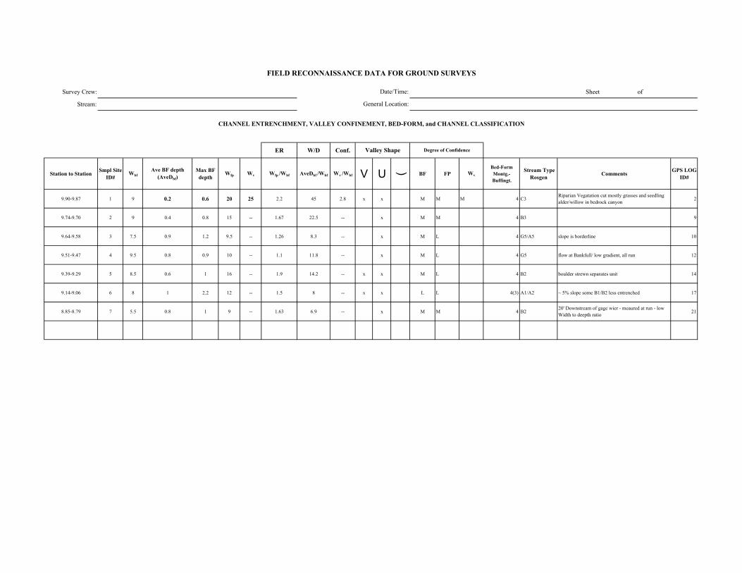
Survey Crew: Sheet of
Stream:
ER W/D Conf.
Station to Station Smpl Site ID#
WbfAve BF depth
(AveDbf)Max BF
depthWfp Wv Wfp /Wbf AveDbf /Wbf Wv /Wbf V U ( BF FP Wv
Bed-Form Montg.-Buffingt.
Stream Type Rosgen Comments GPS LOG
ID#
9.90-9.87 1 9 0.2 0.6 20 25 2.2 45 2.8 x x M M M 4 C3Riparian Vegatation cut mostly grasses and seedling alder/willow in bedrock canyon 2
9.74-9.70 2 9 0.4 0.8 15 -- 1.67 22.5 -- x M M 4 B3 9
9.64-9.58 3 7.5 0.9 1.2 9.5 -- 1.26 8.3 -- x M L 4 G5/A5 slope is borderline 10
9.51-9.47 4 9.5 0.8 0.9 10 -- 1.1 11.8 -- x M L 4 G5 flow at Bankfull/ low gradient, all run 12
9.39-9.29 5 8.5 0.6 1 16 -- 1.9 14.2 -- x x M L 4 B2 boulder strewn separates unit 14
9.14-9.06 6 8 1 2.2 12 -- 1.5 8 -- x x L L 4(3) A1/A2 ~ 5% slope some B1/B2 less entrenched 17
8.85-8.79 7 5.5 0.8 1 9 -- 1.63 6.9 -- x M M 4 B220' Downstream of gage wier - meaured at run - low Width to deepth ratio 21
FIELD RECONNAISSANCE DATA FOR GROUND SURVEYS
Degree of Confidence
CHANNEL ENTRENCHMENT, VALLEY CONFINEMENT, BED-FORM, and CHANNEL CLASSIFICATION
Valley Shape
Date/Time:
General Location:
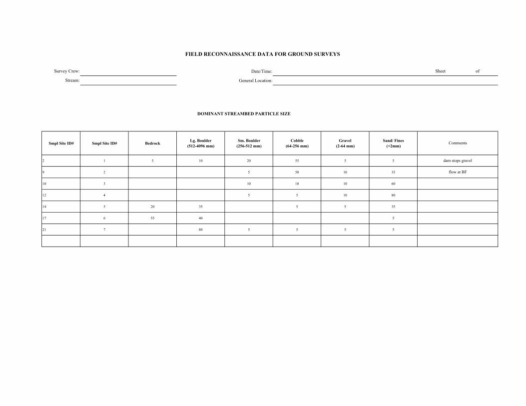
Date/Time:
General Location:
DOMINANT STREAMBED PARTICLE SIZE
Smpl Site ID# Smpl Site ID# Bedrock Lg. Boulder (512-4096 mm)
Sm. Boulder (256-512 mm)
Cobble (64-256 mm)
Gravel (2-64 mm)
Sand/ Fines (<2mm)
2 1 5 10 20 55 5 5
9 2 5 50 10 35
10 3 10 10 10 60
12 4 5 5 10 80
14 5 20 35 5 5 35
17 6 55 40 5
21 7 80 5 5 5 5
Survey Crew:
Stream:
flow at BF
FIELD RECONNAISSANCE DATA FOR GROUND SURVEYS
Sheet of
Comments
dam stops gravel
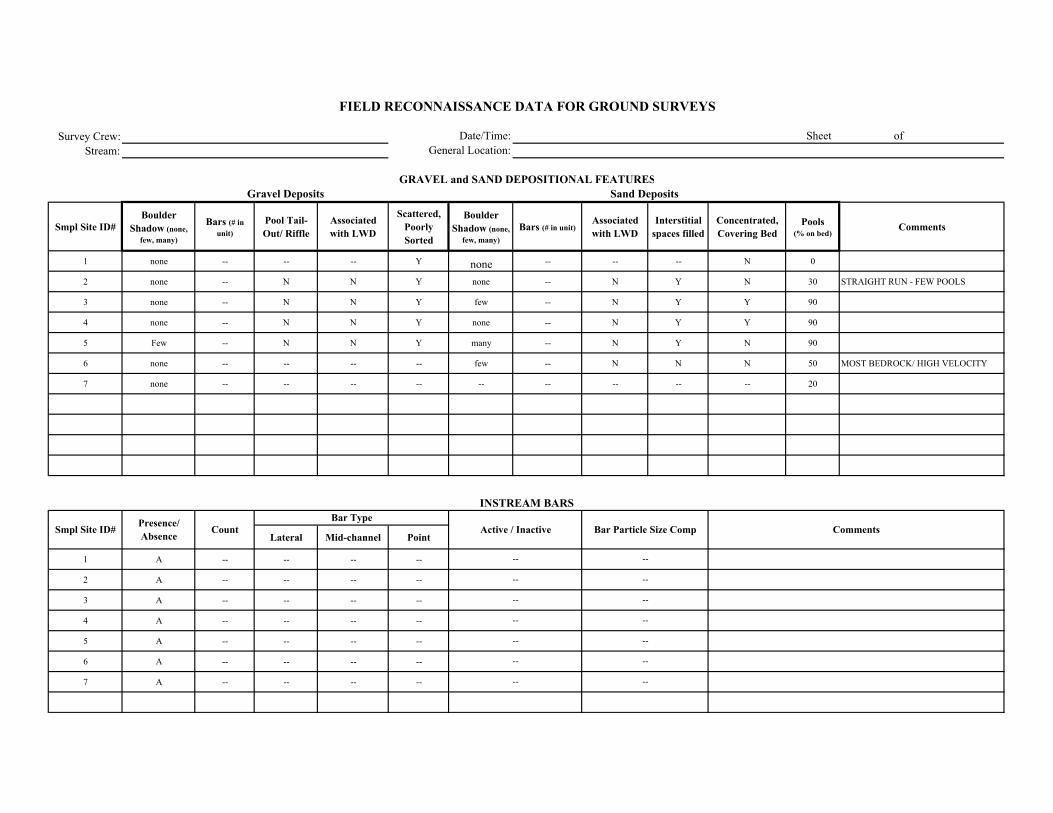
Survey Crew:Stream:
Smpl Site ID# Boulder
Shadow (none, few, many)
Bars (# in unit)
Pool Tail-Out/ Riffle
Associated with LWD
Scattered, Poorly Sorted
Boulder Shadow (none,
few, many)Bars (# in unit)
Associated with LWD
Interstitial spaces filled
Concentrated, Covering Bed
Pools (% on bed)
Comments
1 none -- -- -- Y none -- -- -- N 0
2 none -- N N Y none -- N Y N 30 STRAIGHT RUN - FEW POOLS
3 none -- N N Y few -- N Y Y 90
4 none -- N N Y none -- N Y Y 90
5 Few -- N N Y many -- N Y N 90
6 none -- -- -- -- few -- N N N 50 MOST BEDROCK/ HIGH VELOCITY
7 none -- -- -- -- -- -- -- -- -- 20
Lateral Mid-channel Point
1 A -- -- -- --
2 A -- -- -- --
3 A -- -- -- --
4 A -- -- -- --
5 A -- -- -- --
6 A -- -- -- --
7 A -- -- -- --
--
--
--
--
--
--
--
--
--
--
--
--
--
--
FIELD RECONNAISSANCE DATA FOR GROUND SURVEYS
Date/Time:General Location:
Sheet of
GRAVEL and SAND DEPOSITIONAL FEATURESGravel Deposits
Smpl Site ID# Comments
Sand Deposits
INSTREAM BARS
Presence/ Absence Count Active / Inactive Bar Particle Size Comp
Bar Type
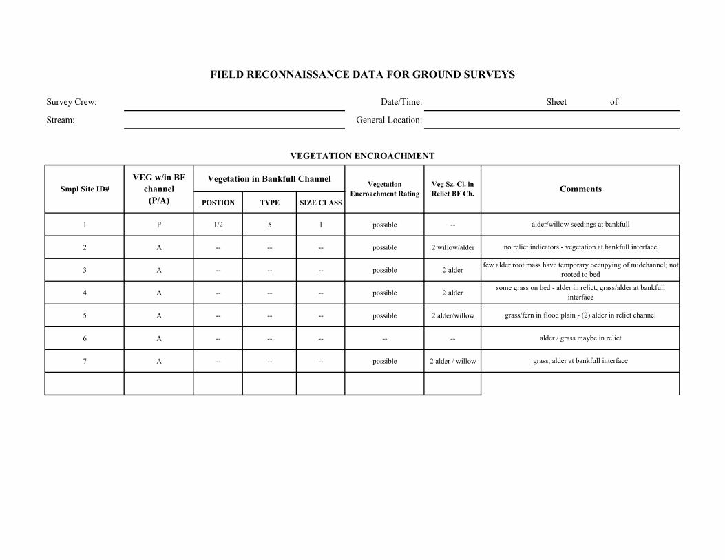
Survey Crew: Date/Time: Sheet of
Stream: General Location:
Vegetation in Bankfull Channel
POSTION TYPE SIZE CLASS
1 P 1/2 5 1 possible --
2 A -- -- -- possible 2 willow/alder
3 A -- -- -- possible 2 alder
4 A -- -- -- possible 2 alder
5 A -- -- -- possible 2 alder/willow
6 A -- -- -- -- --
7 A -- -- -- possible 2 alder / willow
Comments
VEGETATION ENCROACHMENT
FIELD RECONNAISSANCE DATA FOR GROUND SURVEYS
Smpl Site ID# VEG w/in BF
channel (P/A)
Vegetation Encroachment Rating
Veg Sz. Cl. in Relict BF Ch.
alder / grass maybe in relict
grass, alder at bankfull interface
alder/willow seedings at bankfull
no relict indicators - vegetation at bankfull interface
few alder root mass have temporary occupying of midchannel; not rooted to bed
grass/fern in flood plain - (2) alder in relict channel
some grass on bed - alder in relict; grass/alder at bankfull interface
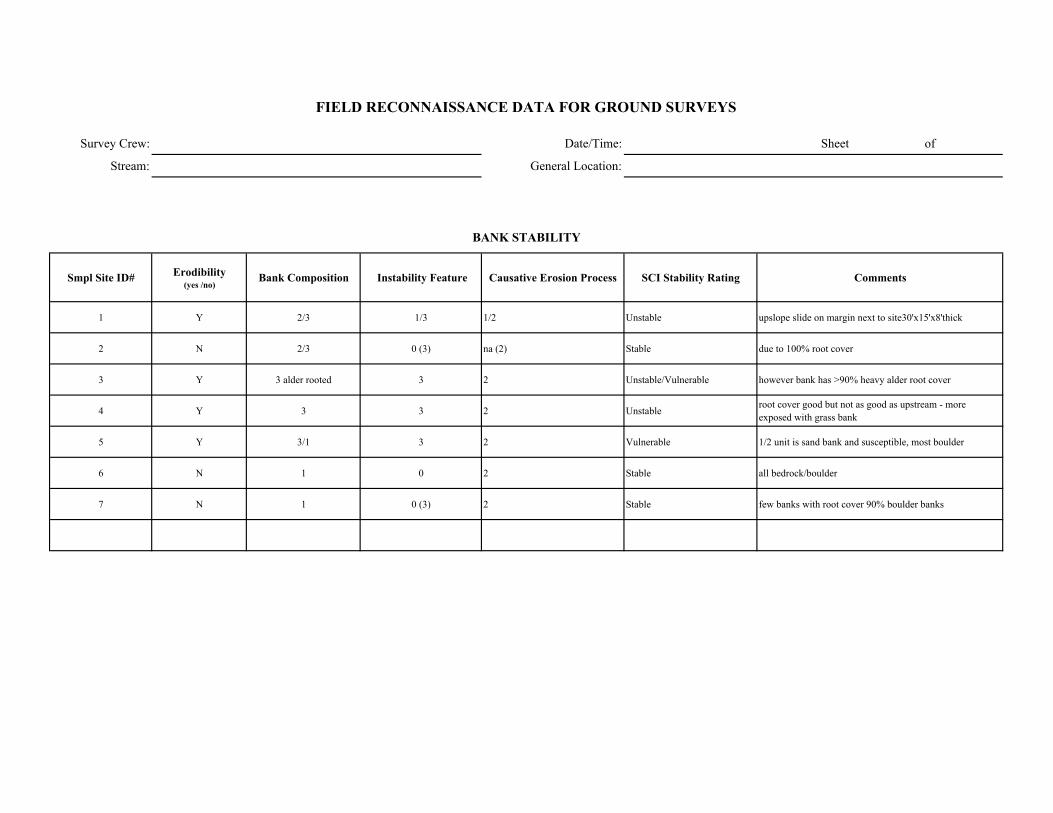
Survey Crew: Date/Time: Sheet of
Stream: General Location:
Smpl Site ID# Erodibility (yes /no)
Bank Composition Instability Feature Causative Erosion Process SCI Stability Rating Comments
1 Y 2/3 1/3 1/2 Unstable upslope slide on margin next to site30'x15'x8'thick
2 N 2/3 0 (3) na (2) Stable due to 100% root cover
3 Y 3 alder rooted 3 2 Unstable/Vulnerable however bank has >90% heavy alder root cover
4 Y 3 3 2 Unstable root cover good but not as good as upstream - more exposed with grass bank
5 Y 3/1 3 2 Vulnerable 1/2 unit is sand bank and susceptible, most boulder
6 N 1 0 2 Stable all bedrock/boulder
7 N 1 0 (3) 2 Stable few banks with root cover 90% boulder banks
FIELD RECONNAISSANCE DATA FOR GROUND SURVEYS
BANK STABILITY
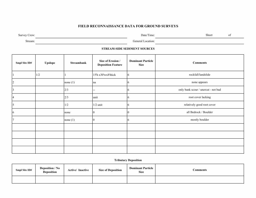
Survey Crew: Date/Time:
Stream: General Location:
Smpl Site ID# Upslope Streambank Size of Erosion / Deposition Feature
Dominant Particle Size
1 1/2 1 15'h x30'wx8'thick 6
2 none (1) na 6
3 2/3 -- 6
4 2/3 unit 6
5 1/2 1/2 unit 6
6 none 0 0
7 none (1) 0 6
Smpl Site ID# Deposition / No
Deposition Active/ Inactive Size of Deposition Dominant Particle Size
relatively good root cover
all Bedrock / Boulder
mostly boulder
Sheet of
FIELD RECONNAISSANCE DATA FOR GROUND SURVEYS
Comments
Tributary Deposition
STREAM-SIDE SEDIMENT SOURCES
Comments
rockfall/landslide
none appears
only bank scour / unercut - not bad
root cover lacking
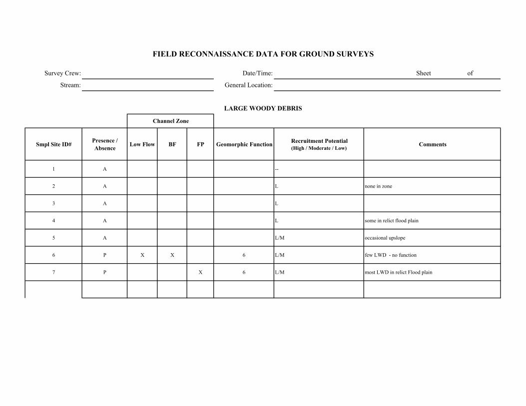
Survey Crew: Date/Time: Sheet of
Stream: General Location:
Smpl Site ID# Presence / Absence Low Flow BF FP Geomorphic Function Recruitment Potential
(High / Moderate / Low)Comments
1 A --
2 A L none in zone
3 A L
4 A L some in relict flood plain
5 A L/M occasional upslope
6 P X X 6 L/M few LWD - no function
7 P X 6 L/M most LWD in relict Flood plain
FIELD RECONNAISSANCE DATA FOR GROUND SURVEYS
LARGE WOODY DEBRIS
Channel Zone
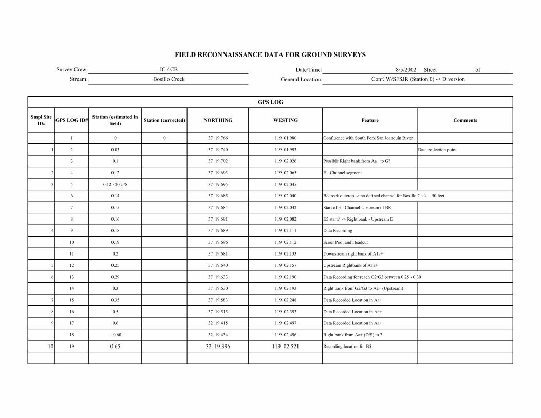
Date/Time: 8/5/2002 Sheet of
General Location:
Smpl Site ID# GPS LOG ID# Station (estimated in
field) Station (corrected) NORTHING WESTING Feature Comments
1 0 0 37 19.766 119 01.980 Confluence with South Fork San Joanquin River
1 2 0.03 37 19.740 119 01.993 Data collection point
3 0.1 37 19.702 119 02.026 Possible Right bank from Aa+ to G?
2 4 0.12 37 19.693 119 02.065 E - Channel segment
3 5 0.12 ~20'U/S 37 19.695 119 02.045
6 0.14 37 19.685 119 02.040 Bedrock outcrop -> no defined channel for Bosillo Ceek ~ 50 feet
7 0.15 37 19.684 119 02.042 Start of E - Channel Upstream of BR
8 0.16 37 19.691 119 02.082 E5 start? -> Right bank - Upstream E
4 9 0.18 37 19.689 119 02.111 Data Recording
10 0.19 37 19.696 119 02.112 Scour Pool and Headcut
11 0.2 37 19.681 119 02.133 Downstream right bank of A1a+
5 12 0.25 37 19.640 119 02.157 Upstream Rightbank of A1a+
6 13 0.29 37 19.633 119 02.190 Data Recording for reach G2/G3 between 0.25 - 0.30
14 0.3 37 19.630 119 02.193 Right bank from G2/G3 to Aa+ (Upstream)
7 15 0.35 37 19.583 119 02.248 Data Recorded Location in Aa+
8 16 0.5 37 19.515 119 02.393 Data Recorded Location in Aa+
9 17 0.6 32 19.415 119 02.497 Data Recorded Location in Aa+
18 ~ 0.60 32 19.434 119 02.496 Right bank from Aa+ (D/S) to ?
10 19 0.65 32 19.396 119 02.521 Recording location for B5
GPS LOG
Survey Crew:
Stream:
FIELD RECONNAISSANCE DATA FOR GROUND SURVEYS
JC / CB
Bosillo Creek Conf. W/SFSJR (Station 0) -> Diversion
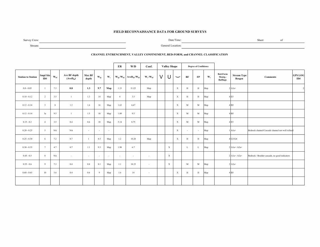
Survey Crew: Sheet of
Stream:
ER W/D Conf.
Station to Station Smpl Site ID#
WbfAve BF depth
(AveDbf)Max BF
depthWfp Wv Wfp /Wbf AveDbf /Wbf Wv /Wbf V U ( BF FP Wv
Bed-Form Montg.-Buffingt.
Stream Type Rosgen Comments GPS LOG
ID#
0.0 - 0.05 1 7.3 0.8 1.3 9.7 Map 1.33 9.125 Map X H H Map 2 A1a+ 2
0.10 - 0.12 2 3.5 1 1.3 14 Map 4 3.5 Map X H H Map 4 E5
0.12 - 0.14 3 8 1.2 1.6 16 Map 1.63 6.67 X M M Map 4 B5
0.12 - 0.14 3a 9.5 1 1.5 18 Map 1.89 9.5 X M M Map 4 B5
0.15 - 0.2 4 3.5 0.4 0.6 18 Map 5.14 8.75 X M M Map 4 E5
0.20 - 0.25 5 NA NA - - - X - - Map 1 A1a+ Bedrock channel/Cascade channel not well refined
0.25 - 0.30 6 7.2 0.7 1 8.5 Map 1.2 10.28 Map X H H Map 4 G3/G4
0.30 - 0.35 7 4.7 0.7 1.1 9.3 Map 1.98 6.7 X L L Map 2 A1a+ /A2a+
0.45 - 0.5 8 NA - - - - - - - X 2 A1a+ /A2a+ Bedrock / Boulder cascade, no good indicators
0.55 - 0.6 9 7.3 0.4 0.8 8.1 Map 1.1 18.25 - X M M Map 2 A2a+
0.60 - 0.65 10 5.6 0.4 0.6 9 Map 1.6 14 - X H H Map 4 B5
FIELD RECONNAISSANCE DATA FOR GROUND SURVEYS
Degree of Confidence
CHANNEL ENTRENCHMENT, VALLEY CONFINEMENT, BED-FORM, and CHANNEL CLASSIFICATION
Valley Shape
Date/Time:
General Location:
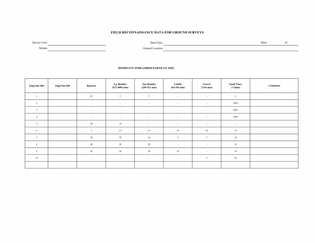
Date/Time:
General Location:
DOMINANT STREAMBED PARTICLE SIZE
Smpl Site ID# Smpl Site ID# Bedrock Lg. Boulder (512-4096 mm)
Sm. Boulder (256-512 mm)
Cobble (64-256 mm)
Gravel (2-64 mm)
Sand/ Fines (<2mm)
1 85 5 5 - - 5
2 - - - - - 100%
3 - - - - - 100%
4 - - - - - 100%
5 90 10 - - - -
6 5 2.5 2.5 25 50 10
7 40 30 10 5 5 10
8 40 30 20 - - 10
9 20 30 30 10 - 10
10 - - - - 5 95
FIELD RECONNAISSANCE DATA FOR GROUND SURVEYS
Sheet of
Comments
Survey Crew:
Stream:
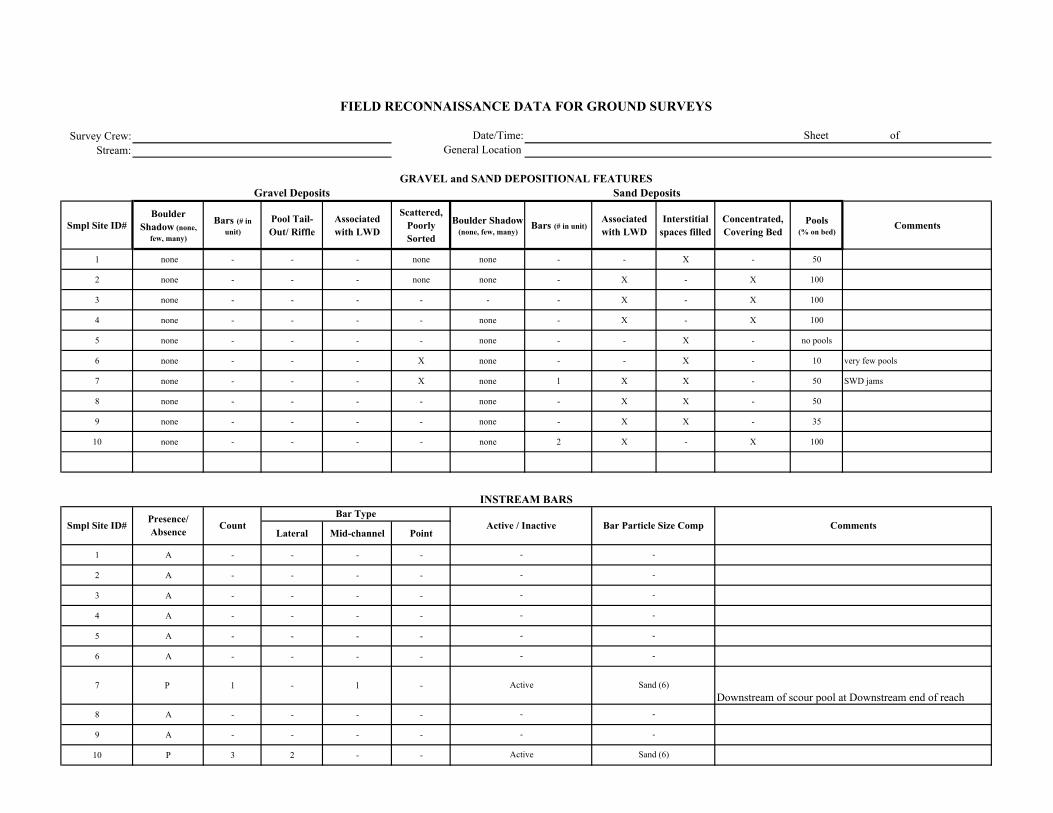
Survey Crew:Stream:
Smpl Site ID# Boulder
Shadow (none, few, many)
Bars (# in unit)
Pool Tail-Out/ Riffle
Associated with LWD
Scattered, Poorly Sorted
Boulder Shadow (none, few, many)
Bars (# in unit)Associated with LWD
Interstitial spaces filled
Concentrated, Covering Bed
Pools (% on bed)
Comments
1 none - - - none none - - X - 50
2 none - - - none none - X - X 100
3 none - - - - - - X - X 100
4 none - - - - none - X - X 100
5 none - - - - none - - X - no pools
6 none - - - X none - - X - 10 very few pools
7 none - - - X none 1 X X - 50 SWD jams
8 none - - - - none - X X - 50
9 none - - - - none - X X - 35
10 none - - - - none 2 X - X 100
Lateral Mid-channel Point
1 A - - - -
2 A - - - -
3 A - - - -
4 A - - - -
5 A - - - -
6 A - - - -
7 P 1 - 1 -
8 A - - - -
9 A - - - -
10 P 3 2 - -
Comments
Sand Deposits
INSTREAM BARS
Presence/ Absence Count Active / Inactive Bar Particle Size Comp
Bar Type
Downstream of scour pool at Downstream end of reach
FIELD RECONNAISSANCE DATA FOR GROUND SURVEYS
Date/Time:General Location:
Sheet of
GRAVEL and SAND DEPOSITIONAL FEATURESGravel Deposits
Smpl Site ID#
-
-
Sand (6)
-
Active
-
-
-
-
-
-
Sand (6)
-
-
Active
-
-
-
-
-

Survey Crew: Date/Time: Sheet of
Stream: General Location:
Vegetation in Bankfull Channel
POSTION TYPE SIZE CLASS
1 P 1 5 1 1 -
2 A - - - 1 -
3 A - - - 1 -
4 P 1 5 1 1 -
5 A - - - 1 -
6 A - - - 1 -
7 A - - - 1 -
8 A - - - 1 -
9 A - - - 1 -
10 P 1 5 1 1 - Herb and Alder on channel margin between FP & BF
Herb and Alder on channel margin between FP & BF
Herb and Alder and Cottonwood on channel margin between FP & BF
Herb and Alder on channel margin between FP & BF
Herb and Alder on channel margin between FP & BF
Comments
VEGETATION ENCROACHMENT
Note: near confluence 2 mature conifers within low flow channel
Perrinneal herb along bank upslope of bank full
FIELD RECONNAISSANCE DATA FOR GROUND SURVEYS
Smpl Site ID# VEG w/in BF
channel (P/A)
Vegetation Encroachment Rating
Veg Sz. Cl. in Relict BF Ch.
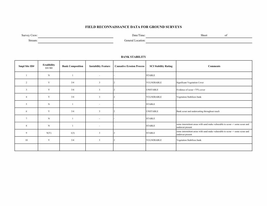
Survey Crew: Date/Time: Sheet of
Stream: General Location:
Smpl Site ID# Erodibility (yes /no)
Bank Composition Instability Feature Causative Erosion Process SCI Stability Rating Comments
1 N 1 - - STABLE
2 Y 3/4 3 2 VULNERABLE Significant Vegetation Cover
3 Y 3/4 3 2 UNSTABLE Evidence of scour <75% cover
4 Y 3/4 3 2 VULNERABLE Vegetation Stabilizes bank
5 N 1 - - STABLE
6 Y 3/4 3 2 UNSTABLE Bank scour and undercutting throughout reach
7 N 1 - - STABLE
8 N 1 - - STABLE some intermittent areas with sand make vulnerable to scour -> some scour and undercut present
9 N(Y) 1(3) 3 2 STABLE some intermittent areas with sand make vulnerable to scour -> some scour and undercut present
10 Y 3/4 3 2 VULNERABLE Vegetation Stabilizes bank
FIELD RECONNAISSANCE DATA FOR GROUND SURVEYS
BANK STABILITY
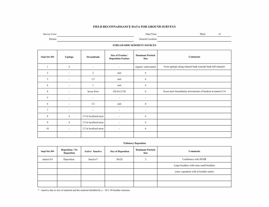
Survey Crew: Date/Time:
Stream: General Location:
Smpl Site ID# Upslope Streambank Size of Erosion / Deposition Feature
Dominant Particle Size
1 4 - - organic/ sand mantel
2 - 2 unit 6
3 - 1/2 unit 6
4 - 1 unit 6
4 - Scour Pool 8X16'x3.5'D 6
5 - - - -
6 - 1/2 unit 6
7 - - - -
8 4 1/2 in localized areas - 6
9 4 1/2 in localized areas - 6
10 - 1/2 in localized areas - 6
Smpl Site ID# Deposition / No Deposition Active/ Inactive Size of Deposition Dominant Particle
Size
station 0.0 Deposition Inactive* 30x20 2
* - inactive due to size of material and the material shielded by a ~ 20 x 30 boulder structure
Sheet of
FIELD RECONNAISSANCE DATA FOR GROUND SURVEYS
Comments
Tributary Deposition
STREAM-SIDE SEDIMENT SOURCES
Comments
From upslope along channel bank (outside bank full channel)
Scour pool immediately downstream of headcut at station 0.14
Confluence with SFSJR
Large boulders with some small boulders
some vegetation with in boulder matrix

Survey Crew: Date/Time: Sheet of
Stream: General Location:
Smpl Site ID# Presence / Absence Low Flow BF FP Geomorphic Function Recruitment Potential
(High / Moderate / Low)Comments
1 P X X X 3 Mod. Shallow slopes, banks stable - conifers with in 10 feet of channel - low density
2 P X X X 3 Mod. Shallow slope
3 P X X X 3/4/5/6 Mod. - High
4 P X X X 3/4/5/6 High
5 A - - - - Mod. Low slope but trees
6 P X X X 5 Mod. Low slope but trees
7 A - but several SWD jams
X X X 3 Mod. Low slope but trees
8 P X X X 3/6 Mod. - High Low slope but trees
9 P X X X 3 High Many trees, some areas of high bank slope
10 P X X X 3/6 Mod. Shallow slope
FIELD RECONNAISSANCE DATA FOR GROUND SURVEYS
LARGE WOODY DEBRIS
Channel Zone
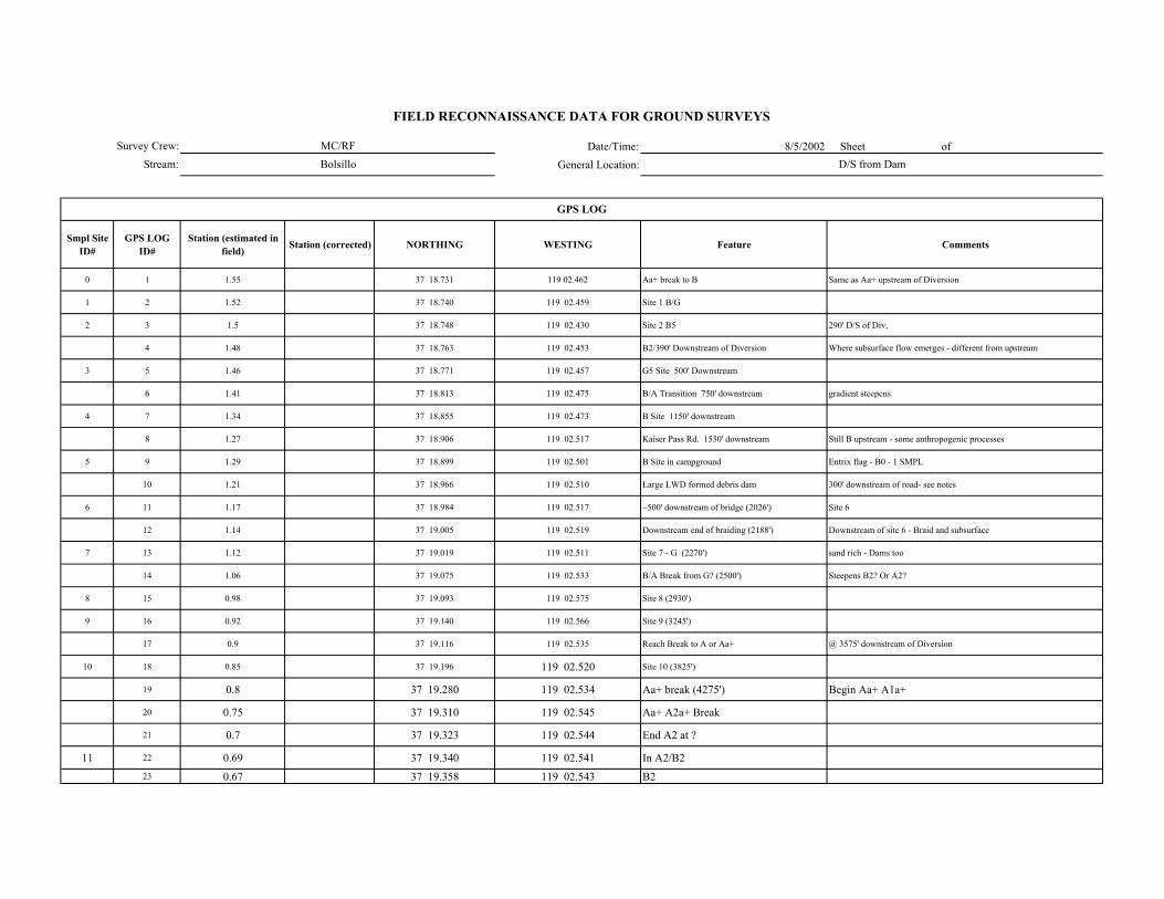
Date/Time: 8/5/2002 Sheet of General Location:
Smpl Site ID#
GPS LOG ID#
Station (estimated in field) Station (corrected) NORTHING WESTING Feature Comments
0 1 1.55 37 18.731 119 02.462 Aa+ break to B Same as Aa+ upstream of Diversion
1 2 1.52 37 18.740 119 02.459 Site 1 B/G
2 3 1.5 37 18.748 119 02.430 Site 2 B5 290' D/S of Div,
4 1.48 37 18.763 119 02.453 B2/390' Downstream of Diversion Where subsurface flow emerges - different from upstream
3 5 1.46 37 18.771 119 02.457 G5 Site 500' Downstream
6 1.41 37 18.813 119 02.475 B/A Transition 750' downstream gradient steepens
4 7 1.34 37 18.855 119 02.473 B Site 1150' downstream
8 1.27 37 18.906 119 02.517 Kaiser Pass Rd. 1530' downstream Still B upstream - some anthropogenic processes
5 9 1.29 37 18.899 119 02.501 B Site in campground Entrix flag - B0 - 1 SMPL
10 1.21 37 18.966 119 02.510 Large LWD formed debris dam 300' downstream of road- see notes
6 11 1.17 37 18.984 119 02.517 ~500' downstream of bridge (2026') Site 6
12 1.14 37 19.005 119 02.519 Downstream end of braiding (2188') Downstream of site 6 - Braid and subsurface
7 13 1.12 37 19.019 119 02.511 Site 7 - G (2270') sand rich - Dams too
14 1.06 37 19.075 119 02.533 B/A Break from G? (2500') Steepens B2? Or A2?
8 15 0.98 37 19.093 119 02.575 Site 8 (2930')
9 16 0.92 37 19.140 119 02.566 Site 9 (3245')
17 0.9 37 19.116 119 02.535 Reach Break to A or Aa+ @ 3575' downstream of Diversion
10 18 0.85 37 19.196 119 02.520 Site 10 (3825')
19 0.8 37 19.280 119 02.534 Aa+ break (4275') Begin Aa+ A1a+
20 0.75 37 19.310 119 02.545 Aa+ A2a+ Break
21 0.7 37 19.323 119 02.544 End A2 at ?
11 22 0.69 37 19.340 119 02.541 In A2/B223 0.67 37 19.358 119 02.543 B2
GPS LOG
Survey Crew:Stream:
FIELD RECONNAISSANCE DATA FOR GROUND SURVEYS
MC/RFBolsillo D/S from Dam
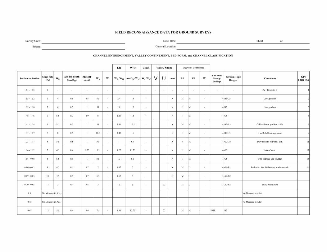
Survey Crew: Sheet of
Stream:
ER W/D Conf.
Station to Station Smpl Site ID#
WbfAve BF depth
(AveDbf)Max BF
depthWfp Wv Wfp /Wbf AveDbf /Wbf Wv /Wbf V U ( BF FP Wv
Bed-Form Montg.-Buffingt.
Stream Type Rosgen Comments GPS
LOG ID#
1.51 - 1.55 0 - - - - - - - - - - - - - - - - Aa+ Break to B 1
1.55 - 1.52 1 4 0.5 0.8 8.5 - 2.4 14 - X M M - 4 B3/G3 Low gradient 2
1.52 - 1.50 2 6 0.5 1 11 - 1.8 12 - X H M - 4 B5 Low gradient 3
1.48 - 1.46 3 5.5 0.7 0.9 8 - 1.45 7.8 - X H M - 4 G5 5
1.41 - 1.34 4 8.5 0.7 1 11 - 1.41 12.1 - X M M - 4 B2/B5 G-like -Some gradient > 4% 7
1.31 - 1.27 5 8 0.5 1 11.5 - 1.43 16 - X H M - 4 B2/B5 B in Bolsillo campground 9
1.23 - 1.17 6 5.5 0.8 1 5.5 - 1 6.9 - X H M - 4 G2/G5 Downstream of Debris jam 11
1.14 - 1.12 7 4.5 0.4 0.55 5.5 - 1.22 11.25 - X H M - 4 G5 lots of sand 12
1.06 - 0.98 8 6.5 0.8 1 8.5 - 1.3 8.1 - X H M - 4 G5 with bedrock and boulder 15
0.96 - 0.92 9 4.2 0.6 0.7 7 - 1.67 7 - X M L - 4 G1/B1 Bedrock - low W-D ratio, mud entrench 16
0.89 - 0.85 10 3.5 0.5 0.7 5.5 - 1.57 7 - X M L - 3 A2/B2
0.70 - 0.68 11 2 0.4 0.8 3 - 1.5 5 - X M L - 3 A2/B2 fairly entrenched
0.8 No Measure in A1a+ No Measure in A1a+
0.75 No Measure in A2a+ No Measure in A2a+
0.67 12 5.5 0.4 0.6 7.5 - 1.36 13.75 - X M M - HGR B2
FIELD RECONNAISSANCE DATA FOR GROUND SURVEYS
Degree of Confidence
CHANNEL ENTRENCHMENT, VALLEY CONFINEMENT, BED-FORM, and CHANNEL CLASSIFICATION
Valley Shape
Date/Time:
General Location:
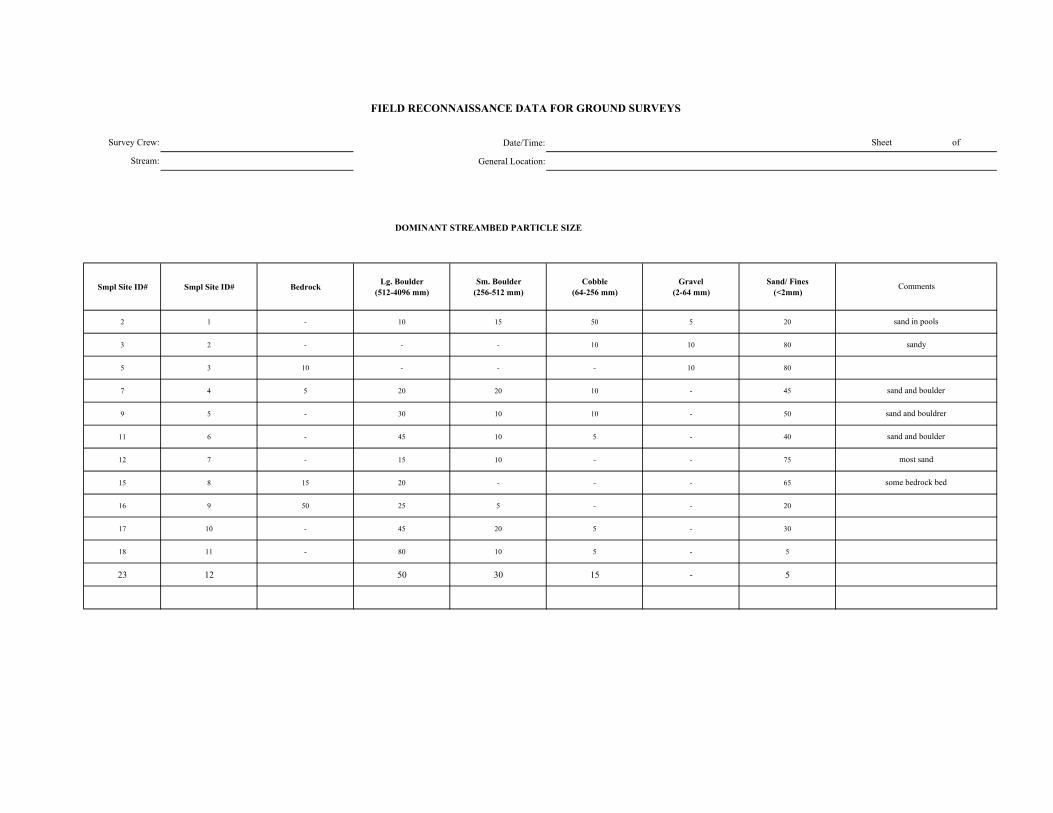
Date/Time:
General Location:
DOMINANT STREAMBED PARTICLE SIZE
Smpl Site ID# Smpl Site ID# Bedrock Lg. Boulder (512-4096 mm)
Sm. Boulder (256-512 mm)
Cobble (64-256 mm)
Gravel (2-64 mm)
Sand/ Fines (<2mm)
2 1 - 10 15 50 5 20
3 2 - - - 10 10 80
5 3 10 - - - 10 80
7 4 5 20 20 10 - 45
9 5 - 30 10 10 - 50
11 6 - 45 10 5 - 40
12 7 - 15 10 - - 75
15 8 15 20 - - - 65
16 9 50 25 5 - - 20
17 10 - 45 20 5 - 30
18 11 - 80 10 5 - 5
23 12 50 30 15 - 5
FIELD RECONNAISSANCE DATA FOR GROUND SURVEYS
Sheet of
Comments
sand in pools
sandy
sand and boulder
sand and bouldrer
sand and boulder
most sand
some bedrock bed
Survey Crew:
Stream:
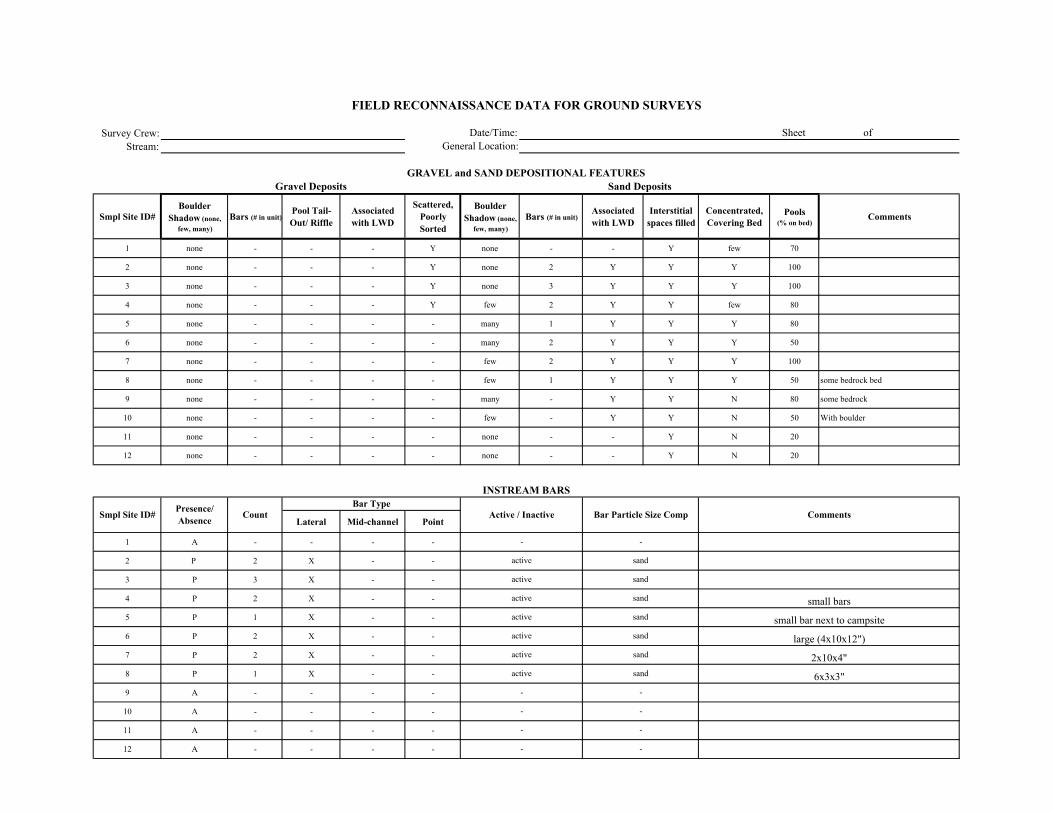
Survey Crew:Stream:
Smpl Site ID# Boulder
Shadow (none, few, many)
Bars (# in unit)Pool Tail-Out/ Riffle
Associated with LWD
Scattered, Poorly Sorted
Boulder Shadow (none,
few, many)Bars (# in unit)
Associated with LWD
Interstitial spaces filled
Concentrated, Covering Bed
Pools (% on bed)
Comments
1 none - - - Y none - - Y few 70
2 none - - - Y none 2 Y Y Y 100
3 none - - - Y none 3 Y Y Y 100
4 none - - - Y few 2 Y Y few 80
5 none - - - - many 1 Y Y Y 80
6 none - - - - many 2 Y Y Y 50
7 none - - - - few 2 Y Y Y 100
8 none - - - - few 1 Y Y Y 50 some bedrock bed
9 none - - - - many - Y Y N 80 some bedrock
10 none - - - - few - Y Y N 50 With boulder
11 none - - - - none - - Y N 20
12 none - - - - none - - Y N 20
Lateral Mid-channel Point
1 A - - - -
2 P 2 X - -
3 P 3 X - -
4 P 2 X - -
5 P 1 X - -
6 P 2 X - -
7 P 2 X - -
8 P 1 X - -
9 A - - - -
10 A - - - -
11 A - - - -
12 A - - - -
-
-
Comments
Sand Deposits
INSTREAM BARS
Presence/ Absence Count Active / Inactive Bar Particle Size Comp
Bar Type
large (4x10x12")
2x10x4"
6x3x3"
FIELD RECONNAISSANCE DATA FOR GROUND SURVEYS
Date/Time:General Location:
Sheet of
GRAVEL and SAND DEPOSITIONAL FEATURESGravel Deposits
Smpl Site ID#
small bars
small bar next to campsite
sand
--
-
active
-
- -
-
sand
sand
sand
sand
sand
sand
active
active
active
-
active
active
active
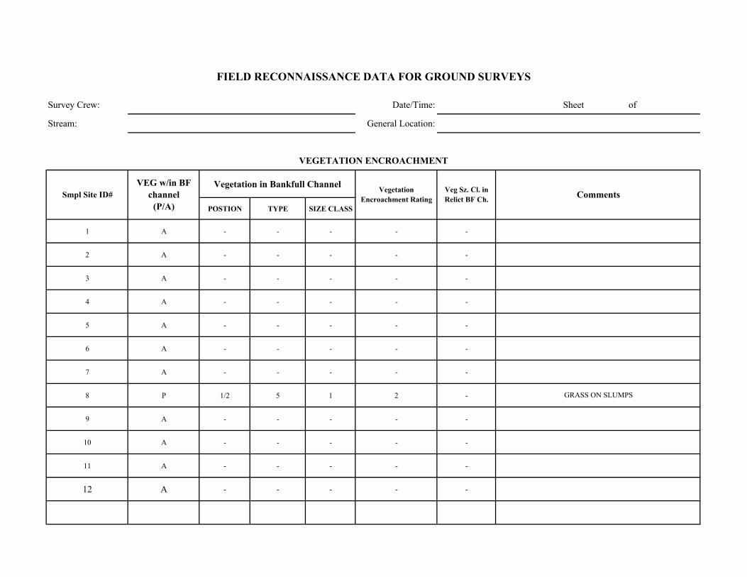
Survey Crew: Date/Time: Sheet of
Stream: General Location:
Vegetation in Bankfull Channel
POSTION TYPE SIZE CLASS
1 A - - - - -
2 A - - - - -
3 A - - - - -
4 A - - - - -
5 A - - - - -
6 A - - - - -
7 A - - - - -
8 P 1/2 5 1 2 -
9 A - - - - -
10 A - - - - -
11 A - - - - -
12 A - - - - -
GRASS ON SLUMPS
Comments
VEGETATION ENCROACHMENT
FIELD RECONNAISSANCE DATA FOR GROUND SURVEYS
Smpl Site ID# VEG w/in BF
channel (P/A)
Vegetation Encroachment Rating
Veg Sz. Cl. in Relict BF Ch.
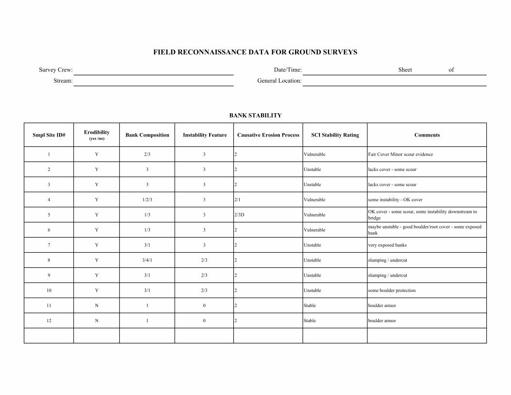
Survey Crew: Date/Time: Sheet of
Stream: General Location:
Smpl Site ID# Erodibility (yes /no)
Bank Composition Instability Feature Causative Erosion Process SCI Stability Rating Comments
1 Y 2/3 3 2 Vulnerable Fair Cover Minor scour evidence
2 Y 3 3 2 Unstable lacks cover - some scour
3 Y 3 3 2 Unstable lacks cover - some scour
4 Y 1/2/3 3 2/1 Vulnerable some instability - OK cover
5 Y 1/3 3 2/3D Vulnerable OK cover - some scour, some instability downstream to bridge
6 Y 1/3 3 2 Vulnerable maybe unstable - good boulder/root cover - some exposed bank
7 Y 3/1 3 2 Unstable very exposed banks
8 Y 3/4/1 2/3 2 Unstable slumping / undercut
9 Y 3/1 2/3 2 Unstable slumping / undercut
10 Y 3/1 2/3 2 Unstable some boulder protection
11 N 1 0 2 Stable boulder armor
12 N 1 0 2 Stable boulder armor
FIELD RECONNAISSANCE DATA FOR GROUND SURVEYS
BANK STABILITY

Survey Crew: Date/Time:
Stream: General Location:
Smpl Site ID# Upslope Streambank Size of Erosion / Deposition Feature
Dominant Particle Size
1 - 1/2 1/2 unit 6
2 - 1/2 unit 6
3 - 1/2 unit 6
4 4 1/2 1/2 unit 6
5 4 1/2 100' 6
6 - 1/2 1/2 unit 6
7 - 1/2 1/2 unit 6
8 - 1/2/3 unit 6
9 - 1/2/3 unit 6
10 - 1/2/3 unit 6
11 4/2 1 unit 3
12 4 1 unit 6
Smpl Site ID# Deposition / No Deposition Active/ Inactive Size of Deposition Dominant Particle
Size
Sheet of
FIELD RECONNAISSANCE DATA FOR GROUND SURVEYS
Comments
Tributary Deposition
STREAM-SIDE SEDIMENT SOURCES
Comments
scour at sand banks
scour and bars
scour and 3 bars
scour and deposition
scour/campsite
bank scour and sand bar (LWD jams)
bank scour and sand bar (LWD jams)
scour and slumping
scour and slumping
next to bedrock face
-
scour and slumping
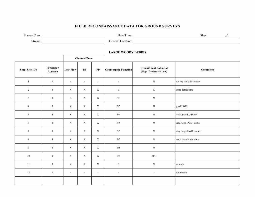
Survey Crew: Date/Time: Sheet of
Stream: General Location:
Smpl Site ID# Presence / Absence Low Flow BF FP Geomorphic Function Recruitment Potential
(High / Moderate / Low)Comments
1 A - - - - M not any wood in channel
2 P X X X 3 L some debris jams
3 P X X X 3/5 M
4 P X X X 3/5 H good LWD
5 P X X X 3/5 M lacks good LWD reer
6 P X X X 3/5 M very large LWD - dams
7 P X X X 3/5 M very Large LWD - dams
8 P X X X 3/5 M much wood / low slope
9 P X X X 3/5 M
10 P X X X 3/5 M/H
11 P X X X 6 M sporadic
12 A - - - - - not present
FIELD RECONNAISSANCE DATA FOR GROUND SURVEYS
LARGE WOODY DEBRIS
Channel Zone
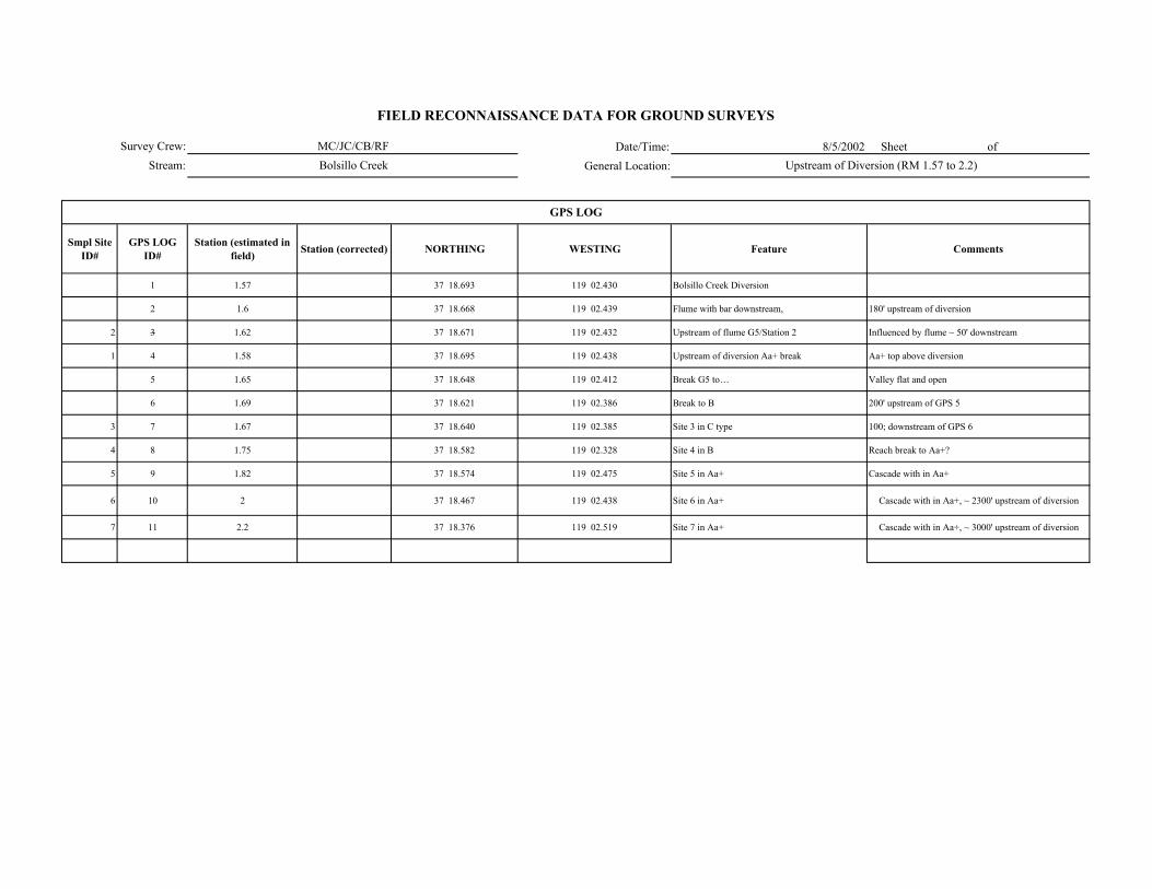
Date/Time: 8/5/2002 Sheet of General Location:
Smpl Site ID#
GPS LOG ID#
Station (estimated in field) Station (corrected) NORTHING WESTING Feature Comments
1 1.57 37 18.693 119 02.430 Bolsillo Creek Diversion
2 1.6 37 18.668 119 02.439 Flume with bar downstream, 180' upstream of diversion
2 3 1.62 37 18.671 119 02.432 Upstream of flume G5/Station 2 Influenced by flume ~ 50' downstream
1 4 1.58 37 18.695 119 02.438 Upstream of diversion Aa+ break Aa+ top above diversion
5 1.65 37 18.648 119 02.412 Break G5 to… Valley flat and open
6 1.69 37 18.621 119 02.386 Break to B 200' upstream of GPS 5
3 7 1.67 37 18.640 119 02.385 Site 3 in C type 100; downstream of GPS 6
4 8 1.75 37 18.582 119 02.328 Site 4 in B Reach break to Aa+?
5 9 1.82 37 18.574 119 02.475 Site 5 in Aa+ Cascade with in Aa+
6 10 2 37 18.467 119 02.438 Site 6 in Aa+ Cascade with in Aa+, ~ 2300' upstream of diversion
7 11 2.2 37 18.376 119 02.519 Site 7 in Aa+ Cascade with in Aa+, ~ 3000' upstream of diversion
GPS LOG
Survey Crew:Stream:
FIELD RECONNAISSANCE DATA FOR GROUND SURVEYS
MC/JC/CB/RFBolsillo Creek Upstream of Diversion (RM 1.57 to 2.2)

Survey Crew: ####### Sheet of
Stream:
ER W/D Conf.
Station to Station Smpl Site ID#
WbfAve BF depth
(AveDbf)Max BF
depthWfp Wv Wfp /Wbf AveDbf /Wbf Wv /Wbf V U ( BF FP Wv
Bed-Form Montg.-Buffingt.
Stream Type Rosgen Comments GPS LOG
ID#
1.58 - 1.62 2 7.3 0.67 0.7 9 -- 1.23 10.9 -- X H M -- 4 G5/G2 Influenced by parshall flume/gauge which is ~50' D/S of sample site 2
1.57 - 1.58 1 7.8 1 1.3 9 -- 1.15 7.8 -- X L L -- 2 A2a+ Short cascade upstream of diversion 4
1.65 - 1.69 3 9 0.8 0.9 35 -- 3.9 11.25 -- X H M -- 4 C4/C5 Broad low gradient with gravel bars 7
1.69 - 1.75 4 17 0.7 1.1 21 -- 1.23 24.3 -- X H M -- 4 B2/B3 Debris jams control small cascades/ sand in pools 8
1.75 - 1.82 5 8 1.25 2.5 10.6 -- 1.3 6.4 -- X M M -- 3 A2a+ Cascade within A2a+ 9
1.94 - 2.0 6 8 1 1.8 12 -- 1.5 8 -- X M M -- 2 A2a+ Cascade within A2a+ 10
2.15 - 2.20 7 9 1.3 2 14 -- 1.56 6.9 -- X M M -- 2 A2a+ Cascade within A2a+ 11
FIELD RECONNAISSANCE DATA FOR GROUND SURVEYS
Degree of Confidence
CHANNEL ENTRENCHMENT, VALLEY CONFINEMENT, BED-FORM, and CHANNEL CLASSIFICATION
Valley Shape
Upstream of Diversion (RM 1.57 to 2.2)General Location:
Date/Time:MC/JC/CB/RF
Bolsillo Creek
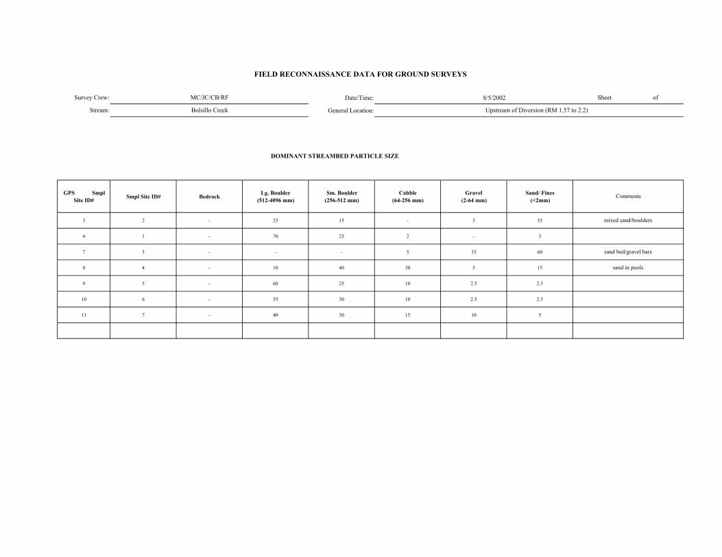
Date/Time: 8/5/2002
General Location:
DOMINANT STREAMBED PARTICLE SIZE
GPS Smpl Site ID# Smpl Site ID# Bedrock Lg. Boulder
(512-4096 mm)Sm. Boulder
(256-512 mm)Cobble
(64-256 mm)Gravel
(2-64 mm)Sand/ Fines
(<2mm)
3 2 - 25 15 - 5 55
4 1 - 70 25 2 - 3
7 3 - - - 5 35 60
8 4 - 10 40 30 5 15
9 5 - 60 25 10 2.5 2.5
10 6 - 55 30 10 2.5 2.5
11 7 - 40 30 15 10 5
MC/JC/CB/RF
Bolsillo Creek Upstream of Diversion (RM 1.57 to 2.2)
Survey Crew:
Stream:
sand bed/gravel bars
sand in pools
FIELD RECONNAISSANCE DATA FOR GROUND SURVEYS
Sheet of
Comments
mixed sand/boulders
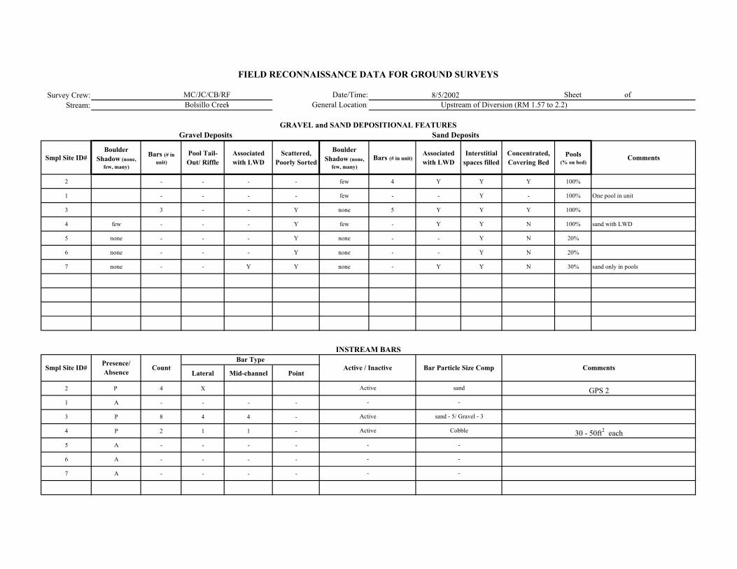
Survey Crew: 8/5/2002Stream:
Smpl Site ID# Boulder
Shadow (none, few, many)
Bars (# in unit)
Pool Tail-Out/ Riffle
Associated with LWD
Scattered, Poorly Sorted
Boulder Shadow (none,
few, many)Bars (# in unit)
Associated with LWD
Interstitial spaces filled
Concentrated, Covering Bed
Pools (% on bed)
Comments
2 - - - - few 4 Y Y Y 100%
1 - - - - few - - Y - 100% One pool in unit
3 3 - - Y none 5 Y Y Y 100%
4 few - - - Y few - Y Y N 100% sand with LWD
5 none - - - Y none - - Y N 20%
6 none - - - Y none - - Y N 20%
7 none - - Y Y none - Y Y N 30% sand only in pools
Lateral Mid-channel Point
2 P 4 X
1 A - - - -
3 P 8 4 4 -
4 P 2 1 1 -
5 A - - - -
6 A - - - -
7 A - - - -
Upstream of Diversion (RM 1.57 to 2.2)
Active
Comments
Sand Deposits
INSTREAM BARS
Presence/ Absence Count Active / Inactive
Active
Active
-
MC/JC/CB/RFBolsillo Creek
-
-
GPS 2
30 - 50ft2 each
FIELD RECONNAISSANCE DATA FOR GROUND SURVEYS
Date/Time:General Location:
Sheet of
GRAVEL and SAND DEPOSITIONAL FEATURESGravel Deposits
Smpl Site ID#
sand
-
Bar Particle Size CompBar Type
sand - 5/ Gravel - 3
Cobble
-
-
-
-
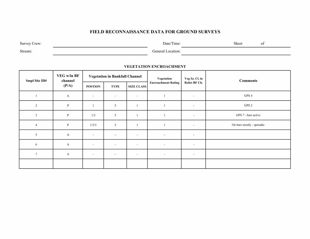
Survey Crew: Date/Time: Sheet of
Stream: General Location:
Vegetation in Bankfull Channel
POSTION TYPE SIZE CLASS
1 A - - - 1 -
2 P 1 5 1 1 -
3 P 1/3 5 1 1 -
4 P 1/2/3 5 1 1 -
5 A - - - - -
6 A - - - - -
7 A - - - - -
GPS 4
GPS 2
GPS 7 - bars active
On bars mostly - sporadic
Comments
VEGETATION ENCROACHMENT
FIELD RECONNAISSANCE DATA FOR GROUND SURVEYS
Smpl Site ID# VEG w/in BF
channel (P/A)
Vegetation Encroachment Rating
Veg Sz. Cl. in Relict BF Ch.
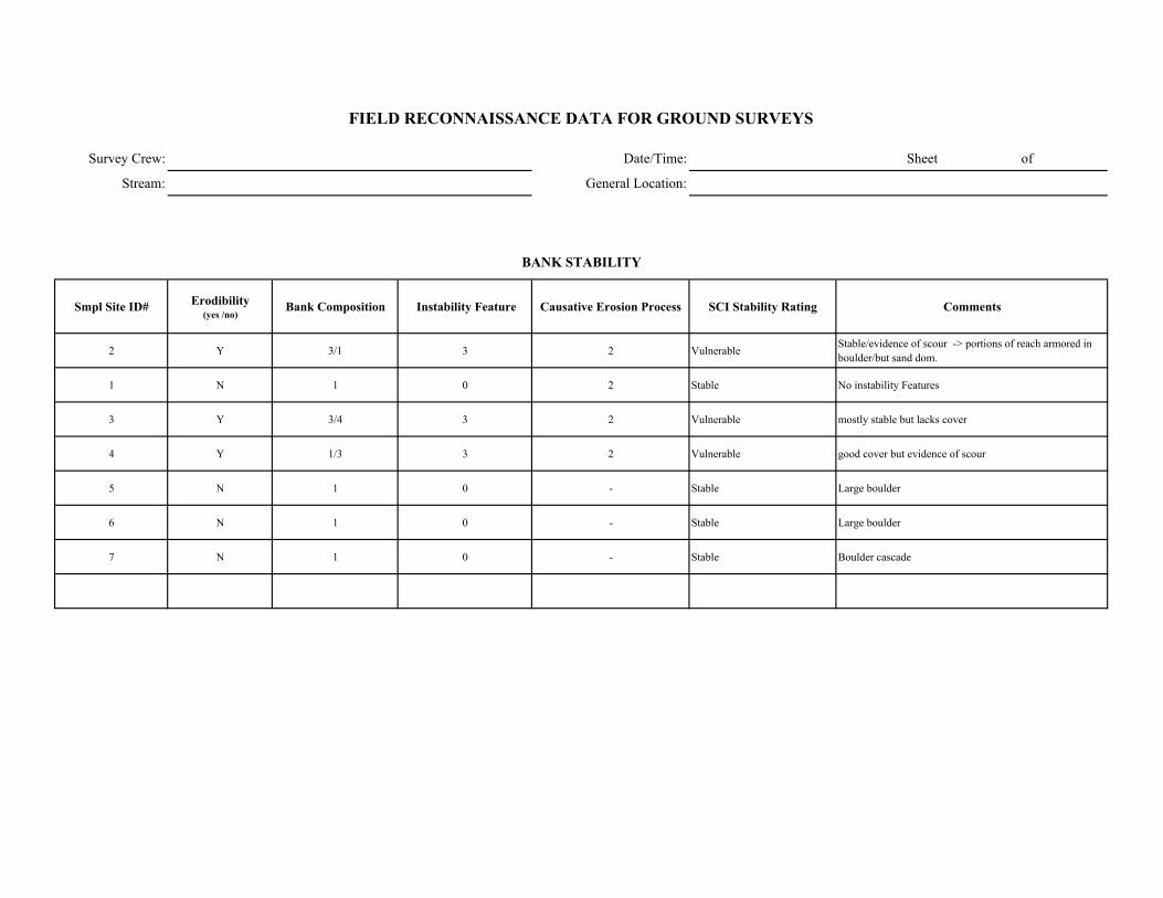
Survey Crew: Date/Time: Sheet of
Stream: General Location:
Smpl Site ID# Erodibility (yes /no)
Bank Composition Instability Feature Causative Erosion Process SCI Stability Rating Comments
2 Y 3/1 3 2 Vulnerable Stable/evidence of scour -> portions of reach armored in boulder/but sand dom.
1 N 1 0 2 Stable No instability Features
3 Y 3/4 3 2 Vulnerable mostly stable but lacks cover
4 Y 1/3 3 2 Vulnerable good cover but evidence of scour
5 N 1 0 - Stable Large boulder
6 N 1 0 - Stable Large boulder
7 N 1 0 - Stable Boulder cascade
FIELD RECONNAISSANCE DATA FOR GROUND SURVEYS
BANK STABILITY
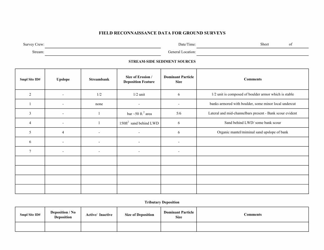
Survey Crew: Date/Time:
Stream: General Location:
Smpl Site ID# Upslope Streambank Size of Erosion / Deposition Feature
Dominant Particle Size
2 - 1/2 1/2 unit 6
1 - none - -
3 - 1 bar ~50 ft.2 area 5/6
4 - 1 150ft2 sand behind LWD 6
5 4 - - 6
6 - - - -
7 - - - -
Smpl Site ID# Deposition / No
Deposition Active/ Inactive Size of Deposition Dominant Particle Size
Organic mantel/miminal sand upslope of bank
Sheet of
FIELD RECONNAISSANCE DATA FOR GROUND SURVEYS
Comments
Tributary Deposition
STREAM-SIDE SEDIMENT SOURCES
Comments
1/2 unit is composed of boulder armor which is stable
banks armored with boulder, some minor local undercut
Lateral and mid-channelbars present - Bank scour evident
Sand behind LWD/ some bank scour
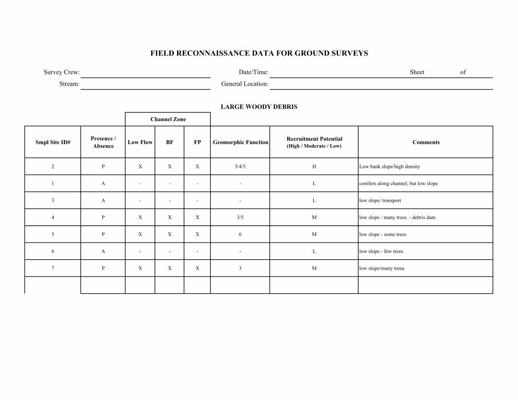
Survey Crew: Date/Time: Sheet of
Stream: General Location:
Smpl Site ID# Presence / Absence Low Flow BF FP Geomorphic Function Recruitment Potential
(High / Moderate / Low)Comments
2 P X X X 3/4/5 H Low bank slope/high density
1 A - - - - L conifers along channel, but low slope
3 A - - - - L low slope/ transport
4 P X X X 3/5 M low slope / many trees - debris dam
5 P X X X 6 M low slope - some trees
6 A - - - - L low slope - few trees
7 P X X X 3 M low slope/many treea
FIELD RECONNAISSANCE DATA FOR GROUND SURVEYS
LARGE WOODY DEBRIS
Channel Zone
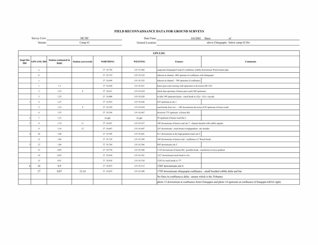
Date/Time: 8/6/2002 Sheet of General Location:
Smpl Site ID# GPS LOG ID# Station (estimated in
field) Station (corrected) NORTHING WESTING Feature Comments
a 37 18.759 119 01.468 suspected chinquapin/Camp 62 confulence imditly downstream Ward trunnel pipe
b 37 18.715 119 01.518 sidecast in channel ~400' upsteam of confluence with chinquapin
c 37 18.699 119 01.555 sidecast in channel ~ 700' upstream of confluance
1 1.2 37 18.630 119 01.621 kaiser pass road crossing walk upstreams to diversion (HC 0.0)
2 1.22 8 37 18.611 119 01.624 check dam upstream of kaiser pass road (100' upstream)
3 1.25 37 18.600 119 01.628 to falls 190' upstream kaiser - reach break to A2a+ /A1a+ cascade
1 4 1.27 37 18.593 119 01.646 255' upstream at site 1
5 1.32 9 37 18.539 119 01.654 reach break from Aa+ ~ 100' downstream diversion (670' upstream of kaiser road)
6 1.35 37 18.530 119 01.667 diversion 775' upstream of kaiser Rd
2 7 1.21 no gps no gps 30' upstream of kaiser road Site 2
3 8 1.19 11 37 18.651 119 01.637 140' downstream of kaiser road site 3 - channel shoaled with cobble angular
9 1.14 12 37 18.647 119 01.607 325' downstream - reach break to highgradient - dry boulder
4 10 1.08 37 18.705 119 01.601 611' downstream in dry high gradient reach site 4
11 1.06 37 18.718 119 01.568 760' downstream of kaiser road - confluance w/? Reach break
5 12 1.04 37 18.744 119 01.566 850' downstream site 5
13 0.99 37 18.776 119 01.546 1110' downstream of kaiser Rd - possible berak - transforms to lower gradient
14 0.95 37 18.818 119 01.541 1327' downstream reach break to Aa+
15 0.91 37 18.818 119 01.518 1520' d/s reach break to ???
6 16 0.9 37 18.833 119 01.513 1588' downstream site 6
17 0.87 13,14 37 18.835 119 01.498 1750' downstream chinquapin confluance - small boulder/cobble delta and bar
No fines in confluencce delta - unsure which is the Tributary
photo 13 downstrean at confluence from Chinqupin and photo 14 upstream at confluence (Chinqupin left/62 right)
GPS LOG
Survey Crew:Stream:
FIELD RECONNAISSANCE DATA FOR GROUND SURVEYS
MC/RFCamp 62 above Chinquapin - below camp 62 Div
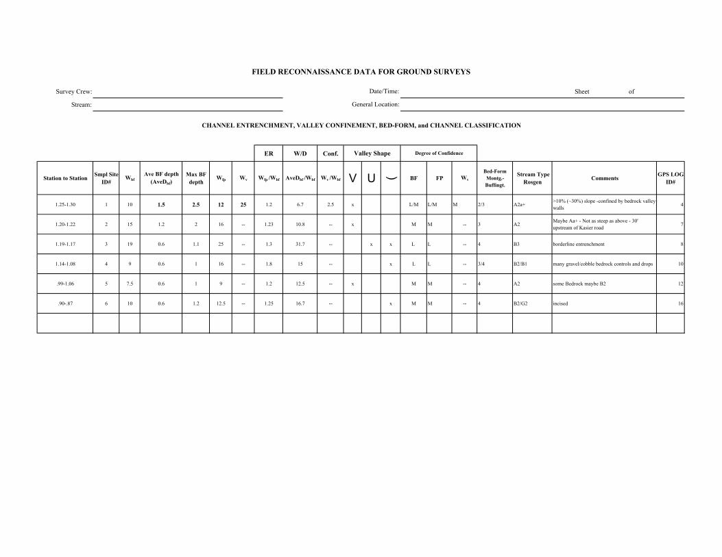
Survey Crew: Sheet of
Stream:
ER W/D Conf.
Station to Station Smpl Site ID#
WbfAve BF depth
(AveDbf)Max BF
depthWfp Wv Wfp /Wbf AveDbf /Wbf Wv /Wbf V U ( BF FP Wv
Bed-Form Montg.-Buffingt.
Stream Type Rosgen Comments GPS LOG
ID#
1.25-1.30 1 10 1.5 2.5 12 25 1.2 6.7 2.5 x L/M L/M M 2/3 A2a+>10% (~30%) slope -confined by bedrock valley walls 4
1.20-1.22 2 15 1.2 2 16 -- 1.23 10.8 -- x M M -- 3 A2Maybe Aa+ - Not as steep as above - 30' upstream of Kasier road 7
1.19-1.17 3 19 0.6 1.1 25 -- 1.3 31.7 -- x x L L -- 4 B3 borderline entrenchment 8
1.14-1.08 4 9 0.6 1 16 -- 1.8 15 -- x L L -- 3/4 B2/B1 many gravel/cobble bedrock controls and drops 10
.99-1.06 5 7.5 0.6 1 9 -- 1.2 12.5 -- x M M -- 4 A2 some Bedrock maybe B2 12
.90-.87 6 10 0.6 1.2 12.5 -- 1.25 16.7 -- x M M -- 4 B2/G2 incised 16
FIELD RECONNAISSANCE DATA FOR GROUND SURVEYS
Degree of Confidence
CHANNEL ENTRENCHMENT, VALLEY CONFINEMENT, BED-FORM, and CHANNEL CLASSIFICATION
Valley Shape
Date/Time:
General Location:
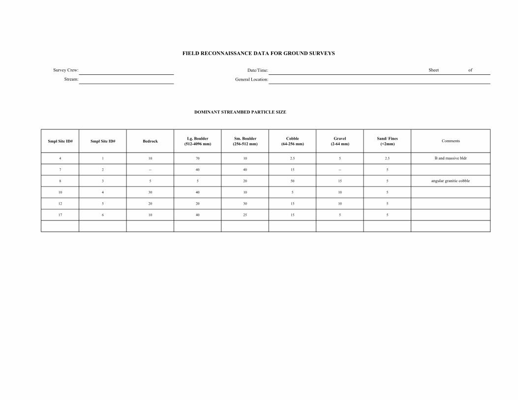
Date/Time:
General Location:
DOMINANT STREAMBED PARTICLE SIZE
Smpl Site ID# Smpl Site ID# Bedrock Lg. Boulder (512-4096 mm)
Sm. Boulder (256-512 mm)
Cobble (64-256 mm)
Gravel (2-64 mm)
Sand/ Fines (<2mm)
4 1 10 70 10 2.5 5 2.5
7 2 -- 40 40 15 -- 5
8 3 5 5 20 50 15 5
10 4 30 40 10 5 10 5
12 5 20 20 30 15 10 5
17 6 10 40 25 15 5 5
FIELD RECONNAISSANCE DATA FOR GROUND SURVEYS
Sheet of
Comments
B and massive bldr
angular granitic cobble
Survey Crew:
Stream:
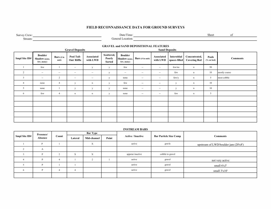
Survey Crew:Stream:
Smpl Site ID# Boulder
Shadow (none, few, many)
Bars (# in unit)
Pool Tail-Out/ Riffle
Associated with LWD
Scattered, Poorly Sorted
Boulder Shadow (none,
few, many)Bars (# in unit)
Associated with LWD
Interstitial spaces filled
Concentrated, Covering Bed
Pools (% on bed)
Comments
1 few 1 -- y y few -- -- few/no n 50
2 -- -- -- -- y -- -- -- few n 10 mostly coarse
3 -- 2 -- -- y none -- -- few/y n 5 most cobble
4 none 4 y n y few -- -- y n 10
5 none 1 y y y none -- -- y n 10
6 few 4 n n y none -- -- few n 5
Lateral Mid-channel Point
1 P 1 X
2 A
3 P 2 X X
4 P 4 1 2 1
5 P 1 1
6 P 4 4
Comments
Sand Deposits
INSTREAM BARS
Presence/ Absence Count Active / Inactive Bar Particle Size Comp
Bar Type
small 3'x10'
FIELD RECONNAISSANCE DATA FOR GROUND SURVEYS
Date/Time:General Location:
Sheet of
GRAVEL and SAND DEPOSITIONAL FEATURESGravel Deposits
Smpl Site ID#
upstream of LWD/boulder jam (20'x8')
not very active
small 6'x3'
gravle
cobble to gravel
gravel
gravel
gravel
active
active
active
apperar inactive
active
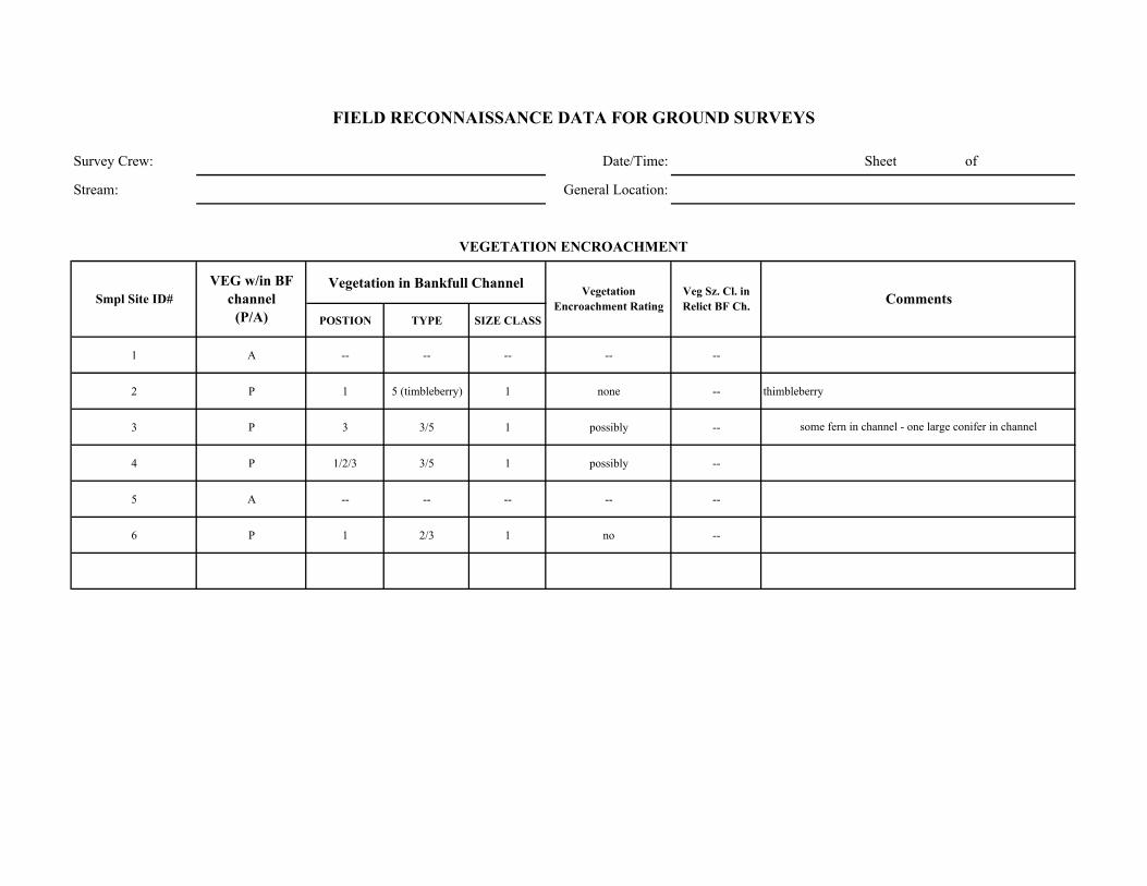
Survey Crew: Date/Time: Sheet of
Stream: General Location:
Vegetation in Bankfull Channel
POSTION TYPE SIZE CLASS
1 A -- -- -- -- --
2 P 1 5 (timbleberry) 1 none -- thimbleberry
3 P 3 3/5 1 possibly --
4 P 1/2/3 3/5 1 possibly --
5 A -- -- -- -- --
6 P 1 2/3 1 no --
some fern in channel - one large conifer in channel
Comments
VEGETATION ENCROACHMENT
FIELD RECONNAISSANCE DATA FOR GROUND SURVEYS
Smpl Site ID# VEG w/in BF
channel (P/A)
Vegetation Encroachment Rating
Veg Sz. Cl. in Relict BF Ch.
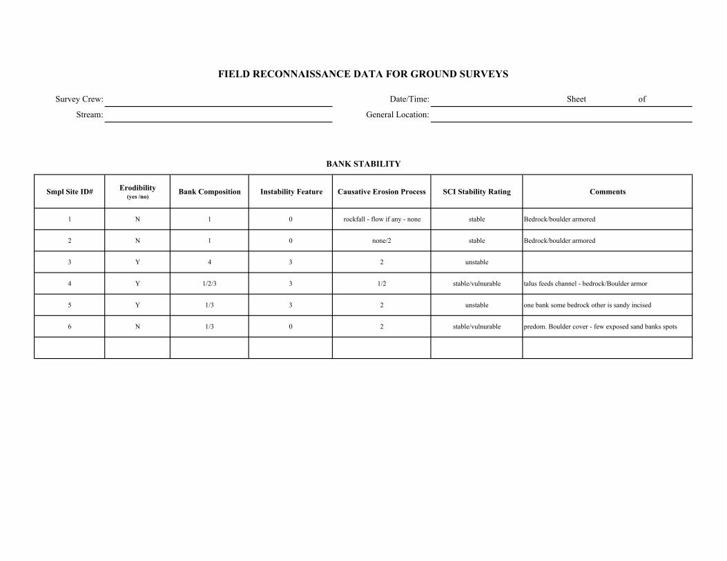
Survey Crew: Date/Time: Sheet of
Stream: General Location:
Smpl Site ID# Erodibility (yes /no)
Bank Composition Instability Feature Causative Erosion Process SCI Stability Rating Comments
1 N 1 0 rockfall - flow if any - none stable Bedrock/boulder armored
2 N 1 0 none/2 stable Bedrock/boulder armored
3 Y 4 3 2 unstable
4 Y 1/2/3 3 1/2 stable/vulnurable talus feeds channel - bedrock/Boulder armor
5 Y 1/3 3 2 unstable one bank some bedrock other is sandy incised
6 N 1/3 0 2 stable/vulnurable predom. Boulder cover - few exposed sand banks spots
FIELD RECONNAISSANCE DATA FOR GROUND SURVEYS
BANK STABILITY
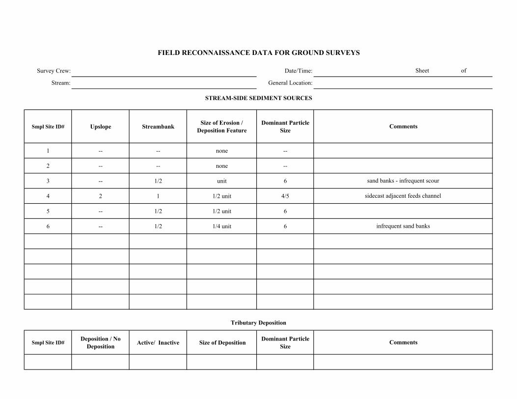
Survey Crew: Date/Time:
Stream: General Location:
Smpl Site ID# Upslope Streambank Size of Erosion / Deposition Feature
Dominant Particle Size
1 -- -- none --
2 -- -- none --
3 -- 1/2 unit 6
4 2 1 1/2 unit 4/5
5 -- 1/2 1/2 unit 6
6 -- 1/2 1/4 unit 6
Smpl Site ID# Deposition / No
Deposition Active/ Inactive Size of Deposition Dominant Particle Size
Sheet of
FIELD RECONNAISSANCE DATA FOR GROUND SURVEYS
Comments
Tributary Deposition
STREAM-SIDE SEDIMENT SOURCES
Comments
sand banks - infrequent scour
sidecast adjacent feeds channel
infrequent sand banks
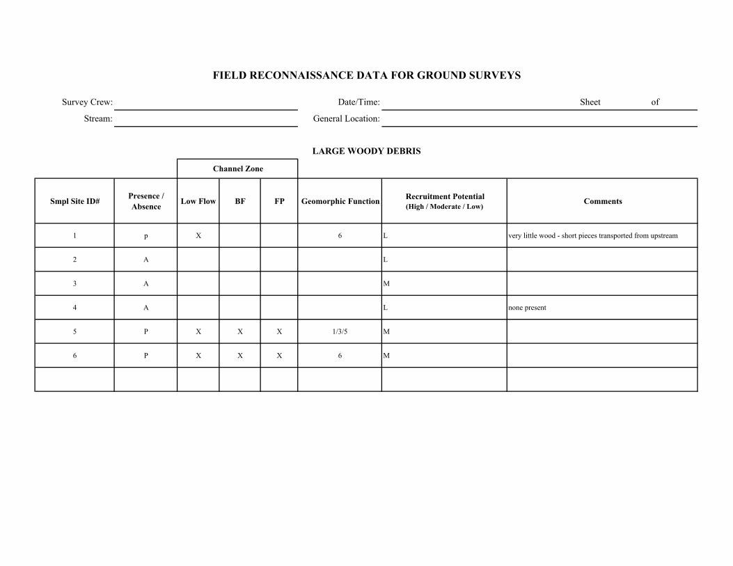
Survey Crew: Date/Time: Sheet of
Stream: General Location:
Smpl Site ID# Presence / Absence Low Flow BF FP Geomorphic Function Recruitment Potential
(High / Moderate / Low)Comments
1 p X 6 L very little wood - short pieces transported from upstream
2 A L
3 A M
4 A L none present
5 P X X X 1/3/5 M
6 P X X X 6 M
FIELD RECONNAISSANCE DATA FOR GROUND SURVEYS
LARGE WOODY DEBRIS
Channel Zone

Date/Time: 8/22/2002 14:45 Sheet of
General Location:
Smpl Site ID# GPS LOG ID# Station (estimated in
field) Station (corrected) NORTHING WESTING Feature Comments
1 1.35 37 18.514 119 01.670 Camp 62 diversion
1 2 1.39 37 18.490 119 01.686 site 1 (same as WP site ) 215' upstream
3 1.41 37 18.476 119 01.691
4 1.435 37 18.460 119 01.695 450' break to A2a+ - B2/3 from diversion to break
5 1.57 37 18.335 119 01.767 1375' top of debris jam/fan - braided (3+ braids with good bed elements)
2 6 1.59 37 18.329 119 01.775 site 2 single thread A2a+
7 1.68 37 18.132 119 01.778 1738' top of large braided section (bottom at 1.66/1662')
3 8 1.7 37 18.293 119 01.806 1857' site 3 in A2a+ that splits off and on
9 1.83 37 18.169 119 01.052 2527' End survey - still A2a+
above to RM 1.9 is boulder strewn ala crater photo 4; 40% slope cascade
313' old diversion site - conerete dam to bedrock on leftbank filled with sediment - 10' drop
GPS LOG
Survey Crew:
Stream:
FIELD RECONNAISSANCE DATA FOR GROUND SURVEYS
MC/JC/TB
Camp 62 Above Diversion 1.35-1.85
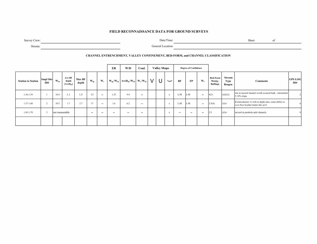
Survey Crew: Sheet of
Stream:
ER W/D Conf.
Station to Station Smpl Site ID#
Wbf
Ave BF depth
(AveDbf)
Max BF depth
Wfp Wv Wfp /Wbf AveDbf /Wbf Wv /Wbf V U ( BF FP Wv
Bed-Form Montg.-Buffingt.
Stream Type
RosgenComments GPS LOG
ID#
1.36-1.39 1 10.4 1.1 1.5 13 -- 1.25 9.4 -- x L/M L/M -- 4(3) A2(G2) site in incised channel wwith scoured bank - entrenched 5-10% slope 2
1.57-1.60 2 10.5 1.7 2.7 17 -- 1.6 6.2 -- x L/M L/M -- 2/3(4) A2a+ B entrechment /A with to depth ratio, some ability to over flow boulder banks like an E 6
1.65-1.70 3 not measurable -- -- -- -- -- x -- -- -- 2/3 A2a+ incised in parabola split channels 8
FIELD RECONNAISSANCE DATA FOR GROUND SURVEYS
Degree of Confidence
CHANNEL ENTRENCHMENT, VALLEY CONFINEMENT, BED-FORM, and CHANNEL CLASSIFICATION
Valley Shape
Date/Time:
General Location:
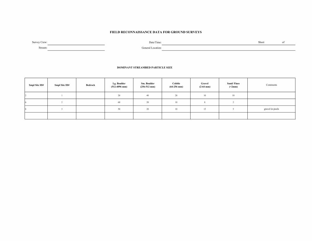
Date/Time:
General Location:
DOMINANT STREAMBED PARTICLE SIZE
Smpl Site ID# Smpl Site ID# Bedrock Lg. Boulder (512-4096 mm)
Sm. Boulder (256-512 mm)
Cobble (64-256 mm)
Gravel (2-64 mm)
Sand/ Fines (<2mm)
2 1 20 40 20 10 10
6 2 60 20 10 8 2
8 3 50 20 10 15 5
FIELD RECONNAISSANCE DATA FOR GROUND SURVEYS
Sheet of
Comments
gravel in pools
Survey Crew:
Stream:
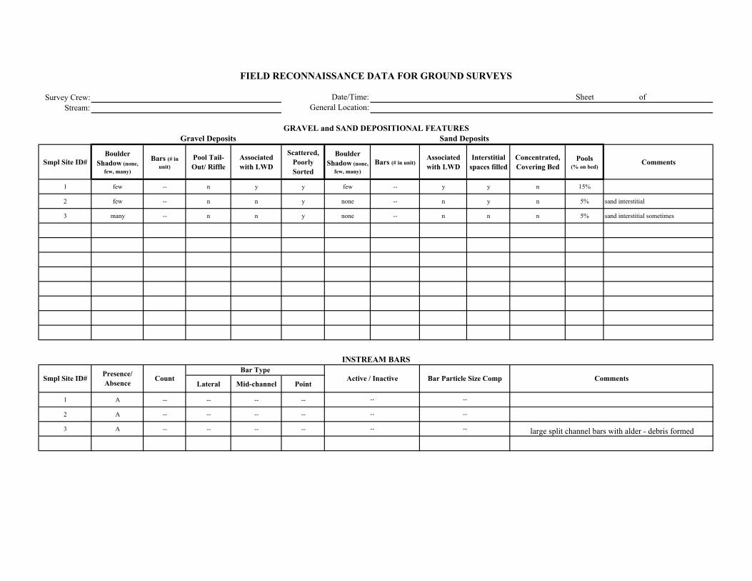
Survey Crew:Stream:
Smpl Site ID# Boulder
Shadow (none, few, many)
Bars (# in unit)
Pool Tail-Out/ Riffle
Associated with LWD
Scattered, Poorly Sorted
Boulder Shadow (none,
few, many)Bars (# in unit)
Associated with LWD
Interstitial spaces filled
Concentrated, Covering Bed
Pools (% on bed)
Comments
1 few -- n y y few -- y y n 15%
2 few -- n n y none -- n y n 5% sand interstitial
3 many -- n n y none -- n n n 5% sand interstitial sometimes
Lateral Mid-channel Point
1 A -- -- -- --
2 A -- -- -- --
3 A -- -- -- --
Comments
Sand Deposits
INSTREAM BARS
Presence/ Absence Count Active / Inactive Bar Particle Size Comp
Bar Type
FIELD RECONNAISSANCE DATA FOR GROUND SURVEYS
Date/Time:General Location:
Sheet of
GRAVEL and SAND DEPOSITIONAL FEATURESGravel Deposits
Smpl Site ID#
large split channel bars with alder - debris formed
--
--
--
--
--
--
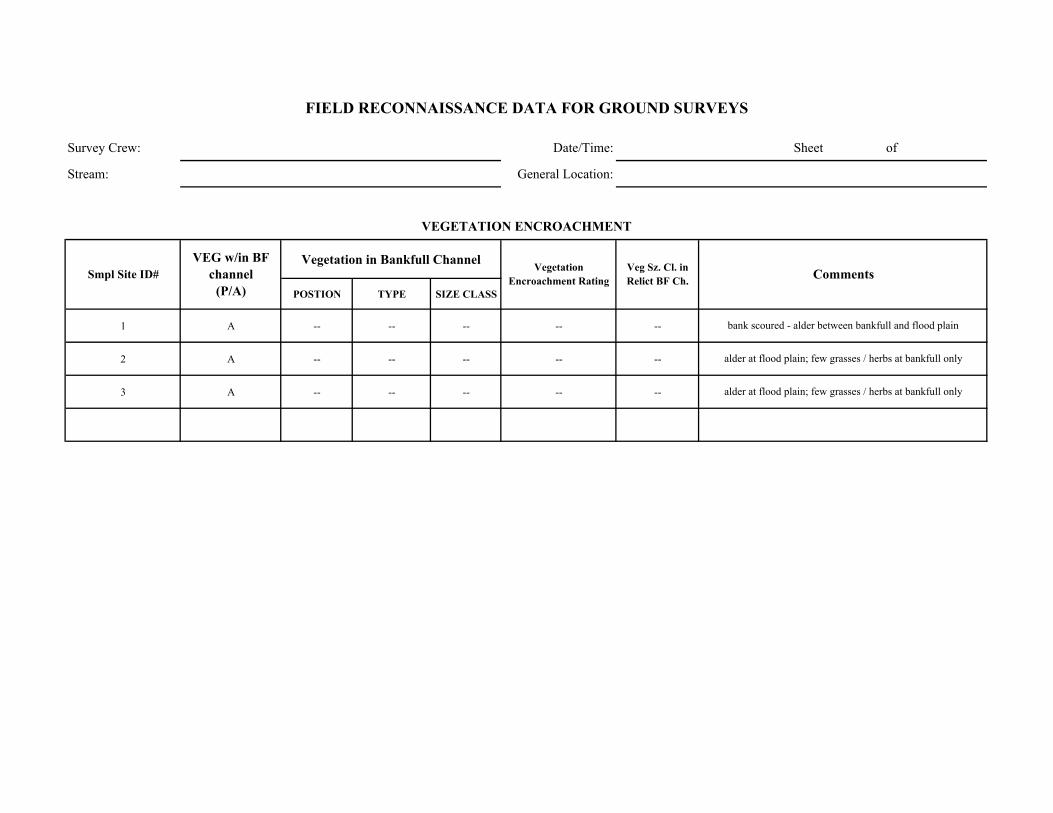
Survey Crew: Date/Time: Sheet of
Stream: General Location:
Vegetation in Bankfull Channel
POSTION TYPE SIZE CLASS
1 A -- -- -- -- --
2 A -- -- -- -- --
3 A -- -- -- -- --
bank scoured - alder between bankfull and flood plain
alder at flood plain; few grasses / herbs at bankfull only
alder at flood plain; few grasses / herbs at bankfull only
Comments
VEGETATION ENCROACHMENT
FIELD RECONNAISSANCE DATA FOR GROUND SURVEYS
Smpl Site ID# VEG w/in BF
channel (P/A)
Vegetation Encroachment Rating
Veg Sz. Cl. in Relict BF Ch.
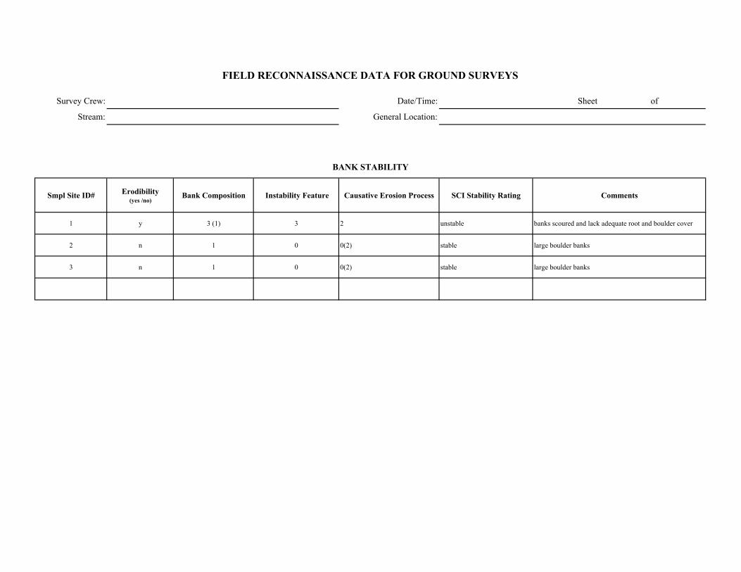
Survey Crew: Date/Time: Sheet of
Stream: General Location:
Smpl Site ID# Erodibility (yes /no)
Bank Composition Instability Feature Causative Erosion Process SCI Stability Rating Comments
1 y 3 (1) 3 2 unstable banks scoured and lack adequate root and boulder cover
2 n 1 0 0(2) stable large boulder banks
3 n 1 0 0(2) stable large boulder banks
FIELD RECONNAISSANCE DATA FOR GROUND SURVEYS
BANK STABILITY
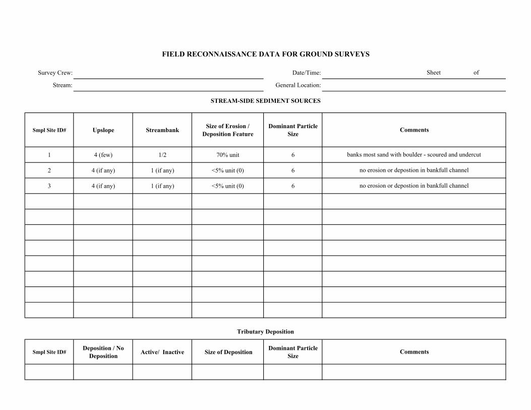
Survey Crew: Date/Time:
Stream: General Location:
Smpl Site ID# Upslope Streambank Size of Erosion / Deposition Feature
Dominant Particle Size
1 4 (few) 1/2 70% unit 6
2 4 (if any) 1 (if any) <5% unit (0) 6
3 4 (if any) 1 (if any) <5% unit (0) 6
Smpl Site ID# Deposition / No
Deposition Active/ Inactive Size of Deposition Dominant Particle Size
Sheet of
FIELD RECONNAISSANCE DATA FOR GROUND SURVEYS
Comments
Tributary Deposition
STREAM-SIDE SEDIMENT SOURCES
Comments
banks most sand with boulder - scoured and undercut
no erosion or depostion in bankfull channel
no erosion or depostion in bankfull channel
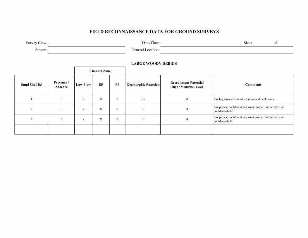
Survey Crew: Date/Time: Sheet of
Stream: General Location:
Smpl Site ID# Presence / Absence Low Flow BF FP Geomorphic Function Recruitment Potential
(High / Moderate / Low)Comments
1 P X X X 3/5 M few log jams with sand retention and bank scour
2 P X X X 3 H few pieces; boulders doing work; some LWD control on boulder/cobble
3 P X X X 3 H few pieces; boulders doing work; some LWD control on boulder/cobble
FIELD RECONNAISSANCE DATA FOR GROUND SURVEYS
LARGE WOODY DEBRIS
Channel Zone
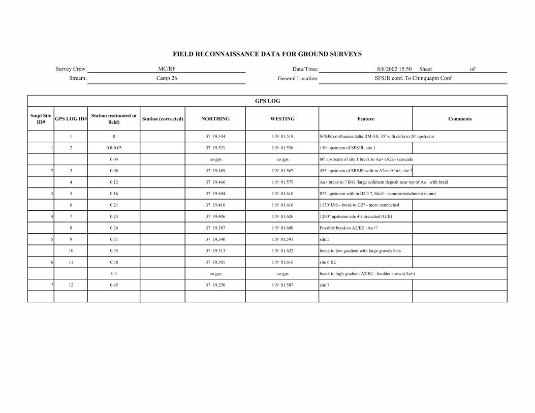
Date/Time: 8/6/2002 15:50 Sheet of
General Location:
Smpl Site ID# GPS LOG ID# Station (estimated in
field) Station (corrected) NORTHING WESTING Feature Comments
1 0 37 19.544 119 01.519 SFSJR confluence/delta RM 0.0, 35' with delta to 20' upstream
1 2 0.0-0.03 37 19.521 119 01.536 150' upstream of SFSJR, site 1
0.04 no gps no gps 60' upstream of site 1 break to Aa+ (A2a+) cascade
2 3 0.08 37 19.489 119 01.567 435' upstream of SRSJR with in A2a+/A1a+, site 2
4 0.12 37 19.466 119 01.575 Aa+ break to ? B/G /large sediment deposit near top of Aa+ with braid
3 5 0.16 37 19.444 119 01.610 875' upstream with in B2/3 ?, Site3 - some entrenchment in unit
6 0.21 37 19.416 119 01.610 1130' U/S - break to G2? - more entrenched
4 7 0.23 37 19.406 119 01.626 1200" upstream site 4 entrenched (G/B)
8 0.26 37 19.387 119 01.600 Possible break to A2/B2 ~Aa+?
5 9 0.31 37 19.340 119 01.591 site 5
10 0.35 37 19.313 119 01.622 break to low gradient with large gravels bars
6 11 0.38 37 19.301 119 01.616 site 6 B2
0.4 no gps no gps break to high gradient A2/B2 - boulder strewn(Aa+)
7 12 0.45 37 19.250 119 01.587 site 7
GPS LOG
Survey Crew:
Stream:
FIELD RECONNAISSANCE DATA FOR GROUND SURVEYS
MC/RF
Camp 26 SFSJR conf. To Chinquapin Conf
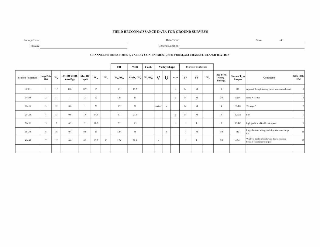
Survey Crew: Sheet of
Stream:
ER W/D Conf.
Station to Station Smpl Site ID#
WbfAve BF depth
(AveDbf)Max BF
depthWfp Wv Wfp /Wbf AveDbf /Wbf Wv /Wbf V U ( BF FP Wv
Bed-Form Montg.-Buffingt.
Stream Type Rosgen Comments GPS LOG
ID#
.0-.03 1 11.5 0.6 0.9 15 1.3 19.2 x M M 4 B2 adjacent floodplain may cause less entrenchment 2
.04-.08 2 11 1 2 17 1.54 11 x M M 2/3 A2a+ some A1a+ too 6
.12-.16 3 12 0.6 1 23 1.9 20 sort of x M M 4 B2/B3 5% slope? 5
.21-.23 4 13 0.6 1.9 14.5 1.1 21.6 x M M 4 B2/G2 F2? 7
.26-.31 5 5 0.9 2 11.5 2.3 5.5 x L L 3 A2/B2 high gradient - Boulder step pool 9
.35-.38 6 18 0.4 0.6 26 1.44 45 x H M 3/4 B2 Large boulder with gravel deposits some drops too 11
.40-.45 7 12.5 0.6 0.9 15.5 30 1.24 20.8 x L L 2/3 A2a+ Width to depth ratio skewed due to massive boulder in cascade/step pool 12
FIELD RECONNAISSANCE DATA FOR GROUND SURVEYS
Degree of Confidence
CHANNEL ENTRENCHMENT, VALLEY CONFINEMENT, BED-FORM, and CHANNEL CLASSIFICATION
Valley Shape
Date/Time:
General Location:
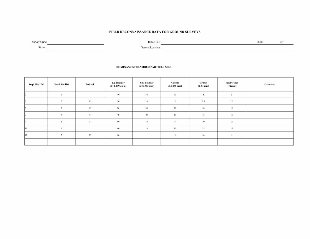
Date/Time:
General Location:
DOMINANT STREAMBED PARTICLE SIZE
Smpl Site ID# Smpl Site ID# Bedrock Lg. Boulder (512-4096 mm)
Sm. Boulder (256-512 mm)
Cobble (64-256 mm)
Gravel (2-64 mm)
Sand/ Fines (<2mm)
2 1 40 30 20 5 5
3 2 30 50 10 5 2.5 2.5
5 3 10 20 30 20 10 10
7 4 5 40 20 10 15 10
9 5 5 60 10 5 10 10
11 6 40 10 10 25 15
12 7 20 60 5 10 5
FIELD RECONNAISSANCE DATA FOR GROUND SURVEYS
Sheet of
Comments
Survey Crew:
Stream:
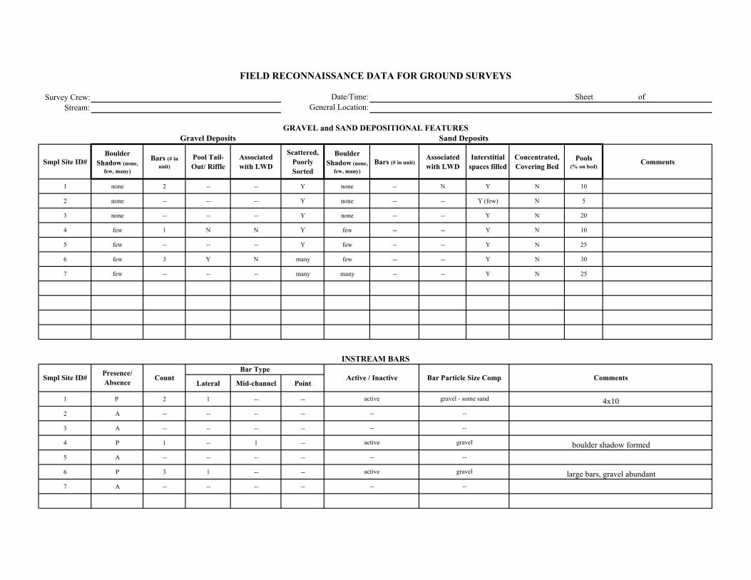
Survey Crew:Stream:
Smpl Site ID# Boulder
Shadow (none, few, many)
Bars (# in unit)
Pool Tail-Out/ Riffle
Associated with LWD
Scattered, Poorly Sorted
Boulder Shadow (none,
few, many)Bars (# in unit)
Associated with LWD
Interstitial spaces filled
Concentrated, Covering Bed
Pools (% on bed)
Comments
1 none 2 -- -- Y none -- N Y N 10
2 none -- -- -- Y none -- -- Y (few) N 5
3 none -- -- -- Y none -- -- Y N 20
4 few 1 N N Y few -- -- Y N 10
5 few -- -- -- Y few -- -- Y N 25
6 few 3 Y N many few -- -- Y N 30
7 few -- -- -- many many -- -- Y N 25
Lateral Mid-channel Point
1 P 2 1 -- --
2 A -- -- -- --
3 A -- -- -- --
4 P 1 -- 1 --
5 A -- -- -- --
6 P 3 1 -- --
7 A -- -- -- --
Comments
Sand Deposits
INSTREAM BARS
Presence/ Absence Count Active / Inactive Bar Particle Size Comp
Bar Type
large bars, gravel abundant
FIELD RECONNAISSANCE DATA FOR GROUND SURVEYS
Date/Time:General Location:
Sheet of
GRAVEL and SAND DEPOSITIONAL FEATURESGravel Deposits
Smpl Site ID#
4x10
boulder shadow formed
gravel - some sand
--
--
gravel
--
gravel
--
--
active
--
active
--
--
active
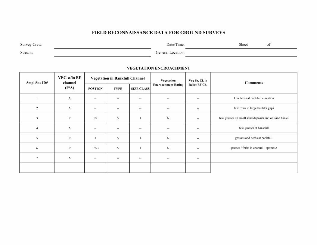
Survey Crew: Date/Time: Sheet of
Stream: General Location:
Vegetation in Bankfull Channel
POSTION TYPE SIZE CLASS
1 A -- -- -- -- --
2 A -- -- -- -- --
3 P 1/2 5 1 N --
4 A -- -- -- -- --
5 P 1 5 1 N --
6 P 1/2/3 5 1 N --
7 A -- -- -- -- --
grasses and herbs at bankfull
grasses / forbs in channel - sporadic
Few ferns at bankfull elavation
few frens in large boulder gaps
few grasses on small sand deposits and on sand banks
few grasses at bankfull
Comments
VEGETATION ENCROACHMENT
FIELD RECONNAISSANCE DATA FOR GROUND SURVEYS
Smpl Site ID# VEG w/in BF
channel (P/A)
Vegetation Encroachment Rating
Veg Sz. Cl. in Relict BF Ch.

Survey Crew: Date/Time: Sheet of
Stream: General Location:
Smpl Site ID# Erodibility (yes /no)
Bank Composition Instability Feature Causative Erosion Process SCI Stability Rating Comments
1 Y 1/3 3 2 vulnerable/Unstable some boulder armor and sand bank undercut
2 N 1 0 2 stable few sand banks (<5% of unit)
3 Y 1/3 3 2 vulnerable/Unstable trees good root cover through
4 Y 1/3 3 2 vulnerable/Unstable 1/2 unit boulder - few spots with undercut
5 Y 1/3 0 2 stable vulnerable due to sand banks - mostly boulder
6 Y 3/1 3/2 2 Unstable some good root cover
7 N 1 0 -- stable all boulder / bedrock
FIELD RECONNAISSANCE DATA FOR GROUND SURVEYS
BANK STABILITY
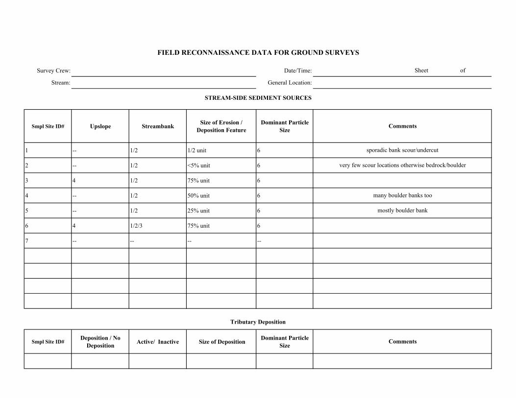
Survey Crew: Date/Time:
Stream: General Location:
Smpl Site ID# Upslope Streambank Size of Erosion / Deposition Feature
Dominant Particle Size
1 -- 1/2 1/2 unit 6
2 -- 1/2 <5% unit 6
3 4 1/2 75% unit 6
4 -- 1/2 50% unit 6
5 -- 1/2 25% unit 6
6 4 1/2/3 75% unit 6
7 -- -- -- --
Smpl Site ID# Deposition / No
Deposition Active/ Inactive Size of Deposition Dominant Particle Size
Sheet of
FIELD RECONNAISSANCE DATA FOR GROUND SURVEYS
Comments
Tributary Deposition
STREAM-SIDE SEDIMENT SOURCES
Comments
sporadic bank scour/undercut
very few scour locations otherwise bedrock/boulder
many boulder banks too
mostly boulder bank

Survey Crew: Date/Time: Sheet of
Stream: General Location:
Smpl Site ID# Presence / Absence Low Flow BF FP Geomorphic Function Recruitment Potential
(High / Moderate / Low)Comments
1 P X X 5 L/M Not a big factor
2 A L/M not present in unit
3 A L/M not really around
4 A some
5 P X X 6 L not a big factor or frequent
6 P X 6 M not much
7 P X 6 L infrequenly observed
FIELD RECONNAISSANCE DATA FOR GROUND SURVEYS
LARGE WOODY DEBRIS
Channel Zone
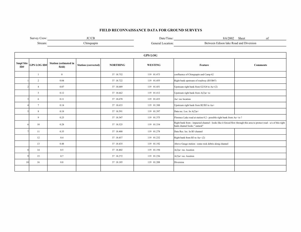
Date/Time: 8/6/2002 Sheet of General Location:
Smpl Site ID# GPS LOG ID# Station (estimated in
field) Station (corrected) NORTHING WESTING Feature Comments
1 0 37 18.752 119 01.473 confluence of Chinquapin and Camp 62
1 2 0.04 37 18.722 119 01.455 Right bank upstream of roadway (B3/B4?)
2 4 0.07 37 18.689 119 01.451 Upstream right bank from G2/G4 to Aa+(2)
5 0.12 37 18.662 119 01.412 Upstream right bank from A(2)a+ to
3 6 0.11 37 18.670 119 01.433 Aa+ rec location
4 7 0.14 37 18.633 119 01.388 Upstream right bank from B2/B3 to Aa+
5 8 0.18 37 18.591 119 01.397 Data rec. Loc. In A(2)a+
9 0.25 37 18.547 119 01.375 Florence Lake road at station 0.2 - possible right bank from Aa+ to ?
6 10 0.28 37 18.525 119 01.334
7 11 0.35 37 18.488 119 01.278 Data Rec. loc. In B3 channel
12 0.4 37 18.457 119 01.232 Right bank from B3 to Aa+ (2)
13 0.48 37 18.435 119 01.192 Above Gauge station - some rock debris along channel
8 14 0.5 37 18.402 119 01.194 A(2)a+ rec. location
9 15 0.7 37 18.272 119 01.236 A(2)a+ rec. location
10 16 0.8 37 18.185 119 01.208 Diversion
FIELD RECONNAISSANCE DATA FOR GROUND SURVEYS
JC/CBChinquapin Between Edison lake Road and Diversion
Right bank from - impacted channel - looks like it forced flow through this area to protect road - u/s of this right bank channel looks " natural"
GPS LOG
Survey Crew:Stream:
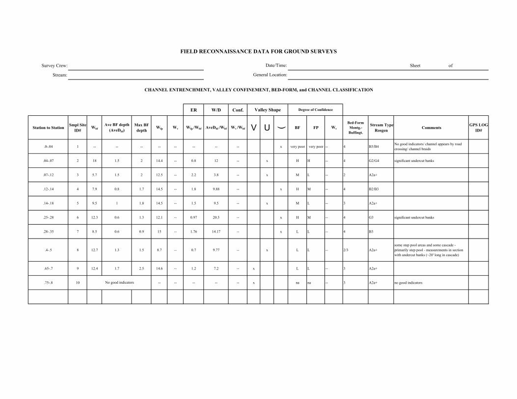
Survey Crew: Sheet of
Stream:
ER W/D Conf.
Station to Station Smpl Site ID#
WbfAve BF depth
(AveDbf)Max BF
depthWfp Wv Wfp /Wbf AveDbf /Wbf Wv /Wbf V U ( BF FP Wv
Bed-Form Montg.-Buffingt.
Stream Type Rosgen Comments GPS LOG
ID#
.0-.04 1 -- -- -- -- -- -- -- -- x very poor very poor -- 4 B3/B4No good indicators/ channel appears by road crossing/ channel braids
.04-.07 2 18 1.5 2 14.4 -- 0.8 12 -- x H H -- 4 G2/G4 significant undercut banks
.07-.12 3 5.7 1.5 2 12.5 -- 2.2 3.8 -- x M L -- 2 A2a+
.12-.14 4 7.9 0.8 1.7 14.5 -- 1.8 9.88 -- x H M -- 4 B2/B3
.14-.18 5 9.5 1 1.8 14.5 -- 1.5 9.5 -- x M L -- 3 A2a+
.25-.28 6 12.3 0.6 1.3 12.1 -- 0.97 20.5 -- x H M -- 4 G3 significant undercut banks
.28-.35 7 8.5 0.6 0.9 15 -- 1.76 14.17 -- x L L -- 4 B3
.4-.5 8 12.7 1.3 1.5 8.7 -- 0.7 9.77 -- x L L -- 2/3 A2a+some step pool areas and some cascade - primarily step pool - measurements in section with undercut banks (~20' long in cascade)
.65-.7 9 12.4 1.7 2.5 14.6 -- 1.2 7.2 -- x L L -- 3 A2a+
.75-.8 10 -- -- -- -- -- x na na -- 3 A2a+ no good indicators No good indicators
FIELD RECONNAISSANCE DATA FOR GROUND SURVEYS
Degree of Confidence
CHANNEL ENTRENCHMENT, VALLEY CONFINEMENT, BED-FORM, and CHANNEL CLASSIFICATION
Valley Shape
Date/Time:
General Location:

Date/Time:
General Location:
DOMINANT STREAMBED PARTICLE SIZE
Smpl Site ID# Smpl Site ID# Bedrock Lg. Boulder (512-4096 mm)
Sm. Boulder (256-512 mm)
Cobble (64-256 mm)
Gravel (2-64 mm)
Sand/ Fines (<2mm)
1 -- -- 15 30 40 15
2 5 20 10 15 35 15
3 10 60 20 1 2 7
4 -- 20 20 30 20 10
5 -- 35 35 10 10 10
6 -- 5 -- 60 15 20
7 -- -- 5 60 15 20
8 25 50 15 10 5 10
9 10 50 20 10 10 5
10 10 50 20 10 10 5
Survey Crew:
Stream:
FIELD RECONNAISSANCE DATA FOR GROUND SURVEYS
Sheet of
Comments
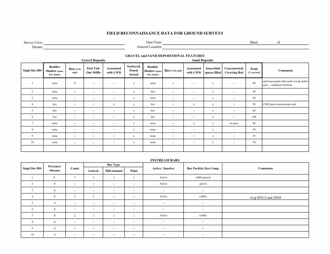
Survey Crew:Stream:
Smpl Site ID# Boulder
Shadow (none, few, many)
Bars (# in unit)
Pool Tail-Out/ Riffle
Associated with LWD
Scattered, Poorly Sorted
Boulder Shadow (none,
few, many)Bars (# in unit)
Associated with LWD
Interstitial spaces filled
Concentrated, Covering Bed
Pools (% on bed)
Comments
1 none 4 -- -- x none 1 -- x -- 90sand associated with small woody debris jams - -sediment retention
2 none 1 -- -- x few -- -- x -- 50
3 none -- -- -- x none -- -- x -- 50
4 few -- -- x x few -- x x -- 50 LWD jam at downstream end
5 few -- -- -- x few -- -- x -- 60
6 few -- -- -- x few -- -- x -- 100
7 none -- -- -- x none -- x x in areas 80
8 none -- -- -- x none -- -- x -- 30
9 none -- -- -- x none -- -- x -- 35
10 none -- -- -- x none -- -- x -- 30
Lateral Mid-channel Point
1 P 7 3 3 1
2 P 1 1 -- --
3 A -- -- -- --
4 P 2 2 -- --
5 A -- -- -- --
6 A -- -- -- --
7 P 2 1 1 --
8 A -- -- -- --
9 A -- -- -- --
10 A -- -- -- --
Active
Active
--
Active
--
--
Active
--
--
--
cobble/gravel
gravel
--
cobble
--
--
cobble
--
--
--
Avg 60X12 and 20X8
FIELD RECONNAISSANCE DATA FOR GROUND SURVEYS
Date/Time:General Location:
Sheet of
GRAVEL and SAND DEPOSITIONAL FEATURESGravel Deposits
Smpl Site ID# Comments
Sand Deposits
INSTREAM BARS
Presence/ Absence Count Active / Inactive Bar Particle Size Comp
Bar Type
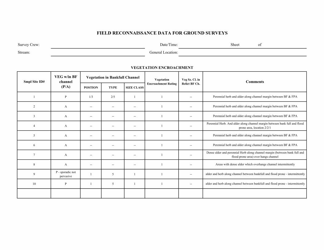
Survey Crew: Date/Time: Sheet of
Stream: General Location:
Vegetation in Bankfull Channel
POSTION TYPE SIZE CLASS
1 P 1/3 2/5 1 1 --
2 A -- -- -- 1 --
3 A -- -- -- 1 --
4 A -- -- -- 1 --
5 A -- -- -- 1 --
6 A -- -- -- 1 --
7 A -- -- -- 1 --
8 A -- -- -- 1 --
9 P - sporadic not pervasive 1 5 1 1 --
10 P 1 5 1 1 --
Perennial herb and alder along channel margin between BF & FPA
Comments
VEGETATION ENCROACHMENT
FIELD RECONNAISSANCE DATA FOR GROUND SURVEYS
Smpl Site ID# VEG w/in BF
channel (P/A)
Vegetation Encroachment Rating
Veg Sz. Cl. in Relict BF Ch.
alder and herb along channel between bankfull and flood prone - intermittently
alder and herb along channel between bankfull and flood prone - intermittently
Perennial herb and alder along channel margin between BF & FPA
Perennial herb and alder along channel margin between BF & FPA
Perennial herb and alder along channel margin between BF & FPA
Perennial herb and alder along channel margin between BF & FPA
Perennial Herb. And alder along channel margin between bank full and flood prone area, location 2/2/1
Dense alder and perennial Herb along channel margin (between bank full and flood prone area) over hangs channel
Areas with dense alder which overhangs channel intermittently
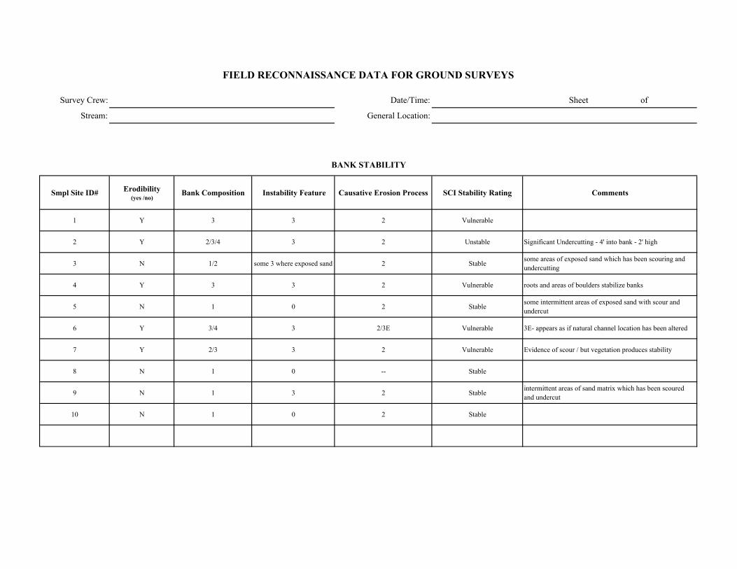
Survey Crew: Date/Time: Sheet of
Stream: General Location:
Smpl Site ID# Erodibility (yes /no)
Bank Composition Instability Feature Causative Erosion Process SCI Stability Rating Comments
1 Y 3 3 2 Vulnerable
2 Y 2/3/4 3 2 Unstable Significant Undercutting - 4' into bank - 2' high
3 N 1/2 some 3 where exposed sand 2 Stable some areas of exposed sand which has been scouring and undercutting
4 Y 3 3 2 Vulnerable roots and areas of boulders stabilize banks
5 N 1 0 2 Stable some intermittent areas of exposed sand with scour and undercut
6 Y 3/4 3 2/3E Vulnerable 3E- appears as if natural channel location has been altered
7 Y 2/3 3 2 Vulnerable Evidence of scour / but vegetation produces stability
8 N 1 0 -- Stable
9 N 1 3 2 Stable intermittent areas of sand matrix which has been scoured and undercut
10 N 1 0 2 Stable
FIELD RECONNAISSANCE DATA FOR GROUND SURVEYS
BANK STABILITY
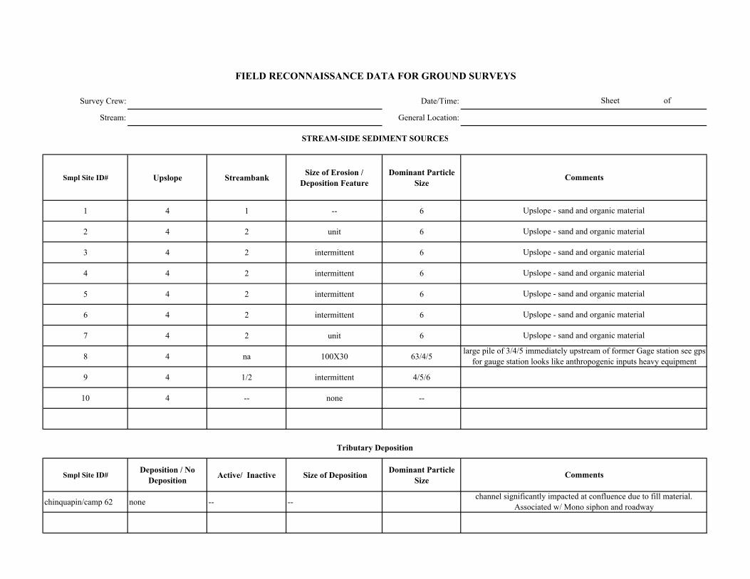
Survey Crew: Date/Time:
Stream: General Location:
Smpl Site ID# Upslope Streambank Size of Erosion / Deposition Feature
Dominant Particle Size
1 4 1 -- 6
2 4 2 unit 6
3 4 2 intermittent 6
4 4 2 intermittent 6
5 4 2 intermittent 6
6 4 2 intermittent 6
7 4 2 unit 6
8 4 na 100X30 63/4/5
9 4 1/2 intermittent 4/5/6
10 4 -- none --
Smpl Site ID# Deposition / No
Deposition Active/ Inactive Size of Deposition Dominant Particle Size
chinquapin/camp 62 none -- --channel significantly impacted at confluence due to fill material.
Associated w/ Mono siphon and roadway
Upslope - sand and organic material
Upslope - sand and organic material
Upslope - sand and organic material
large pile of 3/4/5 immediately upstream of former Gage station see gps for gauge station looks like anthropogenic inputs heavy equipment
Sheet of
FIELD RECONNAISSANCE DATA FOR GROUND SURVEYS
Comments
Tributary Deposition
STREAM-SIDE SEDIMENT SOURCES
Comments
Upslope - sand and organic material
Upslope - sand and organic material
Upslope - sand and organic material
Upslope - sand and organic material

Survey Crew: Date/Time: Sheet of
Stream: General Location:
Smpl Site ID# Presence / Absence Low Flow BF FP Geomorphic Function Recruitment Potential
(High / Moderate / Low)Comments
1 A -- -- -- -- M trees but shallow slopes
2 P 1 piece -- x x 6 H some dead trees and significant undercutting
3 P -- x x 6 H trees/ relatively step slopes and some undercut banks
4 P x x x 3/5/6 H trees and undercut banks
5 P 2-3 pieces x x x 6 M
6 P x x x 6 M
7 P x x x 3/6 H
8 A -- -- -- -- H conifers along bank some area of steep slopes
9 A -- -- -- -- H steep slopes / many trees
10 A -- -- -- -- H steep slopes / many trees
FIELD RECONNAISSANCE DATA FOR GROUND SURVEYS
LARGE WOODY DEBRIS
Channel Zone
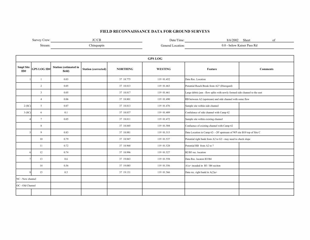
Date/Time: 8/6/2002 Sheet of
General Location:
Smpl Site ID# GPS LOG ID# Station (estimated in
field) Station (corrected) NORTHING WESTING Feature Comments
1 1 0.03 37 18.775 119 01.452 Data Rec. Location
2 0.05 37 18.813 119 01.463 Potential Reach Break from A2? (Disregard)
3 0.05 37 18.817 119 01.461 Large debris jam - flow splits with newly formed side channel to the east
4 0.06 37 18.801 119 01.490 RB between A2 (upstream) and side channel with some flow
2 (SC) 5 0.07 37 18.813 119 01.476 Sample site within side channel
3 (SC) 6 0.1 37 18.837 119 01.489 Confulence of side channel with Camp 62
4 7 0.05 37 18.811 119 01.472 Sample site within existing channel
8 37 18.845 119 01.504 Confuence of existing channel with Camp 62
5 9 0.83 37 18.881 119 01.515 Data Location in Camp 62- ~20' upstream of WP site B10 top of Site C
10 0.79 37 18.947 119 01.537 Potential right bank from A2 to G2 - may need to check slope
11 0.72 37 18.968 119 01.528 Potential RB from A2 to ?
6 12 0.74 37 18.996 119 01.527 B2/B3 rec. location
7 13 0.6 37 19.063 119 01.558 Data Rec. locaton B3/B4
14 0.56 37 19.085 119 01.556 A1a+ incuded in B3 / B4 seciton
8 15 0.5 37 19.131 119 01.566 Data rec. right bank/in A(2)a+
NC - New channel
OC - Old Channel
GPS LOG
Survey Crew:
Stream:
FIELD RECONNAISSANCE DATA FOR GROUND SURVEYS
JC/CB
Chinquapin 0.0 - below Kaiser Pass Rd
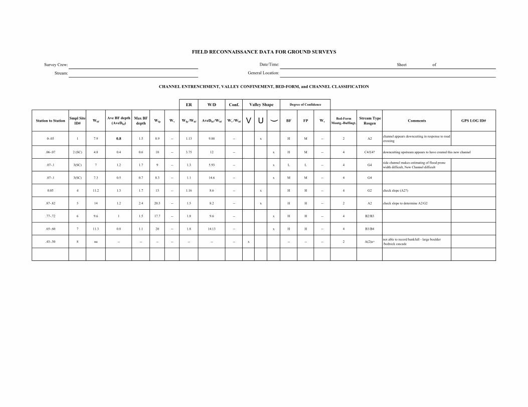
Survey Crew: Sheet of
Stream:
ER W/D Conf.
Station to Station Smpl Site ID#
WbfAve BF depth
(AveDbf)Max BF
depthWfp Wv Wfp /Wbf AveDbf /Wbf Wv /Wbf V U ( BF FP Wv
Bed-Form Montg.-Buffingt.
Stream Type Rosgen Comments GPS LOG ID#
0-.05 1 7.9 0.8 1.5 8.9 -- 1.13 9.88 -- x H M -- 2 A2 channel appears downcutting in response to road crossing
.06-.07 2 (SC) 4.8 0.4 0.6 18 -- 3.75 12 -- x H M -- 4 C4/E4? downcutting upstream appears to have created this new channel
.07-.1 3(SC) 7 1.2 1.7 9 -- 1.3 5.93 -- x L L -- 4 G4 side channel makes estimating of flood prone width difficult, New Channel difficult
.07-.1 3(SC) 7.3 0.5 0.7 8.3 -- 1.1 14.6 -- x M M -- 4 G4
0.05 4 11.2 1.3 1.7 13 -- 1.16 8.6 -- x H H -- 4 G2 check slope (A2?)
.87-.82 5 14 1.2 2.4 20.5 -- 1.5 8.2 -- x H H -- 2 A2 check slope to determine A2/G2
.77-.72 6 9.6 1 1.5 17.7 -- 1.8 9.6 -- x H H -- 4 B2/B3
.65-.60 7 11.3 0.8 1.1 20 -- 1.8 14.13 -- x H H -- 4 B3/B4
.45-.50 8 na -- -- -- -- -- -- -- x -- -- -- 2 A(2)a+ not able to record bankfull - large boulder /bedrock cascade
FIELD RECONNAISSANCE DATA FOR GROUND SURVEYS
Degree of Confidence
CHANNEL ENTRENCHMENT, VALLEY CONFINEMENT, BED-FORM, and CHANNEL CLASSIFICATION
Valley Shape
Date/Time:
General Location:

Date/Time:
General Location:
DOMINANT STREAMBED PARTICLE SIZE
Smpl Site ID# Smpl Site ID# Bedrock Lg. Boulder (512-4096 mm)
Sm. Boulder (256-512 mm)
Cobble (64-256 mm)
Gravel (2-64 mm)
Sand/ Fines (<2mm)
1 -- 15 50 20 10 5
2 (SC) -- -- -- 20 50 30
3(SC) -- -- -- 10 60 30
4 20 10 40 15 10 5
5 10 30 30 10 10 10
6 -- 5 40 30 15 10
7 -- -- 10 40 40 10
8 20 75 -- -- -- 5
Survey Crew:
Stream:
significant duff material in channel
FIELD RECONNAISSANCE DATA FOR GROUND SURVEYS
Sheet of
Comments
much of material is angular
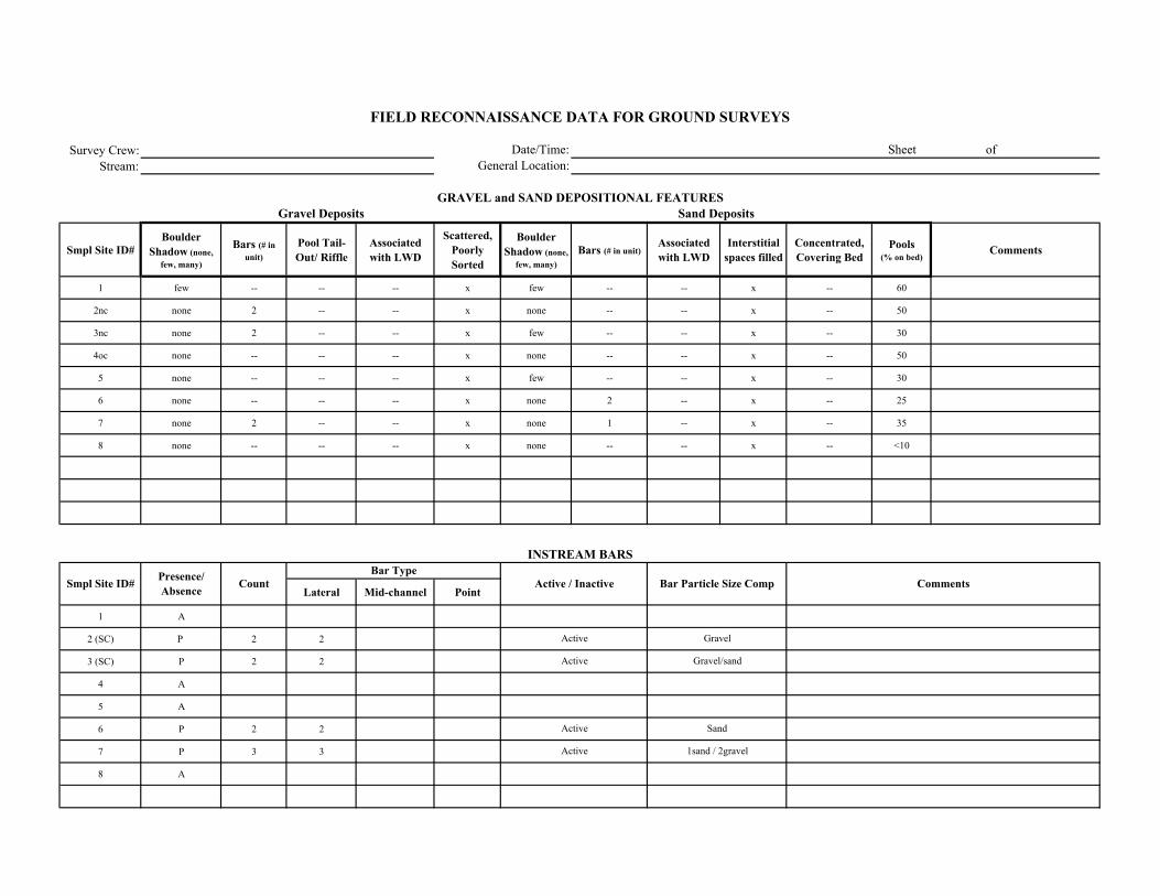
Survey Crew:Stream:
Smpl Site ID# Boulder
Shadow (none, few, many)
Bars (# in unit)
Pool Tail-Out/ Riffle
Associated with LWD
Scattered, Poorly Sorted
Boulder Shadow (none,
few, many)Bars (# in unit)
Associated with LWD
Interstitial spaces filled
Concentrated, Covering Bed
Pools (% on bed)
Comments
1 few -- -- -- x few -- -- x -- 60
2nc none 2 -- -- x none -- -- x -- 50
3nc none 2 -- -- x few -- -- x -- 30
4oc none -- -- -- x none -- -- x -- 50
5 none -- -- -- x few -- -- x -- 30
6 none -- -- -- x none 2 -- x -- 25
7 none 2 -- -- x none 1 -- x -- 35
8 none -- -- -- x none -- -- x -- <10
Lateral Mid-channel Point
1 A
2 (SC) P 2 2
3 (SC) P 2 2
4 A
5 A
6 P 2 2
7 P 3 3
8 A
Active
Active
Active
Active
Gravel
Gravel/sand
Sand
1sand / 2gravel
FIELD RECONNAISSANCE DATA FOR GROUND SURVEYS
Date/Time:General Location:
Sheet of
GRAVEL and SAND DEPOSITIONAL FEATURESGravel Deposits
Smpl Site ID# Comments
Sand Deposits
INSTREAM BARS
Presence/ Absence Count Active / Inactive Bar Particle Size Comp
Bar Type
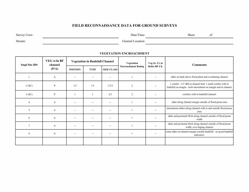
Survey Crew: Date/Time: Sheet of
Stream: General Location:
Vegetation in Bankfull Channel
POSTION TYPE SIZE CLASS
1 A -- -- -- 1 --
2 (SC) P 1/2 1/5 1/2/3 2 --
3 (SC) P 1 1 2/3 2 --
4 A -- -- -- 1 --
5 A -- -- -- 1 --
6 A -- -- -- 1 --
7 A -- -- -- 1 --
8 A -- -- -- 1 --
Comments
VEGETATION ENCROACHMENT
FIELD RECONNAISSANCE DATA FOR GROUND SURVEYS
Smpl Site ID# VEG w/in BF
channel (P/A)
Vegetation Encroachment Rating
Veg Sz. Cl. in Relict BF Ch.
alder on bank above flood plain and overhaning channel
1 conifer ~12" dbh in channel bed; 1 small conifer with in bankfull on margin - herb intermittent on margin and in channel
conifers with in bankfull channel
alder along channel margin outside of flood prone area
intermittent alders along channel with in and outside flood prone area
alder and perennial Herb along channel outside of flood prone width
alder and perennial Herb along channel outside of flood prone width, over haging channel
some alder on channel margin outside bankfull - no good bankfull indicators.
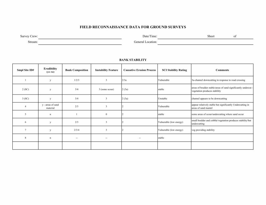
Survey Crew: Date/Time: Sheet of
Stream: General Location:
Smpl Site ID# Erodibility (yes /no)
Bank Composition Instability Feature Causative Erosion Process SCI Stability Rating Comments
1 y 1/2/3 3 2/3a Vulnerable 3a-channel downcutting in response to road crossing
2 (SC) y 3/4 3 (some scour) 2 (3a) stable areas of boulder stable/areas of sand significantly undercut - vegetation produces stability
3 (SC) y 3/4 3 2 (3a) Unstable channel appears to be downcutting
4 y - areas of sand material 2/3 3 2 Vulnerable appear relatively stable but significantly Undercutting in
areas of sand mantel
5 n 1 0 2 stable some areas of scour/undercutting where sand occur
6 y 2/3 3 2 Vulnerable (low energy) small boulder and cobble/vegetation produces stability/but undercutting
7 y 2/3/4 3 2 Vulnerable (low energy) veg providing stability
8 n -- -- -- stable
FIELD RECONNAISSANCE DATA FOR GROUND SURVEYS
BANK STABILITY
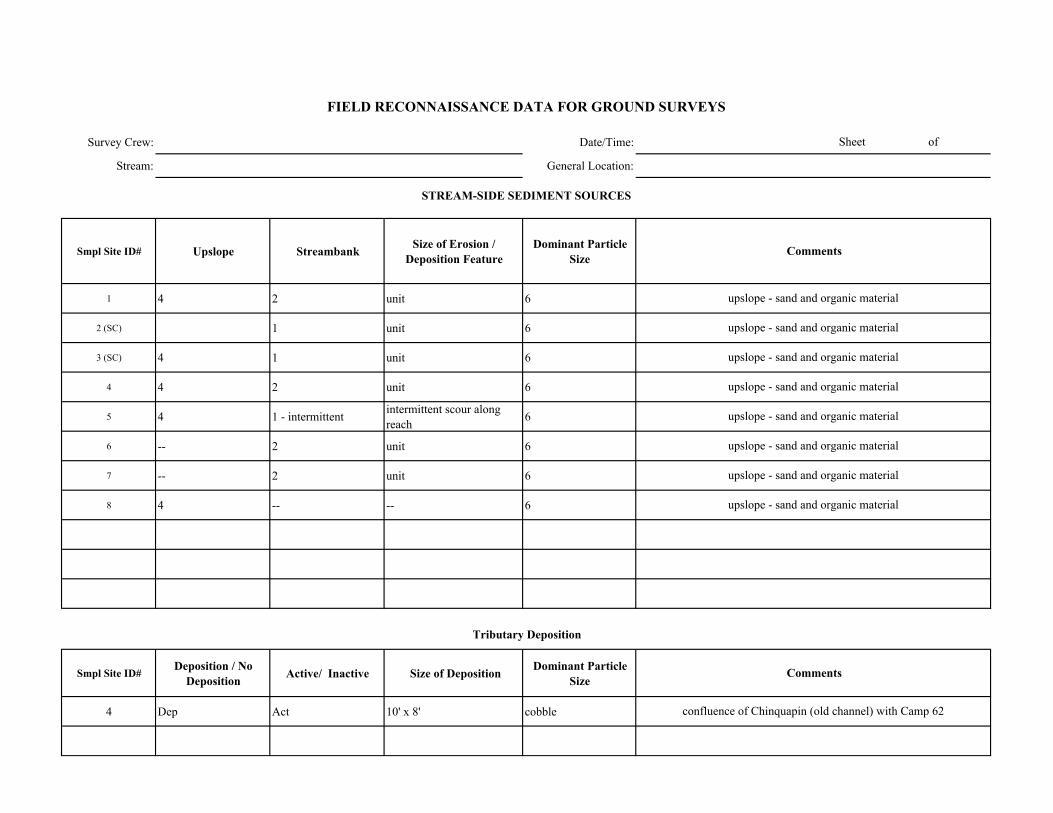
Survey Crew: Date/Time:
Stream: General Location:
Smpl Site ID# Upslope Streambank Size of Erosion / Deposition Feature
Dominant Particle Size
1 4 2 unit 6
2 (SC) 1 unit 6
3 (SC) 4 1 unit 6
4 4 2 unit 6
5 4 1 - intermittent intermittent scour along reach 6
6 -- 2 unit 6
7 -- 2 unit 6
8 4 -- -- 6
Smpl Site ID# Deposition / No Deposition Active/ Inactive Size of Deposition Dominant Particle
Size
4 Dep Act 10' x 8' cobble confluence of Chinquapin (old channel) with Camp 62
upslope - sand and organic material
upslope - sand and organic material
upslope - sand and organic material
upslope - sand and organic material
Sheet of
FIELD RECONNAISSANCE DATA FOR GROUND SURVEYS
Comments
Tributary Deposition
STREAM-SIDE SEDIMENT SOURCES
Comments
upslope - sand and organic material
upslope - sand and organic material
upslope - sand and organic material
upslope - sand and organic material

Survey Crew: Date/Time: Sheet of
Stream: General Location:
Smpl Site ID# Presence / Absence Low Flow BF FP Geomorphic Function Recruitment Potential
(High / Moderate / Low)Comments
1 A -- -- -- -- H trees/undercut/ moderate Slopes - abundant SWD
2 (SC) A -- -- -- -- M very low slope but trees abundant
3 (SC) A -- -- -- -- M very low slope but trees abundant
4 P x x x 6 M some trees and relatively steep slope
5 P-2pieces x x x 6 H relatively steep slopes abundant Trees
6 P -1piece x x x 6 M Abundant trees but low slope
7 P few pieces x x x 6 M Abundant trees but low slope
8 P x x x 3/6 M steep slopes but not many trees near channel
FIELD RECONNAISSANCE DATA FOR GROUND SURVEYS
LARGE WOODY DEBRIS
Channel Zone
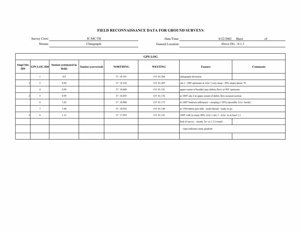
Date/Time: 8/22/2002 Sheet of
General Location:
Smpl Site ID# GPS LOG ID# Station (estimated in
field) Station (corrected) NORTHING WESTING Feature Comments
1 0.8 37 18.191 119 01.204 chinquapin diversion
1 2 0.84 37 18.142 119 01.205 site 1 ~200' upstream in A2a+ (very steep ~30% slope) photo 70
4 0.98 37 18.060 119 01.191 upper extent of boulder jam (debris flow) at 985' upstream
2 5 0.99 37 18.055 119 01.176 at 1005' site 2 in upper extent of debris flow scoured section
6 1.03 37 18.008 119 01.173 at 1005' bedrock inflouence - steeping (>30%) (possible A1a+ break)
7 1.06 37 18.016 119 01.140 at 1394 debris jam falls - multi-thread - ready to go
3 8 1.12 37 17.959 119 01.141 1689' with in steep (40% A2a+) site 3 - A2a+ to at least 1.2
End of survey - clearly 2a+ to 1.2 (visual)
FIELD RECONNAISSANCE DATA FOR GROUND SURVEYS
JC/MC/TB
Chinquapin Above Div. .8-1.3
- topo indicates same gradient
GPS LOG
Survey Crew:
Stream:
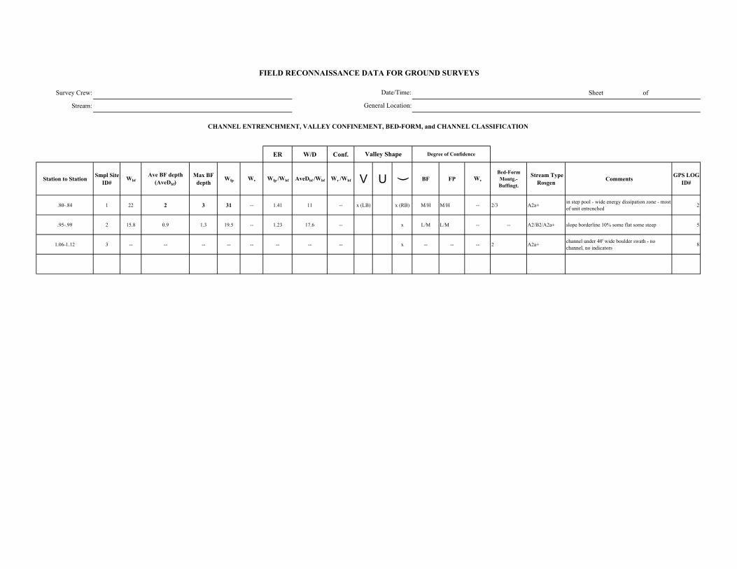
Survey Crew: Sheet of
Stream:
ER W/D Conf.
Station to Station Smpl Site ID#
WbfAve BF depth
(AveDbf)Max BF
depthWfp Wv Wfp /Wbf AveDbf /Wbf Wv /Wbf V U ( BF FP Wv
Bed-Form Montg.-Buffingt.
Stream Type Rosgen Comments GPS LOG
ID#
.80-.84 1 22 2 3 31 -- 1.41 11 -- x (LB) x (RB) M/H M/H -- 2/3 A2a+ in step pool - wide energy dissipation zone - most of unit entrenched 2
.95-.99 2 15.8 0.9 1.3 19.5 -- 1.23 17.6 -- x L/M L/M -- -- A2/B2/A2a+ slope borderline 10% some flat some steep 5
1.06-1.12 3 -- -- -- -- -- -- -- -- x -- -- -- 2 A2a+ channel under 40' wide boulder swath - no channel, no indicators 8
FIELD RECONNAISSANCE DATA FOR GROUND SURVEYS
Degree of Confidence
CHANNEL ENTRENCHMENT, VALLEY CONFINEMENT, BED-FORM, and CHANNEL CLASSIFICATION
Valley Shape
Date/Time:
General Location:
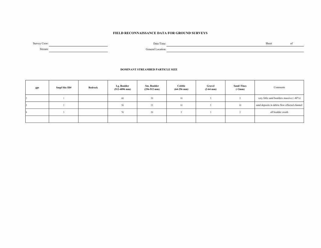
Date/Time:
General Location:
DOMINANT STREAMBED PARTICLE SIZE
gps Smpl Site ID# Bedrock Lg. Boulder (512-4096 mm)
Sm. Boulder (256-512 mm)
Cobble (64-256 mm)
Gravel (2-64 mm)
Sand/ Fines (<2mm)
2 1 60 20 10 5 5
5 2 50 25 10 5 10
8 3 70 20 5 3 2
Survey Crew:
Stream:
sand deposits in debris flow effected channel
all boulder swath
FIELD RECONNAISSANCE DATA FOR GROUND SURVEYS
Sheet of
Comments
very little sand boulders massive (~40"x)
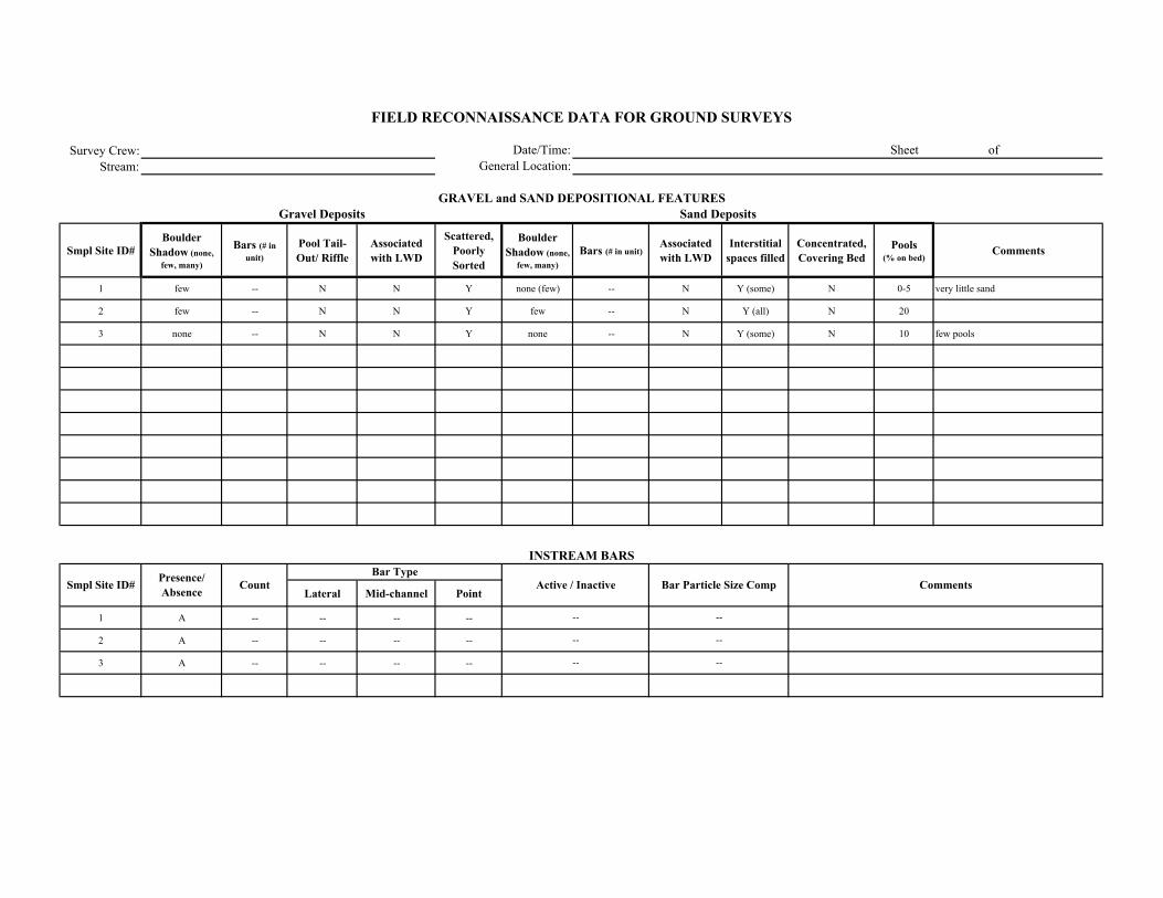
Survey Crew:Stream:
Smpl Site ID# Boulder
Shadow (none, few, many)
Bars (# in unit)
Pool Tail-Out/ Riffle
Associated with LWD
Scattered, Poorly Sorted
Boulder Shadow (none,
few, many)Bars (# in unit)
Associated with LWD
Interstitial spaces filled
Concentrated, Covering Bed
Pools (% on bed)
Comments
1 few -- N N Y none (few) -- N Y (some) N 0-5 very little sand
2 few -- N N Y few -- N Y (all) N 20
3 none -- N N Y none -- N Y (some) N 10 few pools
Lateral Mid-channel Point
1 A -- -- -- --
2 A -- -- -- --
3 A -- -- -- --
--
--
--
--
--
--
FIELD RECONNAISSANCE DATA FOR GROUND SURVEYS
Date/Time:General Location:
Sheet of
GRAVEL and SAND DEPOSITIONAL FEATURESGravel Deposits
Smpl Site ID# Comments
Sand Deposits
INSTREAM BARS
Presence/ Absence Count Active / Inactive Bar Particle Size Comp
Bar Type
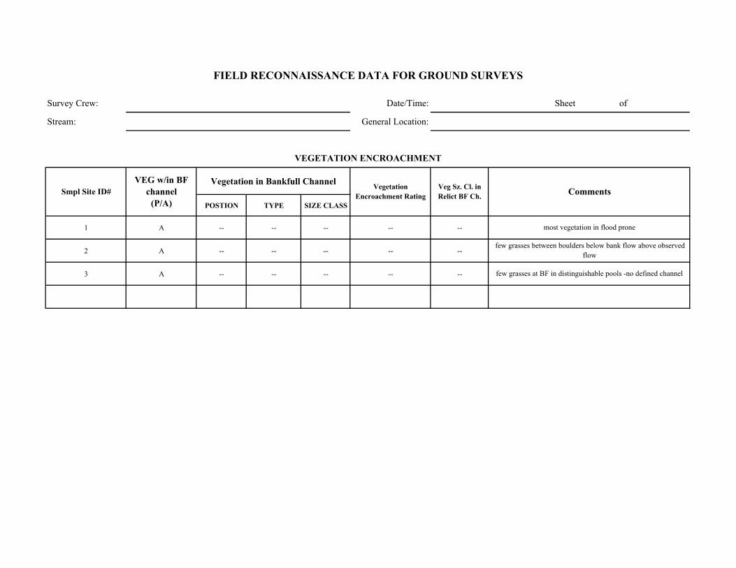
Survey Crew: Date/Time: Sheet of
Stream: General Location:
Vegetation in Bankfull Channel
POSTION TYPE SIZE CLASS
1 A -- -- -- -- --
2 A -- -- -- -- --
3 A -- -- -- -- --
most vegetation in flood prone
few grasses between boulders below bank flow above observed flow
few grasses at BF in distinguishable pools -no defined channel
Comments
VEGETATION ENCROACHMENT
FIELD RECONNAISSANCE DATA FOR GROUND SURVEYS
Smpl Site ID# VEG w/in BF
channel (P/A)
Vegetation Encroachment Rating
Veg Sz. Cl. in Relict BF Ch.
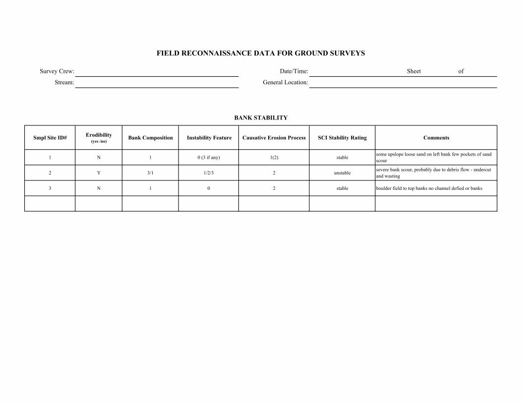
Survey Crew: Date/Time: Sheet of
Stream: General Location:
Smpl Site ID# Erodibility (yes /no)
Bank Composition Instability Feature Causative Erosion Process SCI Stability Rating Comments
1 N 1 0 (3 if any) 1(2) stable some upslope loose sand on left bank few pockets of sand scour
2 Y 3/1 1/2/3 2 unstable severe bank scour, probably due to debris flow - undercut and wasting
3 N 1 0 2 stable boulder field to top banks no channel defied or banks
FIELD RECONNAISSANCE DATA FOR GROUND SURVEYS
BANK STABILITY
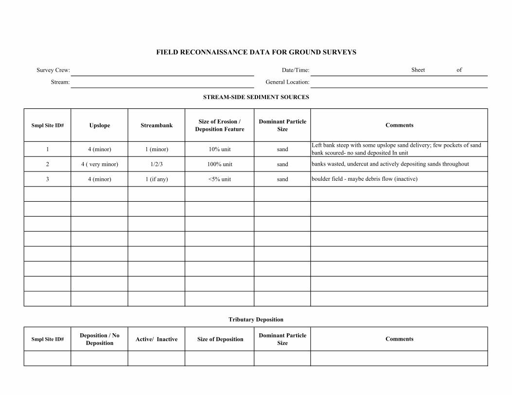
Survey Crew: Date/Time:
Stream: General Location:
Smpl Site ID# Upslope Streambank Size of Erosion / Deposition Feature
Dominant Particle Size
1 4 (minor) 1 (minor) 10% unit sand
2 4 ( very minor) 1/2/3 100% unit sand
3 4 (minor) 1 (if any) <5% unit sand
Smpl Site ID# Deposition / No
Deposition Active/ Inactive Size of Deposition Dominant Particle Size
Sheet of
FIELD RECONNAISSANCE DATA FOR GROUND SURVEYS
Comments
Tributary Deposition
STREAM-SIDE SEDIMENT SOURCES
Comments
Left bank steep with some upslope sand delivery; few pockets of sand bank scoured- no sand deposited In unit
banks wasted, undercut and actively depositing sands throughout
boulder field - maybe debris flow (inactive)
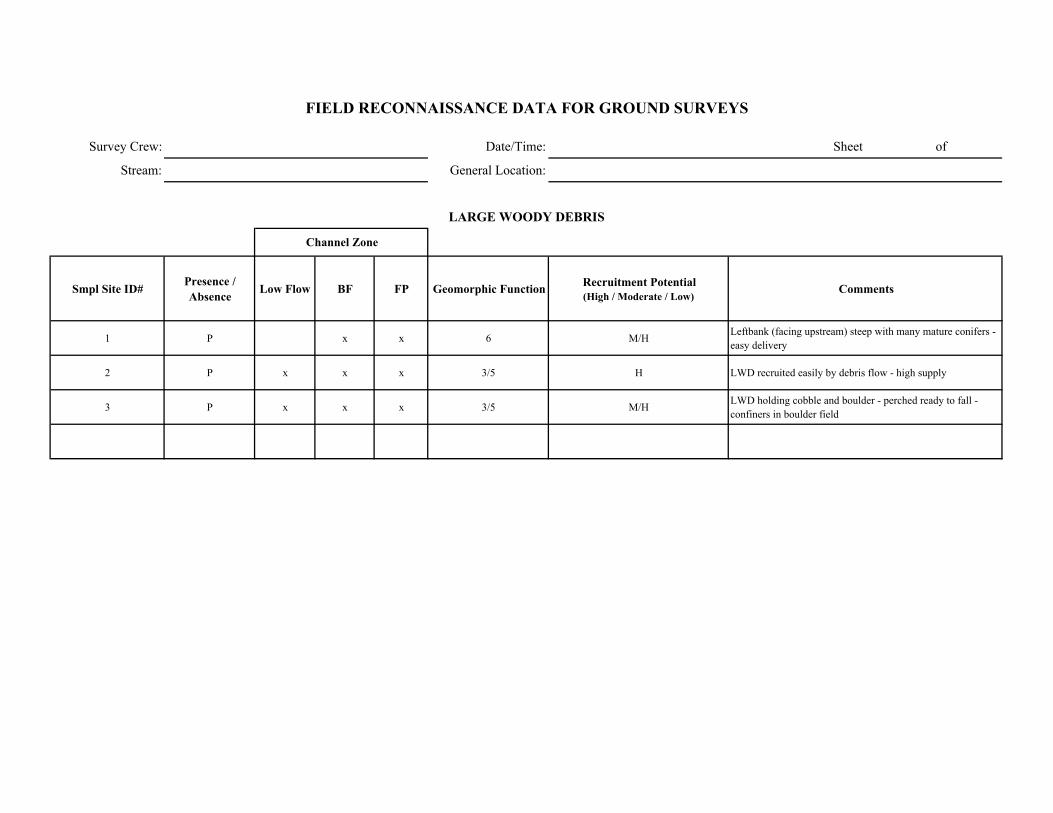
Survey Crew: Date/Time: Sheet of
Stream: General Location:
Smpl Site ID# Presence / Absence Low Flow BF FP Geomorphic Function Recruitment Potential
(High / Moderate / Low)Comments
1 P x x 6 M/H Leftbank (facing upstream) steep with many mature conifers - easy delivery
2 P x x x 3/5 H LWD recruited easily by debris flow - high supply
3 P x x x 3/5 M/H LWD holding cobble and boulder - perched ready to fall - confiners in boulder field
FIELD RECONNAISSANCE DATA FOR GROUND SURVEYS
LARGE WOODY DEBRIS
Channel Zone
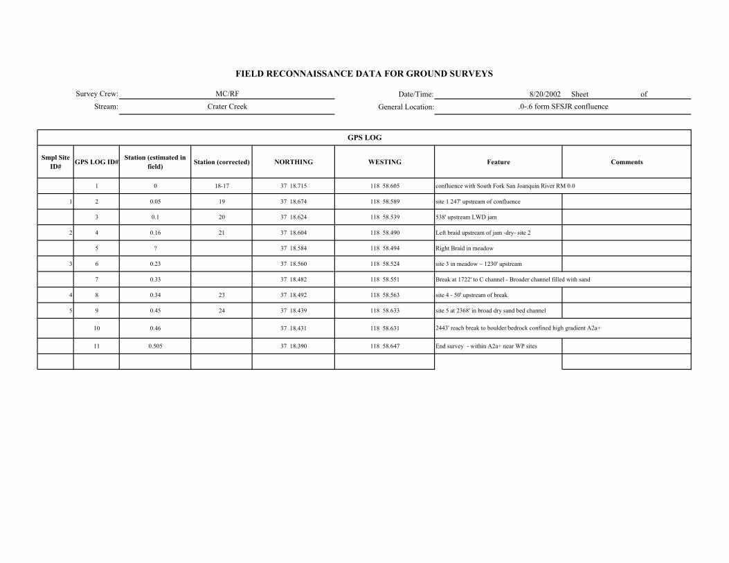
Date/Time: 8/20/2002 Sheet of
General Location:
Smpl Site ID# GPS LOG ID# Station (estimated in
field) Station (corrected) NORTHING WESTING Feature Comments
1 0 18-17 37 18.715 118 58.605 confluence with South Fork San Joanquin River RM 0.0
1 2 0.05 19 37 18.674 118 58.589 site 1 247' upstream of confluence
3 0.1 20 37 18.624 118 58.539 538' upstream LWD jam
2 4 0.16 21 37 18.604 118 58.490 Left braid upstream of jam -dry- site 2
5 ? 37 18.584 118 58.494 Right Braid in meadow
3 6 0.23 37 18.560 118 58.524 site 3 in meadow ~ 1230' upstream
7 0.33 37 18.482 118 58.551 Break at 1722' to C channel - Broader channel filled with sand
4 8 0.34 23 37 18.492 118 58.563 site 4 - 50' upstream of break
5 9 0.45 24 37 18.439 118 58.633 site 5 at 2368' in broad dry sand bed channel
10 0.46 37 18.431 118 58.631
11 0.505 37 18.390 118 58.647 End survey - within A2a+ near WP sites
2443' reach break to boulder/bedrock confined high gradient A2a+
GPS LOG
Survey Crew:
Stream:
FIELD RECONNAISSANCE DATA FOR GROUND SURVEYS
MC/RF
Crater Creek .0-.6 form SFSJR confluence
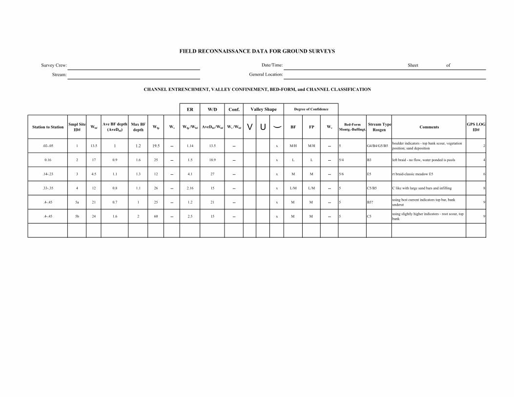
Survey Crew: Sheet of
Stream:
ER W/D Conf.
Station to Station Smpl Site ID#
WbfAve BF depth
(AveDbf)Max BF
depthWfp Wv Wfp /Wbf AveDbf /Wbf Wv /Wbf V U ( BF FP Wv
Bed-Form Montg.-Buffingt.
Stream Type Rosgen Comments GPS LOG
ID#
.02-.05 1 13.5 1 1.2 19.5 -- 1.14 13.5 -- x M/H M/H -- 5 G4/B4/G5/B5boulder indicators - top bank scour, vegetation position; sand deposition 2
0.16 2 17 0.9 1.6 25 -- 1.5 18.9 -- x L L -- 5/4 B3 left braid - no flow, water ponded is pools 4
.14-.23 3 4.5 1.1 1.3 12 -- 4.1 27 -- x M M -- 5/6 E5 rt braid-classic meadow E5 6
.33-.35 4 12 0.8 1.1 26 -- 2.16 15 -- x L/M L/M -- 5 C5/B5 C like with large sand bars and infilling 8
.4-.45 5a 21 0.7 1 25 -- 1.2 21 -- x M M -- 5 B5?using best current indicators top bar, bank underut 9
.4-.45 5b 24 1.6 2 60 -- 2.5 15 -- x M M -- 5 C5 using slightly higher indicators - root scour, top bank 9
FIELD RECONNAISSANCE DATA FOR GROUND SURVEYS
Degree of Confidence
CHANNEL ENTRENCHMENT, VALLEY CONFINEMENT, BED-FORM, and CHANNEL CLASSIFICATION
Valley Shape
Date/Time:
General Location:

Date/Time:
General Location:
DOMINANT STREAMBED PARTICLE SIZE
gps Smpl Site ID# Bedrock Lg. Boulder (512-4096 mm)
Sm. Boulder (256-512 mm)
Cobble (64-256 mm)
Gravel (2-64 mm)
Sand/ Fines (<2mm)
2 1 5 5 10 5 40 35
4 2 -- -- 10 50 20 10
6 3 -- -- -- -- -- 100
8 4 -- -- -- -- -- 100
9 5 -- -- -- -- 10 90
FIELD RECONNAISSANCE DATA FOR GROUND SURVEYS
Sheet of
Comments
all sand
all sand
gravel is small size
Survey Crew:
Stream:
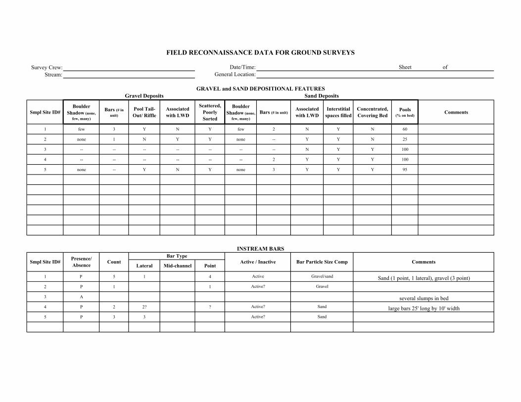
Survey Crew:Stream:
Smpl Site ID# Boulder
Shadow (none, few, many)
Bars (# in unit)
Pool Tail-Out/ Riffle
Associated with LWD
Scattered, Poorly Sorted
Boulder Shadow (none,
few, many)Bars (# in unit)
Associated with LWD
Interstitial spaces filled
Concentrated, Covering Bed
Pools (% on bed)
Comments
1 few 3 Y N Y few 2 N Y N 60
2 none 1 N Y Y none -- Y Y N 25
3 -- -- -- -- -- -- -- N Y Y 100
4 -- -- -- -- -- -- 2 Y Y Y 100
5 none -- Y N Y none 3 Y Y Y 95
Lateral Mid-channel Point
1 P 5 1 4
2 P 1 1
3 A
4 P 2 2? ?
5 P 3 3
Comments
Sand Deposits
INSTREAM BARS
Presence/ Absence Count Active / Inactive Bar Particle Size Comp
Bar Type
FIELD RECONNAISSANCE DATA FOR GROUND SURVEYS
Date/Time:General Location:
Sheet of
GRAVEL and SAND DEPOSITIONAL FEATURESGravel Deposits
Smpl Site ID#
Sand (1 point, 1 lateral), gravel (3 point)
several slumps in bed
large bars 25' long by 10' width
Gravel/sand
Gravel
Sand
SandActive?
Active
Active?
Active?
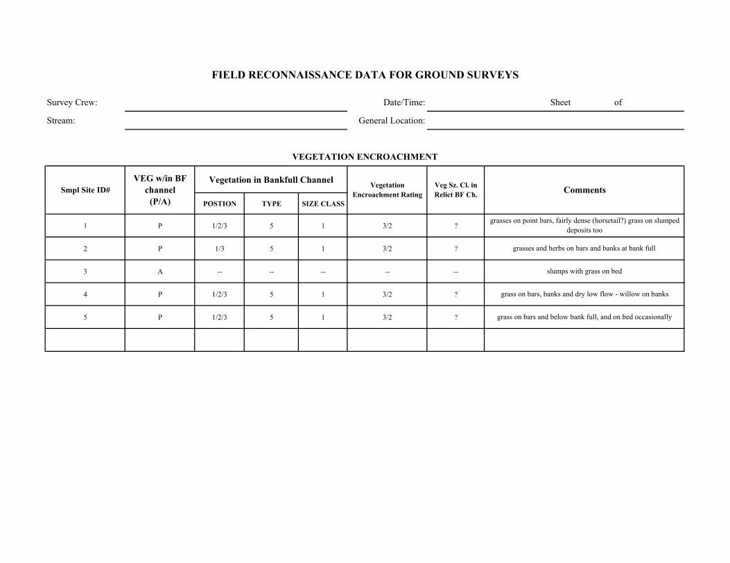
Survey Crew: Date/Time: Sheet of
Stream: General Location:
Vegetation in Bankfull Channel
POSTION TYPE SIZE CLASS
1 P 1/2/3 5 1 3/2 ?
2 P 1/3 5 1 3/2 ?
3 A -- -- -- -- --
4 P 1/2/3 5 1 3/2 ?
5 P 1/2/3 5 1 3/2 ?
Comments
VEGETATION ENCROACHMENT
FIELD RECONNAISSANCE DATA FOR GROUND SURVEYS
Smpl Site ID# VEG w/in BF
channel (P/A)
Vegetation Encroachment Rating
Veg Sz. Cl. in Relict BF Ch.
grasses on point bars, fairly dense (horsetail?) grass on slumped deposits too
grasses and herbs on bars and banks at bank full
slumps with grass on bed
grass on bars, banks and dry low flow - willow on banks
grass on bars and below bank full, and on bed occasionally
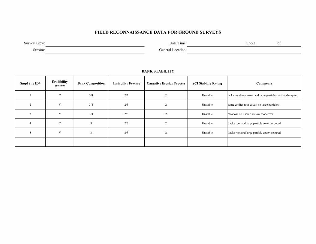
Survey Crew: Date/Time: Sheet of
Stream: General Location:
Smpl Site ID# Erodibility (yes /no)
Bank Composition Instability Feature Causative Erosion Process SCI Stability Rating Comments
1 Y 3/4 2/3 2 Unstable lacks good root cover and large particles, active slumping
2 Y 3/4 2/3 2 Unstable some conifer root cover, no large particles
3 Y 3/4 2/3 2 Unstable meadow E5 - some willow root cover
4 Y 3 2/3 2 Unstable Lacks root and large particle cover; scoured
5 Y 3 2/3 2 Unstable Lacks root and large particle cover; scoured
FIELD RECONNAISSANCE DATA FOR GROUND SURVEYS
BANK STABILITY

Survey Crew: Date/Time:
Stream: General Location:
Smpl Site ID# Upslope Streambank Size of Erosion / Deposition Feature
Dominant Particle Size
1 1/2/3 Unit 6
2 1/2/3 Unit 6
3 1/2/3 Unit 6
4 1/2/3 Unit 6
5 1/2/3 Unit 6
Smpl Site ID# Deposition / No
Deposition Active/ Inactive Size of Deposition Dominant Particle Size
Sheet of
FIELD RECONNAISSANCE DATA FOR GROUND SURVEYS
Comments
Tributary Deposition
STREAM-SIDE SEDIMENT SOURCES
Comments
sand banks undercut and slumping opposite point bars
sand banks undercut and slumping opposite point bars
slumping throughout
slumping and scour/undercut throughout
slumping and scour/undercut throughout
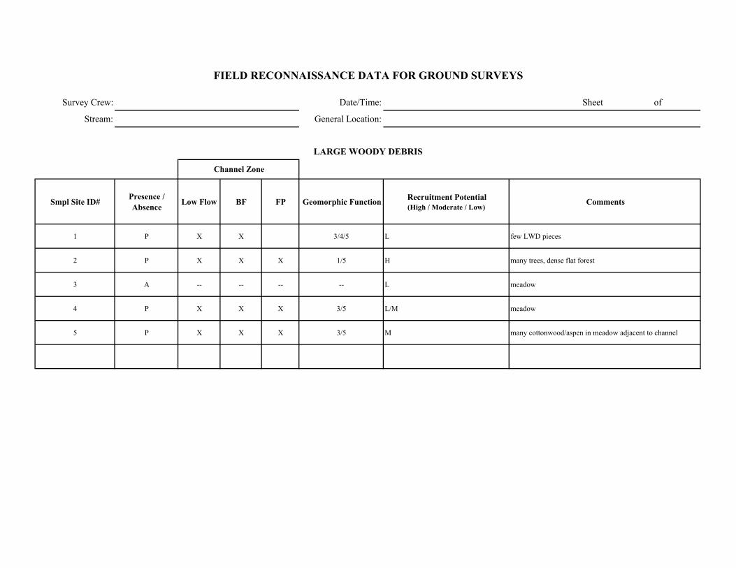
Survey Crew: Date/Time: Sheet of
Stream: General Location:
Smpl Site ID# Presence / Absence Low Flow BF FP Geomorphic Function Recruitment Potential
(High / Moderate / Low)Comments
1 P X X 3/4/5 L few LWD pieces
2 P X X X 1/5 H many trees, dense flat forest
3 A -- -- -- -- L meadow
4 P X X X 3/5 L/M meadow
5 P X X X 3/5 M many cottonwood/aspen in meadow adjacent to channel
FIELD RECONNAISSANCE DATA FOR GROUND SURVEYS
LARGE WOODY DEBRIS
Channel Zone
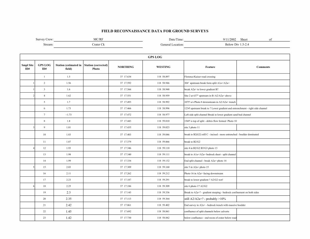
Date/Time: 9/11/2002 Sheet of General Location:
Smpl Site ID#
GPS LOG ID#
Station (estimated in field)
Station (corrected) Photo NORTHING WESTING Feature Comments
1 1.5 37 17.634 118 58.897 Florence/Kaiser road crossing
1 2 1.56 37 17.592 118 58.946 304' upstream break form split A1a+/A2a+
1 3 1.6 37 17.566 118 58.948 break A2a+ to lower gradient B?
2 4 1.62 37 17.551 118 58.959 Site 2 at 637" upstream in B /A2/A2a+ above
5 1.7 37 17.493 118 58.992 1075' u/s Photo 8 downstream in A2/A2a+ trench
6 1.73 37 17.466 118 58.996 1234' upstream break to ? Lower gradient and entrenchment - right side channel
7 ~1.73 37 17.472 118 58.977 Left side split channel Break to lower gradient sand bed channel
8 1.8 37 17.443 118 59.010 1569' is top of split - debris flow formed Photo 10
3 9 1.81 37 17.435 118 59.023 site 3 photo 11
10 1.83 37 17.403 118 59.046
11 1.87 37 17.379 118 59.066 break to B2/G2
4 12 1.93 37 17.346 118 59.110 site 4 in B2/G2 B3/G3 photo 13
13 1.98 37 17.340 118 59.111 break to A1a+/A2a+ bedrock sheet - split channel
14 1.99 37 17.334 118 59.132 End split channel - break A2a+ photo 14
5 15 2.03 37 17.309 118 59.160 site 5 in A2a+ photo 15
16 2.11 37 17.262 118 59.212 Photo 16 in A2a+ facing downstream
17 2.23 37 17.187 118 59.291 break to lower gradient ? A2/G2 wet!
6 18 2.25 37 17.186 118 59.309 site 6 photo 17 A2/G2
19 2.3 37 17.145 118 59.336 Break to A2a+? - gradient steeping - bedrock confinement on both sides
20 2.35 37 17.113 118 59.364 still A2/A2a+? - probably >10%
21 2.42 37 17.061 118 59.402 End survey in A2a+ - bedrock trench with massive boulder
22 1.45 37 17.692 118 58.841 confluence of split channels below culverts
23 1.42 37 17.730 118 58.842 below confluence - end recon of crater below road
FIELD RECONNAISSANCE DATA FOR GROUND SURVEYS
MC/RFCrater Ck Below Div 1.5-2.4
break to B2(G2) still C - incised - more entrenched - boulder dominated
GPS LOG
Survey Crew:Stream:
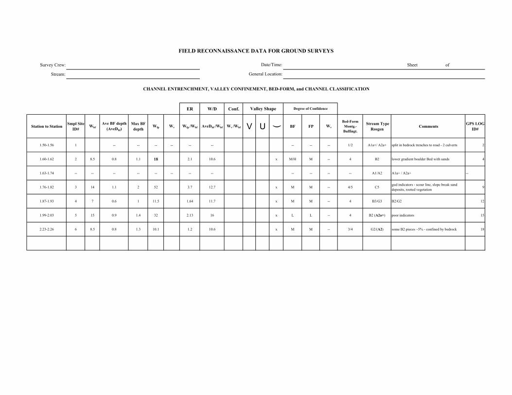
Survey Crew: Sheet of
Stream:
ER W/D Conf.
Station to Station Smpl Site ID#
WbfAve BF depth
(AveDbf)Max BF
depthWfp Wv Wfp /Wbf AveDbf /Wbf Wv /Wbf V U ( BF FP Wv
Bed-Form Montg.-Buffingt.
Stream Type Rosgen Comments GPS LOG
ID#
1.50-1.56 1 -- -- -- -- -- -- -- -- -- 1/2 A1a+/ A2a+ split in bedrock trenches to road - 2 culverts 2
1.60-1.62 2 8.5 0.8 1.1 18 2.1 10.6 x M/H M -- 4 B2 lower gradient boulder Bed with sands 4
1.63-1.74 -- -- -- -- -- -- -- -- -- -- -- -- A1/A2 A1a+ / A2a+ --
1.76-1.82 3 14 1.1 2 52 3.7 12.7 x M M -- 4/5 C5god indicators - scour line, slope break sand deposits, rooted vegetation 9
1.87-1.93 4 7 0.6 1 11.5 1.64 11.7 x M M -- 4 B3/G3 B2/G2 12
1.99-2.03 5 15 0.9 1.4 32 2.13 16 x L L -- 4 B2 (A2a+) poor indicators 15
2.23-2.26 6 8.5 0.8 1.3 10.1 1.2 10.6 x M M -- 3/4 G2/(A2) some B2 pieces ~5% - confined by bedrock 18
FIELD RECONNAISSANCE DATA FOR GROUND SURVEYS
Degree of Confidence
CHANNEL ENTRENCHMENT, VALLEY CONFINEMENT, BED-FORM, and CHANNEL CLASSIFICATION
Valley Shape
Date/Time:
General Location:
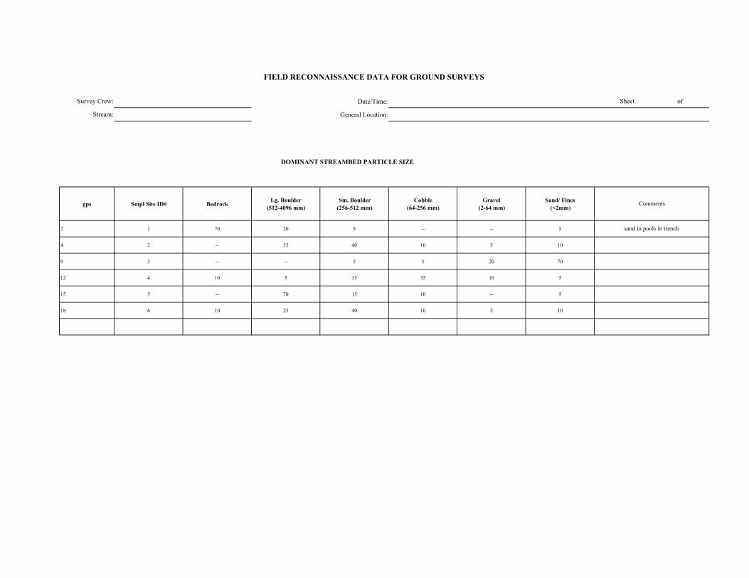
Date/Time:
General Location:
DOMINANT STREAMBED PARTICLE SIZE
gps Smpl Site ID# Bedrock Lg. Boulder (512-4096 mm)
Sm. Boulder (256-512 mm)
Cobble (64-256 mm)
Gravel (2-64 mm)
Sand/ Fines (<2mm)
2 1 70 20 5 -- -- 5
4 2 -- 35 40 10 5 10
9 3 -- -- 5 5 20 70
12 4 10 5 35 35 10 5
15 5 -- 70 15 10 -- 5
18 6 10 25 40 10 5 10
Survey Crew:
Stream:
FIELD RECONNAISSANCE DATA FOR GROUND SURVEYS
Sheet of
Comments
sand in pools in trench

Survey Crew:Stream:
Smpl Site ID# Boulder
Shadow (none, few, many)
Bars (# in unit)
Pool Tail-Out/ Riffle
Associated with LWD
Scattered, Poorly Sorted
Boulder Shadow (none,
few, many)Bars (# in unit)
Associated with LWD
Interstitial spaces filled
Concentrated, Covering Bed
Pools (% on bed)
Comments
1 none -- N N N few -- N N N 50 sand in few pools
2 none -- N N Y few -- N Y N 25 sand mostly interstitial
3 none -- Y N Y few -- N Y Y 75
4 none -- Y Y (some) Y none -- Y Y N 25
5 none -- N N Y few -- N Y N 10 sand in pockets
6 none -- N N Y few -- N Y N 30
Lateral Mid-channel Point
1 A -- -- -- --
2 A -- -- -- --
3 A -- -- -- --
4 A -- -- -- --
5 A -- -- -- --
6 A -- -- -- --
--
--
--
--
--
--
--
--
--
--
--
--
FIELD RECONNAISSANCE DATA FOR GROUND SURVEYS
Date/Time:General Location:
Sheet of
GRAVEL and SAND DEPOSITIONAL FEATURESGravel Deposits
Smpl Site ID# Comments
Sand Deposits
INSTREAM BARS
Presence/ Absence Count Active / Inactive Bar Particle Size Comp
Bar Type
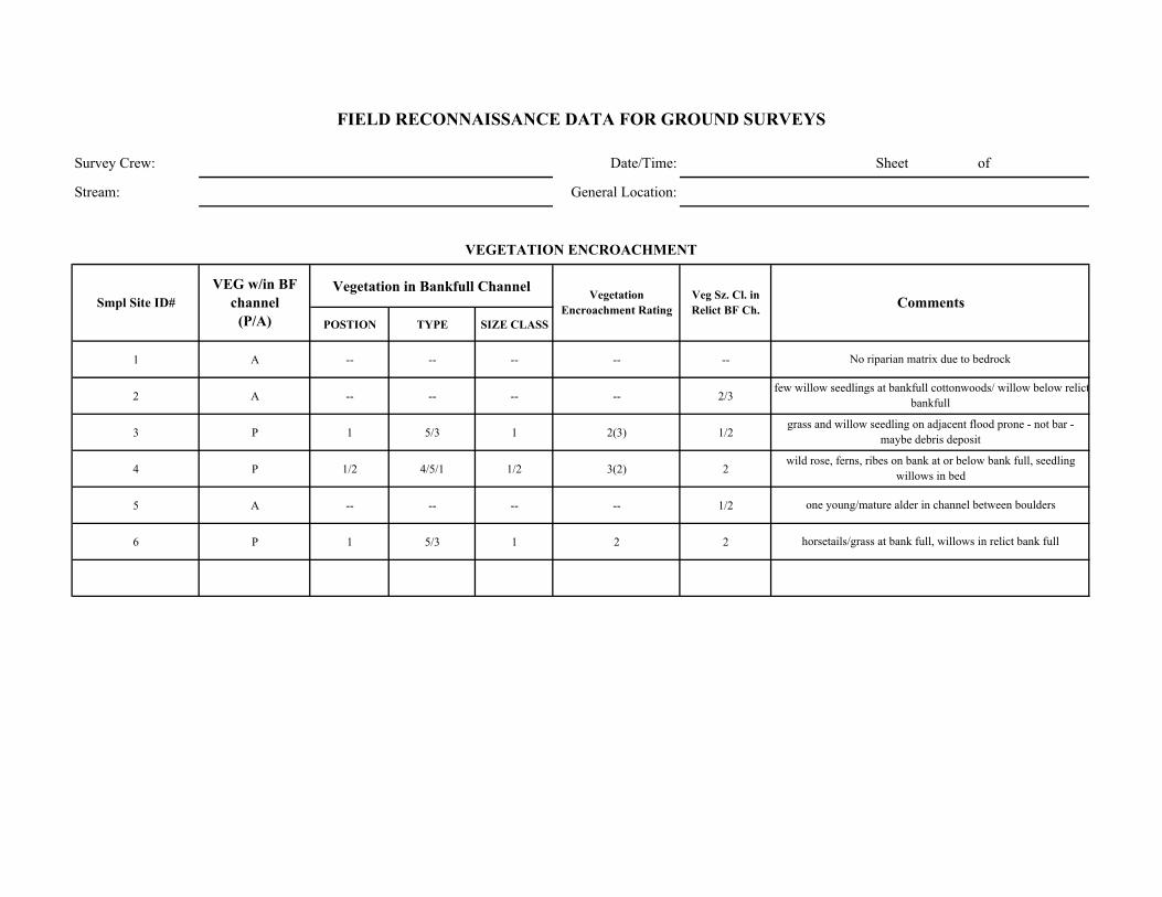
Survey Crew: Date/Time: Sheet of
Stream: General Location:
Vegetation in Bankfull Channel
POSTION TYPE SIZE CLASS
1 A -- -- -- -- --
2 A -- -- -- -- 2/3
3 P 1 5/3 1 2(3) 1/2
4 P 1/2 4/5/1 1/2 3(2) 2
5 A -- -- -- -- 1/2
6 P 1 5/3 1 2 2
one young/mature alder in channel between boulders
horsetails/grass at bank full, willows in relict bank full
No riparian matrix due to bedrock
few willow seedlings at bankfull cottonwoods/ willow below relictbankfull
grass and willow seedling on adjacent flood prone - not bar - maybe debris deposit
wild rose, ferns, ribes on bank at or below bank full, seedling willows in bed
Comments
VEGETATION ENCROACHMENT
FIELD RECONNAISSANCE DATA FOR GROUND SURVEYS
Smpl Site ID# VEG w/in BF
channel (P/A)
Vegetation Encroachment Rating
Veg Sz. Cl. in Relict BF Ch.
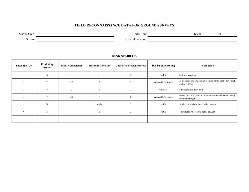
Survey Crew: Date/Time: Sheet of
Stream: General Location:
Smpl Site ID# Erodibility (yes /no)
Bank Composition Instability Feature Causative Erosion Process SCI Stability Rating Comments
1 N 1 0 2 stable bedrock trenches
2 Y 3/2 3 2 vulnerable/unstable some scour and undercut, but much of the banks have rock and root cover
3 Y 3 3 2 unstable all undercut and scoured
4 Y 3/2 3 2 vulnerable/unstable roots/LWD and small boulder cover on most banks - many scoured through
5 N 1 0 (3) 2 stable Slight scour where sand banks present
6 N 1 3 2 stable Vulnerable where sand banks present
FIELD RECONNAISSANCE DATA FOR GROUND SURVEYS
BANK STABILITY
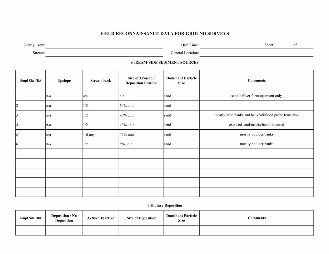
Survey Crew: Date/Time:
Stream: General Location:
Smpl Site ID# Upslope Streambank Size of Erosion / Deposition Feature
Dominant Particle Size
1 n/a n/a n/a sand
2 n/a 1/2 50% unit sand
3 n/a 1/2 90% unit sand
4 n/a 1/2 40% unit sand
5 n/a 1 if any <5% unit sand
6 n/a 1/2 5% unit sand
Smpl Site ID# Deposition / No
Deposition Active/ Inactive Size of Deposition Dominant Particle Size
mostly boulder banks
mostly boulder banks
Sheet of
FIELD RECONNAISSANCE DATA FOR GROUND SURVEYS
Comments
Tributary Deposition
STREAM-SIDE SEDIMENT SOURCES
Comments
sand deliver form upstream only
mostly sand banks and bankfull/flood prone transition
exposed sand matrix banks scoured
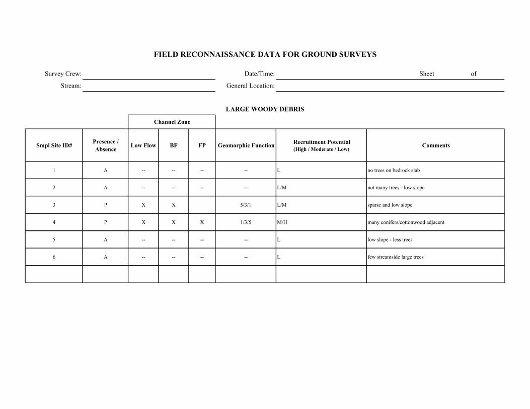
Survey Crew: Date/Time: Sheet of
Stream: General Location:
Smpl Site ID# Presence / Absence Low Flow BF FP Geomorphic Function Recruitment Potential
(High / Moderate / Low)Comments
1 A -- -- -- -- L no trees on bedrock slab
2 A -- -- -- -- L/M not many trees - low slope
3 P X X 5/3/1 L/M sparse and low slope
4 P X X X 1/3/5 M/H many conifers/cottonwood adjacent
5 A -- -- -- -- L low slope - less trees
6 A -- -- -- -- L few streamside large trees
FIELD RECONNAISSANCE DATA FOR GROUND SURVEYS
LARGE WOODY DEBRIS
Channel Zone
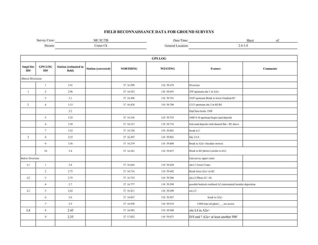
Date/Time: Sheet of General Location:
Smpl Site ID#
GPS LOG ID#
Station (estimated in field) Station (corrected) NORTHING WESTING Feature Comments
Above Diversion
1 2.91 37 16.599 118 59.678 Diversion
1 2 2.96 37 16.552 118 59.691 254' upstream site 1 in A2a+
3 3.1 37 16.496 118 59.761 1010' upstream Break to lower Gradient B?
2 4 3.13 37 16.428 118 59.780 1213' upstream site 2 in B2/B3
3.2 HipChain broke 1500'
5 3.25 37 16.336 118 59.755 1800' 0.34 upstream begin sand deposits
6 3.28 37 16.337 118 59.776 End sand deposits mid-channel Bar - B2 above
7 3.32 37 16.330 118 59.801 break to C
3 8 3.33 37 16.307 118 59.801 Site 3 C4
9 3.36 37 16.279 118 59.808 Break to A2a+ (boulder strewn)
10 3.4 37 16.241 118 59.827
Below Diversion End survey upper crater
L1 1 2.8 37 16.665 118 59.628 site L1 lower Crater
2 2.75 37 16.716 118 59.602 Break form A2a+ to B2
L2 3 2.75 37 16.752 118 59.586 site L2 Photo 63 - 64
4 2.7 37 16.777 118 59.598 possible bedrock confined A2 (entrenched) boulder deposition
L3 5 2.62 37 16.811 118 59.590 site L3
6 2.6 37 16.867 118 59.567 break to A2a+
7 2.5 37 16.930 118 59.519 LWD Jam (4) photo ___/no access
L4 8 2.45 37 16.943 118 59.500 site L4 in A2a+
9 2.35 37 17.052 118 59.471 D/S end ? A2a+ at least another 500'
Break to B2 photos (similar to d/s)
GPS LOG
Survey Crew:Stream:
FIELD RECONNAISSANCE DATA FOR GROUND SURVEYS
MC/JC/TBCrater Ck 2.4-3.4
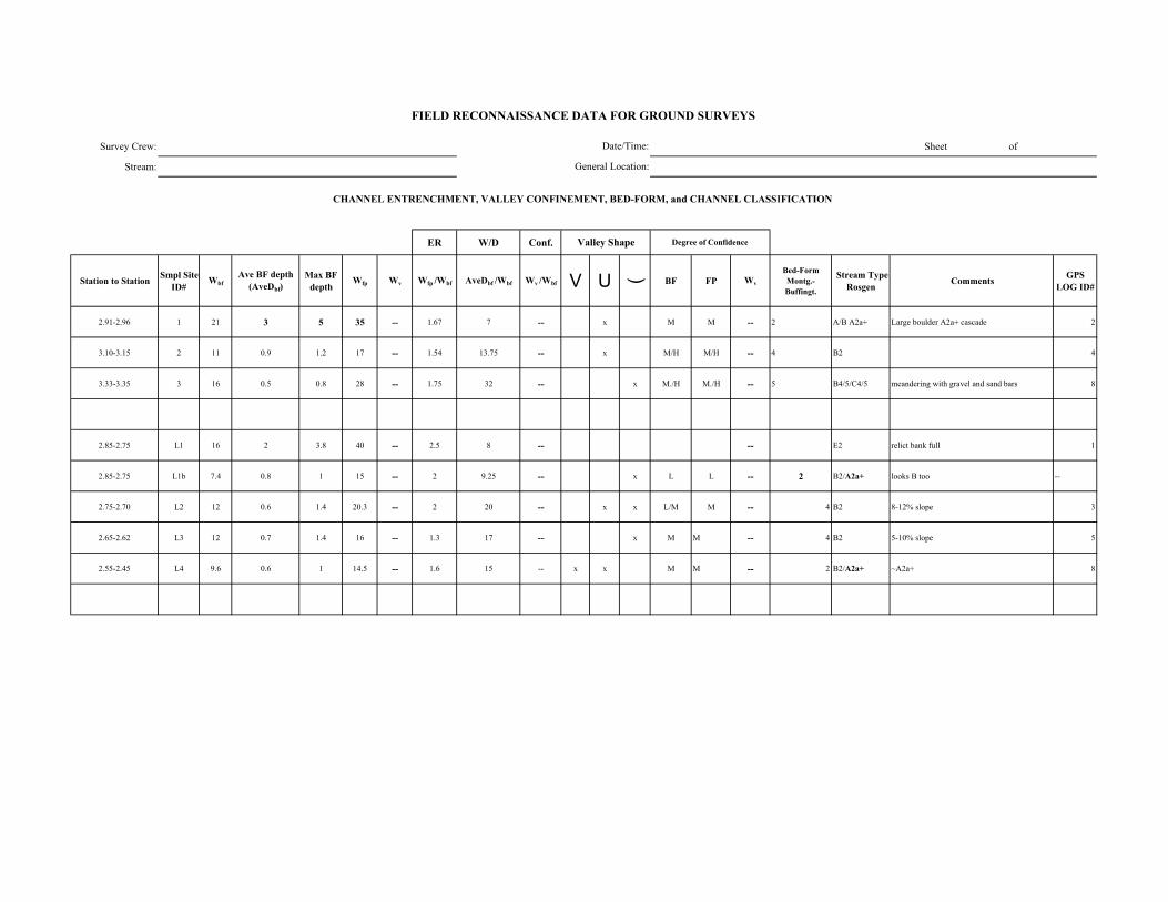
Survey Crew: Sheet of
Stream:
ER W/D Conf.
Station to Station Smpl Site ID#
WbfAve BF depth
(AveDbf)Max BF
depthWfp Wv Wfp /Wbf AveDbf /Wbf Wv /Wbf V U ( BF FP Wv
Bed-Form Montg.-Buffingt.
Stream Type Rosgen Comments GPS
LOG ID#
2.91-2.96 1 21 3 5 35 -- 1.67 7 -- x M M -- 2 A/B A2a+ Large boulder A2a+ cascade 2
3.10-3.15 2 11 0.9 1.2 17 -- 1.54 13.75 -- x M/H M/H -- 4 B2 4
3.33-3.35 3 16 0.5 0.8 28 -- 1.75 32 -- x M./H M./H -- 5 B4/5/C4/5 meandering with gravel and sand bars 8
2.85-2.75 L1 16 2 3.8 40 -- 2.5 8 -- -- E2 relict bank full 1
2.85-2.75 L1b 7.4 0.8 1 15 -- 2 9.25 -- x L L -- 2 B2/A2a+ looks B too --
2.75-2.70 L2 12 0.6 1.4 20.3 -- 2 20 -- x x L/M M -- 4 B2 8-12% slope 3
2.65-2.62 L3 12 0.7 1.4 16 -- 1.3 17 -- x M M -- 4 B2 5-10% slope 5
2.55-2.45 L4 9.6 0.6 1 14.5 -- 1.6 15 -- x x M M -- 2 B2/A2a+ ~A2a+ 8
FIELD RECONNAISSANCE DATA FOR GROUND SURVEYS
Degree of Confidence
CHANNEL ENTRENCHMENT, VALLEY CONFINEMENT, BED-FORM, and CHANNEL CLASSIFICATION
Valley Shape
Date/Time:
General Location:
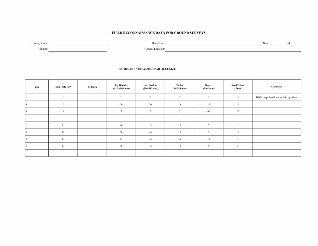
Date/Time:
General Location:
DOMINANT STREAMBED PARTICLE SIZE
gps Smpl Site ID# Bedrock Lg. Boulder (512-4096 mm)
Sm. Boulder (256-512 mm)
Cobble (64-256 mm)
Gravel (2-64 mm)
Sand/ Fines (<2mm)
2 1 75 5 5 5 10
4 2 50 20 10 10 10
8 3 5 5 5 60 25
1 L1 60 15 15 5 5
3 L2 30 40 15 5 10
5 L3 25 40 20 10 5
8 L4 70 10 10 5 5
FIELD RECONNAISSANCE DATA FOR GROUND SURVEYS
Sheet of
Comments
100% Large boulder underlain by others
Survey Crew:
Stream:
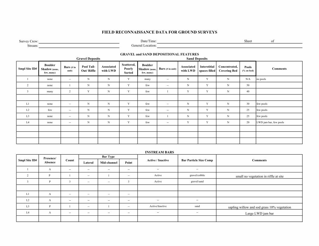
Survey Crew:Stream:
Smpl Site ID# Boulder
Shadow (none, few, many)
Bars (# in unit)
Pool Tail-Out/ Riffle
Associated with LWD
Scattered, Poorly Sorted
Boulder Shadow (none,
few, many)Bars (# in unit)
Associated with LWD
Interstitial spaces filled
Concentrated, Covering Bed
Pools (% on bed)
Comments
1 none -- N N Y many -- N Y N N/A no pools
2 none 1 N N Y few -- N Y N 50
3 many 2 Y N Y few 1 Y Y N 40
L1 none -- N N Y few -- N Y N 30 few pools
L2 few -- N N Y few -- N Y N 25 few pools
L3 none -- N N Y few 1 N Y N 25 few pools
L4 none -- N N Y few -- Y Y N 20 LWD jam bar, few pools
Lateral Mid-channel Point
1 A -- -- -- --
2 P 1 -- 1 --
3 P 3 -- -- 3
L1 A -- -- -- --
L2 A -- -- -- --
L3 P 1 -- 1 --
L4 A -- -- -- --
Comments
Sand Deposits
INSTREAM BARS
Presence/ Absence Count Active / Inactive Bar Particle Size Comp
Bar Type
sapling willow and sod grass 10% vegetation
Large LWD jam bar
FIELD RECONNAISSANCE DATA FOR GROUND SURVEYS
Date/Time:General Location:
Sheet of
GRAVEL and SAND DEPOSITIONAL FEATURESGravel Deposits
Smpl Site ID#
small no vegetation in riffle at site
--
--
gravel/cobble
gravel/sand
--
sand
--
Active/Inactive
--
--
Active
Active

Survey Crew: Date/Time: Sheet of
Stream: General Location:
Vegetation in Bankfull Channel
POSTION TYPE SIZE CLASS
1 A n/a
2 A n/a
3 P 1/2/3 5 1 2/3 n/a
L1 P 1/2 5 1 2/3 2
L2 P 1 5 1 2/3 2
L3 P 1/3 5/3 2 3 (2) 2
L4 P 1 5 1 2(1) ? (2)
Comments
VEGETATION ENCROACHMENT
FIELD RECONNAISSANCE DATA FOR GROUND SURVEYS
Smpl Site ID# VEG w/in BF
channel (P/A)
Vegetation Encroachment Rating
Veg Sz. Cl. in Relict BF Ch.
alder at bank full
few grasses and seedling willow at bank full
grass on large bars and in bed
alder in relict bank full, grass on banks and sand in bed
alder in relict bank full, grass on banks and sand in bed
alder in relict bank full, grass on banks and sand in bed
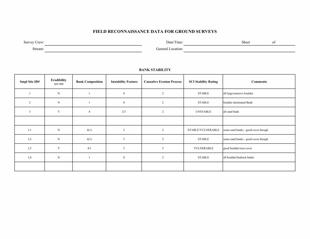
Survey Crew: Date/Time: Sheet of
Stream: General Location:
Smpl Site ID# Erodibility (yes /no)
Bank Composition Instability Feature Causative Erosion Process SCI Stability Rating Comments
1 N 1 0 2 STABLE all large/massive boulder
2 N 1 0 2 STABLE boulder dominated Bank
3 Y 4 2/3 2 UNSTABLE all sand bank
L1 N 4(1) 3 2 STABLE/VULNERABLE some sand banks - good cover though
L2 N 4(1) 3 2 STABLE some sand banks - good cover though
L3 Y 4/1 3 2 VULNERABLE good boulder/root cover
L4 N 1 0 2 STABLE all boulder/bedrock banks
FIELD RECONNAISSANCE DATA FOR GROUND SURVEYS
BANK STABILITY
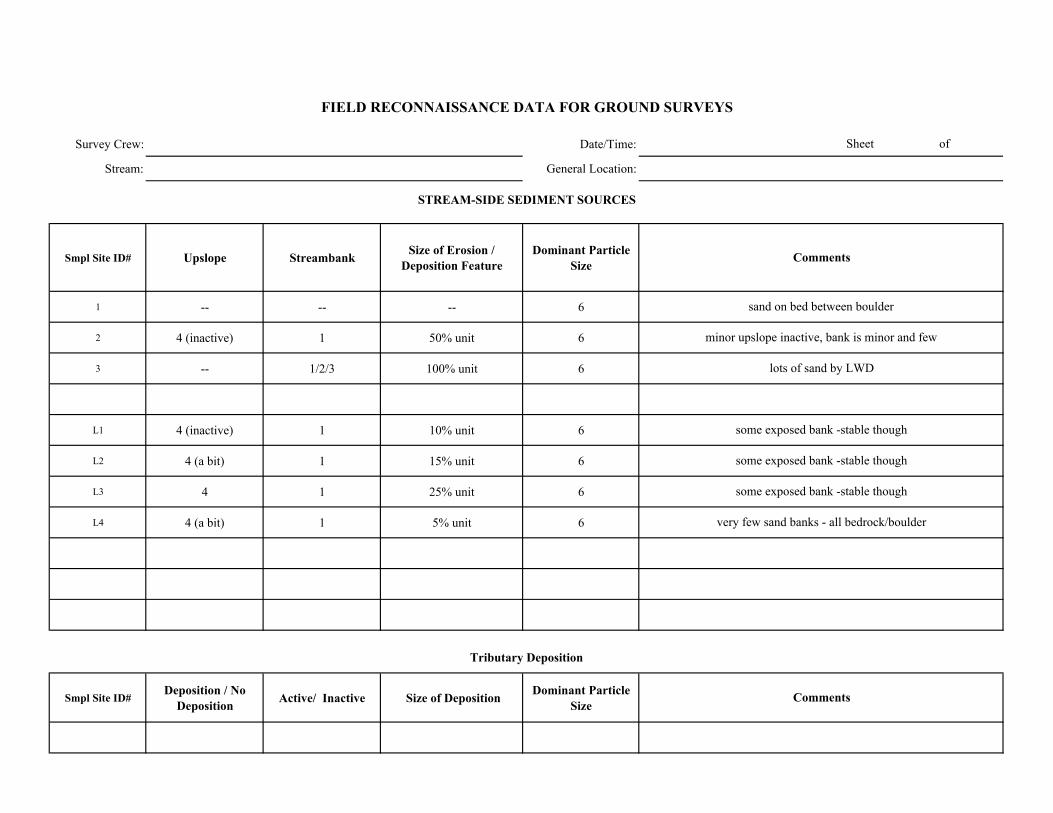
Survey Crew: Date/Time:
Stream: General Location:
Smpl Site ID# Upslope Streambank Size of Erosion / Deposition Feature
Dominant Particle Size
1 -- -- -- 6
2 4 (inactive) 1 50% unit 6
3 -- 1/2/3 100% unit 6
L1 4 (inactive) 1 10% unit 6
L2 4 (a bit) 1 15% unit 6
L3 4 1 25% unit 6
L4 4 (a bit) 1 5% unit 6
Smpl Site ID# Deposition / No
Deposition Active/ Inactive Size of Deposition Dominant Particle Size
Sheet of
FIELD RECONNAISSANCE DATA FOR GROUND SURVEYS
Comments
Tributary Deposition
STREAM-SIDE SEDIMENT SOURCES
Comments
sand on bed between boulder
minor upslope inactive, bank is minor and few
lots of sand by LWD
some exposed bank -stable though
some exposed bank -stable though
some exposed bank -stable though
very few sand banks - all bedrock/boulder
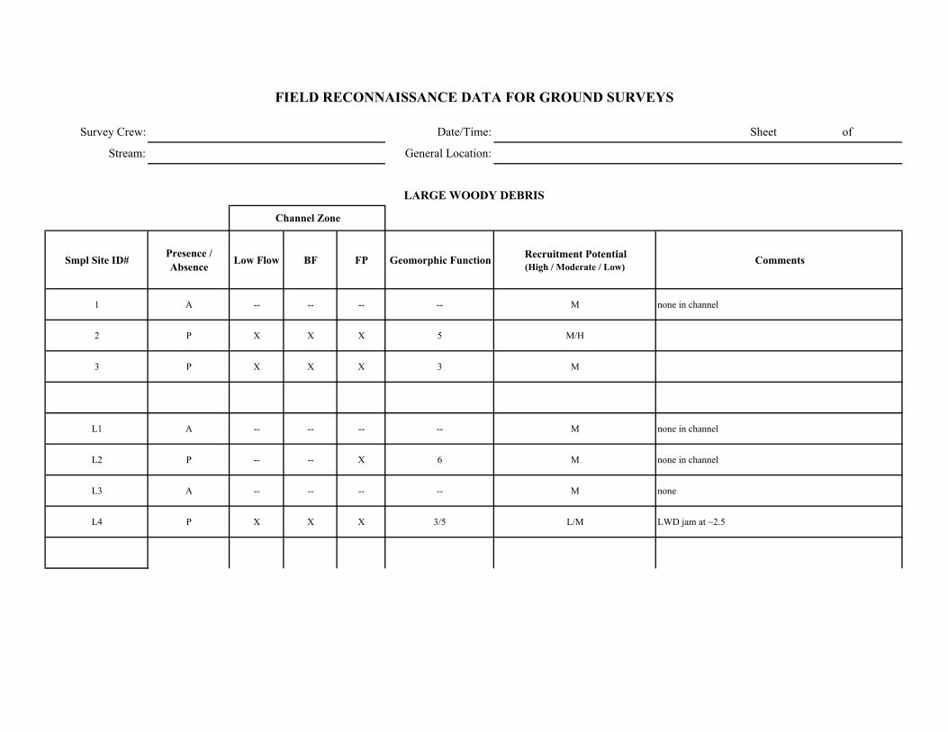
Survey Crew: Date/Time: Sheet of
Stream: General Location:
Smpl Site ID# Presence / Absence Low Flow BF FP Geomorphic Function Recruitment Potential
(High / Moderate / Low)Comments
1 A -- -- -- -- M none in channel
2 P X X X 5 M/H
3 P X X X 3 M
L1 A -- -- -- -- M none in channel
L2 P -- -- X 6 M none in channel
L3 A -- -- -- -- M none
L4 P X X X 3/5 L/M LWD jam at ~2.5
FIELD RECONNAISSANCE DATA FOR GROUND SURVEYS
LARGE WOODY DEBRIS
Channel Zone
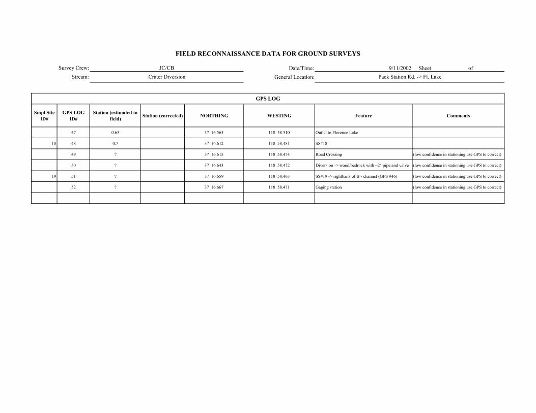
Date/Time: 9/11/2002 Sheet of General Location:
Smpl Site ID#
GPS LOG ID#
Station (estimated in field) Station (corrected) NORTHING WESTING Feature Comments
47 0.65 37 16.565 118 58.510 Outlet to Florence Lake
18 48 0.7 37 16.612 118 58.481 SS#18
49 ? 37 16.615 118 58.474 Road Crossing (low confidence in stationing use GPS to correct)
50 ? 37 16.643 118 58.472 Diversion -> wood/bedrock with ~2" pipe and valve (low confidence in stationing use GPS to correct)
19 51 ? 37 16.659 118 58.463 SS#19 -> rightbank of B - channel (GPS #46) (low confidence in stationing use GPS to correct)
52 ? 37 16.667 118 58.471 Gaging station (low confidence in stationing use GPS to correct)
FIELD RECONNAISSANCE DATA FOR GROUND SURVEYS
JC/CBCrater Diversion Pack Station Rd. -> Fl. Lake
GPS LOG
Survey Crew:Stream:
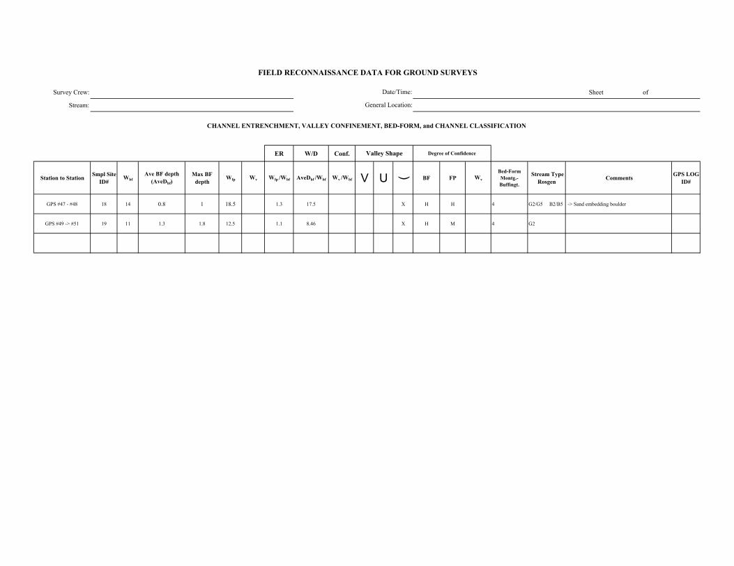
Survey Crew: Sheet of
Stream:
ER W/D Conf.
Station to Station Smpl Site ID#
WbfAve BF depth
(AveDbf)Max BF
depthWfp Wv Wfp /Wbf AveDbf /Wbf Wv /Wbf V U ( BF FP Wv
Bed-Form Montg.-Buffingt.
Stream Type Rosgen Comments GPS LOG
ID#
GPS #47 - #48 18 14 0.8 1 18.5 1.3 17.5 X H H 4 G2/G5 B2/B5 -> Sand embedding boulder
GPS #49 -> #51 19 11 1.3 1.8 12.5 1.1 8.46 X H M 4 G2
FIELD RECONNAISSANCE DATA FOR GROUND SURVEYS
Degree of Confidence
CHANNEL ENTRENCHMENT, VALLEY CONFINEMENT, BED-FORM, and CHANNEL CLASSIFICATION
Valley Shape
Date/Time:
General Location:

Date/Time:
General Location:
DOMINANT STREAMBED PARTICLE SIZE
gps Smpl Site ID# Bedrock Lg. Boulder (512-4096 mm)
Sm. Boulder (256-512 mm)
Cobble (64-256 mm)
Gravel (2-64 mm)
Sand/ Fines (<2mm)
18 10 15 20 15 15 25
19 1 25 25 15 10 10
Survey Crew:
Stream:
FIELD RECONNAISSANCE DATA FOR GROUND SURVEYS
Sheet of
Comments

Survey Crew:Stream:
Smpl Site ID# Boulder
Shadow (none, few, many)
Bars (# in unit)
Pool Tail-Out/ Riffle
Associated with LWD
Scattered, Poorly Sorted
Boulder Shadow (none, few, many)
Bars (# in unit)Associated with LWD
Interstitial spaces filled
Concentrated, Covering Bed
Pools (% on bed)
Comments
18 none - - X X none 2 X X in areas None sand embedding boulder
19 few - - - X few - X X - None
Lateral Mid-channel Point
18 P 2 - 2 -
19 A - - - -
inactive
-
Sand
-
Size 30x10' and 20x6' -> dense vegetation
FIELD RECONNAISSANCE DATA FOR GROUND SURVEYS
Date/Time:General Location:
Sheet of
GRAVEL and SAND DEPOSITIONAL FEATURESGravel Deposits
Smpl Site ID# Comments
Sand Deposits
INSTREAM BARS
Presence/ Absence Count Active / Inactive Bar Particle Size Comp
Bar Type
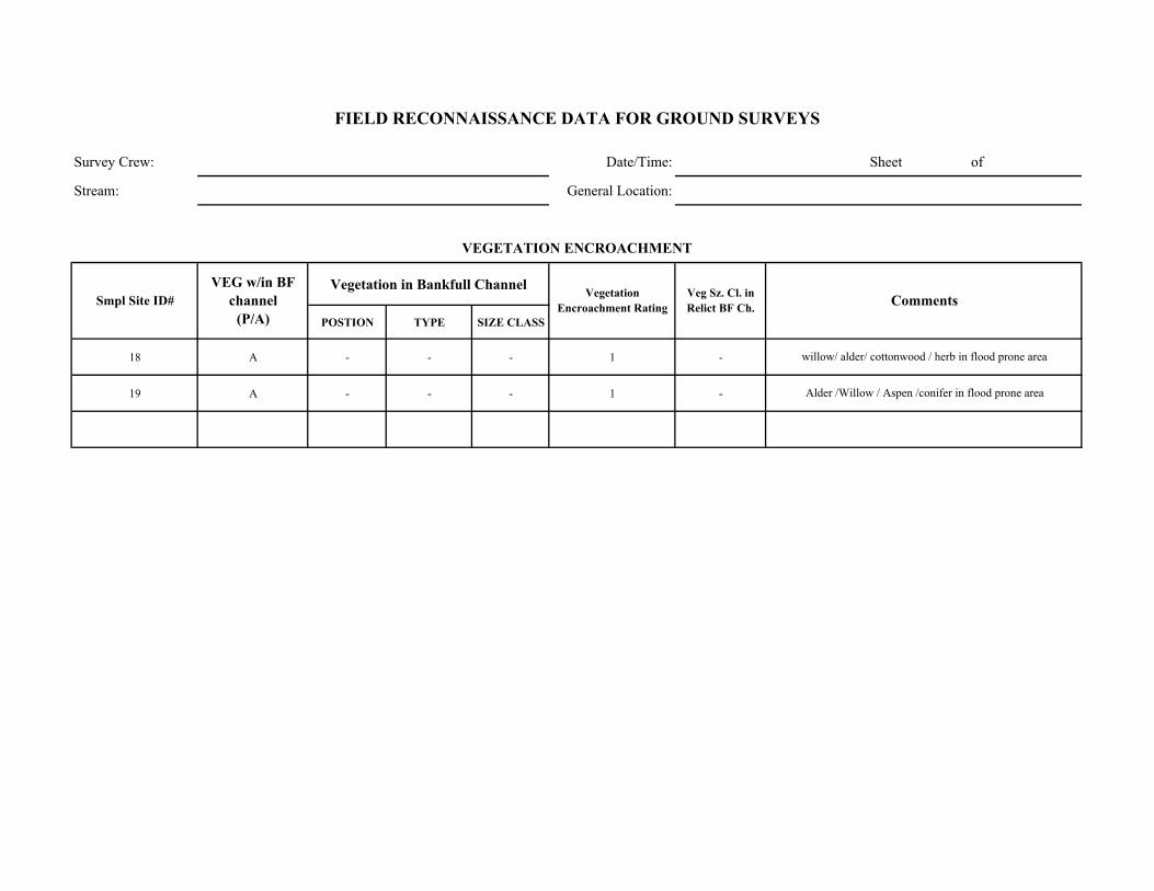
Survey Crew: Date/Time: Sheet of
Stream: General Location:
Vegetation in Bankfull Channel
POSTION TYPE SIZE CLASS
18 A - - - 1 -
19 A - - - 1 -
willow/ alder/ cottonwood / herb in flood prone area
Alder /Willow / Aspen /conifer in flood prone area
Comments
VEGETATION ENCROACHMENT
FIELD RECONNAISSANCE DATA FOR GROUND SURVEYS
Smpl Site ID# VEG w/in BF
channel (P/A)
Vegetation Encroachment Rating
Veg Sz. Cl. in Relict BF Ch.
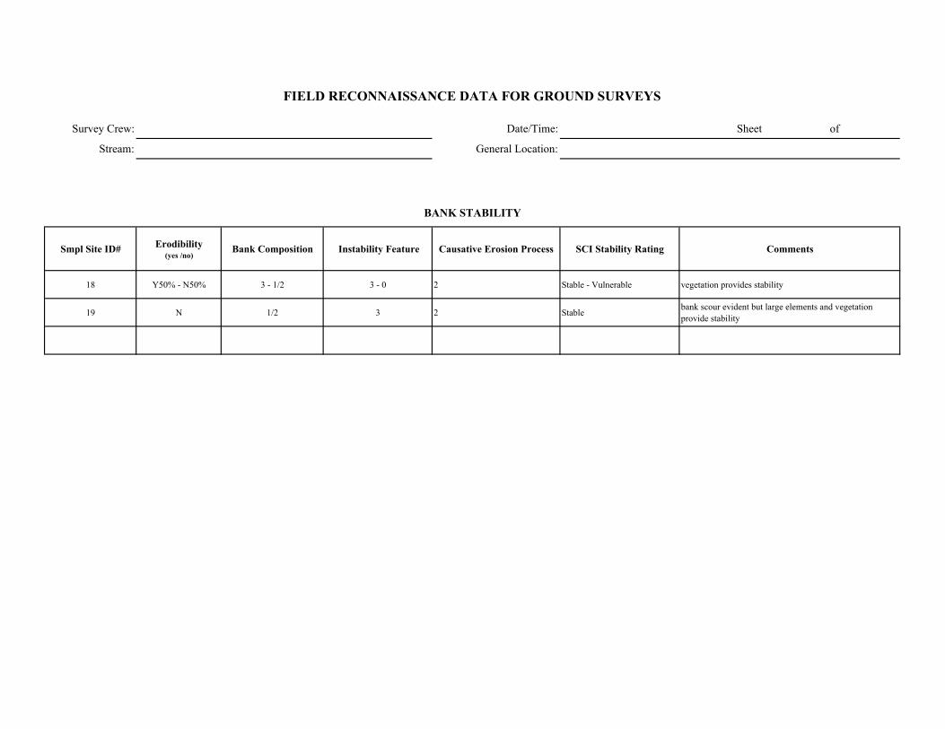
Survey Crew: Date/Time: Sheet of
Stream: General Location:
Smpl Site ID# Erodibility (yes /no)
Bank Composition Instability Feature Causative Erosion Process SCI Stability Rating Comments
18 Y50% - N50% 3 - 1/2 3 - 0 2 Stable - Vulnerable vegetation provides stability
19 N 1/2 3 2 Stable bank scour evident but large elements and vegetation provide stability
FIELD RECONNAISSANCE DATA FOR GROUND SURVEYS
BANK STABILITY

Survey Crew: Date/Time:
Stream: General Location:
Smpl Site ID# Upslope Streambank Size of Erosion / Deposition Feature
Dominant Particle Size
18 4 1 4 -> unit 1 -> 50% unit 6
19 4 1 unit 6
Smpl Site ID# Deposition / No
Deposition Active/ Inactive Size of Deposition Dominant Particle Size
Sheet of
FIELD RECONNAISSANCE DATA FOR GROUND SURVEYS
Comments
Tributary Deposition
STREAM-SIDE SEDIMENT SOURCES
Comments
~ 50% bank scour
-> bank scour evident, but large elements provide stability
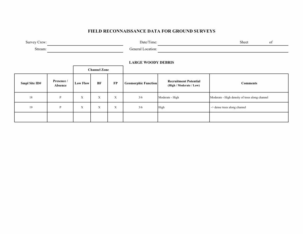
Survey Crew: Date/Time: Sheet of
Stream: General Location:
Smpl Site ID# Presence / Absence Low Flow BF FP Geomorphic Function Recruitment Potential
(High / Moderate / Low)Comments
18 P X X X 3/6 Moderate - High Moderate - High density of trees along channel
19 P X X X 3/6 High -> dense trees along channel
FIELD RECONNAISSANCE DATA FOR GROUND SURVEYS
LARGE WOODY DEBRIS
Channel Zone

Date/Time: 9/11/2002 Sheet of General Location:
Smpl Site ID# GPS LOG ID# Station (estimated in
field) Station (corrected) NORTHING WESTING Feature Comments
23 1.47 37 16.818 118 59.106 200' section downstream - left bank becomes better defined in A2a+ section then transitions back into sheet flow over bedrock A1a+
10 24 1.39 37 16.859 118 58.985 SS# 10 in A1a+
25 1.37 37 16.905 118 58.979 flow become more channnelized (vs. sheet flow upstream) in Bedrock
26 1.3 37 16.887 118 58.954 channel is dry - right bank from A1a+ to A/G - channel gradient decreases significantly as channel drops into valley floor
27 1.27 37 16.875 118 58.935 side channel / high flow channel joins main channel
11 28 1.25 37 16.878 118 58.913 SS # 11 - Pod. RB form A4 /A5 to Aa+ downstream
29 1.22 37 16.853 118 58.887 short G1/G2 section (150') within A2a+ reach as gradient decreases
30 1.19 37 16.862 118 58.864 Reach Break to A1a+/A2a+
12 31 1.14 37 16.853 118 58.809 SS #12 in A1a+ section
32 1.09 37 16.818 118 58.770
13 33 1.02 37 16.804 118 58.747 SS #3 in G1
34 0.98 37 16.789 118 58.744 Potential reach break from G1/G4/G5 to Aa+?
36 1 37 16.795 118 58.741 station 1.00 -1.09 - G1 station .98-1.02 - G4/G5
37 0.95 37 16.745 118 58.732 Reach Break from A1a+/A2a+ to A2/A5 - check dam/diversion in channel - concrete "dam" with 4" steel pipe along left bank.
38 0.92 37 16.755 118 58.700 Potential reach break from short A2/A5 - Aa+
14 39 0.88 37 16.767 118 58.655 SS#14 in Aa+ - near WP site E
40 0.86 37 16.765 118 58.642 RB form Aa+ to G2
15 41 0.8 37 16.748 118 58.569 SS# 15 in G2
42 0.76 37 16.734 118 58.545 Potential reach break from G2 - A1a+/A2a+
16 43 0.72 37 16.719 118 58.520 SS# 16 in A1a+/A2a+ ~200' upstream of road crossing
44 0.7 37 16.710 118 58.510 Florence lake road crossing - right bank from A2a+ - B2
17 45 0.66 37 16.694 118 58.498 SS #17 in B2
46 0.64 37 16.686 118 58.473 pack station road crossing
FIELD RECONNAISSANCE DATA FOR GROUND SURVEYS
JC/CBCrater Diversion Channel .64-1.5
Potential reach break from A1a+ to G1 (?) - gradient decreases
GPS LOG
Survey Crew:Stream:
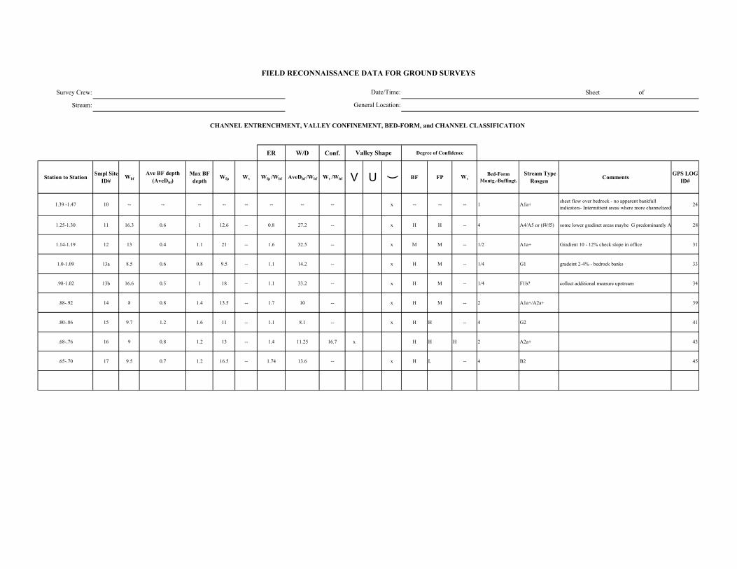
Survey Crew: Sheet of
Stream:
ER W/D Conf.
Station to Station Smpl Site ID#
WbfAve BF depth
(AveDbf)Max BF
depthWfp Wv Wfp /Wbf AveDbf /Wbf Wv /Wbf V U ( BF FP Wv
Bed-Form Montg.-Buffingt.
Stream Type Rosgen Comments GPS LOG
ID#
1.39 -1.47 10 -- -- -- -- -- -- -- -- x -- -- -- 1 A1a+ sheet flow over bedrock - no apparent bankfull indicators- Intermittent areas where more channelized 24
1.25-1.30 11 16.3 0.6 1 12.6 -- 0.8 27.2 -- x H H -- 4 A4/A5 or (f4/f5) some lower gradinet areas maybe G predominantly A 28
1.14-1.19 12 13 0.4 1.1 21 -- 1.6 32.5 -- x M M -- 1/2 A1a+ Gradient 10 - 12% check slope in office 31
1.0-1.09 13a 8.5 0.6 0.8 9.5 -- 1.1 14.2 -- x H M -- 1/4 G1 gradeint 2-4% - bedrock banks 33
.98-1.02 13b 16.6 0.5 1 18 -- 1.1 33.2 -- x H M -- 1/4 F1b? collect additional measure upstream 34
.88-.92 14 8 0.8 1.4 13.5 -- 1.7 10 -- x H M -- 2 A1a+/A2a+ 39
.80-.86 15 9.7 1.2 1.6 11 -- 1.1 8.1 -- x H H -- 4 G2 41
.68-.76 16 9 0.8 1.2 13 -- 1.4 11.25 16.7 x H H H 2 A2a+ 43
.65-.70 17 9.5 0.7 1.2 16.5 -- 1.74 13.6 -- x H L -- 4 B2 45
FIELD RECONNAISSANCE DATA FOR GROUND SURVEYS
Degree of Confidence
CHANNEL ENTRENCHMENT, VALLEY CONFINEMENT, BED-FORM, and CHANNEL CLASSIFICATION
Valley Shape
Date/Time:
General Location:
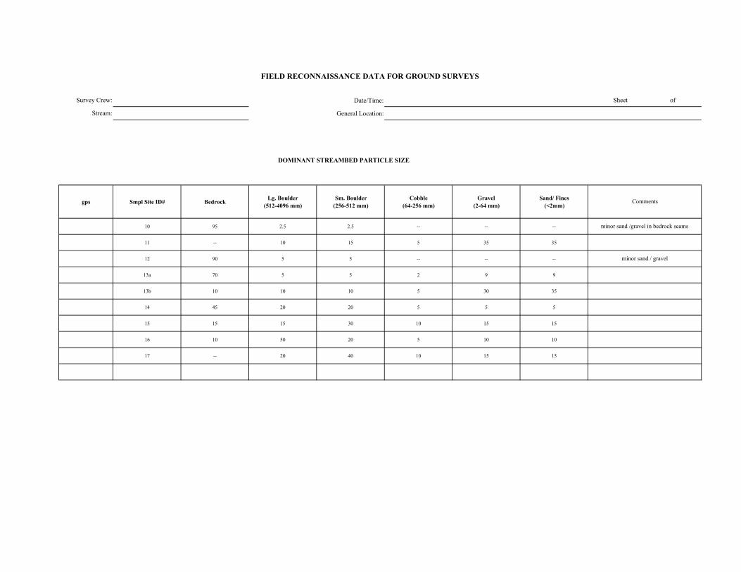
Date/Time:
General Location:
DOMINANT STREAMBED PARTICLE SIZE
gps Smpl Site ID# Bedrock Lg. Boulder (512-4096 mm)
Sm. Boulder (256-512 mm)
Cobble (64-256 mm)
Gravel (2-64 mm)
Sand/ Fines (<2mm)
10 95 2.5 2.5 -- -- --
11 -- 10 15 5 35 35
12 90 5 5 -- -- --
13a 70 5 5 2 9 9
13b 10 10 10 5 30 35
14 45 20 20 5 5 5
15 15 15 30 10 15 15
16 10 50 20 5 10 10
17 -- 20 40 10 15 15
Survey Crew:
Stream:
minor sand / gravel
FIELD RECONNAISSANCE DATA FOR GROUND SURVEYS
Sheet of
Comments
minor sand /gravel in bedrock seams
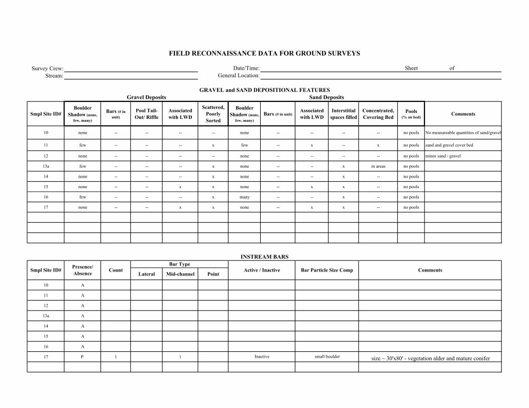
Survey Crew:Stream:
Smpl Site ID# Boulder
Shadow (none, few, many)
Bars (# in unit)
Pool Tail-Out/ Riffle
Associated with LWD
Scattered, Poorly Sorted
Boulder Shadow (none,
few, many)Bars (# in unit)
Associated with LWD
Interstitial spaces filled
Concentrated, Covering Bed
Pools (% on bed)
Comments
10 none -- -- -- -- none -- -- -- -- no pools No measureable quantities of sand/gravel
11 few -- -- -- x few -- x -- x no pools sand and gravel cover bed
12 none -- -- -- -- none -- -- -- -- no pools minor sand / gravel
13a few -- -- -- x none -- -- x in areas no pools
14 none -- -- -- x none -- -- x -- no pools
15 none -- -- x x none -- x x -- no pools
16 few -- -- -- x many -- -- x -- no pools
17 none -- -- x x none -- x x -- no pools
Lateral Mid-channel Point
10 A
11 A
12 A
13a A
14 A
15 A
16 A
17 P 1 1 Inactive small boulder size ~ 30'x80' - vegetation alder and mature conifer
FIELD RECONNAISSANCE DATA FOR GROUND SURVEYS
Date/Time:General Location:
Sheet of
GRAVEL and SAND DEPOSITIONAL FEATURESGravel Deposits
Smpl Site ID# Comments
Sand Deposits
INSTREAM BARS
Presence/ Absence Count Active / Inactive Bar Particle Size Comp
Bar Type
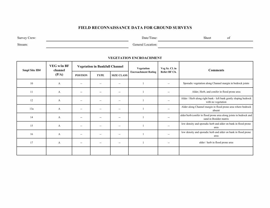
Survey Crew: Date/Time: Sheet of
Stream: General Location:
Vegetation in Bankfull Channel
POSTION TYPE SIZE CLASS
10 A -- -- -- 1 --
11 A -- -- -- 1 --
12 A -- -- -- 1 --
13a A -- -- -- 1 --
14 A -- -- -- 1 --
15 A -- -- -- 1 --
16 A -- -- -- 1 --
17 A -- -- -- 1 --
alder/herb/conifer in flood prone area along joints in bedrock and sand in Boulder matrix
low density and sporadic herb and alder on bank in flood prone area
low density and sporadic herb and alder on bank in flood prone area
alder / herb in flood prone area
Sporadic vegetation along Channel margin in bedrock joints
Alder, Herb, and conifer in flood prone area
Alder / Herb along right bank - left bank gently sloping bedrock with no vegetation
Alder along Channel margin in flood prone area where bedrock absent
Comments
VEGETATION ENCROACHMENT
FIELD RECONNAISSANCE DATA FOR GROUND SURVEYS
Smpl Site ID# VEG w/in BF
channel (P/A)
Vegetation Encroachment Rating
Veg Sz. Cl. in Relict BF Ch.
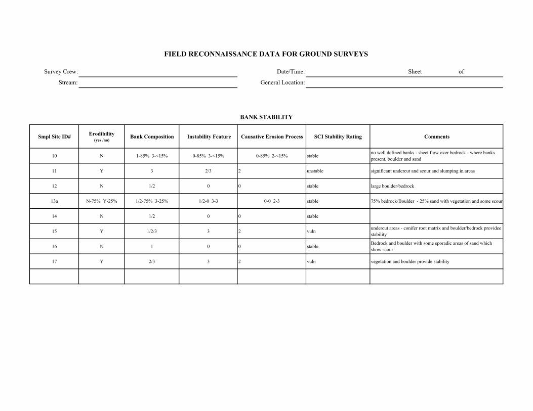
Survey Crew: Date/Time: Sheet of
Stream: General Location:
Smpl Site ID# Erodibility (yes /no)
Bank Composition Instability Feature Causative Erosion Process SCI Stability Rating Comments
10 N 1-85% 3-<15% 0-85% 3-<15% 0-85% 2-<15% stableno well defined banks - sheet flow over bedrock - where banks present, boulder and sand
11 Y 3 2/3 2 unstable significant undercut and scour and slumping in areas
12 N 1/2 0 0 stable large boulder/bedrock
13a N-75% Y-25% 1/2-75% 3-25% 1/2-0 3-3 0-0 2-3 stable 75% bedrock/Boulder - 25% sand with vegetation and some scour
14 N 1/2 0 0 stable
15 Y 1/2/3 3 2 vuln undercut areas - conifer root matrix and boulder/bedrock providee stability
16 N 1 0 0 stable Bedrock and boulder with some sporadic areas of sand which show scour
17 Y 2/3 3 2 vuln vegetation and boulder provide stability
FIELD RECONNAISSANCE DATA FOR GROUND SURVEYS
BANK STABILITY

Survey Crew: Date/Time:
Stream: General Location:
Smpl Site ID# Upslope Streambank Size of Erosion / Deposition Feature
Dominant Particle Size
10 4 1(<15%) upslope - unit bank - < 15% 6
11 4 1/2/3 unit 6
12
13a 4 unit 6
14 4 unit 6
15 4 2 unit 6
16 2/4 50% unit 2 -> 2/3 4 -> 6
17 1 70% unit 6
Smpl Site ID# Deposition / No
Deposition Active/ Inactive Size of Deposition Dominant Particle Size
Bank -> primarily sand with small boulder, cobble, and gravel
Rockfall along right bank - large and small boulder
surface scour
Sheet of
FIELD RECONNAISSANCE DATA FOR GROUND SURVEYS
Comments
Tributary Deposition
STREAM-SIDE SEDIMENT SOURCES
Comments
bank undercut and slumping
bedrock bed and banks
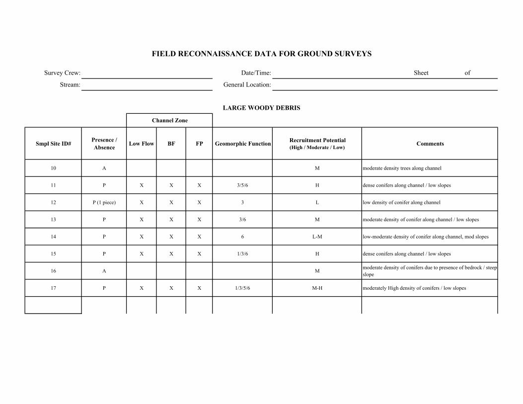
Survey Crew: Date/Time: Sheet of
Stream: General Location:
Smpl Site ID# Presence / Absence Low Flow BF FP Geomorphic Function Recruitment Potential
(High / Moderate / Low)Comments
10 A M moderate density trees along channel
11 P X X X 3/5/6 H dense conifers along channel / low slopes
12 P (1 piece) X X X 3 L low density of conifer along channel
13 P X X X 3/6 M moderate density of conifer along channel / low slopes
14 P X X X 6 L-M low-moderate density of conifer along channel, mod slopes
15 P X X X 1/3/6 H dense conifers along channel / low slopes
16 A M moderate density of conifers due to presence of bedrock / steep slope
17 P X X X 1/3/5/6 M-H moderately High density of conifers / low slopes
FIELD RECONNAISSANCE DATA FOR GROUND SURVEYS
LARGE WOODY DEBRIS
Channel Zone

Date/Time: 9/11/2002 sheet 2 of 10
General Location:
Smpl Site ID# GPS LOG ID# Station (estimated in
field) Station (corrected) NORTHING WESTING Feature Comments
1 2.18 37 16.600 118 59.677 Crater diversion
2 2.14 37 16.602 118 59.633 small drainage enters stream along leftbank
1 3 2.11 37 16.606 118 59.619 SS#1- potential right bank from A2-B2 as gradient decreases upstream >4%, downstream 3-5%
4 2.05 37 16.588 118 59.557 Gaging station with check dam. Gradient decreases upstream with sand deposits
2 5 2.07 37 16.584 118 59.556 SS#2 in G2
3 6 2.04 37 16.583 118 59.539 SS#3- 50' downstream of gage station - constructed wall absent, channel widens G3/G5
7 2 38 16.583 118 59.524 RB- Aa+?
4 8 1.94 37 16.593 118 59.457 SS#4 in Aa2a+
9 1.92 37 16.587 118 59.434 gradient decreases- right bank from A2a+ to C4/C5
10 1.9 No GPS coverage No GPS coverage
11 1.84 37 16.617 118 59.374 site channel with trickle of water. Dense alder channel width 6-8 ft., significant - LWD
5 12 1.84 37 16.622 118 59.409 SS#5 in Main Channel- C4/C5
13 1.8 37 16.627 118 59.377 gradient increases to B1/B2- start A1a+ (50') then gradient = 8%
14 1.7 37 16.716 118 59.303 Right bank from B1/B2 to A1/A5
6 15 1.75 37 16.640 118 59.341 SS#6 in B1/B2?
7 16 1.65 37 16.733 118 59.263 SS#7 in A1/A5
17 1.62 37 16.735 118 59.238 Potential Right bank A1/A5- Aa+
18 1.6 37 16.752 118 59.185 bend in channel to north and confluence with small drainage
8 19 1.58 37 16.754 118 59.185 SS#8 in A1a+/A2a+
20 1.57 37 16.777 118 59.173 No defined leftbank, bedrock channel, A1a+
21 1.53 37 16.789 118 59.154 Gradient increases, drops down hillslope
9 22 1.5 37 16.810 118 59.120 SS#9 in A1a+
depositional area, channel braids through cobble, gravel, sand
GPS LOG
Survey Crew:
Stream:
FIELD RECONNAISSANCE DATA FOR GROUND SURVEYS
JC/CB
Crater Diversion Stations 1.5-2.18

Survey Crew: JC/CB ####### sheet 3 of 10
Stream: Crater Diversion stations 1.5-2.18
ER W/D Conf.
Station to Station Smpl Site ID#
WbfAve BF depth
(AveDbf)Max BF
depthWfp Wv Wfp /Wbf AveDbf /Wbf Wv /Wbf V U ( BF FP Wv
Bed-Form Montg.-Buffingt.
Stream Type Rosgen Comments GPS LOG
ID#
2.11-2.18 1 5.5 1 1.2 6.5 1.2 5.5 X M M 3/4 A2Rightbank concrete/rock wall, leftbank placed and natural boulders, high gradient riffle 3
2.05-2.11 2 8.8 0.6 1 11.5 1.3 14.7 X M M 3/4 G2 (A2?)gradient approximately. 3-5%
5
2.0-2.05 3 13.5 0.7 0.9 17.5 1.3 19.3 X M M 4 B3/B5or G3/G5Downstream of gauging station, channel widens
6
1.94-2.0 4 16 1.3 1.7 23 1.4 9.4 X M M 2 A2a+ 8
1.84-1.90 5 10.6 0.4 0.7 25 2.4 26.5 X H L 4/6 C4/C5channel gradient decreases to <1%, braided with multiple side channels/ abandoned channels 12
1.70-1.80 6 15.5 1.2 1.7 21 1.4 12.9 X H M 4 B1/B2 (A1/A2?)Integrated slope =8-10%
15
1.60-1.70 7 6.5 0.8 1 6 0.92 8.1 X H H 4 A1/A5alternate areas of A1 and A5, gradient alternates between 8-12%
16
1.55-1.60 8 7.8 0.4 0.6 9 150 1.2 19.5 19.23 X H H 2 A1a+/ A2a+channel confined by bedrock
19
1.5-1.55 9 - - - - - - - - X - - 1 A1a+no apparent bankfull indicters, no well defined leftbank, sheet flow over bedrock 22
FIELD RECONNAISSANCE DATA FOR GROUND SURVEYS
Degree of Confidence
CHANNEL ENTRENCHMENT, VALLEY CONFINEMENT, BED-FORM, and CHANNEL CLASSIFICATION
Valley Shape
Date/Time:
General Location:
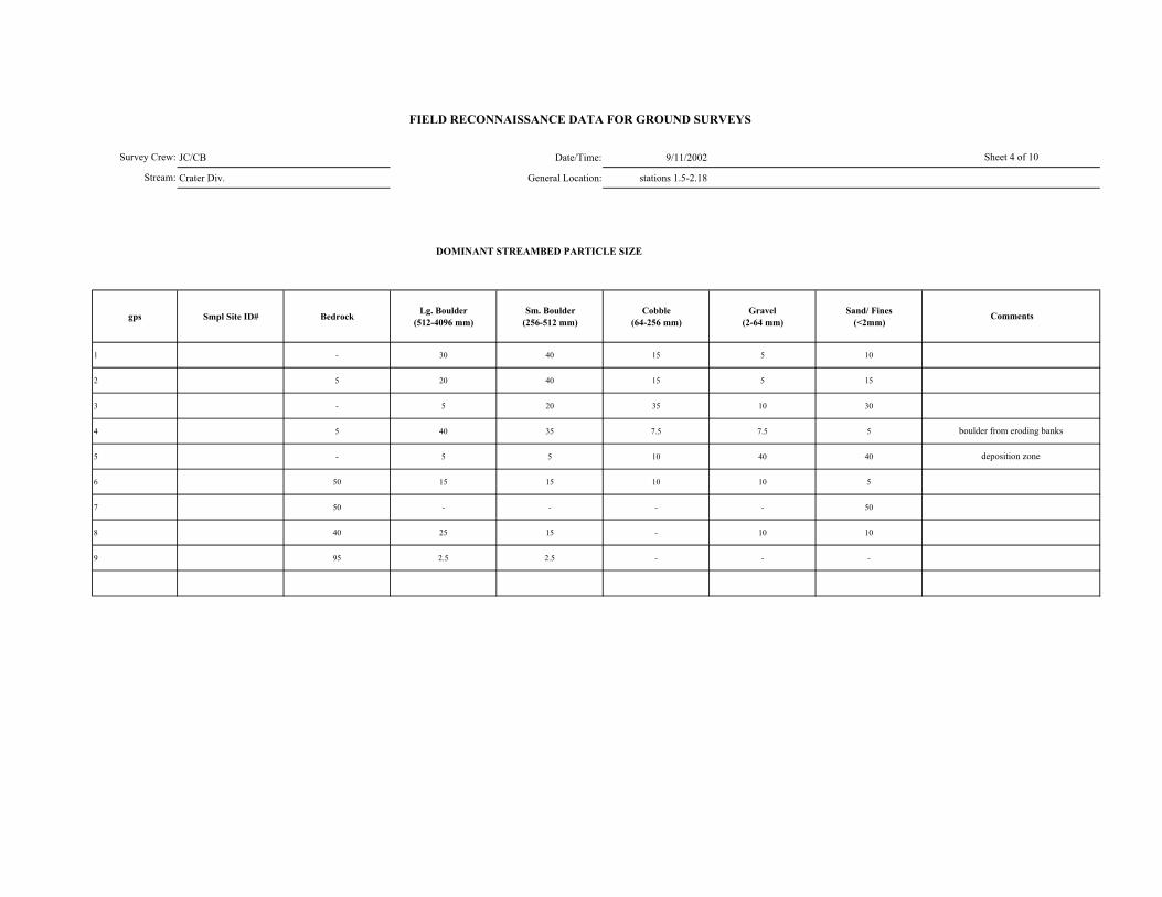
JC/CB Date/Time: 9/11/2002
Crater Div. General Location: stations 1.5-2.18
DOMINANT STREAMBED PARTICLE SIZE
gps Smpl Site ID# Bedrock Lg. Boulder (512-4096 mm)
Sm. Boulder (256-512 mm)
Cobble (64-256 mm)
Gravel (2-64 mm)
Sand/ Fines (<2mm)
1 - 30 40 15 5 10
2 5 20 40 15 5 15
3 - 5 20 35 10 30
4 5 40 35 7.5 7.5 5
5 - 5 5 10 40 40
6 50 15 15 10 10 5
7 50 - - - - 50
8 40 25 15 - 10 10
9 95 2.5 2.5 - - -
FIELD RECONNAISSANCE DATA FOR GROUND SURVEYS
Sheet 4 of 10
Comments
boulder from eroding banks
deposition zone
Survey Crew:
Stream:
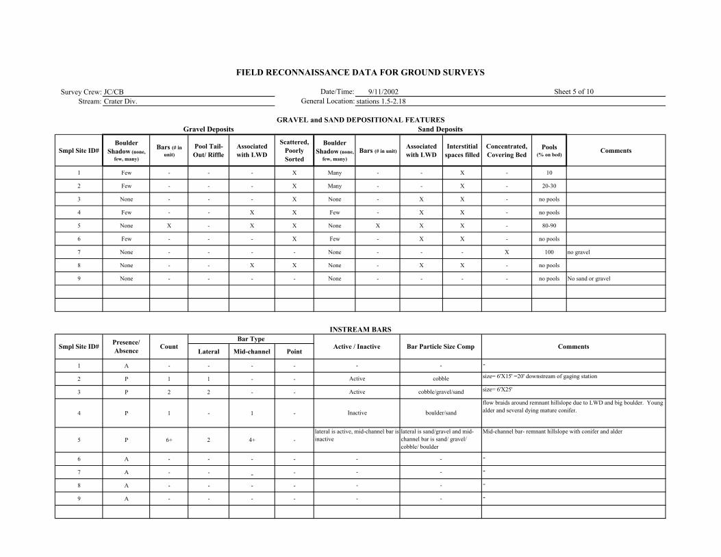
Survey Crew: JC/CB 9/11/2002Stream: Crater Div. stations 1.5-2.18
Smpl Site ID# Boulder
Shadow (none, few, many)
Bars (# in unit)
Pool Tail-Out/ Riffle
Associated with LWD
Scattered, Poorly Sorted
Boulder Shadow (none,
few, many)Bars (# in unit)
Associated with LWD
Interstitial spaces filled
Concentrated, Covering Bed
Pools (% on bed)
Comments
1 Few - - - X Many - - X - 10
2 Few - - - X Many - - X - 20-30
3 None - - - X None - X X - no pools
4 Few - - X X Few - X X - no pools
5 None X - X X None X X X - 80-90
6 Few - - - X Few - X X - no pools
7 None - - - - None - - - X 100 no gravel
8 None - - X X None - X X - no pools
9 None - - - - None - - - - no pools No sand or gravel
Lateral Mid-channel Point
1 A - - - -
2 P 1 1 - -
3 P 2 2 - -
4 P 1 - 1 -
5 P 6+ 2 4+ -
6 A - - - -
7 A - - - -
8 A - - - -
9 A - - - -
Comments
Sand Deposits
INSTREAM BARS
Presence/ Absence Count Active / Inactive Bar Particle Size Comp
Bar Type
-
-
-
FIELD RECONNAISSANCE DATA FOR GROUND SURVEYS
Date/Time:General Location:
Sheet 5 of 10
GRAVEL and SAND DEPOSITIONAL FEATURESGravel Deposits
Smpl Site ID#
-size= 6'X15' =20' downstream of gaging station
size= 6'X25'
flow braids around remnant hillslope due to LWD and big boulder. Young alder and several dying mature conifer.
-
Mid-channel bar- remnant hillslope with conifer and alder
-
--
-
cobble
cobble/gravel/sand
boulder/sand
lateral is sand/gravel and mid-channel bar is sand/ gravel/ cobble/ boulder
-
-
lateral is active, mid-channel bar is inactive
-
-
-
-
Active
Active
Inactive
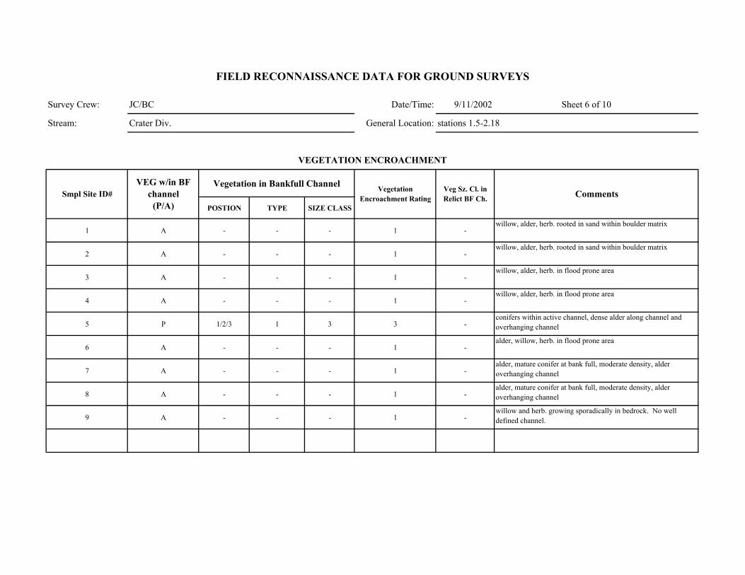
Survey Crew: JC/BC Date/Time: 9/11/2002 Sheet 6 of 10
Stream: Crater Div. General Location: stations 1.5-2.18
Vegetation in Bankfull Channel
POSTION TYPE SIZE CLASS
1 A - - - 1 -
2 A - - - 1 -
3 A - - - 1 -
4 A - - - 1 -
5 P 1/2/3 1 3 3 -
6 A - - - 1 -
7 A - - - 1 -
8 A - - - 1 -
9 A - - - 1 -
Comments
VEGETATION ENCROACHMENT
FIELD RECONNAISSANCE DATA FOR GROUND SURVEYS
Smpl Site ID# VEG w/in BF
channel (P/A)
Vegetation Encroachment Rating
Veg Sz. Cl. in Relict BF Ch.
willow, alder, herb. rooted in sand within boulder matrix
willow, alder, herb. rooted in sand within boulder matrix
willow, alder, herb. in flood prone area
willow, alder, herb. in flood prone area
conifers within active channel, dense alder along channel and overhanging channel
alder, willow, herb. in flood prone area
alder, mature conifer at bank full, moderate density, alder overhanging channel
alder, mature conifer at bank full, moderate density, alder overhanging channel
willow and herb. growing sporadically in bedrock. No well defined channel.
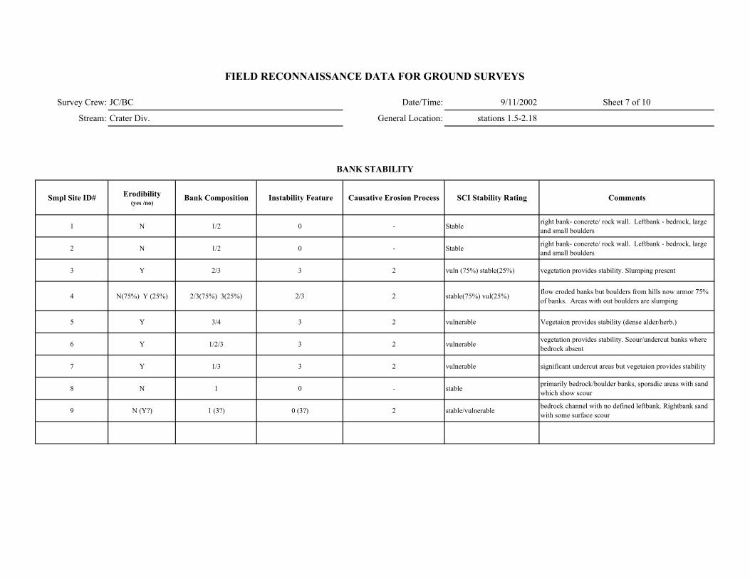
Survey Crew: JC/BC Date/Time: 9/11/2002 Sheet 7 of 10
Stream: Crater Div. General Location: stations 1.5-2.18
Smpl Site ID# Erodibility (yes /no)
Bank Composition Instability Feature Causative Erosion Process SCI Stability Rating Comments
1 N 1/2 0 - Stable right bank- concrete/ rock wall. Leftbank - bedrock, large and small boulders
2 N 1/2 0 - Stable right bank- concrete/ rock wall. Leftbank - bedrock, large and small boulders
3 Y 2/3 3 2 vuln (75%) stable(25%) vegetation provides stability. Slumping present
4 N(75%) Y (25%) 2/3(75%) 3(25%) 2/3 2 stable(75%) vul(25%) flow eroded banks but boulders from hills now armor 75% of banks. Areas with out boulders are slumping
5 Y 3/4 3 2 vulnerable Vegetaion provides stability (dense alder/herb.)
6 Y 1/2/3 3 2 vulnerable vegetation provides stability. Scour/undercut banks where bedrock absent
7 Y 1/3 3 2 vulnerable significant undercut areas but vegetaion provides stability
8 N 1 0 - stable primarily bedrock/boulder banks, sporadic areas with sand which show scour
9 N (Y?) 1 (3?) 0 (3?) 2 stable/vulnerable bedrock channel with no defined leftbank. Rightbank sand with some surface scour
FIELD RECONNAISSANCE DATA FOR GROUND SURVEYS
BANK STABILITY
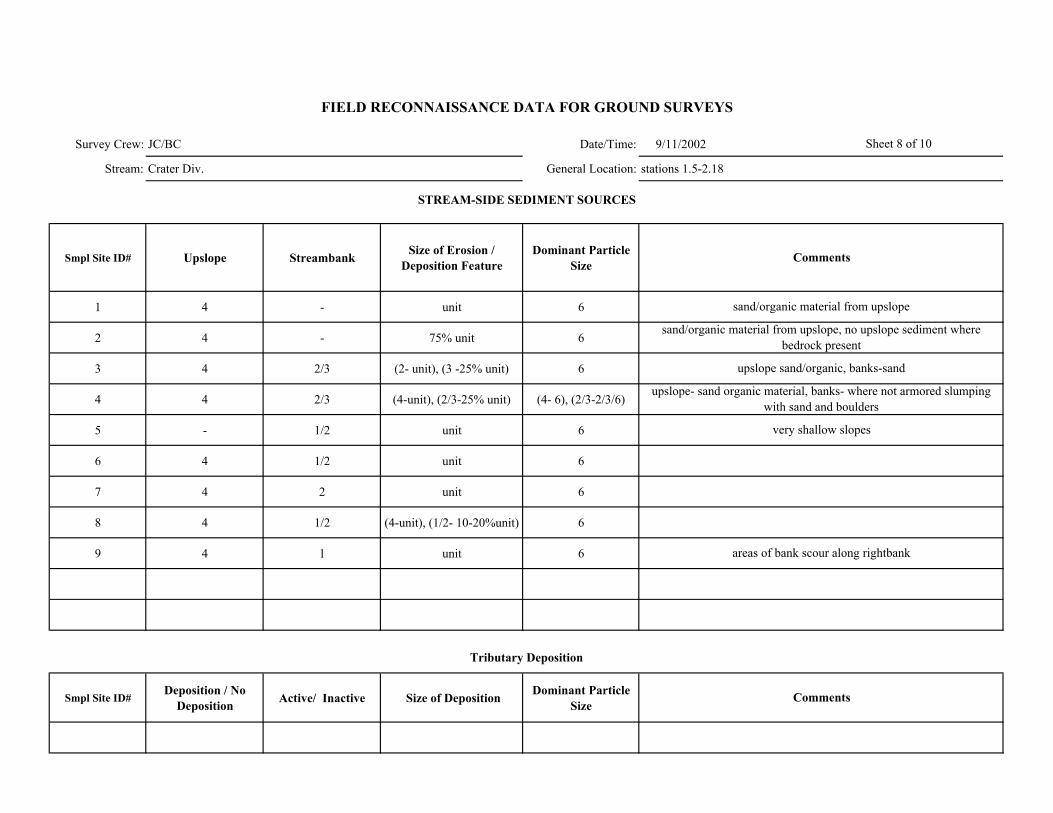
Survey Crew: JC/BC Date/Time: 9/11/2002
Stream: Crater Div. General Location: stations 1.5-2.18
Smpl Site ID# Upslope Streambank Size of Erosion / Deposition Feature
Dominant Particle Size
1 4 - unit 6
2 4 - 75% unit 6
3 4 2/3 (2- unit), (3 -25% unit) 6
4 4 2/3 (4-unit), (2/3-25% unit) (4- 6), (2/3-2/3/6)
5 - 1/2 unit 6
6 4 1/2 unit 6
7 4 2 unit 6
8 4 1/2 (4-unit), (1/2- 10-20%unit) 6
9 4 1 unit 6
Smpl Site ID# Deposition / No
Deposition Active/ Inactive Size of Deposition Dominant Particle Size
Sheet 8 of 10
FIELD RECONNAISSANCE DATA FOR GROUND SURVEYS
Comments
Tributary Deposition
STREAM-SIDE SEDIMENT SOURCES
Comments
sand/organic material from upslope
sand/organic material from upslope, no upslope sediment where bedrock present
upslope sand/organic, banks-sand
upslope- sand organic material, banks- where not armored slumping with sand and boulders
very shallow slopes
areas of bank scour along rightbank
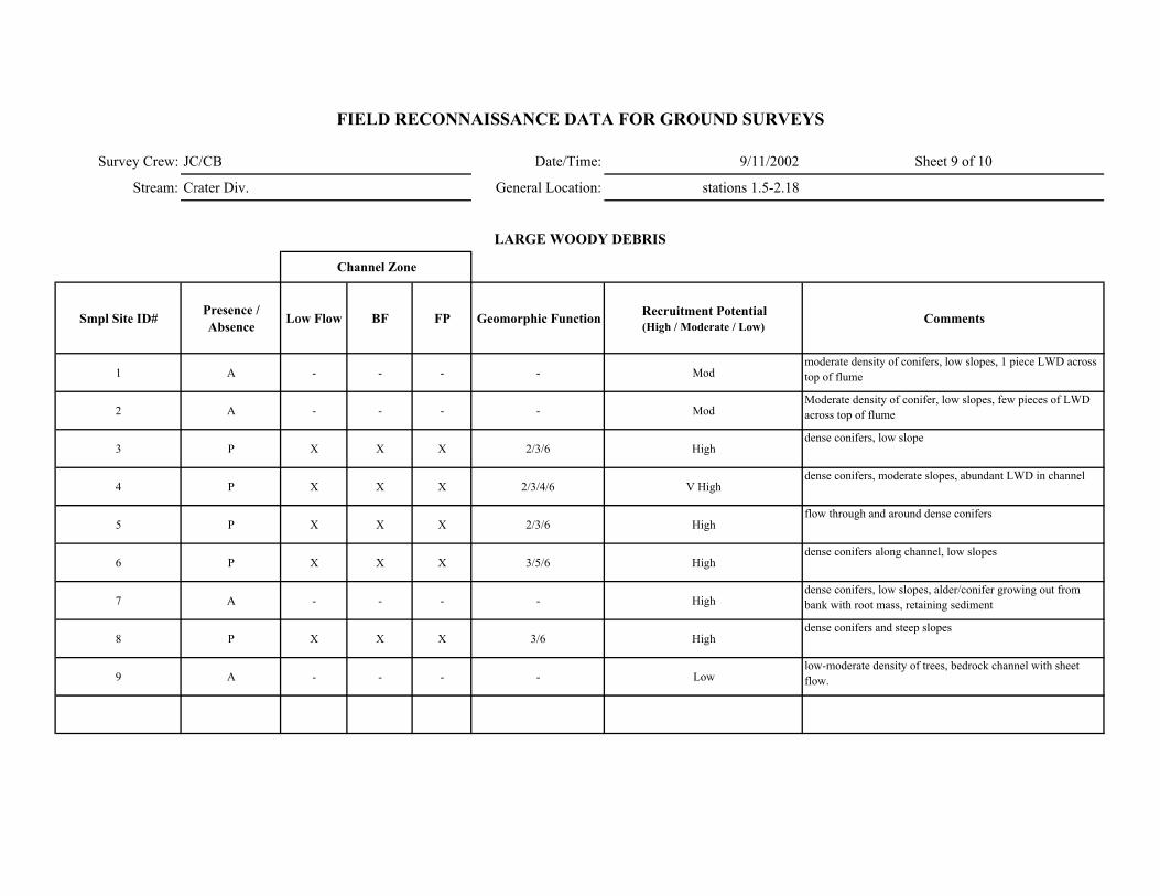
Survey Crew: JC/CB Date/Time: 9/11/2002 Sheet 9 of 10
Stream: Crater Div. General Location: stations 1.5-2.18
Smpl Site ID# Presence / Absence Low Flow BF FP Geomorphic Function Recruitment Potential
(High / Moderate / Low)Comments
1 A - - - - Modmoderate density of conifers, low slopes, 1 piece LWD across top of flume
2 A - - - - ModModerate density of conifer, low slopes, few pieces of LWD across top of flume
3 P X X X 2/3/6 Highdense conifers, low slope
4 P X X X 2/3/4/6 V Highdense conifers, moderate slopes, abundant LWD in channel
5 P X X X 2/3/6 Highflow through and around dense conifers
6 P X X X 3/5/6 Highdense conifers along channel, low slopes
7 A - - - - Highdense conifers, low slopes, alder/conifer growing out from bank with root mass, retaining sediment
8 P X X X 3/6 Highdense conifers and steep slopes
9 A - - - - Lowlow-moderate density of trees, bedrock channel with sheet flow.
FIELD RECONNAISSANCE DATA FOR GROUND SURVEYS
LARGE WOODY DEBRIS
Channel Zone
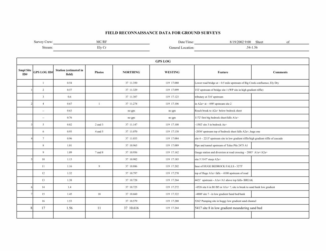
Date/Time: 8/19/2002 9:00 Sheet of
General Location:
Smpl Site ID# GPS LOG ID# Station (estimated in
field) Photos NORTHING WESTING Feature Comments
1 0.54 37 11.350 119 17.080 Lower road bridge at ~ 0.5 mile upstream of Big Creek confluence, Ely Dry
1 2 0.57 37 11.329 119 17.099 152' upstream of bridge site 1 (WP site in high gradient riffle)
3 0.6 37 11.307 119 17.123 tributary at 316' upstream
2 4 0.67 1 37 11.274 119 17.106 in A2a+ at ~ 690' upstream site 2
-- 0.63 no gps no gps Reach break to A2a+ below bedrock sheet
-- 0.76 no gps no gps 1172' first big bedrock sheet/falls A1a+
3 5 0.82 2 and 3 37 11.147 119 17.108 ~1502' site 3 in bedrock Aa+
6 0.93 4 and 5 37 11.070 119 17.138 ~2036' upstream top of bedrock sheet falls A2a+, huge one
4 7 0.96 37 11.033 119 17.084 site 4 ~ 2213' upstream site in low gradient riffle/high gradient riffle of cascade
8 1.01 37 10.965 119 17.089 Pipe and tunnel upstream of Talus Pile 2475 A1
9 1.09 7 and 8 37 10.956 119 17.162 Gauge station and diversion at road crossing ~ 2883' A1a+/A2a+
5 10 1.13 37 10.902 119 17.185 site 5 3147' steep A2a+
11 1.16 9 37 10.886 119 17.202 base of HUGE BEDROCK FALLS - 3275'
12 1.32 37 10.797 119 17.270 top of Huge A1a+ falls ~ 4100 upstream of road
13 1.38 37 10.728 119 17.264 4421' upstream - A1a+/A1 above top falls- BREAK
6 14 1.4 37 10.725 119 17.272 ~4526 site 6 in B1/B5 or A1a+ ?, site is break to sand bank low gradient
7 15 1.45 10 37 10.660 119 17.322 ~4800' site 7 - in low gradient Sand bed/bank
16 1.53 37 10.579 119 17.280 5262' Pumping site in boggy low gradient sand channel
8 17 1.56 11 37 10.616 119 17.264 5417 site 8 in low gradient meandering sand bed
GPS LOG
Survey Crew:
Stream:
FIELD RECONNAISSANCE DATA FOR GROUND SURVEYS
MC/RF
Ely Cr .54-1.56
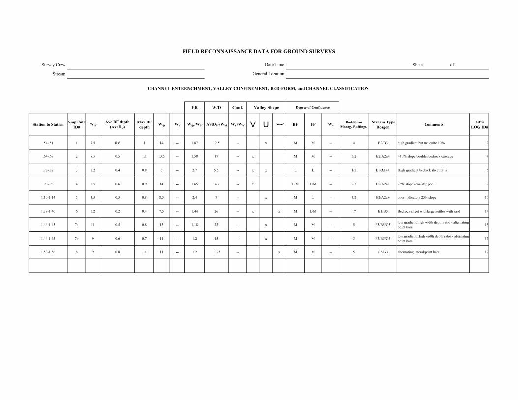
Survey Crew: Sheet of
Stream:
ER W/D Conf.
Station to Station Smpl Site ID#
WbfAve BF depth
(AveDbf)Max BF
depthWfp Wv Wfp /Wbf AveDbf /Wbf Wv /Wbf V U ( BF FP Wv
Bed-Form Montg.-Buffingt.
Stream Type Rosgen Comments GPS
LOG ID#
.54-.51 1 7.5 0.6 1 14 -- 1.87 12.5 -- x M M -- 4 B2/B3 high gradient but not quite 10% 2
.64-.68 2 8.5 0.5 1.1 13.5 -- 1.58 17 -- x M M -- 3/2 B2/A2a+ >10% slope boulder/bedrock cascade 4
.78-.82 3 2.2 0.4 0.8 6 -- 2.7 5.5 -- x x L L -- 1/2 E1/A1a+ High gradient bedrock sheet falls 5
.93-.96 4 8.5 0.6 0.9 14 -- 1.65 14.2 -- x L/M L/M -- 2/3 B2/A2a+ 25% slope -cas/step pool 7
1.10-1.14 5 3.5 0.5 0.8 8.5 -- 2.4 7 -- x M L -- 3/2 E2/A2a+ poor indicators 25% slope 10
1.38-1.40 6 5.2 0.2 0.4 7.5 -- 1.44 26 -- x x M L/M -- 1? B1/B5 Bedrock sheet with large kettles with sand 14
1.44-1.45 7a 11 0.5 0.8 13 -- 1.18 22 -- x M M -- 5 F5/B5/G5 low gradient/high width depth ratio - alternating point bars 15
1.44-1.45 7b 9 0.6 0.7 11 -- 1.2 15 -- x M M -- 5 F5/B5/G5 low gradient/High width depth ratio - alternatingpoint bars 15
1.53-1.56 8 9 0.8 1.1 11 -- 1.2 11.25 -- x M M -- 5 G5/G3 alternating lateral/point bars 17
FIELD RECONNAISSANCE DATA FOR GROUND SURVEYS
Degree of Confidence
CHANNEL ENTRENCHMENT, VALLEY CONFINEMENT, BED-FORM, and CHANNEL CLASSIFICATION
Valley Shape
Date/Time:
General Location:
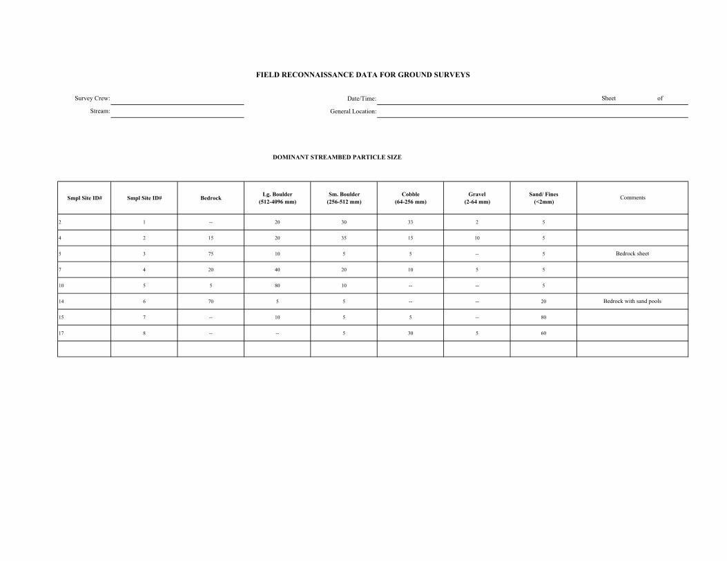
Date/Time:
General Location:
DOMINANT STREAMBED PARTICLE SIZE
Smpl Site ID# Smpl Site ID# Bedrock Lg. Boulder (512-4096 mm)
Sm. Boulder (256-512 mm)
Cobble (64-256 mm)
Gravel (2-64 mm)
Sand/ Fines (<2mm)
2 1 -- 20 30 33 2 5
4 2 15 20 35 15 10 5
5 3 75 10 5 5 -- 5
7 4 20 40 20 10 5 5
10 5 5 80 10 -- -- 5
14 6 70 5 5 -- -- 20
15 7 -- 10 5 5 -- 80
17 8 -- -- 5 30 5 60
Survey Crew:
Stream:
Bedrock with sand pools
Bedrock sheet
FIELD RECONNAISSANCE DATA FOR GROUND SURVEYS
Sheet of
Comments
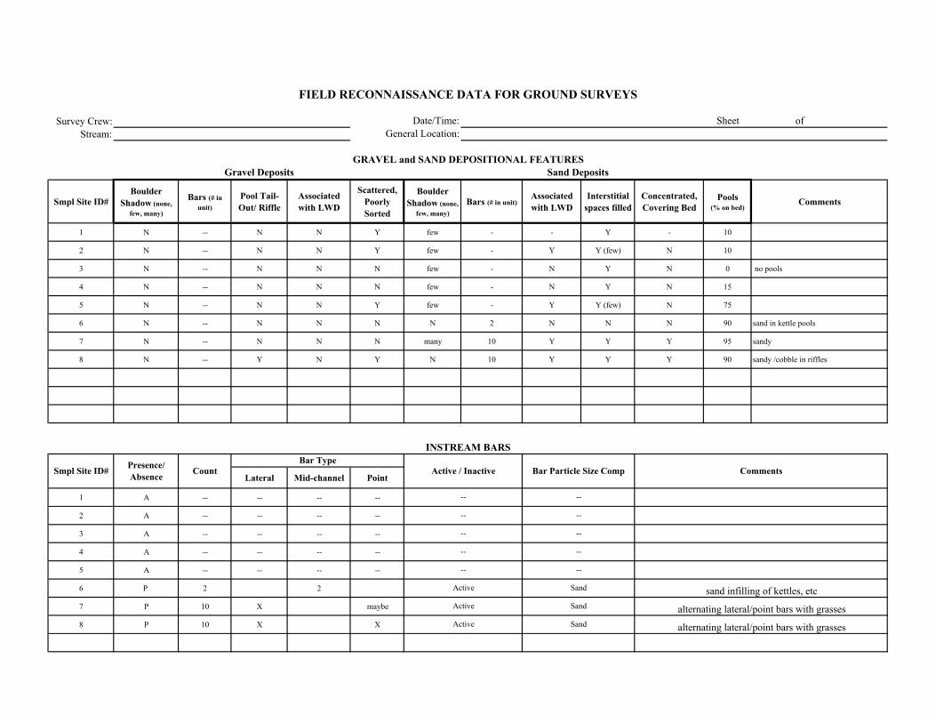
Survey Crew:Stream:
Smpl Site ID# Boulder
Shadow (none, few, many)
Bars (# in unit)
Pool Tail-Out/ Riffle
Associated with LWD
Scattered, Poorly Sorted
Boulder Shadow (none,
few, many)Bars (# in unit)
Associated with LWD
Interstitial spaces filled
Concentrated, Covering Bed
Pools (% on bed)
Comments
1 N -- N N Y few - - Y - 10
2 N -- N N Y few - Y Y (few) N 10
3 N -- N N N few - N Y N 0 no pools
4 N -- N N N few - N Y N 15
5 N -- N N Y few - Y Y (few) N 75
6 N -- N N N N 2 N N N 90 sand in kettle pools
7 N -- N N N many 10 Y Y Y 95 sandy
8 N -- Y N Y N 10 Y Y Y 90 sandy /cobble in riffles
Lateral Mid-channel Point
1 A -- -- -- --
2 A -- -- -- --
3 A -- -- -- --
4 A -- -- -- --
5 A -- -- -- --
6 P 2 2
7 P 10 X maybe
8 P 10 X X
--
--
--
--
--
Active
Active
Active
--
--
--
--
--
Sand
Sand
Sand
sand infilling of kettles, etc
alternating lateral/point bars with grasses
alternating lateral/point bars with grasses
FIELD RECONNAISSANCE DATA FOR GROUND SURVEYS
Date/Time:General Location:
Sheet of
GRAVEL and SAND DEPOSITIONAL FEATURESGravel Deposits
Smpl Site ID# Comments
Sand Deposits
INSTREAM BARS
Presence/ Absence Count Active / Inactive Bar Particle Size Comp
Bar Type
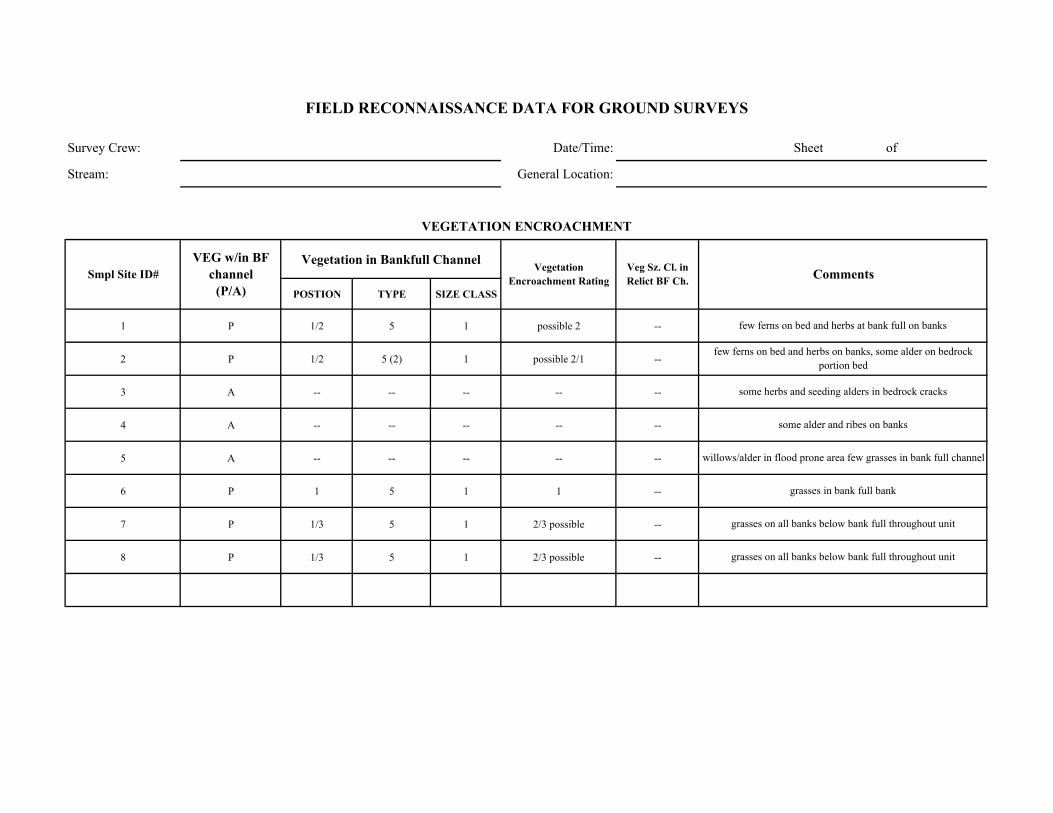
Survey Crew: Date/Time: Sheet of
Stream: General Location:
Vegetation in Bankfull Channel
POSTION TYPE SIZE CLASS
1 P 1/2 5 1 possible 2 --
2 P 1/2 5 (2) 1 possible 2/1 --
3 A -- -- -- -- --
4 A -- -- -- -- --
5 A -- -- -- -- --
6 P 1 5 1 1 --
7 P 1/3 5 1 2/3 possible --
8 P 1/3 5 1 2/3 possible --
willows/alder in flood prone area few grasses in bank full channel
grasses in bank full bank
grasses on all banks below bank full throughout unit
grasses on all banks below bank full throughout unit
few ferns on bed and herbs at bank full on banks
few ferns on bed and herbs on banks, some alder on bedrock portion bed
some herbs and seeding alders in bedrock cracks
some alder and ribes on banks
Comments
VEGETATION ENCROACHMENT
FIELD RECONNAISSANCE DATA FOR GROUND SURVEYS
Smpl Site ID# VEG w/in BF
channel (P/A)
Vegetation Encroachment Rating
Veg Sz. Cl. in Relict BF Ch.
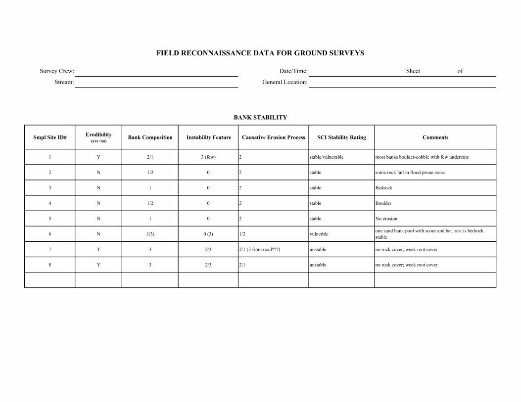
Survey Crew: Date/Time: Sheet of
Stream: General Location:
Smpl Site ID# Erodibility (yes /no)
Bank Composition Instability Feature Causative Erosion Process SCI Stability Rating Comments
1 Y 2/1 3 (few) 2 stable/vulnerable most banks boulder-cobble with few undercuts
2 N 1/2 0 2 stable some rock fall in flood prone areas
3 N 1 0 2 stable Bedrock
4 N 1/2 0 2 stable Boulder
5 N 1 0 2 stable No erosion
6 N 1(3) 0 (3) 1/2 vulnerble one sand bank pool with scour and bar, rest is bedrock stable
7 Y 3 2/3 2/1 (3 from road???) unstable no rock cover; weak root cover
8 Y 3 2/3 2/1 unstable no rock cover; weak root cover
FIELD RECONNAISSANCE DATA FOR GROUND SURVEYS
BANK STABILITY
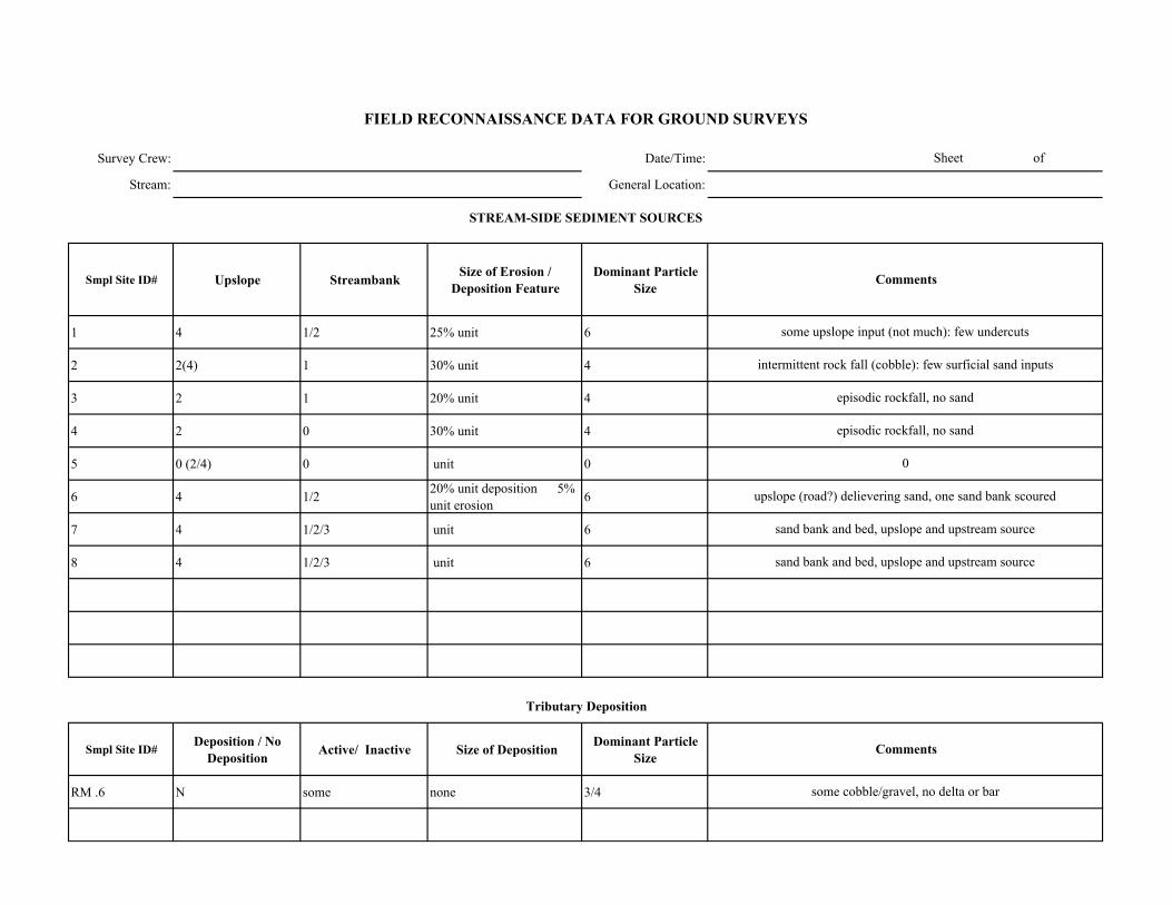
Survey Crew: Date/Time:
Stream: General Location:
Smpl Site ID# Upslope Streambank Size of Erosion / Deposition Feature
Dominant Particle Size
1 4 1/2 25% unit 6
2 2(4) 1 30% unit 4
3 2 1 20% unit 4
4 2 0 30% unit 4
5 0 (2/4) 0 unit 0
6 4 1/2 20% unit deposition 5% unit erosion 6
7 4 1/2/3 unit 6
8 4 1/2/3 unit 6
Smpl Site ID# Deposition / No Deposition Active/ Inactive Size of Deposition Dominant Particle
Size
RM .6 N some none 3/4 some cobble/gravel, no delta or bar
0
upslope (road?) delievering sand, one sand bank scoured
sand bank and bed, upslope and upstream source
sand bank and bed, upslope and upstream source
Sheet of
FIELD RECONNAISSANCE DATA FOR GROUND SURVEYS
Comments
Tributary Deposition
STREAM-SIDE SEDIMENT SOURCES
Comments
some upslope input (not much): few undercuts
intermittent rock fall (cobble): few surficial sand inputs
episodic rockfall, no sand
episodic rockfall, no sand
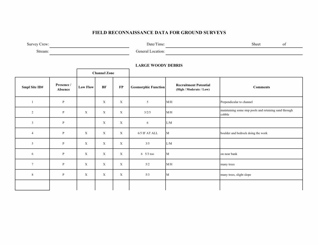
Survey Crew: Date/Time: Sheet of
Stream: General Location:
Smpl Site ID# Presence / Absence Low Flow BF FP Geomorphic Function Recruitment Potential
(High / Moderate / Low)Comments
1 P X X 5 M/H Perpendicular to channel
2 P X X X 3/2/5 M/H maintaining some step pools and retaining sand through cobble
3 P X X 6 L/M
4 P X X X 6/5 IF AT ALL M boulder and bedrock doing the work
5 P X X X 3/5 L/M
6 P X X X 6 5/3 too M on near bank
7 P X X X 5/2 M/H many trees
8 P X X X 5/3 M many trees, slight slope
FIELD RECONNAISSANCE DATA FOR GROUND SURVEYS
LARGE WOODY DEBRIS
Channel Zone
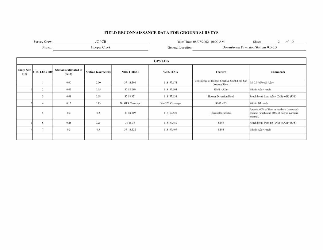
Date/Time: 08/07/2002 10:00 AM Sheet 2 of 10
General Location:
Smpl Site ID# GPS LOG ID# Station (estimated in
field) Station (corrected) NORTHING WESTING Feature Comments
1 0.00 0.00 37 18.306 118 57.674 Confluence of Hooper Creek & South Fork San Joaquin River
0.0-0.08 (Road) A2a+
1 2 0.05 0.05 37 18.289 118 57.604 SS #1 - A2a+ Within A2a+ reach
3 0.08 0.08 37 18.321 118 57.638 Hooper Diversion Road Reach break from A2a+ (D/S) to B3 (U/S)
2 4 0.13 0.13 No GPS Coverage No GPS Coverage SS#2 - B3 Within B3 reach
5 0.2 0.2 37 18.349 118 57.521 Channel bifurcates Approx. 60% of flow in southern (surveyed) channel (south) and 40% of flow in northern channel.
3 6 0.25 0.25 37 18.33 118 57.480 SS#3 Reach break from B3 (D/S) to A2a+ (U/S)
4 7 0.3 0.3 37 18.322 118 57.407 SS#4 Within A2a+ reach
GPS LOG
Survey Crew:
Stream:
FIELD RECONNAISSANCE DATA FOR GROUND SURVEYS
JC / CB
Hooper Creek Downstream Diversion Stations 0.0-0.3
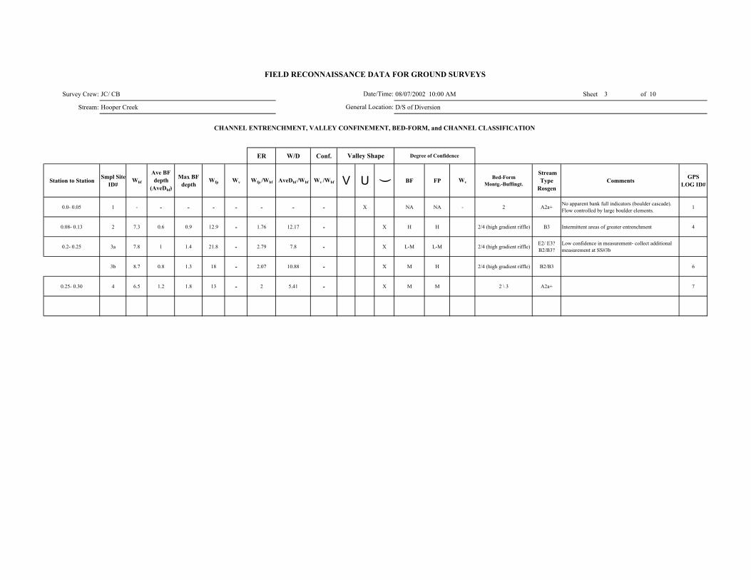
Survey Crew: JC/ CB 08/07/2002 10:00 AM Sheet 3 of 10
Stream: Hooper Creek D/S of Diversion
ER W/D Conf.
Station to Station Smpl Site ID#
Wbf
Ave BF depth
(AveDbf)
Max BF depth
Wfp Wv Wfp /Wbf AveDbf /Wbf Wv /Wbf V U ( BF FP WvBed-Form
Montg.-Buffingt.
Stream Type
RosgenComments GPS
LOG ID#
0.0- 0.05 1 - - - - - - - - X NA NA - 2 A2a+ No apparent bank full indicators (boulder cascade). Flow controlled by large boulder elements. 1
0.08- 0.13 2 7.3 0.6 0.9 12.9 - 1.76 12.17 - X H H 2/4 (high gradient riffle) B3 Intermittent areas of greater entrenchment 4
0.2- 0.25 3a 7.8 1 1.4 21.8 - 2.79 7.8 - X L-M L-M 2/4 (high gradient riffle) E2/ E3? B2/B3?
Low confidence in measurement- collect additional measurement at SS#3b
3b 8.7 0.8 1.3 18 - 2.07 10.88 - X M H 2/4 (high gradient riffle) B2/B3 6
0.25- 0.30 4 6.5 1.2 1.8 13 - 2 5.41 - X M M 2 \ 3 A2a+ 7
FIELD RECONNAISSANCE DATA FOR GROUND SURVEYS
Degree of Confidence
CHANNEL ENTRENCHMENT, VALLEY CONFINEMENT, BED-FORM, and CHANNEL CLASSIFICATION
Valley Shape
Date/Time:
General Location:
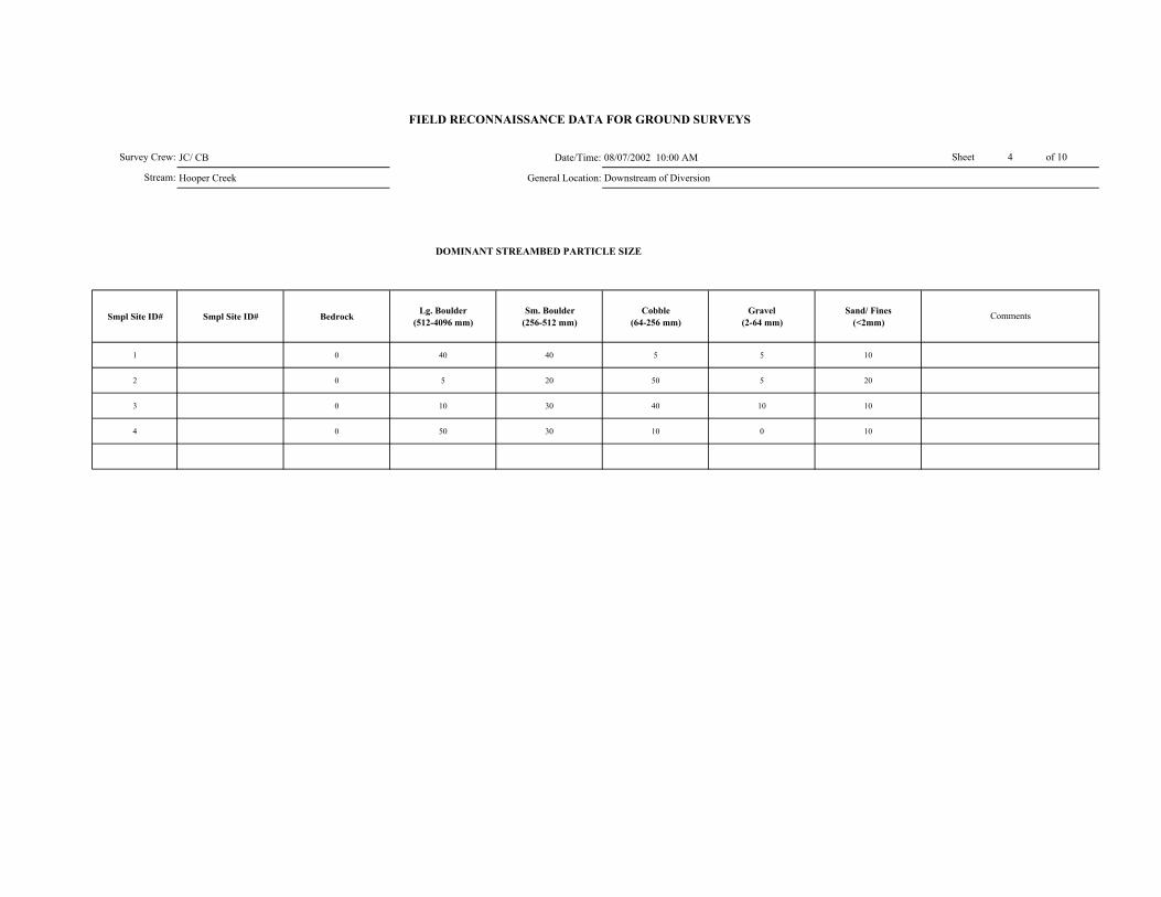
JC/ CB Date/Time: 08/07/2002 10:00 AM
Hooper Creek General Location: Downstream of Diversion
DOMINANT STREAMBED PARTICLE SIZE
Smpl Site ID# Smpl Site ID# Bedrock Lg. Boulder (512-4096 mm)
Sm. Boulder (256-512 mm)
Cobble (64-256 mm)
Gravel (2-64 mm)
Sand/ Fines (<2mm)
1 0 40 40 5 5 10
2 0 5 20 50 5 20
3 0 10 30 40 10 10
4 0 50 30 10 0 10
Sheet 4 of 10
Stream:
Survey Crew:
FIELD RECONNAISSANCE DATA FOR GROUND SURVEYS
Comments
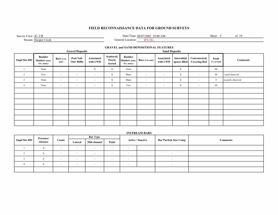
Survey Crew: JC/ CB 08/07/2002 10:00 AMStream: Hooper Creek D\S Div.
Smpl Site ID# Boulder
Shadow (none, few, many)
Bars (# in unit)
Pool Tail-Out/ Riffle
Associated with LWD
Scattered, Poorly Sorted
Boulder Shadow (none,
few, many)Bars (# in unit)
Associated with LWD
Interstitial spaces filled
Concentrated, Covering Bed
Pools (% on bed)
Comments
1 None - - X X None - - X - 80
2 Few - - - X Many - - X - 80 1 pool observed
3 None - - - X Many - - X - 0 no pools observed
4 None - - - X Few - - X - 40
Lateral Mid-channel Point
1 A - - - - -
2 A - - - - -
3 A - - - - -
4 A - - - - -
-
-
-
-
FIELD RECONNAISSANCE DATA FOR GROUND SURVEYS
Date/Time:General Location:
Sheet 5 of 10
GRAVEL and SAND DEPOSITIONAL FEATURESGravel Deposits
Smpl Site ID# Comments
Sand Deposits
INSTREAM BARS
Presence/ Absence Count Active / Inactive Bar Particle Size Comp
Bar Type

Survey Crew: JC\ CB Date/Time: 08/07/2002 10:00 AM Sheet 6 of 10
Stream: Hooper Cr. General Location:ream diversion
Vegetation in Bankfull Channel
POSTION TYPE SIZE CLASS
1 P 1 / 2 1 /2 / 5 1 /2 / 3 2 -
2 A - - - 1 -
3 A - - - 1 -
4 A - - - 1 -
Alders/ herb. vegetation along channel margins in flood prone area
Alders/ herb. vegetation along channel margins in flood prone area
Alders/ herb. vegetation along channel margins in flood prone area
Difficult to discern bank full channel due to lack of indicators, Conifers (3) within active channel, Sporadic alder/ herb. vegetation within channel rooted in boulder matrix.
Comments
VEGETATION ENCROACHMENT
FIELD RECONNAISSANCE DATA FOR GROUND SURVEYS
Smpl Site ID# VEG w/in BF
channel (P/A)
Vegetation Encroachment Rating
Veg Sz. Cl. in Relict BF Ch.
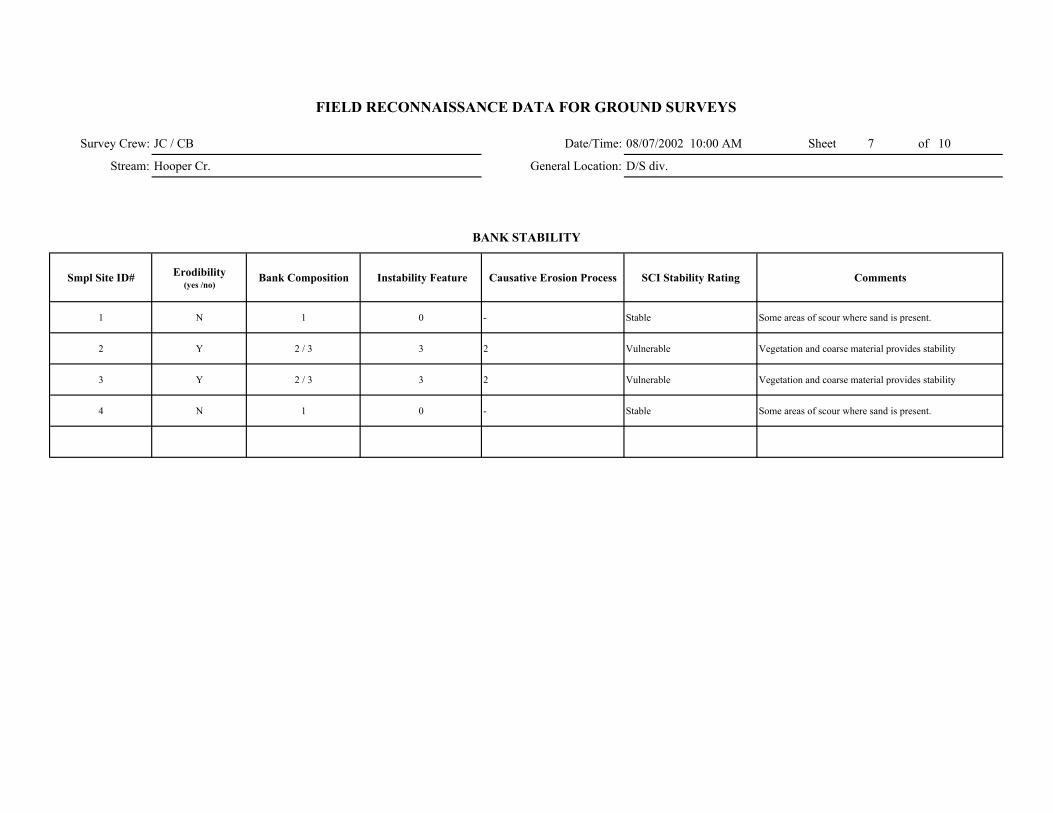
Survey Crew: JC / CB Date/Time: 08/07/2002 10:00 AM Sheet 7 of 10
Stream: Hooper Cr. General Location: D/S div.
Smpl Site ID# Erodibility (yes /no)
Bank Composition Instability Feature Causative Erosion Process SCI Stability Rating Comments
1 N 1 0 - Stable Some areas of scour where sand is present.
2 Y 2 / 3 3 2 Vulnerable Vegetation and coarse material provides stability
3 Y 2 / 3 3 2 Vulnerable Vegetation and coarse material provides stability
4 N 1 0 - Stable Some areas of scour where sand is present.
FIELD RECONNAISSANCE DATA FOR GROUND SURVEYS
BANK STABILITY
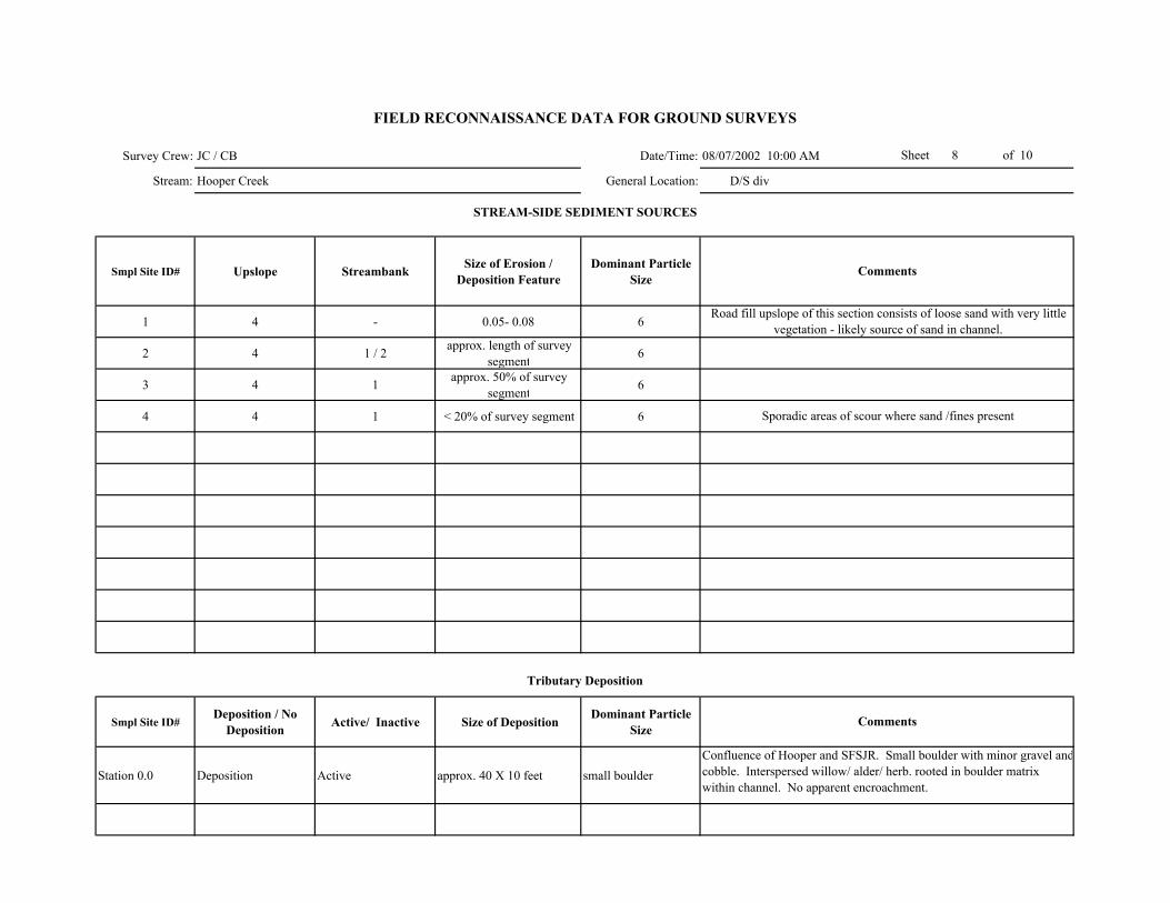
Survey Crew: JC / CB Date/Time: 08/07/2002 10:00 AM
Stream: Hooper Creek General Location: D/S div
Smpl Site ID# Upslope Streambank Size of Erosion / Deposition Feature
Dominant Particle Size
1 4 - 0.05- 0.08 6
2 4 1 / 2 approx. length of survey segment 6
3 4 1 approx. 50% of survey segment 6
4 4 1 < 20% of survey segment 6
Smpl Site ID# Deposition / No
Deposition Active/ Inactive Size of Deposition Dominant Particle Size
Station 0.0 Deposition Active approx. 40 X 10 feet small boulderConfluence of Hooper and SFSJR. Small boulder with minor gravel andcobble. Interspersed willow/ alder/ herb. rooted in boulder matrix within channel. No apparent encroachment.
Sheet 8 of 10
FIELD RECONNAISSANCE DATA FOR GROUND SURVEYS
Comments
Tributary Deposition
STREAM-SIDE SEDIMENT SOURCES
Comments
Road fill upslope of this section consists of loose sand with very little vegetation - likely source of sand in channel.
Sporadic areas of scour where sand /fines present

Survey Crew: JC/ CB Date/Time: 08/07/2002 10:00 AM Sheet 9 of 10
Stream: Hooper Cr. General Location: Downstream of diversion
Smpl Site ID# Presence / Absence Low Flow BF FP Geomorphic Function Recruitment Potential
(High / Moderate / Low)Comments
1 P X X X 3 /4 / 5/ 6 High Abundant conifers and steep slopes along channel.
2 P - - X 3 /6 High Abundant conifers along chanel with relativly low slopes along channel.
3 A - - - - Moderate Moderately dense of conifers with relatively low slopes along channel.
4 P X X X 3 / 5 / 6 Moderate Moderately dense of conifers with relatively low slopes along channel.
FIELD RECONNAISSANCE DATA FOR GROUND SURVEYS
LARGE WOODY DEBRIS
Channel Zone
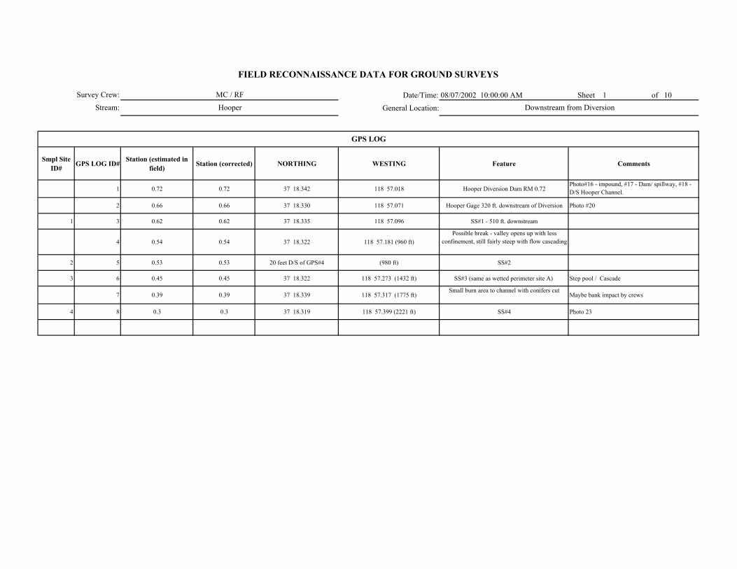
Date/Time: 08/07/2002 10:00:00 AM Sheet 1 of 10
General Location:
Smpl Site ID# GPS LOG ID# Station (estimated in
field) Station (corrected) NORTHING WESTING Feature Comments
1 0.72 0.72 37 18.342 118 57.018 Hooper Diversion Dam RM 0.72Photo#16 - impound, #17 - Dam/ spillway, #18 - D/S Hooper Channel.
2 0.66 0.66 37 18.330 118 57.071 Hooper Gage 320 ft. downstream of Diversion Photo #20
1 3 0.62 0.62 37 18.335 118 57.096 SS#1 - 510 ft. downstream
4 0.54 0.54 37 18.322 118 57.181 (960 ft)Possible break - valley opens up with less
confinement, still fairly steep with flow cascading
2 5 0.53 0.53 20 feet D/S of GPS#4 (980 ft) SS#2
3 6 0.45 0.45 37 18.322 118 57.273 (1432 ft) SS#3 (same as wetted perimeter site A) Step pool / Cascade
7 0.39 0.39 37 18.339 118 57.317 (1775 ft)Small burn area to channel with conifers cut
Maybe bank impact by crews
4 8 0.3 0.3 37 18.319 118 57.399 (2221 ft) SS#4 Photo 23
GPS LOG
Survey Crew:
Stream:
FIELD RECONNAISSANCE DATA FOR GROUND SURVEYS
MC / RF
Hooper Downstream from Diversion

Survey Crew: MC / RF 08/07/2002 10:00:00 AM Sheet 2 of 10
Stream: Hooper DS Div.
ER W/D Conf.
Station to Station Smpl Site ID#
Wbf
Ave BF depth
(AveDbf)
Max BF depth
Wfp Wv Wfp /Wbf AveDbf /Wbf Wv /Wbf V U ( BF FP Wv
Bed-Form Montg.-Buffingt.
Stream Type
RosgenComments GPS LOG
ID#
0.65- 0.62 1 8.5 0.6 1.2 12 - 1.4 14 - X H M - 2 (3) A2a+/A1a+ approx. 20% slope 3
0.54- 0.52 2 15 0.5 0.9 21 - 1.4 30 - X M M - 4 B2Appears less entrenched than measured due to flood attenuation by diversion. 5
0.50- 0.45 3 8.5 0.8 1.5 16.5 - 1.9 10.63 - X M M - 3 B2, A2a+Site behind LWD jam at gravel bar in depositional area 6
0.35- 0.30 4 6.5 1.2 1.8 13 - 2 5.4 - X M M - 2/3 A2a+ High gradient 8
FIELD RECONNAISSANCE DATA FOR GROUND SURVEYS
Degree of Confidence
CHANNEL ENTRENCHMENT, VALLEY CONFINEMENT, BED-FORM, and CHANNEL CLASSIFICATION
Valley Shape
Date/Time:
General Location:

MC / RF Date/Time: 08/07/2002 10:00:00 AM
Hooper General Location: Downstream diversion
DOMINANT STREAMBED PARTICLE SIZE
GPS ID Smpl Site ID# Bedrock Lg. Boulder (512-4096 mm)
Sm. Boulder (256-512 mm)
Cobble (64-256 mm)
Gravel (2-64 mm)
Sand/ Fines (<2mm)
3 1 25 40 15 10 5 5
5 2 - 15 30 35 10 10
6 3 - 40 30 20 5 5
4 - 50 30 10 - 10
FIELD RECONNAISSANCE DATA FOR GROUND SURVEYS
Sheet 3 of 10
Comments
Survey Crew:
Stream:

Survey Crew: MC /RF 08/07/2002 10:00:00 AMStream: Hooper Downstream diverson
Smpl Site ID# Boulder
Shadow (none, few, many)
Bars (# in unit)
Pool Tail-Out/ Riffle
Associated with LWD
Scattered, Poorly Sorted
Boulder Shadow (none,
few, many)Bars (# in unit)
Associated with LWD
Interstitial spaces filled
Concentrated, Covering Bed
Pools (% on bed)
Comments
1 None 1 N Y Y Few 0 Y Y N 15 LWD is few
2 None - - _ Y None 1 Y Y (few) N 40 LWD makes pool with sand dep.
3 None 2 N Y Y Few - N Y (few) N 20
4 None - - - Y Few - Y Y N 40 LWD with sand dep.
Lateral Mid-channel Point
1 P 1 X
2 P 1 X
3 P 2 X
4 A - - - -
Comments
Sand Deposits
INSTREAM BARS
Presence/ Absence Count Active / Inactive Bar Particle Size Comp
Bar Type
FIELD RECONNAISSANCE DATA FOR GROUND SURVEYS
Date/Time:General Location:
Sheet 4 of 10
GRAVEL and SAND DEPOSITIONAL FEATURESGravel Deposits
Smpl Site ID#
5 X 10 ft.
15 X 10 ft. Dep. behind LWD jam
15 X 5 ft. formed by LWD jam
-
gravel
sand
gravel
-
active
active
active
-
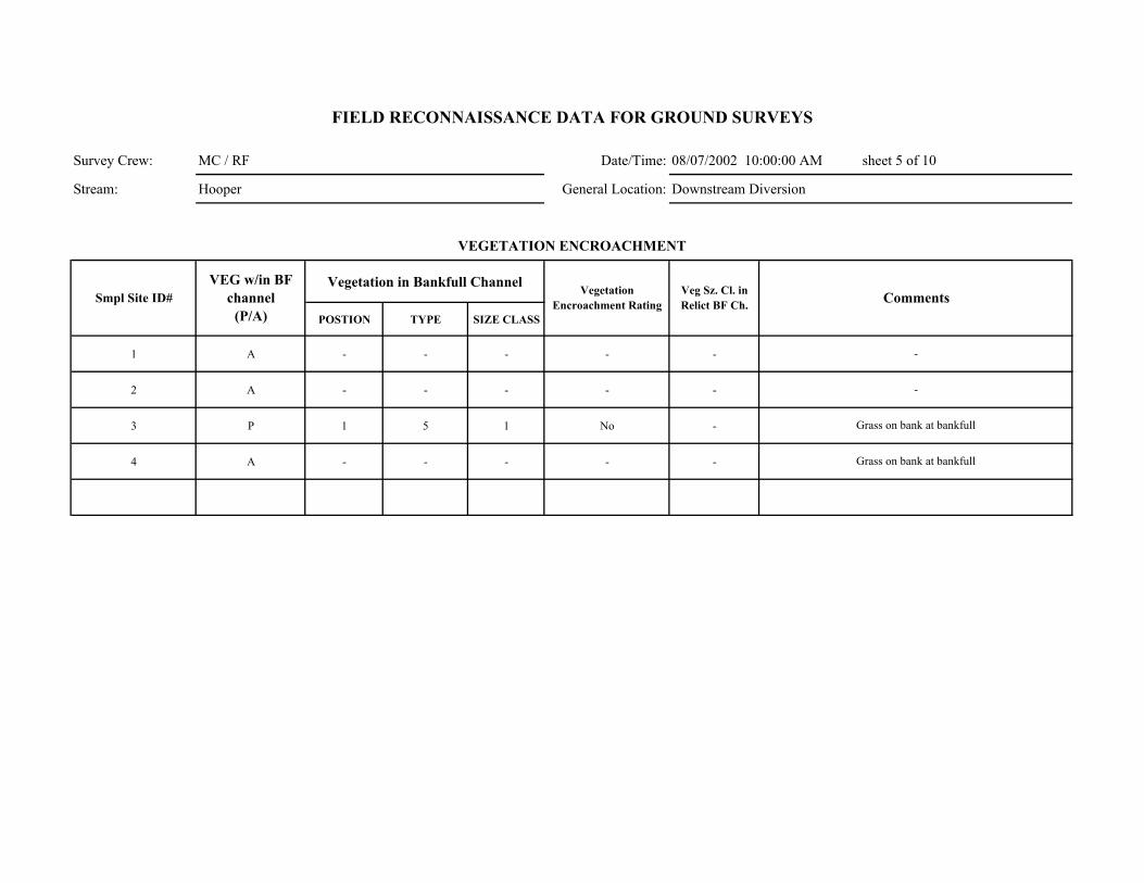
Survey Crew: MC / RF Date/Time: 08/07/2002 10:00:00 AM sheet 5 of 10
Stream: Hooper General Location: Downstream Diversion
Vegetation in Bankfull Channel
POSTION TYPE SIZE CLASS
1 A - - - - -
2 A - - - - -
3 P 1 5 1 No -
4 A - - - - -
Comments
VEGETATION ENCROACHMENT
FIELD RECONNAISSANCE DATA FOR GROUND SURVEYS
Smpl Site ID# VEG w/in BF
channel (P/A)
Vegetation Encroachment Rating
Veg Sz. Cl. in Relict BF Ch.
-
-
Grass on bank at bankfull
Grass on bank at bankfull
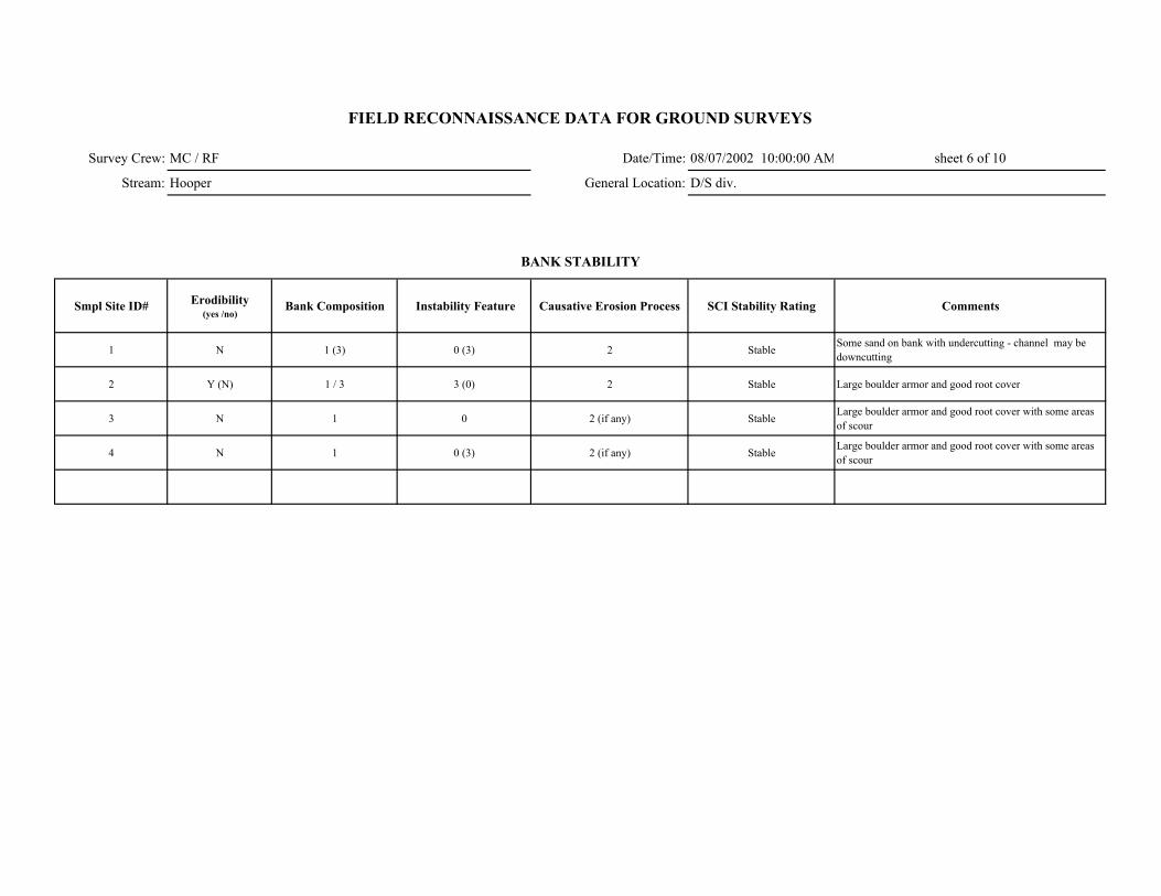
Survey Crew: MC / RF Date/Time: 08/07/2002 10:00:00 AM sheet 6 of 10
Stream: Hooper General Location: D/S div.
Smpl Site ID# Erodibility (yes /no)
Bank Composition Instability Feature Causative Erosion Process SCI Stability Rating Comments
1 N 1 (3) 0 (3) 2 Stable Some sand on bank with undercutting - channel may be downcutting
2 Y (N) 1 / 3 3 (0) 2 Stable Large boulder armor and good root cover
3 N 1 0 2 (if any) Stable Large boulder armor and good root cover with some areas of scour
4 N 1 0 (3) 2 (if any) Stable Large boulder armor and good root cover with some areas of scour
FIELD RECONNAISSANCE DATA FOR GROUND SURVEYS
BANK STABILITY
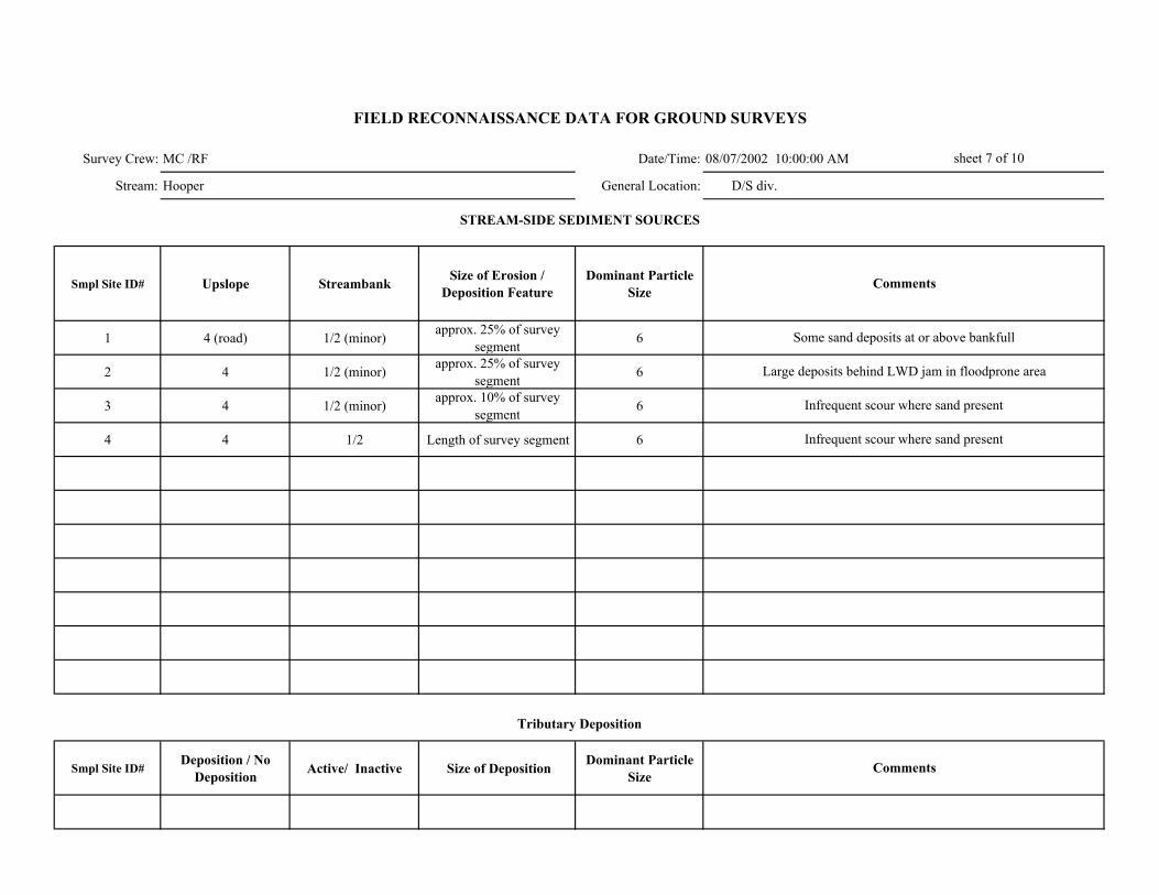
Survey Crew: MC /RF Date/Time: 08/07/2002 10:00:00 AM
Stream: Hooper General Location: D/S div.
Smpl Site ID# Upslope Streambank Size of Erosion / Deposition Feature
Dominant Particle Size
1 4 (road) 1/2 (minor) approx. 25% of survey segment 6
2 4 1/2 (minor) approx. 25% of survey segment 6
3 4 1/2 (minor) approx. 10% of survey segment 6
4 4 1/2 Length of survey segment 6
Smpl Site ID# Deposition / No
Deposition Active/ Inactive Size of Deposition Dominant Particle Size
sheet 7 of 10
FIELD RECONNAISSANCE DATA FOR GROUND SURVEYS
Comments
Tributary Deposition
STREAM-SIDE SEDIMENT SOURCES
Comments
Some sand deposits at or above bankfull
Large deposits behind LWD jam in floodprone area
Infrequent scour where sand present
Infrequent scour where sand present
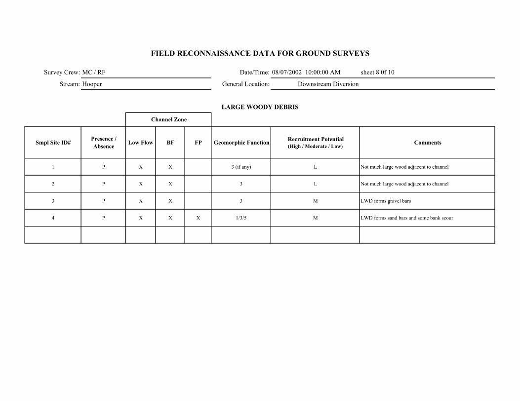
Survey Crew: MC / RF Date/Time: 08/07/2002 10:00:00 AM sheet 8 0f 10
Stream: Hooper General Location: Downstream Diversion
Smpl Site ID# Presence / Absence Low Flow BF FP Geomorphic Function Recruitment Potential
(High / Moderate / Low)Comments
1 P X X 3 (if any) L Not much large wood adjacent to channel
2 P X X 3 L Not much large wood adjacent to channel
3 P X X 3 M LWD forms gravel bars
4 P X X X 1/3/5 M LWD forms sand bars and some bank scour
FIELD RECONNAISSANCE DATA FOR GROUND SURVEYS
LARGE WOODY DEBRIS
Channel Zone
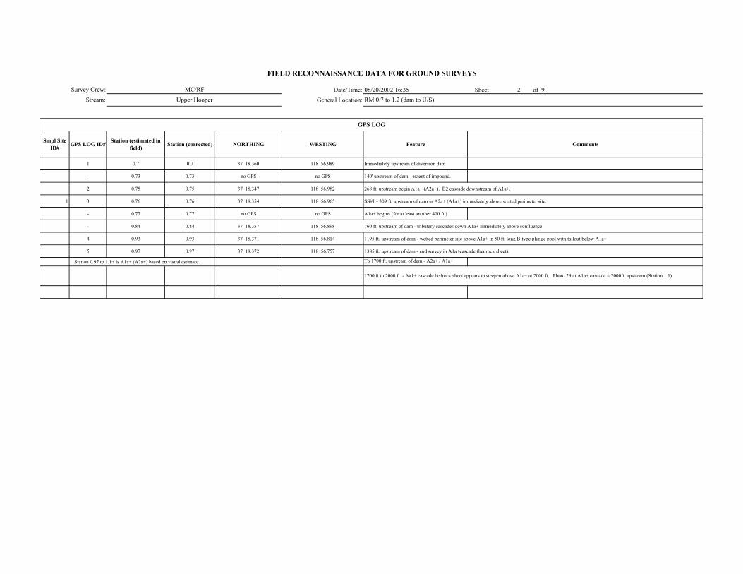
Date/Time: 08/20/2002 16:35 Sheet 2 of 9General Location:
Smpl Site ID# GPS LOG ID# Station (estimated in
field) Station (corrected) NORTHING WESTING Feature Comments
1 0.7 0.7 37 18.360 118 56.989 Immediately upstream of diversion dam
- 0.73 0.73 no GPS no GPS 140' upstream of dam - extent of impound.
2 0.75 0.75 37 18.347 118 56.982 268 ft. upstream begin A1a+ (A2a+). B2 cascade downstream of A1a+.
1 3 0.76 0.76 37 18.354 118 56.965 SS#1 - 309 ft. upstream of dam in A2a+ (A1a+) immediately above wetted perimeter site.
- 0.77 0.77 no GPS no GPS A1a+ begins (for at least another 400 ft.)
- 0.84 0.84 37 18.357 118 56.898 760 ft. upstream of dam - tributary cascades down A1a+ immediately above confluence
4 0.93 0.93 37 18.371 118 56.814 1195 ft. upstream of dam - wetted perimeter site above A1a+ in 50 ft. long B-type plunge pool with tailout below A1a+
5 0.97 0.97 37 18.372 118 56.757 1385 ft. upstream of dam - end survey in A1a+ cascade (bedrock sheet).
Station 0.97 to 1.1+ is A1a+ (A2a+) based on visual estimate To 1700 ft. upstream of dam - A2a+ / A1a+
FIELD RECONNAISSANCE DATA FOR GROUND SURVEYS
MC/RFUpper Hooper RM 0.7 to 1.2 (dam to U/S)
1700 ft to 2000 ft. - Aa1+ cascade bedrock sheet appears to steepen above A1a+ at 2000 ft. Photo 29 at A1a+ cascade ~ 2000ft. upstream (Station 1.1)
GPS LOG
Survey Crew:Stream:

Survey Crew: MC/ RF 08/20/2002 16:35 sheet 3 of 9
Stream: Upper Hooper
ER W/D Conf.
Station to Station Smpl Site ID#
Wbf
Ave BF depth
(AveDbf)
Max BF depth
Wfp Wv Wfp /Wbf AveDbf /Wbf Wv /Wbf V U ( BF FP Wv
Bed-Form Montg.-Buffingt.
Stream Type Rosgen Comments GPS LOG ID#
0.73- 0.76 1 14.5 0.7 1.2 23.5 - 1.62 20.7 - X - M M - 2 A2a+ (with B2 characteristics) >10% gradient 3
FIELD RECONNAISSANCE DATA FOR GROUND SURVEYS
Degree of Confidence
CHANNEL ENTRENCHMENT, VALLEY CONFINEMENT, BED-FORM, and CHANNEL CLASSIFICATION
Valley Shape
Date/Time:
General Location: RM 0.7 to 1.2 (dam to U/S)

MC/ RF Date/Time: 08/20/2002 16:35
Upper Hooper General Location:
DOMINANT STREAMBED PARTICLE SIZE
Smpl Site ID# Smpl Site ID# Bedrock Lg. Boulder (512-4096 mm)
Sm. Boulder (256-512 mm)
Cobble (64-256 mm)
Gravel (2-64 mm)
Sand/ Fines (<2mm)
1 20 20 30 15 10 5
RM 0.7 to 1.2 (dam to U/S)
Survey Crew:
Stream:
FIELD RECONNAISSANCE DATA FOR GROUND SURVEYS
sheet 4 of 9
Comments

Survey Crew: MC/ RF 08/20/2002 16:35 Stream: Upper Hooper
Smpl Site ID# Boulder
Shadow (none, few, many)
Bars (# in unit)
Pool Tail-Out/ Riffle
Associated with LWD
Scattered, Poorly Sorted
Boulder Shadow (none,
few, many)Bars (# in unit)
Associated with LWD
Interstitial spaces filled
Concentrated, Covering Bed
Pools (% on bed)
Comments
1 few - N N Y N - N Y N 5 no pools
Lateral Mid-channel Point
1 A - - - -
RM 0.7 to 1.2 (dam to U/S)
- - No bars
FIELD RECONNAISSANCE DATA FOR GROUND SURVEYS
Date/Time:General Location:
sheet 5 of 9
GRAVEL and SAND DEPOSITIONAL FEATURESGravel Deposits
Smpl Site ID# Comments
Sand Deposits
INSTREAM BARS
Presence/ Absence Count Active / Inactive Bar Particle Size Comp
Bar Type
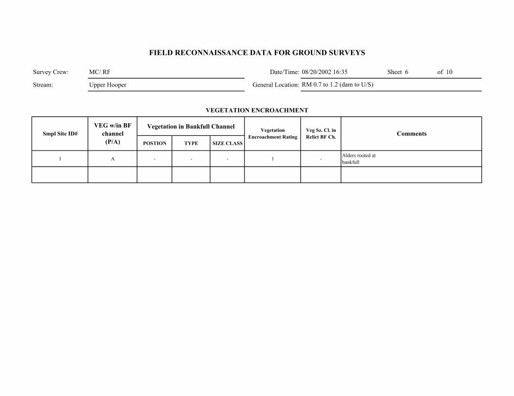
Survey Crew: MC/ RF Date/Time: 08/20/2002 16:35 Sheet 6 of 10
Stream: Upper Hooper General Location:
Vegetation in Bankfull Channel
POSTION TYPE SIZE CLASS
1 A - - - 1 -Alders rooted at bankfull
Comments
VEGETATION ENCROACHMENT
FIELD RECONNAISSANCE DATA FOR GROUND SURVEYS
Smpl Site ID# VEG w/in BF
channel (P/A)
Vegetation Encroachment Rating
Veg Sz. Cl. in Relict BF Ch.
RM 0.7 to 1.2 (dam to U/S)

Survey Crew: MC/ RF Date/Time: 08/20/2002 16:35 sheet 7 of 10
Stream: Upper Hooper General Location:
Smpl Site ID# Erodibility (yes /no)
Bank Composition Instability Feature Causative Erosion Process SCI Stability Rating Comments
1 N 1/2 (3) 0 3 (1) stable
FIELD RECONNAISSANCE DATA FOR GROUND SURVEYS
BANK STABILITY
RM 0.7 to 1.2 (dam to U/S)

Survey Crew: MC/ RF Date/Time: 08/20/2002 16:35
Stream: Upper Hooper General Location:
Smpl Site ID# Upslope Streambank Size of Erosion / Deposition Feature
Dominant Particle Size
1 4 1 <5 % of survey segment Sand
Smpl Site ID# Deposition / No
Deposition Active/ Inactive Size of Deposition Dominant Particle Size
RM 0.7 to 1.2 (dam to U/S)
Sheet 8 of 10
FIELD RECONNAISSANCE DATA FOR GROUND SURVEYS
Comments
Tributary Deposition
STREAM-SIDE SEDIMENT SOURCES
Comments
No real erosion or sediment
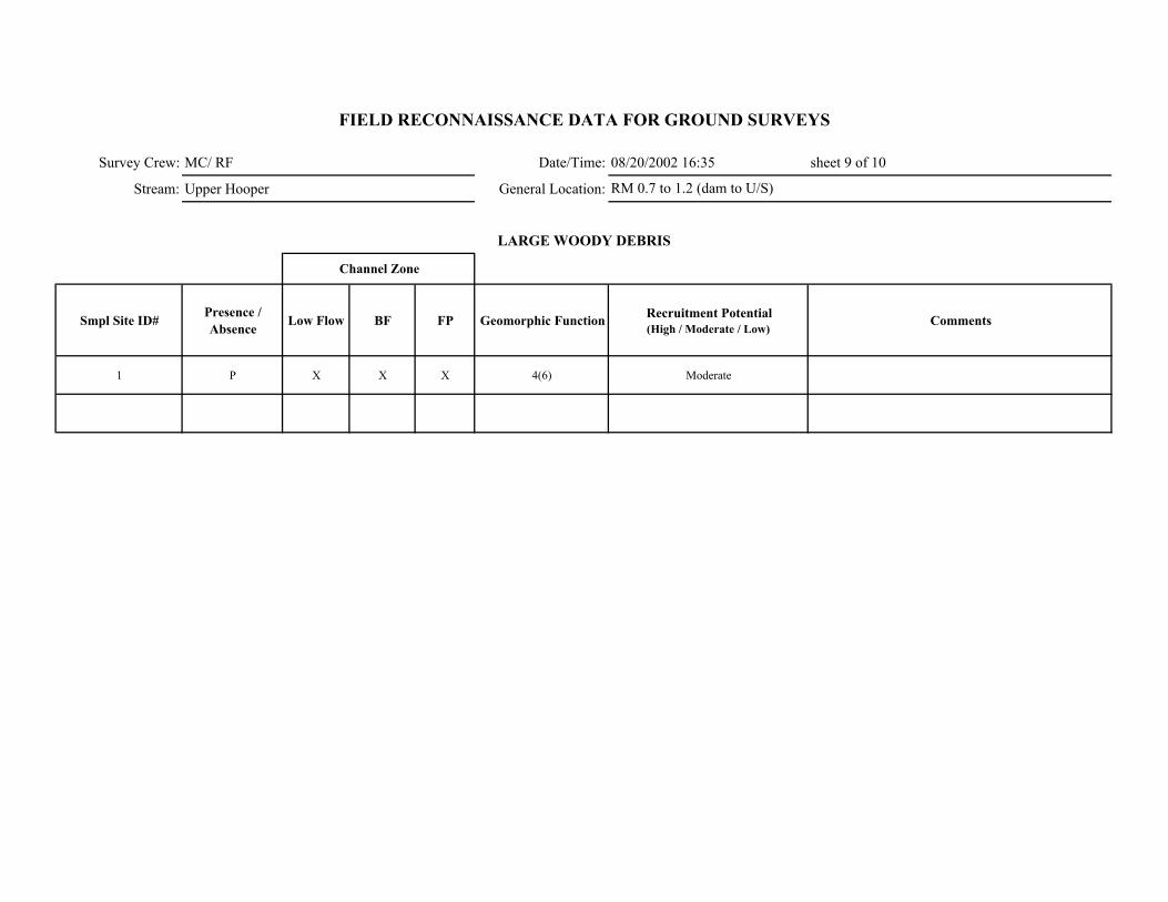
Survey Crew: MC/ RF Date/Time: 08/20/2002 16:35 sheet 9 of 10
Stream: Upper Hooper General Location:
Smpl Site ID# Presence / Absence Low Flow BF FP Geomorphic Function Recruitment Potential
(High / Moderate / Low)Comments
1 P X X X 4(6) Moderate
FIELD RECONNAISSANCE DATA FOR GROUND SURVEYS
LARGE WOODY DEBRIS
Channel Zone
RM 0.7 to 1.2 (dam to U/S)
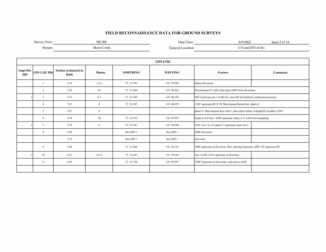
Date/Time: 9/9/2002 sheet 2 of 10
General Location:
Smpl Site ID# GPS LOG ID# Station (estimated in
field) Photos NORTHING WESTING Feature Comments
1 5.79 1,2,3 37 21.593 118 59.903 Mono Diversion
2 5.29 4,5 37 21.469 119 00.262 Downstream 0.5 mile (hip chain 2640' from diversion)
1 3 5.33 6,7 37 21.550 119 00.193 205' Upstream site 1 in B2/A2, most B2 but bedrock confinement present
4 5.55 8 37 21.507 119 00.079 1385' upstream 80' X 30' Mid-channel/lateral bar- photo 8
5 5.67 9 - - photo 9- Mid-channel bars with 1 class alder/willow at bankfull, boulders 1999'
6 5.74 10 37 21.555 118 59.959 break to A2/A2a+ 2409' upstream valley is V with local steepining
2 7 5.78 11 37 21.581 118 59.948 2591' site 2 in A2 photo 11 upstream from site 2
8 5.82 See GPS 1 See GPS 1 2808' diversion
5.79 See GPS 1 See GPS 1 diversion
9 5.98 37 21.565 118 59.725
3 10 6.21 14,15 37 21.693 118 59.618 site 3 in B2 2216' upstream of diversion
11 6.29 37 21.710 118 59.567 2700' Upstream of diversion- end survey in B2
FIELD RECONNAISSANCE DATA FOR GROUND SURVEYS
MC/RF
Mono Creek U/S and D/S of div.
1000' upstream of diversion, flow entering impound- riffle 150' upstream B2
GPS LOG
Survey Crew:
Stream:

Survey Crew: MC/RF 9/9/2002 Sheet 3 of 10
Stream: Mono Cr. u/s and d/s of diversion
ER W/D Conf.
Station to Station Smpl Site ID#
WbfAve BF depth
(AveDbf)Max BF
depthWfp Wv Wfp /Wbf AveDbf /Wbf Wv /Wbf V U ( BF FP Wv
Bed-Form Montg.-Buffingt.
Stream Type
RosgenComments GPS LOG
ID#
5.29-5.33 1 40' 2.3 3 55-60 - 1.45 17.4 - X X - L/M L/M - 4(3) B2some areas more entrenched. Poor indicators- willow root position 3
5.74-5.79 2 27' 3.2 4.3 37 38 1.37 8.43 - X M M - 4/3 A2 8-12% localized A2a+ 7
5.98-6.24 3 60' 4.5 3 95 - 1.6 20 - X M/H M - 4 B2 gross visual estimate - flowing 1' below bankfull 10
FIELD RECONNAISSANCE DATA FOR GROUND SURVEYS
Degree of Confidence
CHANNEL ENTRENCHMENT, VALLEY CONFINEMENT, BED-FORM, and CHANNEL CLASSIFICATION
Valley Shape
Date/Time:
General Location:

MC/RF Date/Time: 9/9/2002
Mono Cr. General Location: Upstream and downstream of diversion
DOMINANT STREAMBED PARTICLE SIZE
gps Smpl Site ID# Bedrock Lg. Boulder (512-4096 mm)
Sm. Boulder (256-512 mm)
Cobble (64-256 mm)
Gravel (2-64 mm)
Sand/ Fines (<2mm)
3 1 5 65 20 5 2.5 2.5
7 2 60 30 10 10
10 3 - 60 20 10 5 5
Survey Crew:
Stream:
silt/sand interstitial and shallow
FIELD RECONNAISSANCE DATA FOR GROUND SURVEYS
sheet 4 of 10
Comments

Survey Crew: MC/RF 9/9/2002Stream: Mono Cr. and d/s of div.
Smpl Site ID# Boulder
Shadow (none, few, many)
Bars (# in unit)
Pool Tail-Out/ Riffle
Associated with LWD
Scattered, Poorly Sorted
Boulder Shadow (none,
few, many)Bars (# in unit)
Associated with LWD
Interstitial spaces filled
Concentrated, Covering Bed
Pools (% on bed)
Comments
1 few 0 N N Y few/none 0 N N(Y) N <5 not much fines
2 none 0 N N Y many 0 N Y N 40 sand between boulders
3 few 1 N Y Y few/none 0 N Y(N) N <5? difficult to see any sand
Lateral Mid-channel Point
1 A - - - -
2 A - - - -
3 P 3 2 1
-
-
active
-
-
gravel/ cobble
no bars/upstream 2 bars
1 gravel bar (Mid-channel) LWD/ boulder shadow/ 2 cobble lateral point bars.
FIELD RECONNAISSANCE DATA FOR GROUND SURVEYS
Date/Time:General Location:
sheet 5 of 10
GRAVEL and SAND DEPOSITIONAL FEATURESGravel Deposits
Smpl Site ID# Comments
Sand Deposits
INSTREAM BARS
Presence/ Absence Count Active / Inactive Bar Particle Size Comp
Bar Type
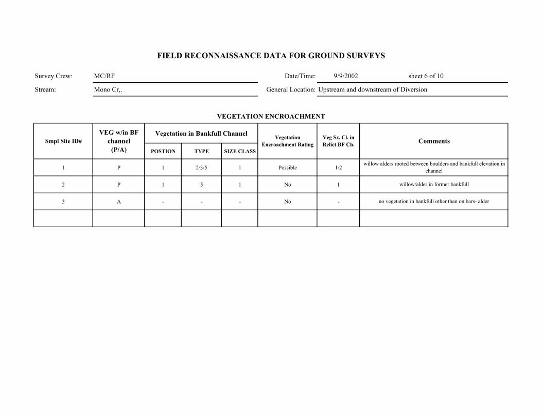
Survey Crew: MC/RF Date/Time: 9/9/2002 sheet 6 of 10
Stream: Mono Cr,. General Location: Upstream and downstream of Diversion
Vegetation in Bankfull Channel
POSTION TYPE SIZE CLASS
1 P 1 2/3/5 1 Possible 1/2
2 P 1 5 1 No 1
3 A - - - No -
willow alders rooted between boulders and bankfull elevation in channel
willow/alder in former bankfull
no vegetation in bankfull other than on bars- alder
Comments
VEGETATION ENCROACHMENT
FIELD RECONNAISSANCE DATA FOR GROUND SURVEYS
Smpl Site ID# VEG w/in BF
channel (P/A)
Vegetation Encroachment Rating
Veg Sz. Cl. in Relict BF Ch.
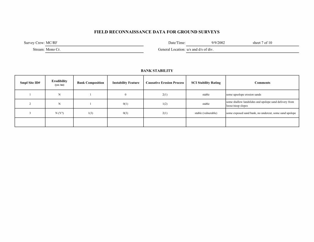
Survey Crew: MC/RF Date/Time: 9/9/2002 sheet 7 of 10
Stream: Mono Cr. General Location: u/s and d/s of div.
Smpl Site ID# Erodibility (yes /no)
Bank Composition Instability Feature Causative Erosion Process SCI Stability Rating Comments
1 N 1 0 2(1) stable some upsolope erosion sands
2 N 1 0(1) 1(2) stable some shallow landslides and upslope sand delivery from loose/steep slopes
3 N (Y?) 1(3) 0(3) 2(1) stable (vulnerable) some exposed sand bank, no undercut, some sand upslope
FIELD RECONNAISSANCE DATA FOR GROUND SURVEYS
BANK STABILITY

Survey Crew: MC/RF Date/Time: 9/9/2002
Stream: Mono Cr. General Location:and d/s of div.
Smpl Site ID# Upslope Streambank Size of Erosion / Deposition Feature
Dominant Particle Size
1 4 if any 1 if any <5% unit sand
2 4 (1,2) 1 if any 30% unit sand/ angular cobble
3 4 1 if any 10% unit sand
Smpl Site ID# Deposition / No
Deposition Active/ Inactive Size of Deposition Dominant Particle Size
sheet 8 of 10
FIELD RECONNAISSANCE DATA FOR GROUND SURVEYS
Comments
Tributary Deposition
STREAM-SIDE SEDIMENT SOURCES
Comments
no deposits or erosion per se
sand and angular cobble from upslope
some sand and boulder bank- upslope sand delivery- no deposits
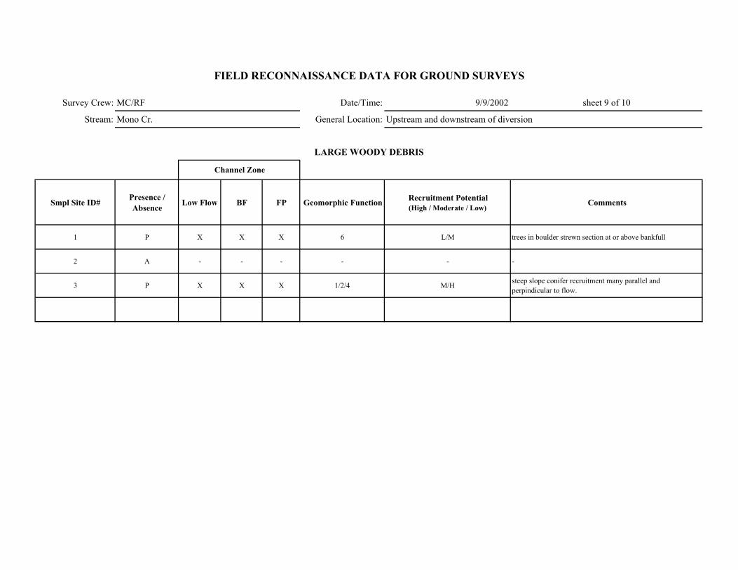
Survey Crew: MC/RF Date/Time: 9/9/2002 sheet 9 of 10
Stream: Mono Cr. General Location: Upstream and downstream of diversion
Smpl Site ID# Presence / Absence Low Flow BF FP Geomorphic Function Recruitment Potential
(High / Moderate / Low)Comments
1 P X X X 6 L/M trees in boulder strewn section at or above bankfull
2 A - - - - - -
3 P X X X 1/2/4 M/H steep slope conifer recruitment many parallel and perpindicular to flow.
FIELD RECONNAISSANCE DATA FOR GROUND SURVEYS
LARGE WOODY DEBRIS
Channel Zone
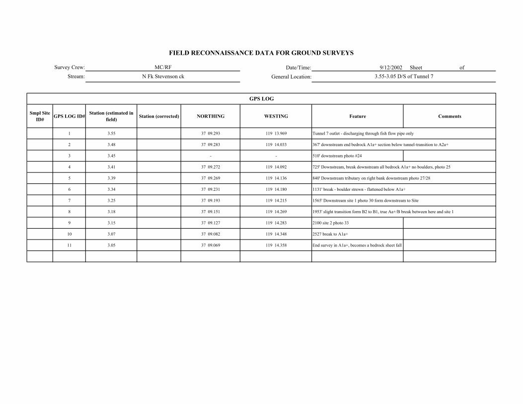
Date/Time: 9/12/2002 Sheet of
General Location:
Smpl Site ID# GPS LOG ID# Station (estimated in
field) Station (corrected) NORTHING WESTING Feature Comments
1 3.55 37 09.293 119 13.969 Tunnel 7 outlet - discharging through fish flow pipe only
2 3.48 37 09.283 119 14.033 367' downstream end bedrock A1a+ section below tunnel-transition to A2a+
3 3.45 - - 510' downstream photo #24
4 3.41 37 09.272 119 14.092 725' Downstream, break downstream all bedrock A1a+ no boulders, photo 25
5 3.39 37 09.269 119 14.136 840' Downstream tributary on right bank downstream photo 27/28
6 3.34 37 09.231 119 14.180 1131' break - boulder strewn - flattened below A1a+
7 3.25 37 09.193 119 14.215 1565' Downstream site 1 photo 30 form downstream to Site
8 3.18 37 09.151 119 14.269 1953' slight transition form B2 to B1, true Aa+/B break between here and site 1
9 3.15 37 09.127 119 14.283 2100 site 2 photo 33
10 3.07 37 09.082 119 14.348 2527 break to A1a+
11 3.05 37 09.069 119 14.358 End survey in A1a+, becomes a bedrock sheet fall
GPS LOG
Survey Crew:
Stream:
FIELD RECONNAISSANCE DATA FOR GROUND SURVEYS
MC/RF
N Fk Stevenson ck 3.55-3.05 D/S of Tunnel 7
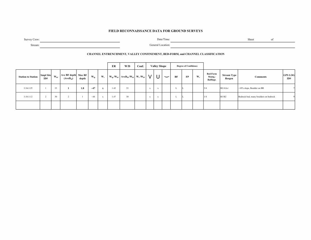
Survey Crew: Sheet of
Stream:
ER W/D Conf.
Station to Station Smpl Site ID#
WbfAve BF depth
(AveDbf)Max BF
depthWfp Wv Wfp /Wbf AveDbf /Wbf Wv /Wbf V U ( BF FP Wv
Bed-Form Montg.-Buffingt.
Stream Type Rosgen Comments GPS LOG
ID#
3.34-3.25 1 33 1 1.8 ~47 x 1.42 33 x x L L 3/4 B2/A2a+ ~10% slope, Boulder on BR 7
3.18-3.12 2 30 2 1 ~44 x 1.47 30 x x L L 1/4 B1/B2 Bedrock bed, many boulders on bedrock 9
FIELD RECONNAISSANCE DATA FOR GROUND SURVEYS
Degree of Confidence
CHANNEL ENTRENCHMENT, VALLEY CONFINEMENT, BED-FORM, and CHANNEL CLASSIFICATION
Valley Shape
Date/Time:
General Location:

Date/Time:
General Location:
DOMINANT STREAMBED PARTICLE SIZE
Smpl Site ID# Smpl Site ID# Bedrock Lg. Boulder (512-4096 mm)
Sm. Boulder (256-512 mm)
Cobble (64-256 mm)
Gravel (2-64 mm)
Sand/ Fines (<2mm)
7 1 15 55 15 10 2.5 2.5
9 2 35 25 25 10 4 1
Survey Crew:
Stream:
Bedrock controlled and bed - B2
FIELD RECONNAISSANCE DATA FOR GROUND SURVEYS
Sheet of
Comments
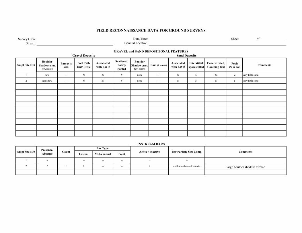
Survey Crew:Stream:
Smpl Site ID# Boulder
Shadow (none, few, many)
Bars (# in unit)
Pool Tail-Out/ Riffle
Associated with LWD
Scattered, Poorly Sorted
Boulder Shadow (none,
few, many)Bars (# in unit)
Associated with LWD
Interstitial spaces filled
Concentrated, Covering Bed
Pools (% on bed)
Comments
1 few -- N N Y none -- N N N 2 very little sand
2 none/few -- N N Y none -- N N N 5 very little sand
Lateral Mid-channel Point
1 A -- -- --
2 P 1 1 -- --
--
?
--
cobble with small boulder large boulder shadow formed
FIELD RECONNAISSANCE DATA FOR GROUND SURVEYS
Date/Time:General Location:
Sheet of
GRAVEL and SAND DEPOSITIONAL FEATURESGravel Deposits
Smpl Site ID# Comments
Sand Deposits
INSTREAM BARS
Presence/ Absence Count Active / Inactive Bar Particle Size Comp
Bar Type
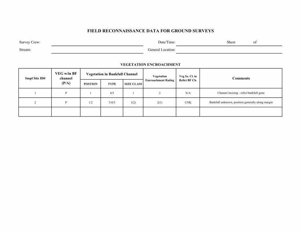
Survey Crew: Date/Time: Sheet of
Stream: General Location:
Vegetation in Bankfull Channel
POSTION TYPE SIZE CLASS
1 P 1 4/5 1 2 N/A
2 P 1/2 3/4/5 1(2) 2(1) UNK
FIELD RECONNAISSANCE DATA FOR GROUND SURVEYS
Smpl Site ID# VEG w/in BF
channel (P/A)
Vegetation Encroachment Rating
Veg Sz. Cl. in Relict BF Ch.
Channel incising - relict bankfull gone
Bankfull unknown, position generally along margin
Comments
VEGETATION ENCROACHMENT
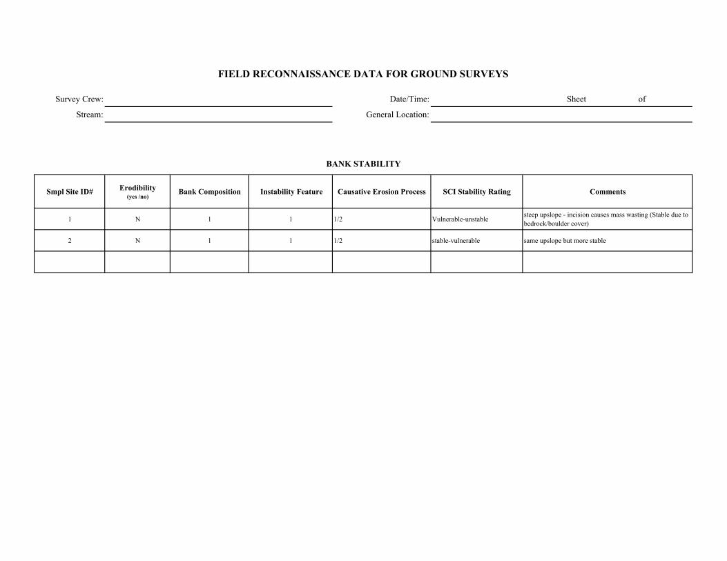
Survey Crew: Date/Time: Sheet of
Stream: General Location:
Smpl Site ID# Erodibility (yes /no)
Bank Composition Instability Feature Causative Erosion Process SCI Stability Rating Comments
1 N 1 1 1/2 Vulnerable-unstable steep upslope - incision causes mass wasting (Stable due to bedrock/boulder cover)
2 N 1 1 1/2 stable-vulnerable same upslope but more stable
FIELD RECONNAISSANCE DATA FOR GROUND SURVEYS
BANK STABILITY

Survey Crew: Date/Time:
Stream: General Location:
Smpl Site ID# Upslope Streambank Size of Erosion / Deposition Feature
Dominant Particle Size
1 1/4 2 if any 80% of unit sand
2 1/4 3 if any 30% of unit sand
Smpl Site ID# Deposition / No
Deposition Active/ Inactive Size of Deposition Dominant Particle Size
Sheet of
FIELD RECONNAISSANCE DATA FOR GROUND SURVEYS
Comments
Tributary Deposition
STREAM-SIDE SEDIMENT SOURCES
Comments
upslope banks actively delivering to incised channel
upslope banks actively delivering to incised channel but less frequent due to bedrock
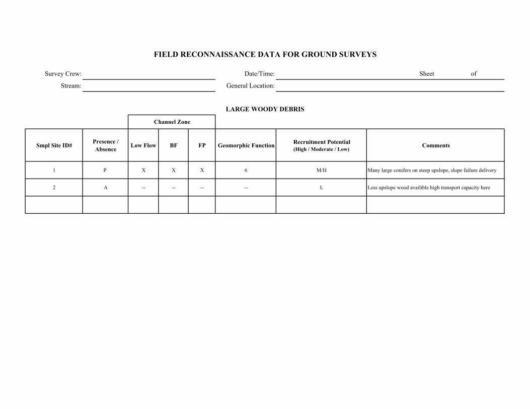
Survey Crew: Date/Time: Sheet of
Stream: General Location:
Smpl Site ID# Presence / Absence Low Flow BF FP Geomorphic Function Recruitment Potential
(High / Moderate / Low)Comments
1 P X X X 6 M/H Many large conifers on steep upslope, slope failure delivery
2 A -- -- -- -- L Less upslope wood availible high transport capacity here
FIELD RECONNAISSANCE DATA FOR GROUND SURVEYS
LARGE WOODY DEBRIS
Channel Zone
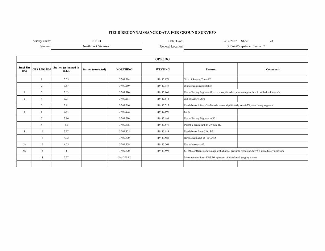
Date/Time: 9/12/2002 Sheet of General Location:
Smpl Site ID# GPS LOG ID# Station (estimated in
field) Station (corrected) NORTHING WESTING Feature Comments
1 3.55 37 09.294 119 13.970 Start of Survey, Tunnel 7
2 3.57 37 09.289 119 13.949 abandoned gauging station
1 3 3.63 37 09.310 119 13.900 End of Survey Segment #1, start survey in A1a+, upstream goes into A1a+ bedrock cascade
2 4 3.71 37 09.291 119 13.814 end of Survey SS#2
5 3.81 37 09.266 119 13.725 Reach break A1a+, Gradient decreases significantly to ~ 4-5%, start survey segment
3 6 3.84 37 09.272 119 13.697 SS #3
7 3.86 37 09.290 119 13.691 End of Survey Segment in B2
8 3.9 37 09.336 119 13.676 Potential reach bank to C? from B2
4 10 3.97 37 09.355 119 13.614 Reach break from C5 to B2
11 4.02 37 09.370 119 13.589 Downstream end of 100' of E5
5a 12 4.05 37 09.359 119 13.561 End of survey ss#5
5b 13 4 37 09.370 119 13.592 SS #5b confluence of drainage with channel probable form road, SS# 5b immediately upstream
14 3.57 See GPS #2 Measurements form SS#1 10' upstream of abandoned gauging station
GPS LOG
Survey Crew:Stream:
FIELD RECONNAISSANCE DATA FOR GROUND SURVEYS
JC/CBNorth Fork Stevnson 3.55-4.05 upstream Tunnel 7

Survey Crew: Sheet of
Stream:
ER W/D Conf.
Station to Station Smpl Site ID#
WbfAve BF depth
(AveDbf)Max BF
depthWfp Wv Wfp /Wbf AveDbf /Wbf Wv /Wbf V U ( BF FP Wv
Bed-Form Montg.-Buffingt.
Stream Type Rosgen Comments GPS
LOG ID#
3.55-3.63 1 7.5 0.5 0.9 7 0.43 12.5 -- x 2/3 A2a+/A2 gradient 8-12%, steep banks along channel opens up, upslope
3.63-3.71 2 15 0.5 0.7 18 1.2 30 -- x M M -- 1/2 A1a+ gradient steepens, bedrock channel, sheet flow over bedrock gradient 20-30%
3.81-3.86 3 9 0.7 0.9 20 2.2 12.9 x H H -- 4 B2 gradient decreases Significantly Above to 4-5% A1a+
3.90-3.97 4a 4.4 0.35 0.6 30 6.8 12.6 x H H -- 4/5 C5 gradient decreases, moderately sinuosity, "point bars" - like flood prone area
4b 9.5 0.35 0.6 24 2.5 27.1 x H H -- 4/5 C5
3.97-4.05 5a 4.7 0.5 0.7 9.5 2.02 9.4 H H -- 4 B5 moderate Sinuosity
5b 5.8 0.5 0.6 12 2.07 9.6 M M -- 4 B5 moderate Sinuosity
FIELD RECONNAISSANCE DATA FOR GROUND SURVEYS
Degree of Confidence
CHANNEL ENTRENCHMENT, VALLEY CONFINEMENT, BED-FORM, and CHANNEL CLASSIFICATION
Valley Shape
Date/Time:
General Location:
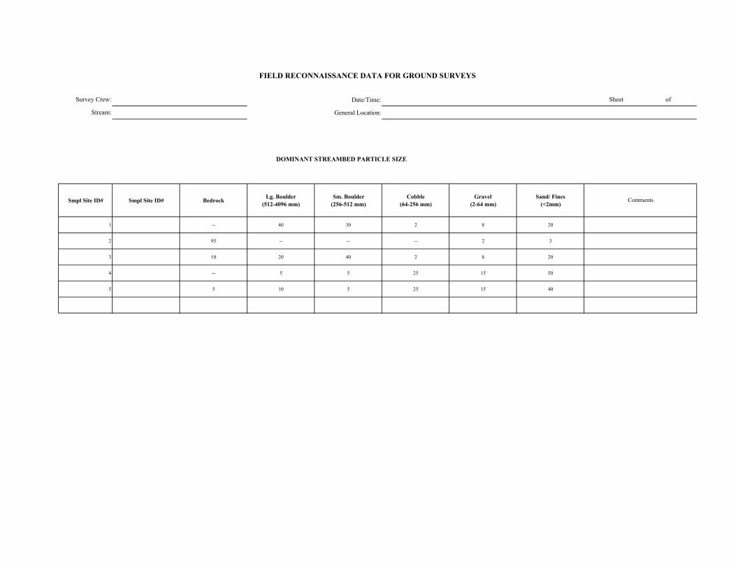
Date/Time:
General Location:
DOMINANT STREAMBED PARTICLE SIZE
Smpl Site ID# Smpl Site ID# Bedrock Lg. Boulder (512-4096 mm)
Sm. Boulder (256-512 mm)
Cobble (64-256 mm)
Gravel (2-64 mm)
Sand/ Fines (<2mm)
1 -- 40 30 2 8 20
2 95 -- -- -- 2 3
3 10 20 40 2 8 20
4 -- 5 5 25 15 50
5 5 10 5 25 15 40
FIELD RECONNAISSANCE DATA FOR GROUND SURVEYS
Sheet of
Comments
Survey Crew:
Stream:
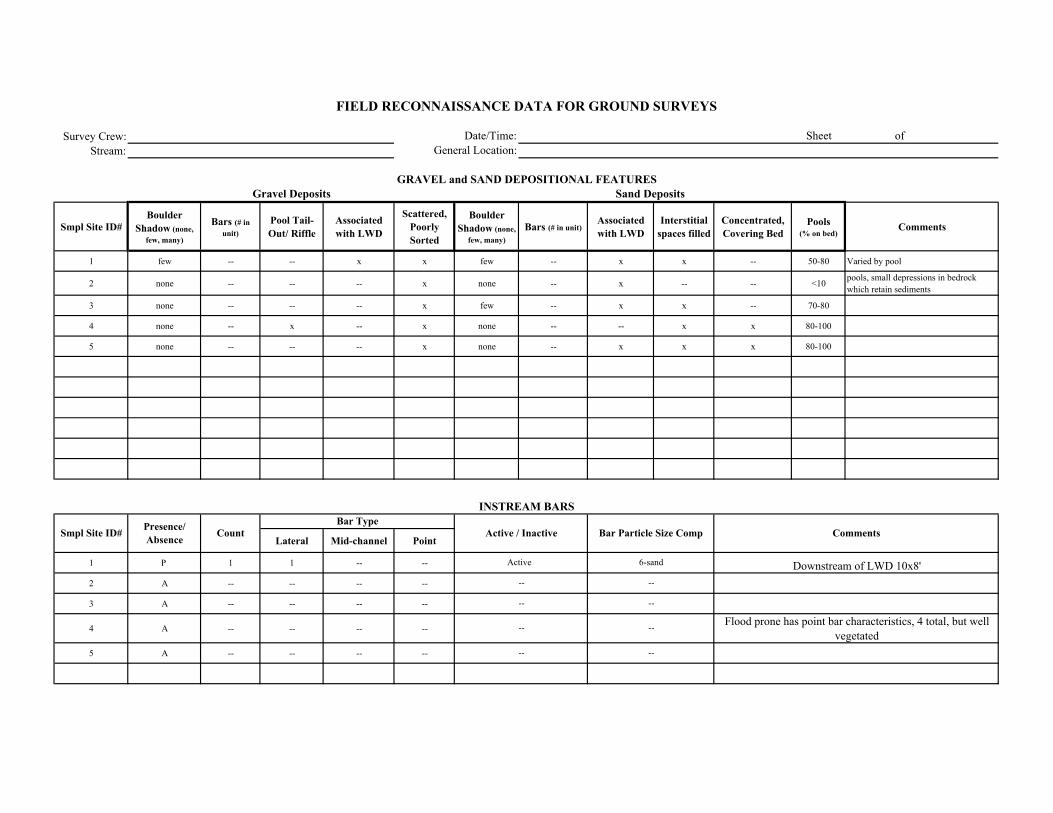
Survey Crew:Stream:
Smpl Site ID# Boulder
Shadow (none, few, many)
Bars (# in unit)
Pool Tail-Out/ Riffle
Associated with LWD
Scattered, Poorly Sorted
Boulder Shadow (none,
few, many)Bars (# in unit)
Associated with LWD
Interstitial spaces filled
Concentrated, Covering Bed
Pools (% on bed)
Comments
1 few -- -- x x few -- x x -- 50-80 Varied by pool
2 none -- -- -- x none -- x -- -- <10 pools, small depressions in bedrock which retain sediments
3 none -- -- -- x few -- x x -- 70-80
4 none -- x -- x none -- -- x x 80-100
5 none -- -- -- x none -- x x x 80-100
Lateral Mid-channel Point
1 P 1 1 -- --
2 A -- -- -- --
3 A -- -- -- --
4 A -- -- -- --
5 A -- -- -- --
Comments
Sand Deposits
INSTREAM BARS
Presence/ Absence Count Active / Inactive Bar Particle Size Comp
Bar Type
FIELD RECONNAISSANCE DATA FOR GROUND SURVEYS
Date/Time:General Location:
Sheet of
GRAVEL and SAND DEPOSITIONAL FEATURESGravel Deposits
Smpl Site ID#
Downstream of LWD 10x8'
Flood prone has point bar characteristics, 4 total, but well vegetated
6-sand
--
--
--
----
Active
--
--
--

Survey Crew: Date/Time: Sheet of
Stream: General Location:
Vegetation in Bankfull Channel
POSTION TYPE SIZE CLASS
1 A -- -- -- 1 --
2 A -- -- -- 1 --
3 A -- -- -- 1 --
4 A -- -- -- 1 --
5 A -- -- -- 1 -- Dense herb/willow/alder in flood prone area
Alder, ferns, willow, herb, along chanel margin above bankfull
Vegetation along banks above bankfull
Vegetation along banks above bankfull
Dense herb/willow/alder in flood prone area
Comments
VEGETATION ENCROACHMENT
FIELD RECONNAISSANCE DATA FOR GROUND SURVEYS
Smpl Site ID# VEG w/in BF
channel (P/A)
Vegetation Encroachment Rating
Veg Sz. Cl. in Relict BF Ch.
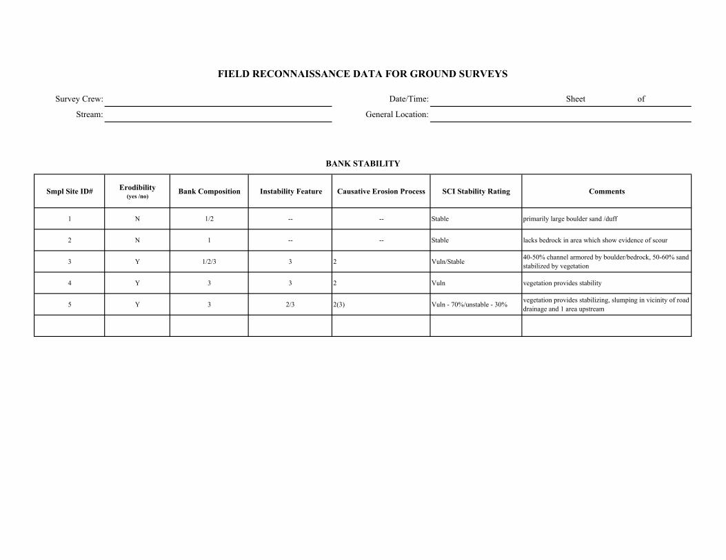
Survey Crew: Date/Time: Sheet of
Stream: General Location:
Smpl Site ID# Erodibility (yes /no)
Bank Composition Instability Feature Causative Erosion Process SCI Stability Rating Comments
1 N 1/2 -- -- Stable primarily large boulder sand /duff
2 N 1 -- -- Stable lacks bedrock in area which show evidence of scour
3 Y 1/2/3 3 2 Vuln/Stable 40-50% channel armored by boulder/bedrock, 50-60% sand stabilized by vegetation
4 Y 3 3 2 Vuln vegetation provides stability
5 Y 3 2/3 2(3) Vuln - 70%/unstable - 30% vegetation provides stabilizing, slumping in vicinity of road drainage and 1 area upstream
FIELD RECONNAISSANCE DATA FOR GROUND SURVEYS
BANK STABILITY

Survey Crew: Date/Time:
Stream: General Location:
Smpl Site ID# Upslope Streambank Size of Erosion / Deposition Feature
Dominant Particle Size
1 4 -- unit Sand/organic -6, some large/small boulder
2 4 -- unit 6
3 4 1 unit 6
4 -- 1/3 3 -20% of unit(50-100')/ 1-unit 6
5 4 1/2/3 2/3 30% of unit and 1/2 - 20% unit 6
Smpl Site ID# Deposition / No
Deposition Active/ Inactive Size of Deposition Dominant Particle Size
Sheet of
FIELD RECONNAISSANCE DATA FOR GROUND SURVEYS
Comments
Tributary Deposition
STREAM-SIDE SEDIMENT SOURCES
Comments
Upslope significant sand and organic material upslope with abundant duffUpslope significant sand and organic material upslope with abundant duff
Upslope with sand/organic streambank with some scour areas
100' section with slumping /unstable bank
30% of unit slumping especially downstream of road drainage
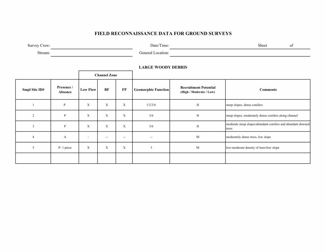
Survey Crew: Date/Time: Sheet of
Stream: General Location:
Smpl Site ID# Presence / Absence Low Flow BF FP Geomorphic Function Recruitment Potential
(High / Moderate / Low)Comments
1 P X X X 1/2/3/6 H steep slopes, dense conifers
2 P X X X 3/6 H steep slopes, moderately dense conifers along channel
3 P X X X 3/6 H moderate steep slopes/abundant conifers and abundant downed trees
4 A - -- -- -- M moderately dense trees, low slope
5 P- 1 piece X X X 3 M low-moderate density of trees/low slope
FIELD RECONNAISSANCE DATA FOR GROUND SURVEYS
LARGE WOODY DEBRIS
Channel Zone
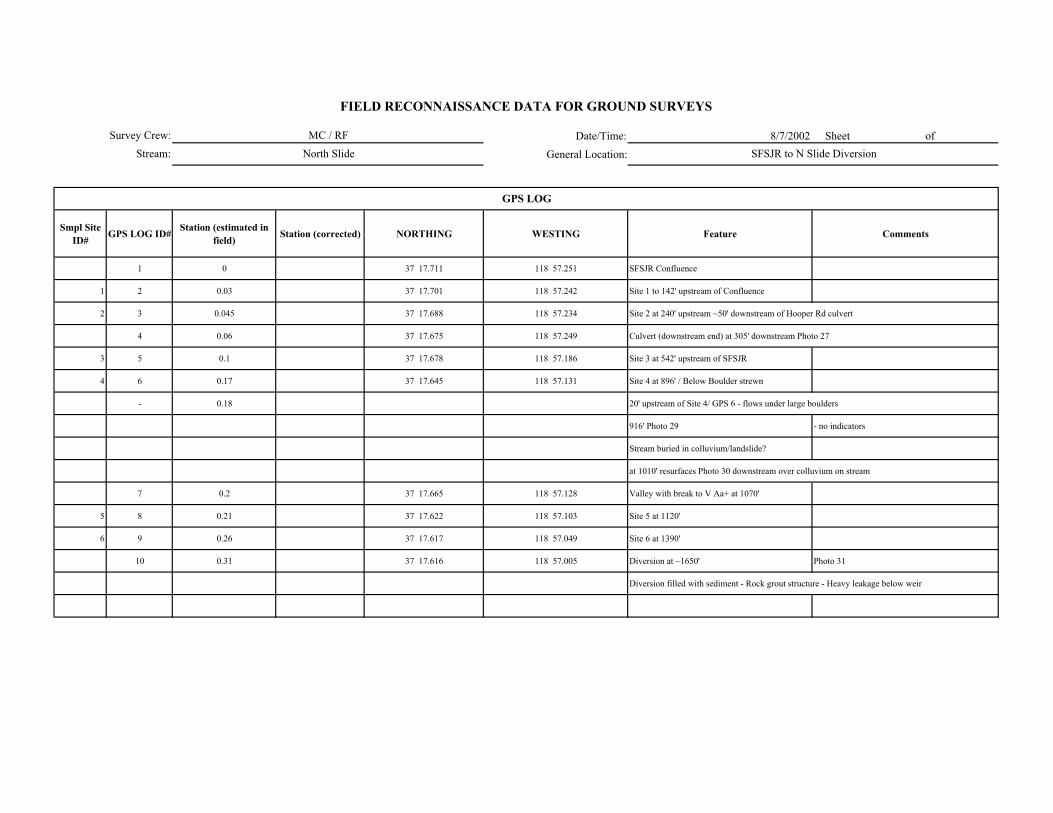
Date/Time: 8/7/2002 Sheet of
General Location:
Smpl Site ID# GPS LOG ID# Station (estimated in
field) Station (corrected) NORTHING WESTING Feature Comments
1 0 37 17.711 118 57.251 SFSJR Confluence
1 2 0.03 37 17.701 118 57.242 Site 1 to 142' upstream of Confluence
2 3 0.045 37 17.688 118 57.234 Site 2 at 240' upstream ~50' downstream of Hooper Rd culvert
4 0.06 37 17.675 118 57.249 Culvert (downstream end) at 305' downstream Photo 27
3 5 0.1 37 17.678 118 57.186 Site 3 at 542' upstream of SFSJR
4 6 0.17 37 17.645 118 57.131 Site 4 at 896' / Below Boulder strewn
- 0.18 20' upstream of Site 4/ GPS 6 - flows under large boulders
916' Photo 29 - no indicators
Stream buried in colluvium/landslide?
at 1010' resurfaces Photo 30 downstream over colluvium on stream
7 0.2 37 17.665 118 57.128 Valley with break to V Aa+ at 1070'
5 8 0.21 37 17.622 118 57.103 Site 5 at 1120'
6 9 0.26 37 17.617 118 57.049 Site 6 at 1390'
10 0.31 37 17.616 118 57.005 Diversion at ~1650' Photo 31
Diversion filled with sediment - Rock grout structure - Heavy leakage below weir
GPS LOG
Survey Crew:
Stream:
FIELD RECONNAISSANCE DATA FOR GROUND SURVEYS
MC / RF
North Slide SFSJR to N Slide Diversion

Survey Crew: Sheet of
Stream:
ER W/D Conf.
Station to Station Smpl Site ID#
WbfAve BF depth
(AveDbf)Max BF
depthWfp Wv Wfp /Wbf AveDbf /Wbf Wv /Wbf V U ( BF FP Wv
Bed-Form Montg.-Buffingt.
Stream Type Rosgen Comments GPS LOG
ID#
0.1 - 0.03 1 2.7 0.5 0.6 6.5 - 2.4 5.4 - X M M - 4 E5/A5a+ Steep near confluence ~5% to 140' upstream 2
0.03 - 0.04 2 3 0.6 0.8 5 - 1.67 5 - X M M - 3 B2/A2a+ Steep >10% 3
0.07 - 0.10 3 4 0.3 0.8 6.5 - 1.62 13.3 - X M M - 3 B2/A2a+ Steep >10% 5
0.15 - 0.17 4 3.5 0.4 0.6 10 2.5 8.7 - X M M - 4 E5/A5a+ spring like - shallow flow wide draw 6
0.20 - 0.22 5 3.5 0.4 0.6 4.5 30 1.29 8.7 8.6 X M M M 2(3) A3a+ mixed substrate High gradient 30%+ 8
0.22 - 0.26 6 2.3 0.5 0.7 4 20 1.74 4.6 8.7 X M M M A2a+ High Gradient 30%+ 9
FIELD RECONNAISSANCE DATA FOR GROUND SURVEYS
Degree of Confidence
CHANNEL ENTRENCHMENT, VALLEY CONFINEMENT, BED-FORM, and CHANNEL CLASSIFICATION
Valley Shape
Date/Time:
General Location:

Date/Time:
General Location:
DOMINANT STREAMBED PARTICLE SIZE
Smpl Site ID# GPS Smpl Site ID# Bedrock Lg. Boulder (512-4096 mm)
Sm. Boulder (256-512 mm)
Cobble (64-256 mm)
Gravel (2-64 mm)
Sand/ Fines (<2mm)
2 1 - 5 5 10 15 65
3 2 - 50 20 5 5 20
5 3 - 15 40 30 5 10
6 4 - 10 10 10 10 60
8 5 - 20 10 35 5 30
9 6 5 60 10 10 5 10
Survey Crew:
Stream:
Mixed
FIELD RECONNAISSANCE DATA FOR GROUND SURVEYS
Sheet of
Comments
Organic Material and Silt/Sand

Survey Crew:Stream:
Smpl Site ID# Boulder
Shadow (none, few, many)
Bars (# in unit)
Pool Tail-Out/ Riffle
Associated with LWD
Scattered, Poorly Sorted
Boulder Shadow (none,
few, many)Bars (# in unit)
Associated with LWD
Interstitial spaces filled
Concentrated, Covering Bed
Pools (% on bed)
Comments
1 none - - - Y many - Y Y Y 95 LWD is actually SWD
2 none - - - Y none - N Y N 50
3 none - - - - - - N Y N 30
4 none - - - Y few - Y Y Y 60
5 none - - - Y none - N Y N 45
6 none - - - Y none - N Y N 25
Lateral Mid-channel Point
1 A - - - -
2 A - - - -
3 A - - - -
4 A - - - -
5 A - - - -
6 A - - - -
-
-
-
-
-
-
-
-
-
-
-
-
FIELD RECONNAISSANCE DATA FOR GROUND SURVEYS
Date/Time:General Location:
Sheet of
GRAVEL and SAND DEPOSITIONAL FEATURESGravel Deposits
Smpl Site ID# Comments
Sand Deposits
INSTREAM BARS
Presence/ Absence Count Active / Inactive Bar Particle Size Comp
Bar Type

Survey Crew: Date/Time: Sheet of
Stream: General Location:
Vegetation in Bankfull Channel
POSTION TYPE SIZE CLASS
1 P 1 5 1 Possibly -
2 A - - - - -
3 A - - - - -
4 P 1/2 5 1 Possibly -
5 A - - - - -
6 A - - - - -
Comments
VEGETATION ENCROACHMENT
FIELD RECONNAISSANCE DATA FOR GROUND SURVEYS
Smpl Site ID# VEG w/in BF
channel (P/A)
Vegetation Encroachment Rating
Veg Sz. Cl. in Relict BF Ch.
grass at bankfull
some herbaceous at bankfull (spotty)
Alder rooting at bankfull indicator line
grasses/herbs at bankfull, aspen in relict channel
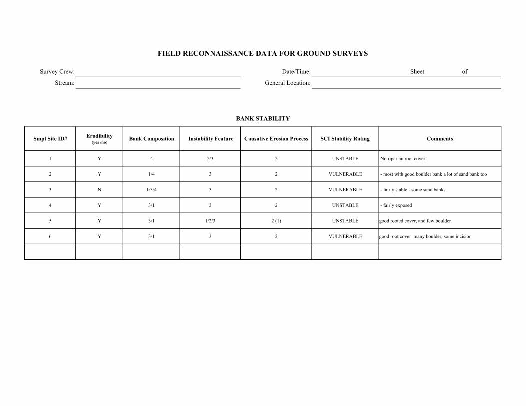
Survey Crew: Date/Time: Sheet of
Stream: General Location:
Smpl Site ID# Erodibility (yes /no)
Bank Composition Instability Feature Causative Erosion Process SCI Stability Rating Comments
1 Y 4 2/3 2 UNSTABLE No riparian root cover
2 Y 1/4 3 2 VULNERABLE - most with good boulder bank a lot of sand bank too
3 N 1/3/4 3 2 VULNERABLE - fairly stable - some sand banks
4 Y 3/1 3 2 UNSTABLE - fairly exposed
5 Y 3/1 1/2/3 2 (1) UNSTABLE good rooted cover, and few boulder
6 Y 3/1 3 2 VULNERABLE good root cover many boulder, some incision
FIELD RECONNAISSANCE DATA FOR GROUND SURVEYS
BANK STABILITY
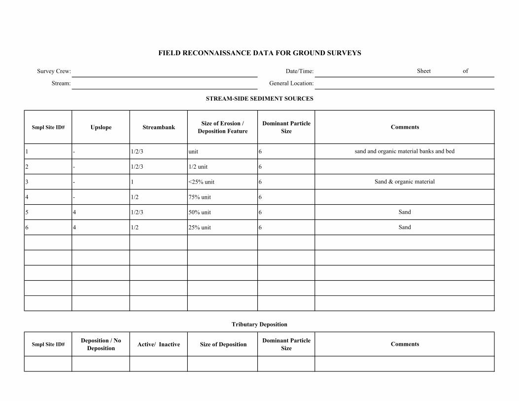
Survey Crew: Date/Time:
Stream: General Location:
Smpl Site ID# Upslope Streambank Size of Erosion / Deposition Feature
Dominant Particle Size
1 - 1/2/3 unit 6
2 - 1/2/3 1/2 unit 6
3 - 1 <25% unit 6
4 - 1/2 75% unit 6
5 4 1/2/3 50% unit 6
6 4 1/2 25% unit 6
Smpl Site ID# Deposition / No
Deposition Active/ Inactive Size of Deposition Dominant Particle Size
Sand
Sand
Sheet of
FIELD RECONNAISSANCE DATA FOR GROUND SURVEYS
Comments
Tributary Deposition
STREAM-SIDE SEDIMENT SOURCES
Comments
sand and organic material banks and bed
Sand & organic material
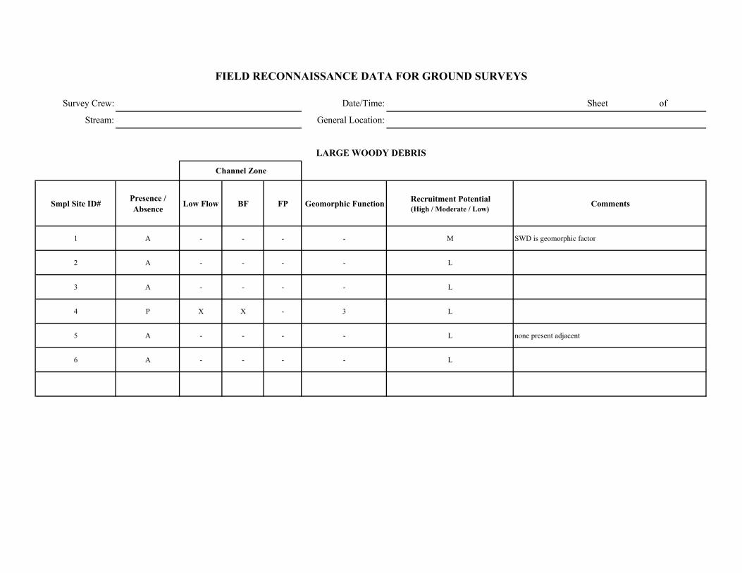
Survey Crew: Date/Time: Sheet of
Stream: General Location:
Smpl Site ID# Presence / Absence Low Flow BF FP Geomorphic Function Recruitment Potential
(High / Moderate / Low)Comments
1 A - - - - M SWD is geomorphic factor
2 A - - - - L
3 A - - - - L
4 P X X - 3 L
5 A - - - - L none present adjacent
6 A - - - - L
FIELD RECONNAISSANCE DATA FOR GROUND SURVEYS
LARGE WOODY DEBRIS
Channel Zone
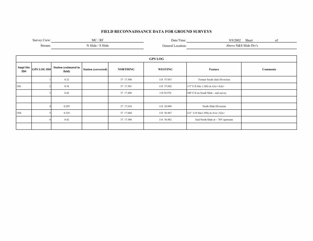
Date/Time: 9/9/2002 Sheet of
General Location:
Smpl Site ID# GPS LOG ID# Station (estimated in
field) Station (corrected) NORTHING WESTING Feature Comments
1 0.32 37 17.508 118 57.053 Former South slide Diversion
1SS 2 0.34 37 17.501 118 57.042 117' U/S Site 1 (SS) in A1a+/A2a+
3 0.42 37 17.496 118 56.976 540' U/S on South Slide - end survey
4 0.285 37 17.618 118 56.004 North Slide Diversion
1NS 5 0.325 37 17.604 118 56.967 212' U/S Site1 (NS) in A1a+/A2a+
6 0.42 37 17.580 118 56.882 End North Slide at ~ 705' upstream
GPS LOG
Survey Crew:
Stream:
FIELD RECONNAISSANCE DATA FOR GROUND SURVEYS
MC / RF
N Slide / S Slide Above N&S Slide Div's
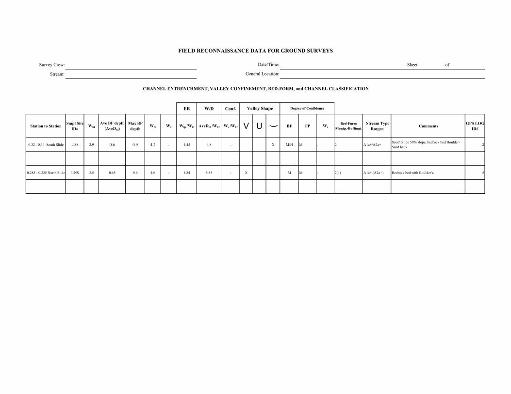
Survey Crew: Sheet of
Stream:
ER W/D Conf.
Station to Station Smpl Site ID#
WbfAve BF depth
(AveDbf)Max BF
depthWfp Wv Wfp /Wbf AveDbf /Wbf Wv /Wbf V U ( BF FP Wv
Bed-Form Montg.-Buffingt.
Stream Type Rosgen Comments GPS LOG
ID#
0.32 - 0.34 South Slide 1-SS 2.9 0.6 0.9 4.2 - 1.45 4.8 - X M/H M - 2 A1a+/A2a+South Slide 50% slope, bedrock bed/Boulder-Sand bank 2
0.285 - 0.325 North Slide 1-NS 2.5 0.45 0.6 4.6 - 1.84 5.55 - X M M - 2(1) A1a+ (A2a+) Bedrock bed with Boulder's. 5
FIELD RECONNAISSANCE DATA FOR GROUND SURVEYS
Degree of Confidence
CHANNEL ENTRENCHMENT, VALLEY CONFINEMENT, BED-FORM, and CHANNEL CLASSIFICATION
Valley Shape
Date/Time:
General Location:
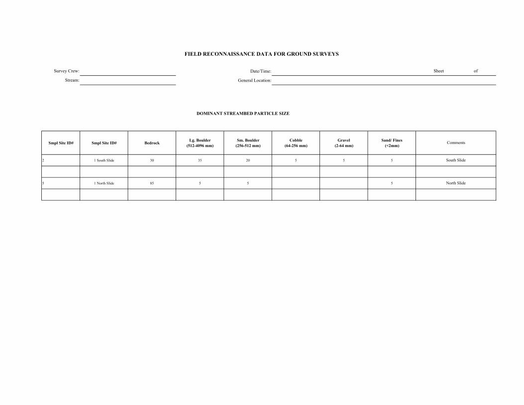
Date/Time:
General Location:
DOMINANT STREAMBED PARTICLE SIZE
Smpl Site ID# Smpl Site ID# Bedrock Lg. Boulder (512-4096 mm)
Sm. Boulder (256-512 mm)
Cobble (64-256 mm)
Gravel (2-64 mm)
Sand/ Fines (<2mm)
2 1 South Slide 30 35 20 5 5 5
5 1 North Slide 85 5 5 5
FIELD RECONNAISSANCE DATA FOR GROUND SURVEYS
Sheet of
Comments
South Slide
North Slide
Survey Crew:
Stream:
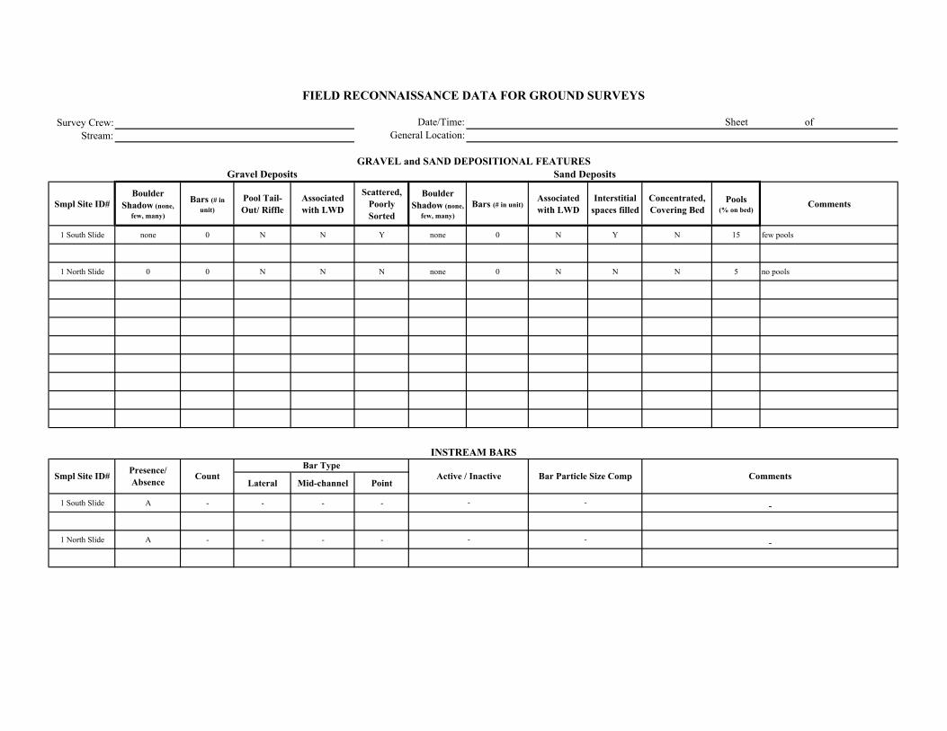
Survey Crew:Stream:
Smpl Site ID# Boulder
Shadow (none, few, many)
Bars (# in unit)
Pool Tail-Out/ Riffle
Associated with LWD
Scattered, Poorly Sorted
Boulder Shadow (none,
few, many)Bars (# in unit)
Associated with LWD
Interstitial spaces filled
Concentrated, Covering Bed
Pools (% on bed)
Comments
1 South Slide none 0 N N Y none 0 N Y N 15 few pools
1 North Slide 0 0 N N N none 0 N N N 5 no pools
Lateral Mid-channel Point
1 South Slide A - - - -
1 North Slide A - - - -
Comments
Sand Deposits
INSTREAM BARS
Presence/ Absence Count Active / Inactive Bar Particle Size Comp
Bar Type
FIELD RECONNAISSANCE DATA FOR GROUND SURVEYS
Date/Time:General Location:
Sheet of
GRAVEL and SAND DEPOSITIONAL FEATURESGravel Deposits
Smpl Site ID#
-
-
-
-
-
-
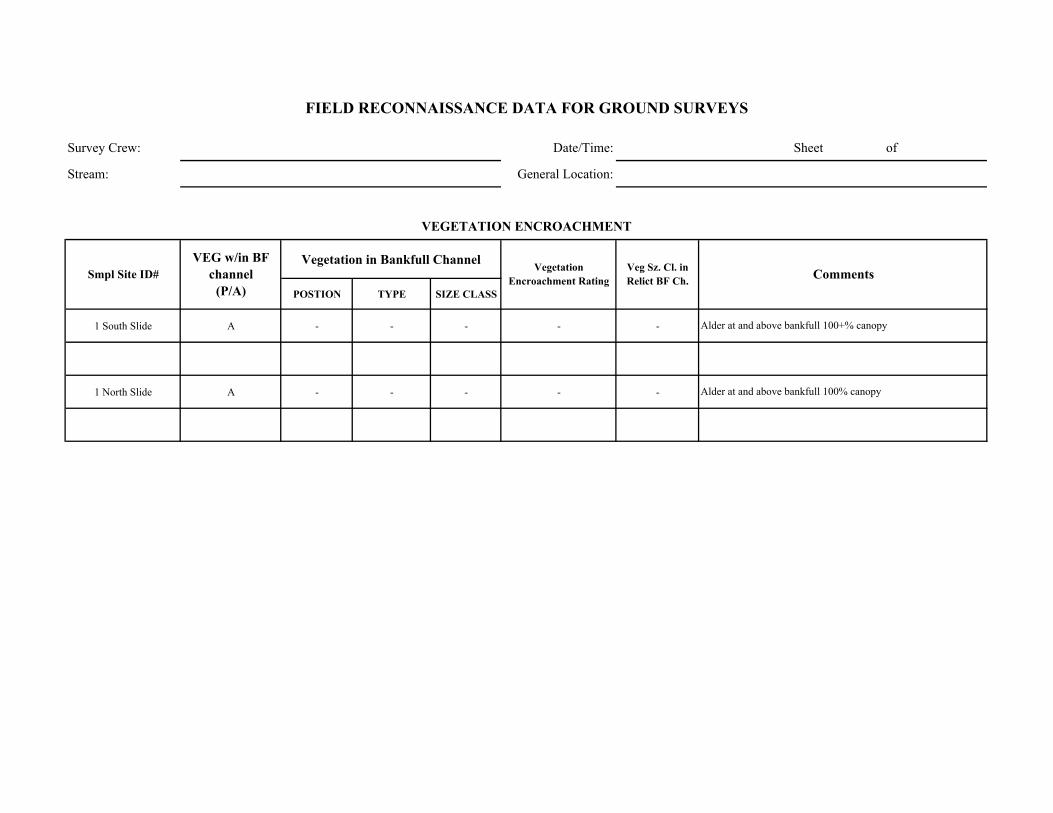
Survey Crew: Date/Time: Sheet of
Stream: General Location:
Vegetation in Bankfull Channel
POSTION TYPE SIZE CLASS
1 South Slide A - - - - -
1 North Slide A - - - - -
Alder at and above bankfull 100+% canopy
Alder at and above bankfull 100% canopy
Comments
VEGETATION ENCROACHMENT
FIELD RECONNAISSANCE DATA FOR GROUND SURVEYS
Smpl Site ID# VEG w/in BF
channel (P/A)
Vegetation Encroachment Rating
Veg Sz. Cl. in Relict BF Ch.

Survey Crew: Date/Time: Sheet of
Stream: General Location:
Smpl Site ID# Erodibility (yes /no)
Bank Composition Instability Feature Causative Erosion Process SCI Stability Rating Comments
1 South slide N 1 0(3) 2 (if any) stable few sand banks - good boulder/alder root cover.
1 North Slide N 1(3) 0(3) 2/1 stable (vulnerable) few undercuts, but mostly bedrock
FIELD RECONNAISSANCE DATA FOR GROUND SURVEYS
BANK STABILITY

Survey Crew: Date/Time:
Stream: General Location:
Smpl Site ID# Upslope Streambank Size of Erosion / Deposition Feature
Dominant Particle Size
1 South Slide 0 1 (2?) <5% unit sand
1 North Slide 4 1/2 10% unit sand
Smpl Site ID# Deposition / No
Deposition Active/ Inactive Size of Deposition Dominant Particle Size
Sheet of
FIELD RECONNAISSANCE DATA FOR GROUND SURVEYS
Comments
Tributary Deposition
STREAM-SIDE SEDIMENT SOURCES
Comments
few exposed sand banks in good boulder/alder cover
few exposed bank areas - most bedrock/boulder with alder cover
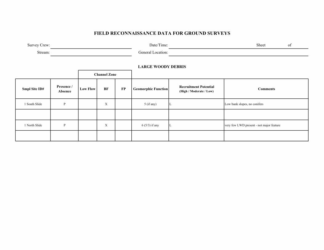
Survey Crew: Date/Time: Sheet of
Stream: General Location:
Smpl Site ID# Presence / Absence Low Flow BF FP Geomorphic Function Recruitment Potential
(High / Moderate / Low)Comments
1 South Slide P X 5 (if any) L Low bank slopes, no conifers
1 North Slide P X 6 (5/3) if any L very few LWD present - not major feature
FIELD RECONNAISSANCE DATA FOR GROUND SURVEYS
LARGE WOODY DEBRIS
Channel Zone
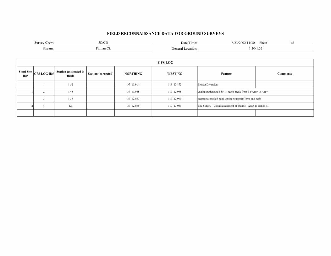
Date/Time: 8/23/2002 11:30 Sheet of
General Location:
Smpl Site ID# GPS LOG ID# Station (estimated in
field) Station (corrected) NORTHING WESTING Feature Comments
1 1.52 37 11.914 119 12.873 Pitman Diversion
1 2 1.43 37 11.968 119 12.938 gaging station and SS# 1 , reach break from B1/A1a+ to A1a+
3 1.38 37 12.050 119 12.990 seepage along left bank upslope supports ferns and herb.
2 4 1.3 37 12.035 119 13.081 End Survey - Visual assessment of channel- A1a+ to station 1.1
GPS LOG
Survey Crew:
Stream:
FIELD RECONNAISSANCE DATA FOR GROUND SURVEYS
JC/CB
Pitman Ck 1.10-1.52

Survey Crew: Sheet of
Stream:
ER W/D Conf.
Station to Station Smpl Site ID#
WbfAve BF depth
(AveDbf)Max BF
depthWfp Wv Wfp /Wbf AveDbf /Wbf Wv /Wbf V U ( BF FP Wv
Bed-Form Montg.-Buffingt.
Stream Type
RosgenComments GPS LOG
ID#
1.43-1.52 1 75' -- -- -- 150 -- -- -- x -- -- -- 1/3 B1/A1a+Bedrock channel no apparent bankfull indicators, Sheet flow/pools 2
1.30-1.35 2 80' -- -- -- 500 -- -- -- x -- -- -- 1/2 A1a+Bedrock cascade with kettle pools and scour pools at base of cascades 4
FIELD RECONNAISSANCE DATA FOR GROUND SURVEYS
Degree of Confidence
CHANNEL ENTRENCHMENT, VALLEY CONFINEMENT, BED-FORM, and CHANNEL CLASSIFICATION
Valley Shape
Date/Time:
General Location:

Date/Time:
General Location:
DOMINANT STREAMBED PARTICLE SIZE
Smpl Site ID# Smpl Site ID# Bedrock Lg. Boulder (512-4096 mm)
Sm. Boulder (256-512 mm)
Cobble (64-256 mm)
Gravel (2-64 mm)
Sand/ Fines (<2mm)
1 90 8
2 95 3 --------------------2%-----------------
-----------------2%-----------------
FIELD RECONNAISSANCE DATA FOR GROUND SURVEYS
Sheet of
Comments
Survey Crew:
Stream:
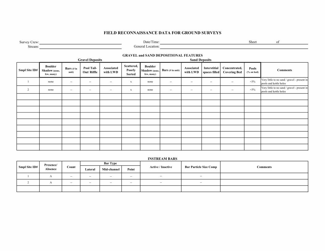
Survey Crew:Stream:
Smpl Site ID# Boulder
Shadow (none, few, many)
Bars (# in unit)
Pool Tail-Out/ Riffle
Associated with LWD
Scattered, Poorly Sorted
Boulder Shadow (none,
few, many)Bars (# in unit)
Associated with LWD
Interstitial spaces filled
Concentrated, Covering Bed
Pools (% on bed)
Comments
1 none -- -- -- x none -- -- -- -- <5% Very little to no sand / gravel - present in pools and kettle holes
2 none -- -- -- x none -- -- -- -- <5% Very little to no sand / gravel - present in pools and kettle holes
Lateral Mid-channel Point
1 A -- -- -- --
2 A -- -- -- --
Comments
Sand Deposits
INSTREAM BARS
Presence/ Absence Count Active / Inactive Bar Particle Size Comp
Bar Type
FIELD RECONNAISSANCE DATA FOR GROUND SURVEYS
Date/Time:General Location:
Sheet of
GRAVEL and SAND DEPOSITIONAL FEATURESGravel Deposits
Smpl Site ID#
--
--
--
--

Survey Crew: Date/Time: Sheet of
Stream: General Location:
Vegetation in Bankfull Channel
POSTION TYPE SIZE CLASS
1 A/P? 3? 3/5? 1? 1/2 --
2 A -- -- -- 1 --
-No apparent BF indicators within top width of channel
Comments
VEGETATION ENCROACHMENT
FIELD RECONNAISSANCE DATA FOR GROUND SURVEYS
Smpl Site ID# VEG w/in BF
channel (P/A)
Vegetation Encroachment Rating
Veg Sz. Cl. in Relict BF Ch.

Survey Crew: Date/Time: Sheet of
Stream: General Location:
Smpl Site ID# Erodibility (yes /no)
Bank Composition Instability Feature Causative Erosion Process SCI Stability Rating Comments
1 N 1 0 -- Stable
2 N 1 0 -- Stable
FIELD RECONNAISSANCE DATA FOR GROUND SURVEYS
BANK STABILITY
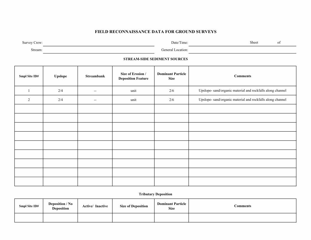
Survey Crew: Date/Time:
Stream: General Location:
Smpl Site ID# Upslope Streambank Size of Erosion / Deposition Feature
Dominant Particle Size
1 2/4 -- unit 2/6
2 2/4 -- unit 2/6
Smpl Site ID# Deposition / No
Deposition Active/ Inactive Size of Deposition Dominant Particle Size
Sheet of
FIELD RECONNAISSANCE DATA FOR GROUND SURVEYS
Comments
Tributary Deposition
STREAM-SIDE SEDIMENT SOURCES
Comments
Upslope- sand/organic material and rockfalls along channel
Upslope- sand/organic material and rockfalls along channel

Survey Crew: Date/Time: Sheet of
Stream: General Location:
Smpl Site ID# Presence / Absence Low Flow BF FP Geomorphic Function Recruitment Potential
(High / Moderate / Low)Comments
1 A -- -- -- -- H Dense conifers along channel and steep slopes
2 A -- -- -- -- H Dense conifers along channel and steep slopes
FIELD RECONNAISSANCE DATA FOR GROUND SURVEYS
LARGE WOODY DEBRIS
Channel Zone
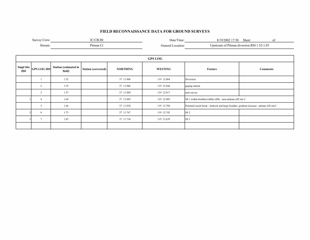
Date/Time: 8/19/2002 17:30 Sheet of
General Location:
Smpl Site ID# GPS LOG ID# Station (estimated in
field) Station (corrected) NORTHING WESTING Feature Comments
1 1.52 37 11.906 119 12.864 Diversion
2 1.55 37 11.906 119 12.844 gaging station
3 1.57 37 11.909 119 12.817 start survey
1 4 1.64 37 11.845 119 12.805 SS 1 within boulder/cobble riffle - near pitman AD site 2
5 1.66 37 11.838 119 12.788 Potential reach break - bedrock and large boulder- gradient increase - pitman AD site3
2 6 1.75 37 11.767 119 12.742 SS 2
3 7 1.85 37 11.734 119 12.639 SS 3
GPS LOG
Survey Crew:
Stream:
FIELD RECONNAISSANCE DATA FOR GROUND SURVEYS
JC/CB/JH
Pitman Cr Upstream of Pitman diversion RM 1.52-1.85
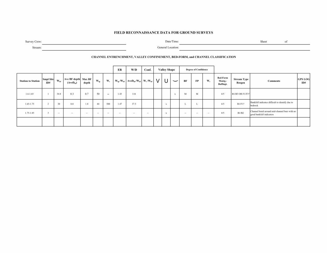
Survey Crew: Sheet of
Stream:
ER W/D Conf.
Station to Station Smpl Site ID#
WbfAve BF depth
(AveDbf)Max BF
depthWfp Wv Wfp /Wbf AveDbf /Wbf Wv /Wbf V U ( BF FP Wv
Bed-Form Montg.-Buffingt.
Stream Type Rosgen Comments GPS LOG
ID#
1.6-1.65 1 34.8 0.3 0.7 50 -- 1.43 116 x M M 4/5 B1/B3 OR F1/F3?
1.65-1.75 2 30 0.8 1.8 44 500 1.47 37.5 x L L 4/5 B1/F1?Bankfull indicates difficult to identify due to bedrock
1.75-1.85 3 -- -- -- -- -- -- -- -- x -- -- -- 4/5 B1/B2Channel braid around mid-channel bars with no good bankfull indicators
FIELD RECONNAISSANCE DATA FOR GROUND SURVEYS
Degree of Confidence
CHANNEL ENTRENCHMENT, VALLEY CONFINEMENT, BED-FORM, and CHANNEL CLASSIFICATION
Valley Shape
Date/Time:
General Location:

Date/Time:
General Location:
DOMINANT STREAMBED PARTICLE SIZE
Smpl Site ID# Smpl Site ID# Bedrock Lg. Boulder (512-4096 mm)
Sm. Boulder (256-512 mm)
Cobble (64-256 mm)
Gravel (2-64 mm)
Sand/ Fines (<2mm)
1 30 10 10 25 20 5
2 70 10 -- 5 5 10
3 30 40 -- 20 5 5
FIELD RECONNAISSANCE DATA FOR GROUND SURVEYS
Sheet of
Comments
Survey Crew:
Stream:

Survey Crew:Stream:
Smpl Site ID# Boulder
Shadow (none, few, many)
Bars (# in unit)Pool Tail-Out/ Riffle
Associated with LWD
Scattered, Poorly Sorted
Boulder Shadow (none,
few, many)Bars (# in unit)
Associated with LWD
Interstitial spaces filled
Concentrated, Covering Bed
Pools (% on bed)
Comments
1 few 2 -- -- x few -- -- x -- 50
2 many x -- -- x many 2 -- x -- 80
3 few -- -- x x few -- x x -- 40
Lateral Mid-channel Point
1 P 2 1 -- 1
2 P 4 3 1 --
3 P 3 1 2 --
Comments
Sand Deposits
INSTREAM BARS
Presence/ Absence Count Active / Inactive Bar Particle Size Comp
Bar Type
FIELD RECONNAISSANCE DATA FOR GROUND SURVEYS
Date/Time:General Location:
Sheet of
GRAVEL and SAND DEPOSITIONAL FEATURESGravel Deposits
Smpl Site ID#
1 mid-channel bar of boulder - lateral bars occur in boulder shadows
cobble
laterals- 2 sand - 1 cobble
lateral cobble mid-channel bar- boulder
A
A
A
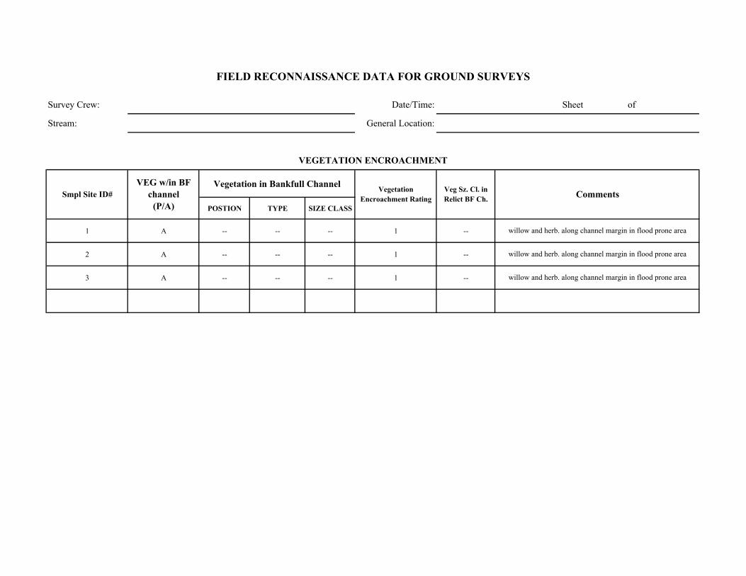
Survey Crew: Date/Time: Sheet of
Stream: General Location:
Vegetation in Bankfull Channel
POSTION TYPE SIZE CLASS
1 A -- -- -- 1 --
2 A -- -- -- 1 --
3 A -- -- -- 1 --
willow and herb. along channel margin in flood prone area
willow and herb. along channel margin in flood prone area
willow and herb. along channel margin in flood prone area
Comments
VEGETATION ENCROACHMENT
FIELD RECONNAISSANCE DATA FOR GROUND SURVEYS
Smpl Site ID# VEG w/in BF
channel (P/A)
Vegetation Encroachment Rating
Veg Sz. Cl. in Relict BF Ch.
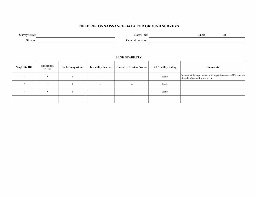
Survey Crew: Date/Time: Sheet of
Stream: General Location:
Smpl Site ID# Erodibility (yes /no)
Bank Composition Instability Feature Causative Erosion Process SCI Stability Rating Comments
1 N 1 -- -- Stable Predominately large boulder with vegetation cover-~20% consists of sand /cobble with some scour
2 N 1 -- -- Stable
3 N 1 -- -- Stable
FIELD RECONNAISSANCE DATA FOR GROUND SURVEYS
BANK STABILITY

Survey Crew: Date/Time:
Stream: General Location:
Smpl Site ID# Upslope Streambank Size of Erosion / Deposition Feature
Dominant Particle Size
1 -- 1 ~20% unit 6
2 2/4 -- unit 2/3/6
3 2/4 -- unit 2/3/6
Smpl Site ID# Deposition / No
Deposition Active/ Inactive Size of Deposition Dominant Particle Size
Sheet of
FIELD RECONNAISSANCE DATA FOR GROUND SURVEYS
Comments
Tributary Deposition
STREAM-SIDE SEDIMENT SOURCES
Comments
20% of banks consist of sand / cobble which show some scour
Rock falls and sand/organic material from upslope
Rock falls and sand/organic material from upslope
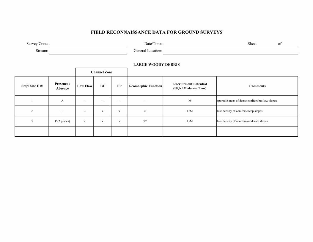
Survey Crew: Date/Time: Sheet of
Stream: General Location:
Smpl Site ID# Presence / Absence Low Flow BF FP Geomorphic Function Recruitment Potential
(High / Moderate / Low)Comments
1 A -- -- -- -- M sporadic areas of dense conifers but low slopes
2 P -- x x 6 L/M low density of conifers/steep slopes
3 P (2 places) x x x 3/6 L/M low density of conifers/moderate slopes
FIELD RECONNAISSANCE DATA FOR GROUND SURVEYS
LARGE WOODY DEBRIS
Channel Zone
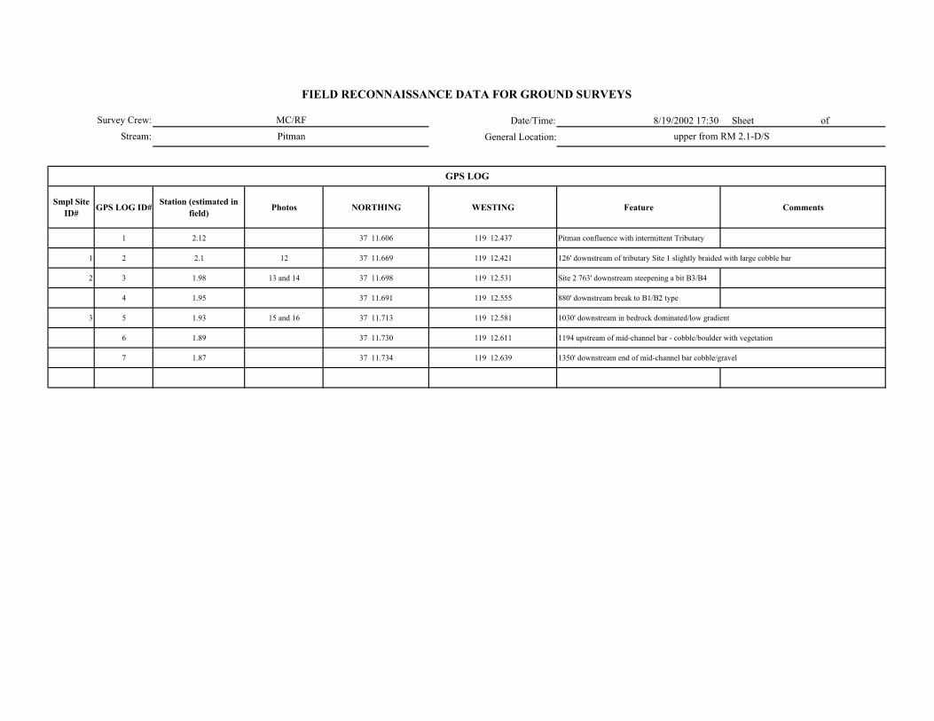
Date/Time: 8/19/2002 17:30 Sheet of
General Location:
Smpl Site ID# GPS LOG ID# Station (estimated in
field) Photos NORTHING WESTING Feature Comments
1 2.12 37 11.606 119 12.437 Pitman confluence with intermittent Tributary
1 2 2.1 12 37 11.669 119 12.421 126' downstream of tributary Site 1 slightly braided with large cobble bar
2 3 1.98 13 and 14 37 11.698 119 12.531 Site 2 763' downstream steepening a bit B3/B4
4 1.95 37 11.691 119 12.555 880' downstream break to B1/B2 type
3 5 1.93 15 and 16 37 11.713 119 12.581 1030' downstream in bedrock dominated/low gradient
6 1.89 37 11.730 119 12.611 1194 upstream of mid-channel bar - cobble/boulder with vegetation
7 1.87 37 11.734 119 12.639 1350' downstream end of mid-channel bar cobble/gravel
GPS LOG
Survey Crew:
Stream:
FIELD RECONNAISSANCE DATA FOR GROUND SURVEYS
MC/RF
Pitman upper from RM 2.1-D/S
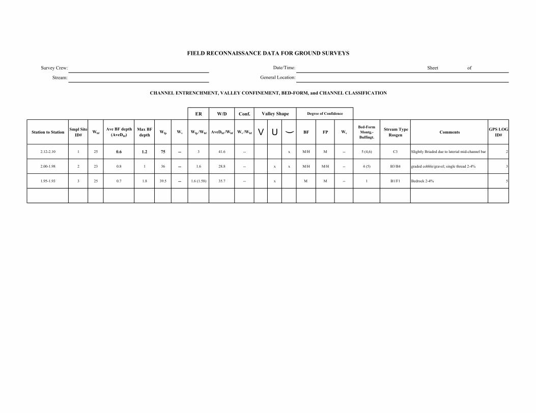
Survey Crew: Sheet of
Stream:
ER W/D Conf.
Station to Station Smpl Site ID#
WbfAve BF depth
(AveDbf)Max BF
depthWfp Wv Wfp /Wbf AveDbf /Wbf Wv /Wbf V U ( BF FP Wv
Bed-Form Montg.-Buffingt.
Stream Type Rosgen Comments GPS LOG
ID#
2.12-2.10 1 25 0.6 1.2 75 -- 3 41.6 -- x M/H M -- 5 (4,6) C3 SIightly Briaded due to laterial mid-channel bar 2
2.00-1.98 2 23 0.8 1 36 -- 1.6 28.8 -- x x M/H M/H -- 4 (5) B3/B4 graded cobble/gravel; single thread 2-4% 3
1.95-1.93 3 25 0.7 1.8 39.5 -- 1.6 (1.58) 35.7 -- x M M -- 1 B1/F1 Bedrock 2-4% 5
FIELD RECONNAISSANCE DATA FOR GROUND SURVEYS
Degree of Confidence
CHANNEL ENTRENCHMENT, VALLEY CONFINEMENT, BED-FORM, and CHANNEL CLASSIFICATION
Valley Shape
Date/Time:
General Location:

Date/Time:
General Location:
DOMINANT STREAMBED PARTICLE SIZE
Smpl Site ID# Smpl Site ID# Bedrock Lg. Boulder (512-4096 mm)
Sm. Boulder (256-512 mm)
Cobble (64-256 mm)
Gravel (2-64 mm)
Sand/ Fines (<2mm)
2 1 -- 5 10 55 15 15
3 2 10 10 5 35 35 5
5 3 90 2.5 2.5 -- 2.5 2.5
FIELD RECONNAISSANCE DATA FOR GROUND SURVEYS
Sheet of
Comments
Survey Crew:
Stream:
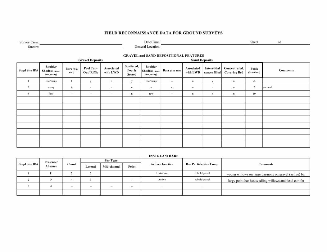
Survey Crew:Stream:
Smpl Site ID# Boulder
Shadow (none, few, many)
Bars (# in unit)
Pool Tail-Out/ Riffle
Associated with LWD
Scattered, Poorly Sorted
Boulder Shadow (none,
few, many)Bars (# in unit)
Associated with LWD
Interstitial spaces filled
Concentrated, Covering Bed
Pools (% on bed)
Comments
1 few/many 1 y n y few/many -- n y n 75
2 many 4 n n n n n n n n 2 no sand
3 few -- -- -- n few -- n n n 10
Lateral Mid-channel Point
1 P 2 2
2 P 4 3 1
3 A -- -- -- --
cobble/gravel
--
Comments
Sand Deposits
INSTREAM BARS
Presence/ Absence Count Active / Inactive Bar Particle Size Comp
Bar Type
FIELD RECONNAISSANCE DATA FOR GROUND SURVEYS
Date/Time:General Location:
Sheet of
GRAVEL and SAND DEPOSITIONAL FEATURESGravel Deposits
Smpl Site ID#
young willows on large bar/none on gravel (active) bar
large point bar has seedling willows and dead conifercobble/gravel
Unknown
Active
--
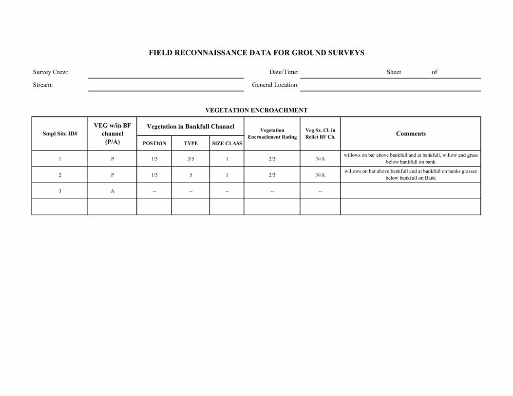
Survey Crew: Date/Time: Sheet of
Stream: General Location:
Vegetation in Bankfull Channel
POSTION TYPE SIZE CLASS
1 P 1/3 3/5 1 2/3 N/A
2 P 1/3 5 1 2/3 N/A
3 A -- -- -- -- --
willows on bar above bankfull and at bankfull, willow and grass below bankfull on bank
willows on bar above bankfull and at bankfull on banks grasses below bankfull on Bank
Comments
VEGETATION ENCROACHMENT
FIELD RECONNAISSANCE DATA FOR GROUND SURVEYS
Smpl Site ID# VEG w/in BF
channel (P/A)
Vegetation Encroachment Rating
Veg Sz. Cl. in Relict BF Ch.
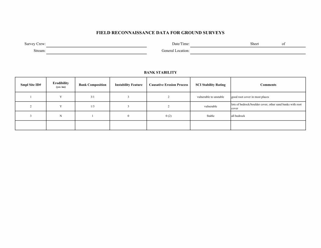
Survey Crew: Date/Time: Sheet of
Stream: General Location:
Smpl Site ID# Erodibility (yes /no)
Bank Composition Instability Feature Causative Erosion Process SCI Stability Rating Comments
1 Y 3/1 3 2 vulnerable to unstable good root cover in most places
2 Y 1/3 3 2 vulnerable lots of bedrock/boulder cover, other sand banks with root cover
3 N 1 0 0 (2) Stable all bedrock
FIELD RECONNAISSANCE DATA FOR GROUND SURVEYS
BANK STABILITY
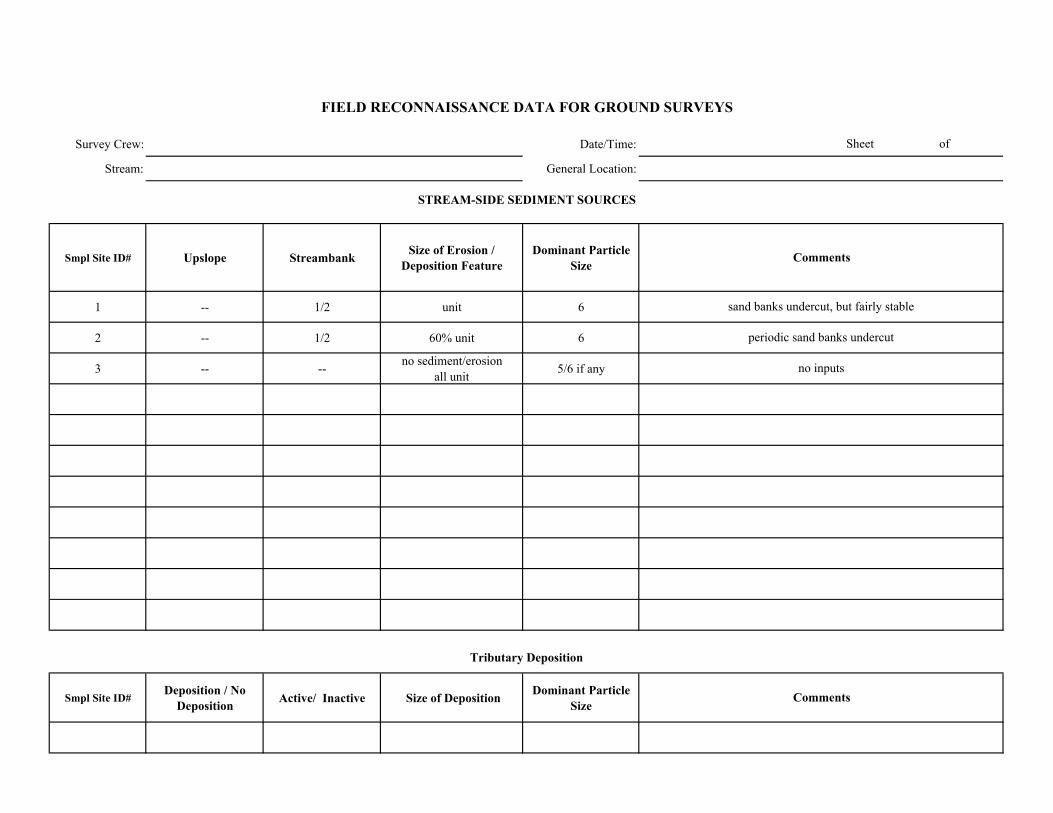
Survey Crew: Date/Time:
Stream: General Location:
Smpl Site ID# Upslope Streambank Size of Erosion / Deposition Feature
Dominant Particle Size
1 -- 1/2 unit 6
2 -- 1/2 60% unit 6
3 -- -- no sediment/erosion all unit 5/6 if any
Smpl Site ID# Deposition / No
Deposition Active/ Inactive Size of Deposition Dominant Particle Size
Sheet of
FIELD RECONNAISSANCE DATA FOR GROUND SURVEYS
Comments
Tributary Deposition
STREAM-SIDE SEDIMENT SOURCES
Comments
sand banks undercut, but fairly stable
periodic sand banks undercut
no inputs
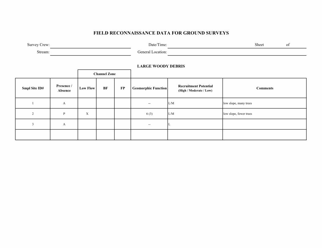
Survey Crew: Date/Time: Sheet of
Stream: General Location:
Smpl Site ID# Presence / Absence Low Flow BF FP Geomorphic Function Recruitment Potential
(High / Moderate / Low)Comments
1 A -- L/M low slope, many trees
2 P X 6 (3) L/M low slope, fewer trees
3 A -- L
FIELD RECONNAISSANCE DATA FOR GROUND SURVEYS
LARGE WOODY DEBRIS
Channel Zone

Date/Time: 9/10/2002 8:45 Sheet of General Location:
Smpl Site ID# GPS LOG ID# Station (estimated in
field) Station (corrected) NORTHING WESTING Feature Comments
1 0.48 37 16.482 119 20.383 Rock Creek --> diversion
1 2 0.38 37 16.469 119 20.304 Downstream of Survey 2' diameter pipe, daylights along right bank and goes into bedrock Tunnel
3 0.5 37 16.507 119 20.408 Upstream end of impound --> start survey segment
4 0.6 37 16.516 119 20.464 End of survey segment (.5-.6)
3 5 0.67 37 16.519 119 20.533 break to A1a+ approximately 150' upstream of measure point --> at 100' bedrock Fall
2 6 0.52 37 16.487 119 20.389 SS #2
GPS LOG
Survey Crew:Stream:
FIELD RECONNAISSANCE DATA FOR GROUND SURVEYS
JC/CBRock Creek Station 0.4 - 0.7
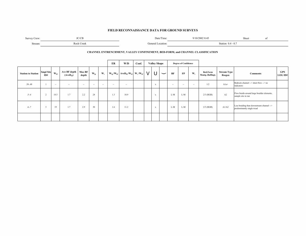
Survey Crew: Sheet of
Stream:
ER W/D Conf.
Station to Station Smpl Site ID#
WbfAve BF depth
(AveDbf)Max BF
depthWfp Wv Wfp /Wbf AveDbf /Wbf Wv /Wbf V U ( BF FP Wv
Bed-Form Montg.-Buffingt.
Stream Type Rosgen Comments GPS
LOG ID#
.38-.48 1 -- -- -- -- -- -- -- x -- -- -- 1/2 A1a+ Bedrock channel --> sheet flow --> no indicators
.5-.6 2 18.5 1.7 2.2 24 1.3 10.9 x L-M L-M 2/3 (HGR) A2 Flow braids around large boulder elements, sample site in run
.6-.7 3 19 1.7 2.9 30 1.6 11.2 x L-M L-M 2/3 (HGR) A1/A2 Less braiding than downstream channel --> predominantly single tread
FIELD RECONNAISSANCE DATA FOR GROUND SURVEYS
Degree of Confidence
CHANNEL ENTRENCHMENT, VALLEY CONFINEMENT, BED-FORM, and CHANNEL CLASSIFICATION
Valley Shape
Date/Time:
General Location:
JC/CB
Rock Creek
9/10/2002 8:45
Station 0.4 - 0.7
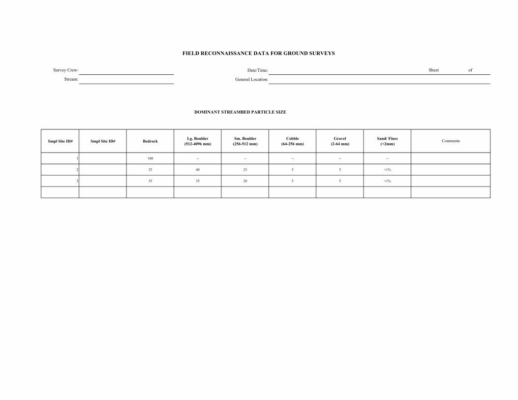
Date/Time:
General Location:
DOMINANT STREAMBED PARTICLE SIZE
Smpl Site ID# Smpl Site ID# Bedrock Lg. Boulder (512-4096 mm)
Sm. Boulder (256-512 mm)
Cobble (64-256 mm)
Gravel (2-64 mm)
Sand/ Fines (<2mm)
1 100 -- -- -- -- --
2 25 40 25 5 5 <1%
3 35 35 20 5 5 <1%
FIELD RECONNAISSANCE DATA FOR GROUND SURVEYS
Sheet of
Comments
Survey Crew:
Stream:

Survey Crew:Stream:
Smpl Site ID# Boulder
Shadow (none, few, many)
Bars (# in unit)
Pool Tail-Out/ Riffle
Associated with LWD
Scattered, Poorly Sorted
Boulder Shadow (none,
few, many)Bars (# in unit)
Associated with LWD
Interstitial spaces filled
Concentrated, Covering Bed
Pools (% on bed)
Comments
1 None -- -- -- -- None -- -- -- -- <5% No gravel, very little to no sand
2 Few -- -- -- x None -- -- -- -- 10-20
3 Few -- -- -- x Few -- -- -- -- 10-20
Lateral Mid-channel Point
1 A -- -- -- --
2 A -- -- -- --
3 A -- -- -- --
Comments
Sand Deposits
INSTREAM BARS
Presence/ Absence Count Active / Inactive Bar Particle Size Comp
Bar Type
FIELD RECONNAISSANCE DATA FOR GROUND SURVEYS
Date/Time:General Location:
Sheet of
GRAVEL and SAND DEPOSITIONAL FEATURESGravel Deposits
Smpl Site ID#
--
--
--
--
--
--
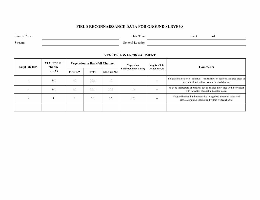
Survey Crew: Date/Time: Sheet of
Stream: General Location:
Vegetation in Bankfull Channel
POSTION TYPE SIZE CLASS
1 P(?) 1/2 2/3/5 1/2 1 --
2 P(?) 1/2 2/3/5 1/2/3 1/2 --
3 P 1 2/5 1/2 1/2 --
no good indincators of bankfull -->sheet flow on bedrock. Isolated areas of herb and alder/ willow with in wetted channel
no good indincators of bankfull due to briaded flow, area with herb./alder with in wetted channel in boulder matrix
No good bankfull indincators due to lage bed elements. Area with herb./alder along channel and within wetted channel
Comments
VEGETATION ENCROACHMENT
FIELD RECONNAISSANCE DATA FOR GROUND SURVEYS
Smpl Site ID# VEG w/in BF
channel (P/A)
Vegetation Encroachment Rating
Veg Sz. Cl. in Relict BF Ch.

Survey Crew: Date/Time: Sheet of
Stream: General Location:
Smpl Site ID# Erodibility (yes /no)
Bank Composition Instability Feature Causative Erosion Process SCI Stability Rating Comments
1 N 1 -- -- Stable Bedrock banks
2 N 1 -- -- Stable Large boulder/Bedrock
3 N 1 -- -- Stable Large boulder/Bedrock
FIELD RECONNAISSANCE DATA FOR GROUND SURVEYS
BANK STABILITY
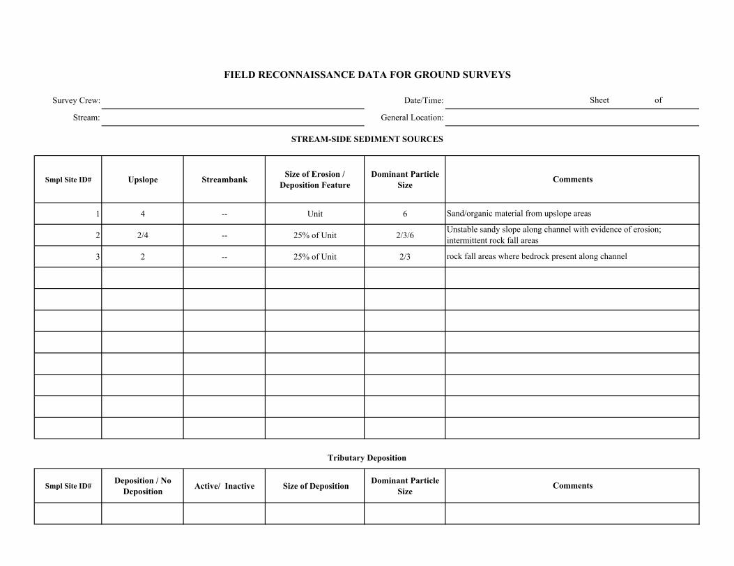
Survey Crew: Date/Time:
Stream: General Location:
Smpl Site ID# Upslope Streambank Size of Erosion / Deposition Feature
Dominant Particle Size
1 4 -- Unit 6
2 2/4 -- 25% of Unit 2/3/6
3 2 -- 25% of Unit 2/3
Smpl Site ID# Deposition / No
Deposition Active/ Inactive Size of Deposition Dominant Particle Size
Sheet of
FIELD RECONNAISSANCE DATA FOR GROUND SURVEYS
Comments
Tributary Deposition
STREAM-SIDE SEDIMENT SOURCES
Comments
Sand/organic material from upslope areas
Unstable sandy slope along channel with evidence of erosion; intermittent rock fall areas
rock fall areas where bedrock present along channel
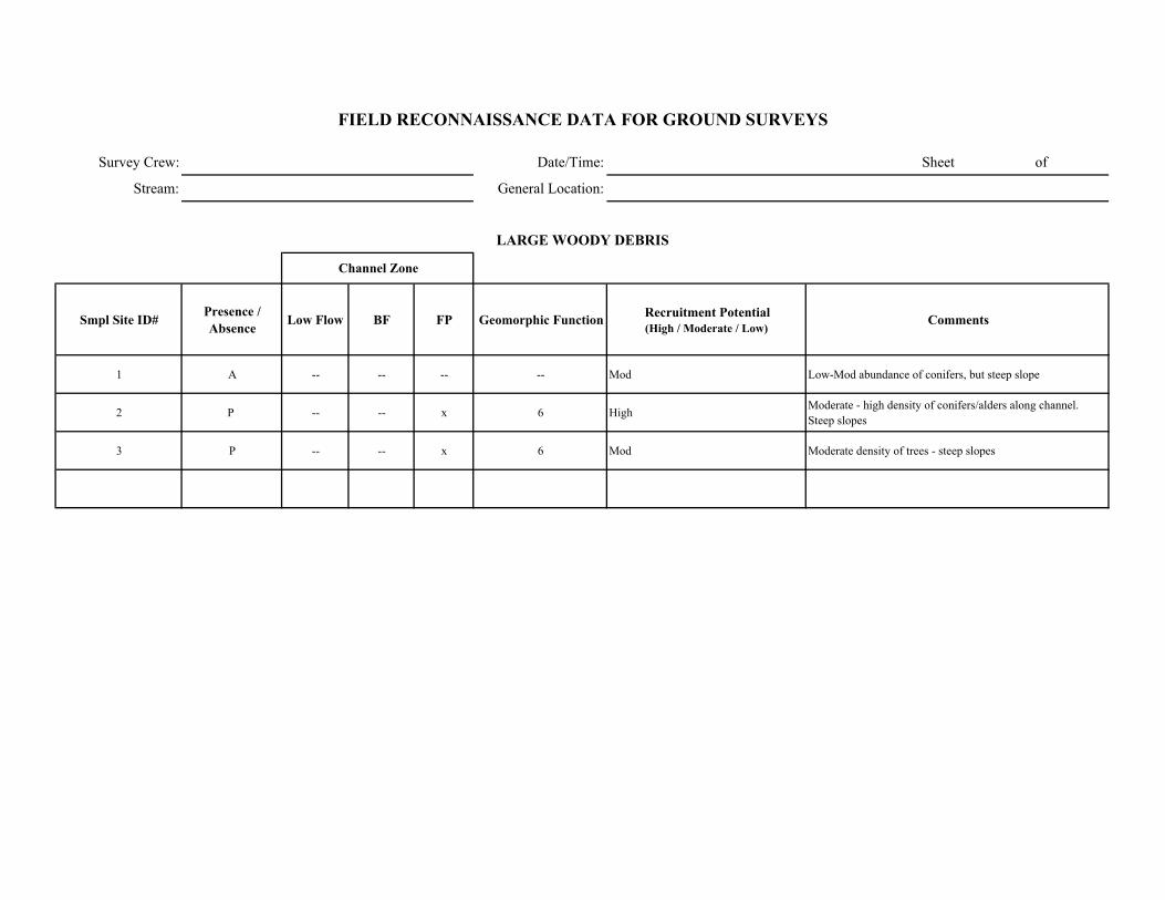
Survey Crew: Date/Time: Sheet of
Stream: General Location:
Smpl Site ID# Presence / Absence Low Flow BF FP Geomorphic Function Recruitment Potential
(High / Moderate / Low)Comments
1 A -- -- -- -- Mod Low-Mod abundance of conifers, but steep slope
2 P -- -- x 6 High Moderate - high density of conifers/alders along channel. Steep slopes
3 P -- -- x 6 Mod Moderate density of trees - steep slopes
FIELD RECONNAISSANCE DATA FOR GROUND SURVEYS
LARGE WOODY DEBRIS
Channel Zone
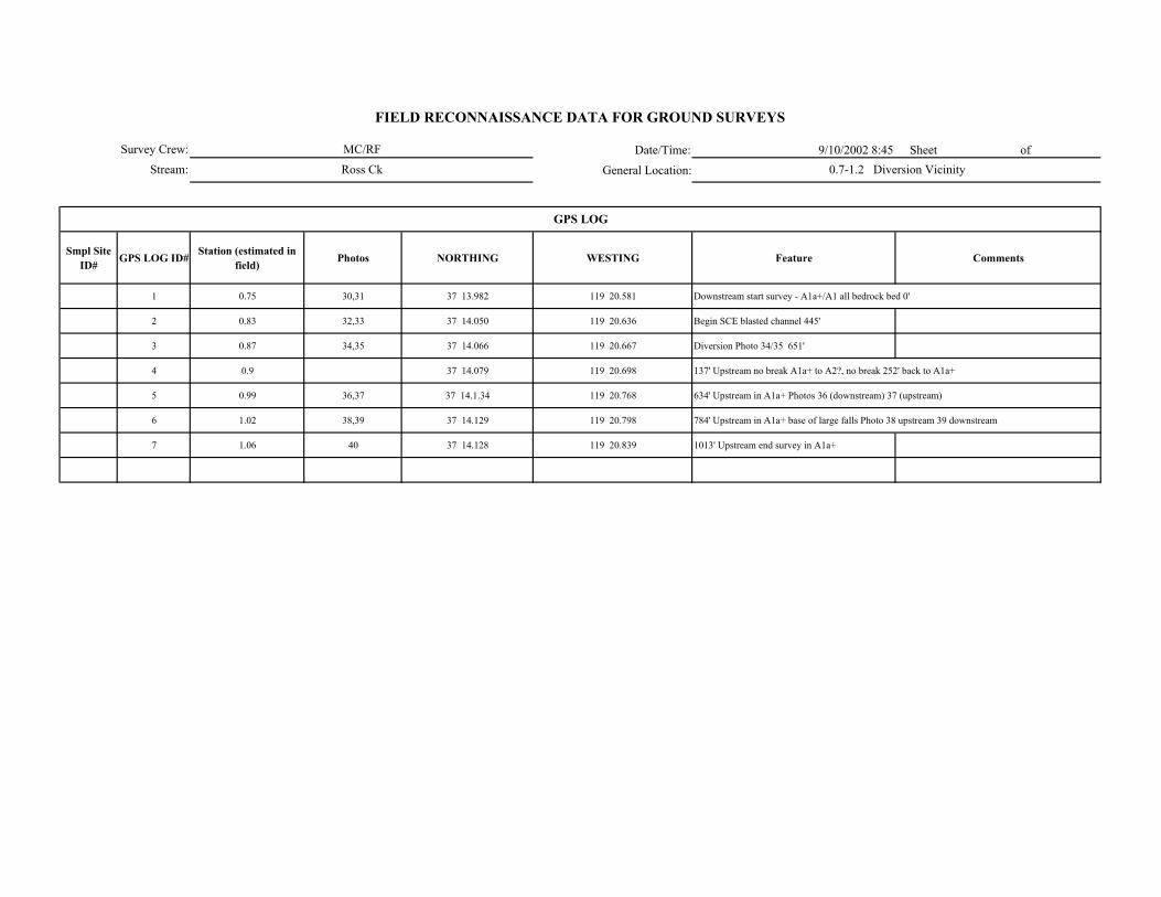
Date/Time: 9/10/2002 8:45 Sheet of
General Location:
Smpl Site ID# GPS LOG ID# Station (estimated in
field) Photos NORTHING WESTING Feature Comments
1 0.75 30,31 37 13.982 119 20.581 Downstream start survey - A1a+/A1 all bedrock bed 0'
2 0.83 32,33 37 14.050 119 20.636 Begin SCE blasted channel 445'
3 0.87 34,35 37 14.066 119 20.667 Diversion Photo 34/35 651'
4 0.9 37 14.079 119 20.698 137' Upstream no break A1a+ to A2?, no break 252' back to A1a+
5 0.99 36,37 37 14.1.34 119 20.768 634' Upstream in A1a+ Photos 36 (downstream) 37 (upstream)
6 1.02 38,39 37 14.129 119 20.798 784' Upstream in A1a+ base of large falls Photo 38 upstream 39 downstream
7 1.06 40 37 14.128 119 20.839 1013' Upstream end survey in A1a+
GPS LOG
Survey Crew:
Stream:
FIELD RECONNAISSANCE DATA FOR GROUND SURVEYS
MC/RF
Ross Ck 0.7-1.2 Diversion Vicinity
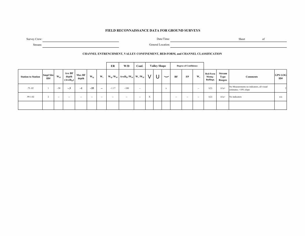
Survey Crew: Sheet of
Stream:
ER W/D Conf.
Station to Station Smpl Site ID#
Wbf
Ave BF depth
(AveDbf)
Max BF depth
Wfp Wv Wfp /Wbf AveDbf /Wbf Wv /Wbf V U ( BF FP Wv
Bed-Form Montg.-Buffingt.
Stream Type
RosgenComments GPS LOG
ID#
.75-.82 1 ~30 ~.3 ~1 ~35 -- ~1.17 ~100 -- x -- 1(2) A1a+ No Measurements no indicators, all visual estimates; >10% slope 2
.99-1.02 2 -- -- -- -- -- -- -- -- X -- -- -- 1(2) A1a+ No indicators n/a
FIELD RECONNAISSANCE DATA FOR GROUND SURVEYS
Degree of Confidence
CHANNEL ENTRENCHMENT, VALLEY CONFINEMENT, BED-FORM, and CHANNEL CLASSIFICATION
Valley Shape
Date/Time:
General Location:

Date/Time:
General Location:
DOMINANT STREAMBED PARTICLE SIZE
Smpl Site ID# Smpl Site ID# Bedrock Lg. Boulder (512-4096 mm)
Sm. Boulder (256-512 mm)
Cobble (64-256 mm)
Gravel (2-64 mm)
Sand/ Fines (<2mm)
2 1 100
-- 2 100
FIELD RECONNAISSANCE DATA FOR GROUND SURVEYS
Sheet of
Comments
few pool sand deposits
confined bedrock STP/CAS
Survey Crew:
Stream:

Survey Crew:Stream:
Smpl Site ID# Boulder
Shadow (none, few, many)
Bars (# in unit)
Pool Tail-Out/ Riffle
Associated with LWD
Scattered, Poorly Sorted
Boulder Shadow (none,
few, many)Bars (# in unit)
Associated with LWD
Interstitial spaces filled
Concentrated, Covering Bed
Pools (% on bed)
Comments
1 N 0 N N N N N N N N 5 Few pools
2 -- -- -- -- -- -- -- -- -- -- 10 when present
Lateral Mid-channel Point
1 A -- -- -- --
2 A -- -- -- --
Comments
Sand Deposits
INSTREAM BARS
Presence/ Absence Count Active / Inactive Bar Particle Size Comp
Bar Type
FIELD RECONNAISSANCE DATA FOR GROUND SURVEYS
Date/Time:General Location:
Sheet of
GRAVEL and SAND DEPOSITIONAL FEATURESGravel Deposits
Smpl Site ID#
--
--
--
--
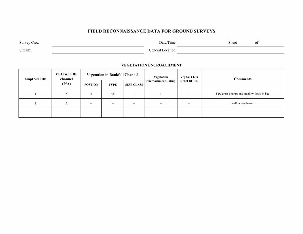
Survey Crew: Date/Time: Sheet of
Stream: General Location:
Vegetation in Bankfull Channel
POSTION TYPE SIZE CLASS
1 A 2 3/5 1 1 --
2 A -- -- -- -- --
Few grass clumps and small willows in bed
willows on banks
Comments
VEGETATION ENCROACHMENT
FIELD RECONNAISSANCE DATA FOR GROUND SURVEYS
Smpl Site ID# VEG w/in BF
channel (P/A)
Vegetation Encroachment Rating
Veg Sz. Cl. in Relict BF Ch.
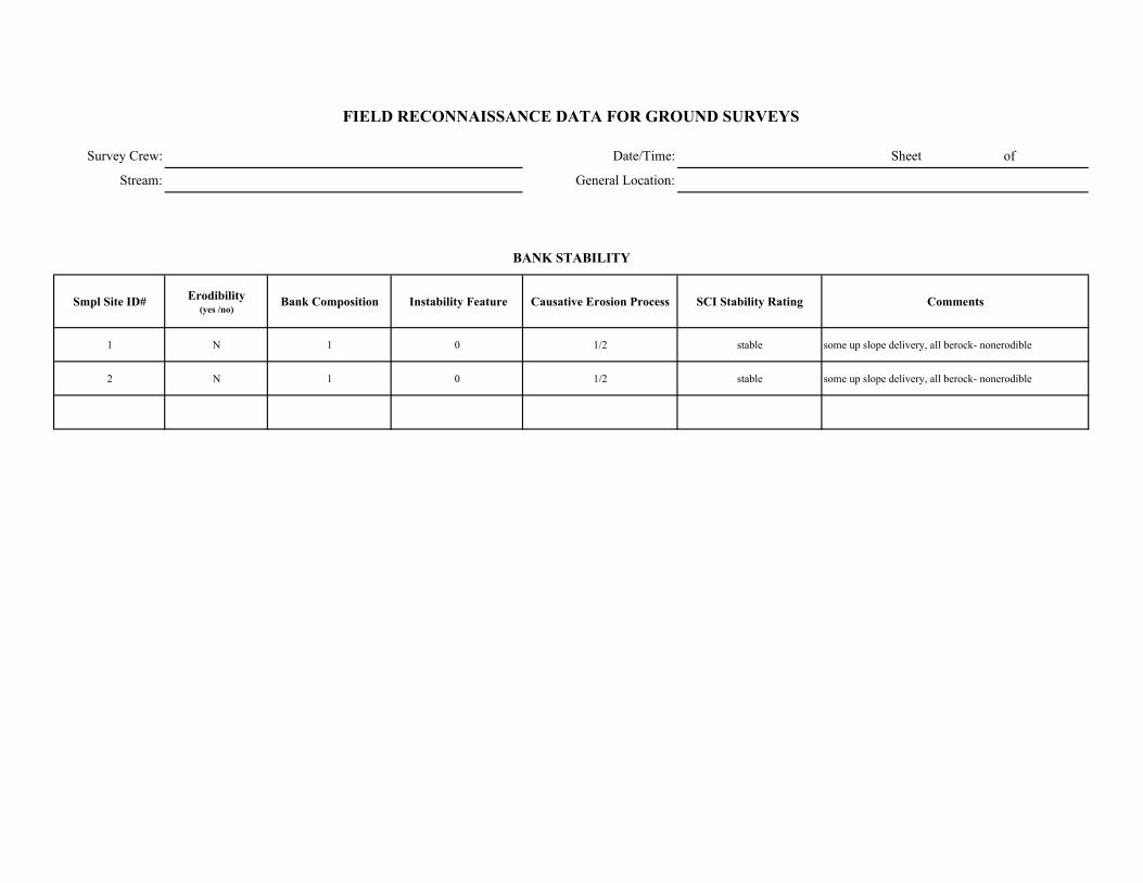
Survey Crew: Date/Time: Sheet of
Stream: General Location:
Smpl Site ID# Erodibility (yes /no)
Bank Composition Instability Feature Causative Erosion Process SCI Stability Rating Comments
1 N 1 0 1/2 stable some up slope delivery, all berock- nonerodible
2 N 1 0 1/2 stable some up slope delivery, all berock- nonerodible
FIELD RECONNAISSANCE DATA FOR GROUND SURVEYS
BANK STABILITY

Survey Crew: Date/Time:
Stream: General Location:
Smpl Site ID# Upslope Streambank Size of Erosion / Deposition Feature
Dominant Particle Size
1 4 if any -- <5% sand
2 5 if any -- <5% sand
Smpl Site ID# Deposition / No
Deposition Active/ Inactive Size of Deposition Dominant Particle Size
Sheet of
FIELD RECONNAISSANCE DATA FOR GROUND SURVEYS
Comments
Tributary Deposition
STREAM-SIDE SEDIMENT SOURCES
Comments
some upslope sand delivery
some upslope sand delivery
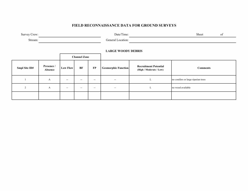
Survey Crew: Date/Time: Sheet of
Stream: General Location:
Smpl Site ID# Presence / Absence Low Flow BF FP Geomorphic Function Recruitment Potential
(High / Moderate / Low)Comments
1 A -- -- -- -- L no conifers or large riparian trees
2 A -- -- -- -- L no wood available
FIELD RECONNAISSANCE DATA FOR GROUND SURVEYS
LARGE WOODY DEBRIS
Channel Zone
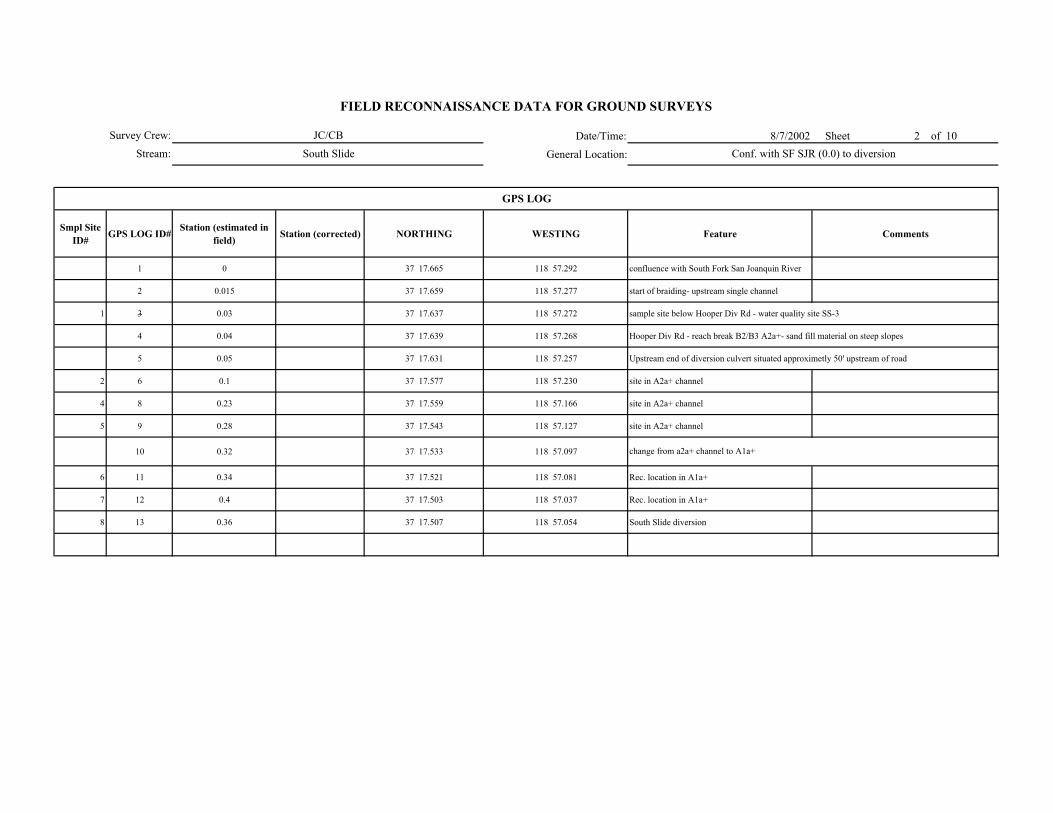
Date/Time: 8/7/2002 Sheet 2 of 10
General Location:
Smpl Site ID# GPS LOG ID# Station (estimated in
field) Station (corrected) NORTHING WESTING Feature Comments
1 0 37 17.665 118 57.292 confluence with South Fork San Joanquin River
2 0.015 37 17.659 118 57.277 start of braiding- upstream single channel
1 3 0.03 37 17.637 118 57.272 sample site below Hooper Div Rd - water quality site SS-3
4 0.04 37 17.639 118 57.268 Hooper Div Rd - reach break B2/B3 A2a+- sand fill material on steep slopes
5 0.05 37 17.631 118 57.257 Upstream end of diversion culvert situated approximetly 50' upstream of road
2 6 0.1 37 17.577 118 57.230 site in A2a+ channel
4 8 0.23 37 17.559 118 57.166 site in A2a+ channel
5 9 0.28 37 17.543 118 57.127 site in A2a+ channel
10 0.32 37 17.533 118 57.097
6 11 0.34 37 17.521 118 57.081 Rec. location in A1a+
7 12 0.4 37 17.503 118 57.037 Rec. location in A1a+
8 13 0.36 37 17.507 118 57.054 South Slide diversion
change from a2a+ channel to A1a+
GPS LOG
Survey Crew:
Stream:
FIELD RECONNAISSANCE DATA FOR GROUND SURVEYS
JC/CB
South Slide Conf. with SF SJR (0.0) to diversion
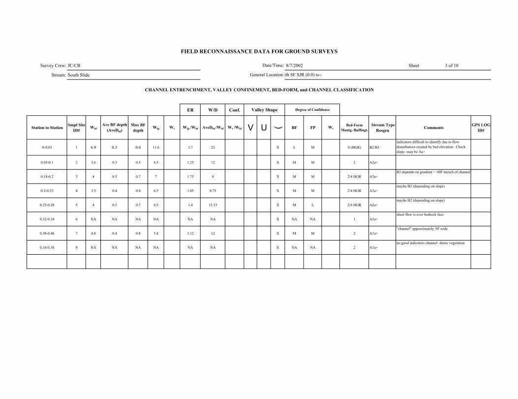
Survey Crew: JC/CB 8/7/2002 Sheet 3 of 10
Stream: South Slide
ER W/D Conf.
Station to Station Smpl Site ID#
WbfAve BF depth
(AveDbf)Max BF
depthWfp Wv Wfp /Wbf AveDbf /Wbf Wv /Wbf V U ( BF FP Wv
Bed-Form Montg.-Buffingt.
Stream Type Rosgen Comments GPS LOG
ID#
0-0.03 1 6.9 0.3 0.6 11.6 1.7 23 X L M 4 (HGR) B2/B3indicators difficult to identify due to flow disturbances created by bed elevation. Check slope- may be Aa+
0.05-0.1 2 3.6 0.3 0.5 4.5 1.25 12 X M M 3 A2a+
0.18-0.2 3 4 0.5 0.7 7 1.75 8 X M M 2/4 HGR A3a+B3 depends on gradient = 100' stretch of channel
0.2-0.23 4 3.5 0.4 0.8 6.5 1.85 8.75 X M M 2/4 HGR A2a+maybe B2 (depending on slope)
0.25-0.28 5 4 0.3 0.7 6.5 1.4 13.33 X M L 2/4 HGR A2a+maybe B2 (depending on slope)
0.32-0.34 6 NA NA NA NA NA NA X NA NA 1 A1a+sheet flow is over bedrock face
0.38-0.46 7 4.8 0.4 0.8 5.4 1.12 12 X M M 2 A1a+"channel" approximately 30' wide
0.34-0.36 8 NA NA NA NA NA NA X NA NA 2 A1a+no good indicators channel- dense vegetation
FIELD RECONNAISSANCE DATA FOR GROUND SURVEYS
Degree of Confidence
CHANNEL ENTRENCHMENT, VALLEY CONFINEMENT, BED-FORM, and CHANNEL CLASSIFICATION
Valley Shape
Date/Time:
General Location:ith SF SJR (0.0) to d
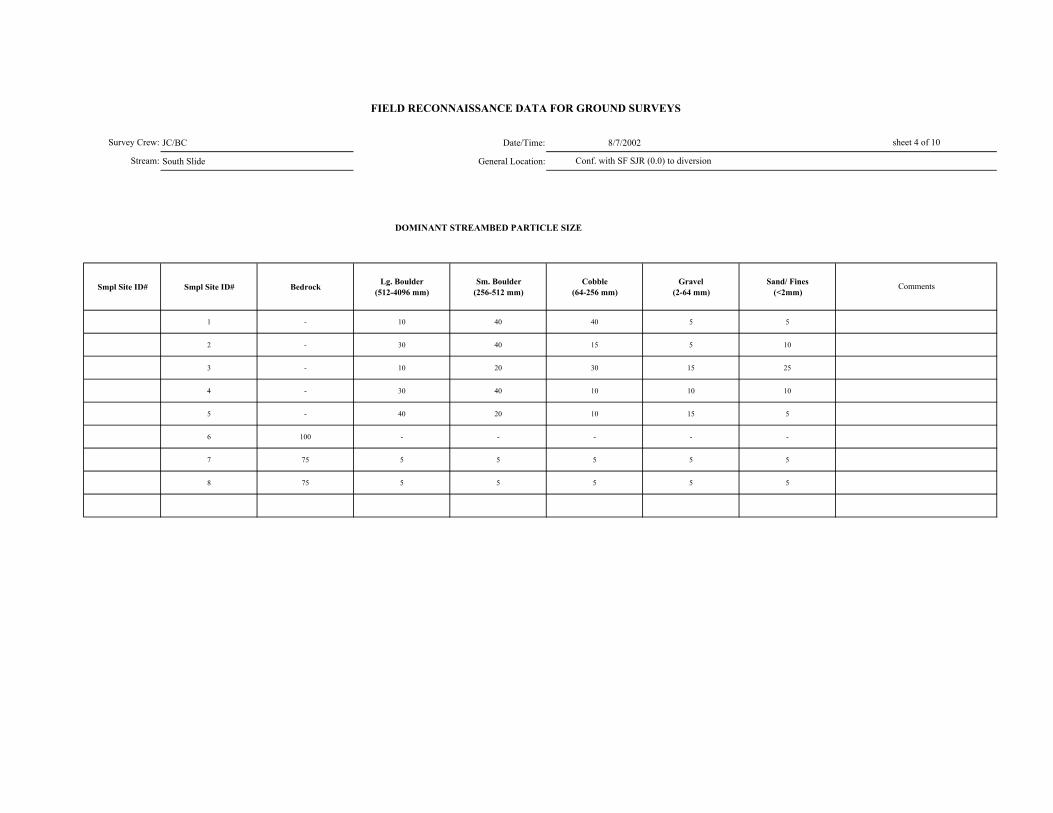
JC/BC Date/Time: 8/7/2002
South Slide General Location:
DOMINANT STREAMBED PARTICLE SIZE
Smpl Site ID# Smpl Site ID# Bedrock Lg. Boulder (512-4096 mm)
Sm. Boulder (256-512 mm)
Cobble (64-256 mm)
Gravel (2-64 mm)
Sand/ Fines (<2mm)
1 - 10 40 40 5 5
2 - 30 40 15 5 10
3 - 10 20 30 15 25
4 - 30 40 10 10 10
5 - 40 20 10 15 5
6 100 - - - - -
7 75 5 5 5 5 5
8 75 5 5 5 5 5
FIELD RECONNAISSANCE DATA FOR GROUND SURVEYS
sheet 4 of 10
Comments
Conf. with SF SJR (0.0) to diversion
Survey Crew:
Stream:
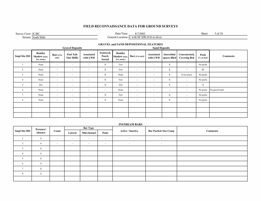
Survey Crew: JC/BC 8/7/2002Stream: South Slide
Smpl Site ID# Boulder
Shadow (none, few, many)
Bars (# in unit)
Pool Tail-Out/ Riffle
Associated with LWD
Scattered, Poorly Sorted
Boulder Shadow (none,
few, many)Bars (# in unit)
Associated with LWD
Interstitial spaces filled
Concentrated, Covering Bed
Pools (% on bed)
Comments
1 None - - - X Few - - X - No pools
2 None - - - X Few - - X - 80
3 None - - - X None - - X X (in areas) No pools
4 None - - - X Few - - X - No pools
5 few - - - X Few - - X - 15
6 None - - - - None - - - - No pools No gravel/sand
7 None - - - X Few - - X - No pools
8 None - - - X None - - X - No pools
Lateral Mid-channel Point
1 A - - - -
2 A - - - -
3 A
4 A
5 A
6 A
7 A
8 A
Comments
Sand Deposits
INSTREAM BARS
Presence/ Absence Count Active / Inactive Bar Particle Size Comp
Bar Type
FIELD RECONNAISSANCE DATA FOR GROUND SURVEYS
Date/Time:General Location:
Sheet 5 of 10
GRAVEL and SAND DEPOSITIONAL FEATURESGravel Deposits
Smpl Site ID#
nf. with SF SJR (0.0) to divers
-
-
-
-

Survey Crew: JC/CB Date/Time: 8/7/2002 sheet 6 of 10
Stream: South Slide General Location:
Vegetation in Bankfull Channel
POSTION TYPE SIZE CLASS
1 A - - - 1 -
2 A - - - 1 -
3 A - - - 1 -
4 A - - - 1 -
5 A - - - 1 -
6 A - - - 1 -
7 A - - - 1 -
8 A - - - 1 -
Immediately upstream of diversion P 2 2 2 Yes
Comments
VEGETATION ENCROACHMENT
FIELD RECONNAISSANCE DATA FOR GROUND SURVEYS
Smpl Site ID# VEG w/in BF
channel (P/A)
Vegetation Encroachment Rating
Veg Sz. Cl. in Relict BF Ch.
onf. with SF SJR (0.0) to diversio
Alder/ Willow/ perennial herb. in flood prone channel
Alder/ Willow/ perennial herb. in flood prone channel
Alder/ Willow/ perennial herb. in flood prone channel
alder/willow/aspen/ perennial herb. 1/2/3 within flood prone
alder/willow/aspen/ perennial herb. 1/2/3 within flood prone
vegetation along bedrock and in soil areas within bedrock face. vegetation- alder and perennial herb. along channel/bedrock
margin. Areas of soil which could be referred to as bars which are well vegetated with alder and perennial herb.
very thick dense vegetation along channel. inactive dense channel (1/2 age). Margin outside of flood plain area- alder dense
overhanging channel.
In general no, but very dense along margin and overhanging vegetation (dense)
1 large alder in middle of channel
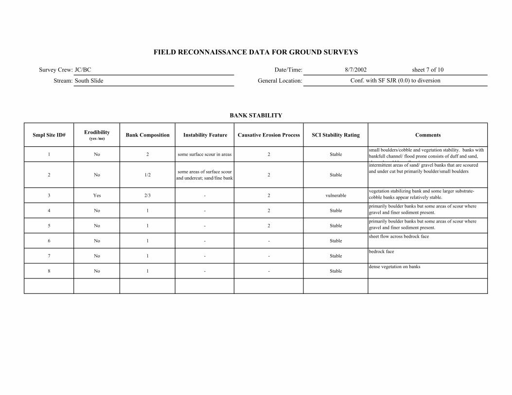
Survey Crew: JC/BC Date/Time: 8/7/2002 sheet 7 of 10
Stream: South Slide General Location:
Smpl Site ID# Erodibility (yes /no)
Bank Composition Instability Feature Causative Erosion Process SCI Stability Rating Comments
1 No 2 some surface scour in areas 2 Stablesmall boulders/cobble and vegetation stability. banks with bankfull channel/ flood prone consists of duff and sand, h l ld l t ll i t
2 No 1/2 some areas of surface scour and undercut; sand/fine bank 2 Stable
intermittent areas of sand/ gravel banks that are scoured and under cut but primarily boulder/small boulders
3 Yes 2/3 - 2 vulnerablevegetation stabilizing bank and some larger substrate- cobble banks appear relatively stable.
4 No 1 - 2 Stableprimarily boulder banks but some areas of scour where gravel and finer sediment present.
5 No 1 - 2 Stableprimarily boulder banks but some areas of scour where gravel and finer sediment present.
6 No 1 - - Stablesheet flow across bedrock face
7 No 1 - - Stablebedrock face
8 No 1 - - Stabledense vegetation on banks
FIELD RECONNAISSANCE DATA FOR GROUND SURVEYS
BANK STABILITY
Conf. with SF SJR (0.0) to diversion
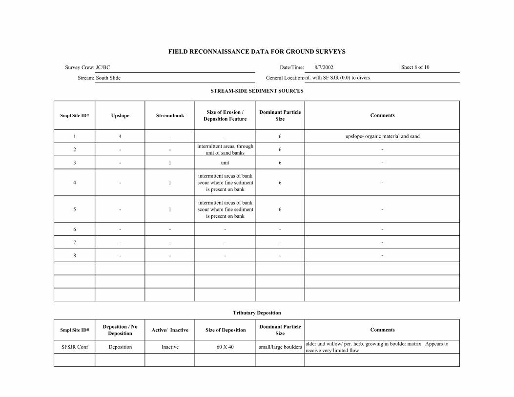
Survey Crew: JC/BC Date/Time: 8/7/2002
Stream: South Slide General Location:
Smpl Site ID# Upslope Streambank Size of Erosion / Deposition Feature
Dominant Particle Size
1 4 - - 6
2 - - intermittent areas, through unit of sand banks 6
3 - 1 unit 6
4 - 1intermittent areas of bank scour where fine sediment
is present on bank6
5 - 1intermittent areas of bank scour where fine sediment
is present on bank6
6 - - - -
7 - - - -
8 - - - -
Smpl Site ID# Deposition / No
Deposition Active/ Inactive Size of Deposition Dominant Particle Size
SFSJR Conf Deposition Inactive 60 X 40 small/large boulders
Sheet 8 of 10
FIELD RECONNAISSANCE DATA FOR GROUND SURVEYS
Comments
Tributary Deposition
STREAM-SIDE SEDIMENT SOURCES
Comments
upslope- organic material and sand
-
-
-
alder and willow/ per. herb. growing in boulder matrix. Appears to receive very limited flow.
onf. with SF SJR (0.0) to diversi
-
-
-
-
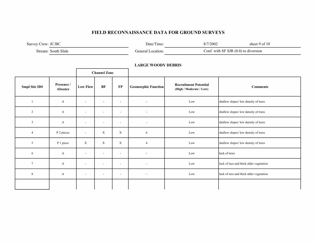
Survey Crew: JC/BC Date/Time: 8/7/2002 sheet 9 of 10
Stream: South Slide General Location:
Smpl Site ID# Presence / Absence Low Flow BF FP Geomorphic Function Recruitment Potential
(High / Moderate / Low)Comments
1 A - - - - Low shallow slopes/ low density of trees
2 A - - - - Low shallow slopes/ low density of trees
3 A - - - - Low shallow slopes/ low density of trees
4 P 2 pieces - X X 6 Low shallow slopes/ low density of trees
5 P 1 piece X X X 4 Low shallow slopes/ low density of trees
6 A - - - - Low lack of trees
7 A - - - - Low lack of tees and thick alder vegetation
8 A - - - - Low lack of tees and thick alder vegetation
FIELD RECONNAISSANCE DATA FOR GROUND SURVEYS
LARGE WOODY DEBRIS
Channel Zone
Conf. with SF SJR (0.0) to diversion
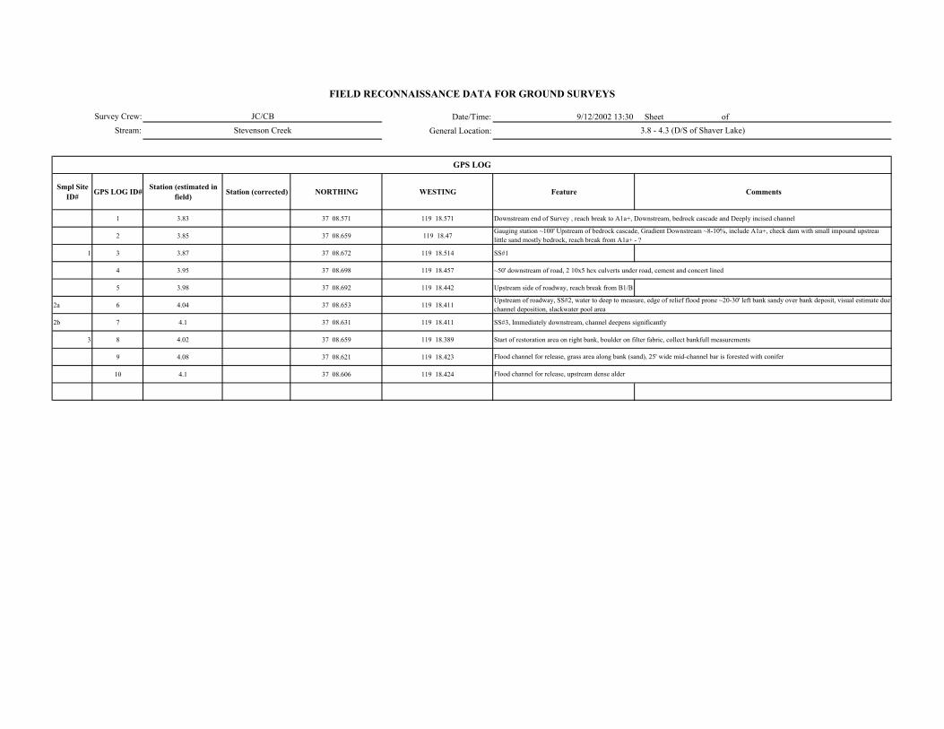
Date/Time: 9/12/2002 13:30 Sheet of General Location:
Smpl Site ID# GPS LOG ID# Station (estimated in
field) Station (corrected) NORTHING WESTING Feature Comments
1 3.83 37 08.571 119 18.571 Downstream end of Survey , reach break to A1a+, Downstream, bedrock cascade and Deeply incised channel
2 3.85 37 08.659 119 18.47
1 3 3.87 37 08.672 119 18.514 SS#1
4 3.95 37 08.698 119 18.457 ~50' downstream of road, 2 10x5 hex culverts under road, cement and concert lined
5 3.98 37 08.692 119 18.442 Upstream side of roadway, reach break from B1/B
2a 6 4.04 37 08.653 119 18.411
2b 7 4.1 37 08.631 119 18.411 SS#3, Immediately downstream, channel deepens significantly
3 8 4.02 37 08.659 119 18.389 Start of restoration area on right bank, boulder on filter fabric, collect bankfull measurements
9 4.08 37 08.621 119 18.423
10 4.1 37 08.606 119 18.424
Gauging station ~100' Upstream of bedrock cascade, Gradient Downstream ~8-10%, include A1a+, check dam with small impound upstreamlittle sand mostly bedrock, reach break from A1a+ - ?
Upstream of roadway, SS#2, water to deep to measure, edge of relief flood prone ~20-30' left bank sandy over bank deposit, visual estimate due channel deposition, slackwater pool area
Flood channel for release, grass area along bank (sand), 25' wide mid-channel bar is forested with conifer
Flood channel for release, upstream dense alder
GPS LOG
Survey Crew:Stream:
FIELD RECONNAISSANCE DATA FOR GROUND SURVEYS
JC/CBStevenson Creek 3.8 - 4.3 (D/S of Shaver Lake)

Survey Crew: Sheet of
Stream:
ER W/D Conf.
Station to Station Smpl Site ID#
Wbf
Ave BF depth
(AveDbf)
Max BF depth
Wfp Wv Wfp /Wbf AveDbf /Wbf Wv /Wbf V U ( BF FP Wv
Bed-Form Montg.-Buffingt.
Stream Type
RosgenComments GPS
LOG ID#
3.85 - 3.90 1 12.7 0.5 0.7 22 1.7 25.4 x H H 4 B1 Flow near bankfull, high width depth ratio due to bedrock
3.90-3.95 5.5 1 1.3 14.5 5.5 x H H 4 Rosgen type aftected by culvert
4.0-4.1 2a 20 3 4 30-50 1.5-1.8 6.7 x H H 4 B5(E5?) visual esimate due to deep channel, pool slackwater upstream of road, no riffle, channel has widened E-like look
4.1-? 2b 16 1.8 2.4 50 3.13 8.9 x H L 4 E5? Slackwater area
2b 30 1.8 2.4 2.5
4.08-GPS 3 21 2.5 3 34 1.6 8.4 x H L 4 B2/B5 Rip rap on right bank
FIELD RECONNAISSANCE DATA FOR GROUND SURVEYS
Degree of Confidence
CHANNEL ENTRENCHMENT, VALLEY CONFINEMENT, BED-FORM, and CHANNEL CLASSIFICATION
Valley Shape
Date/Time:
General Location:
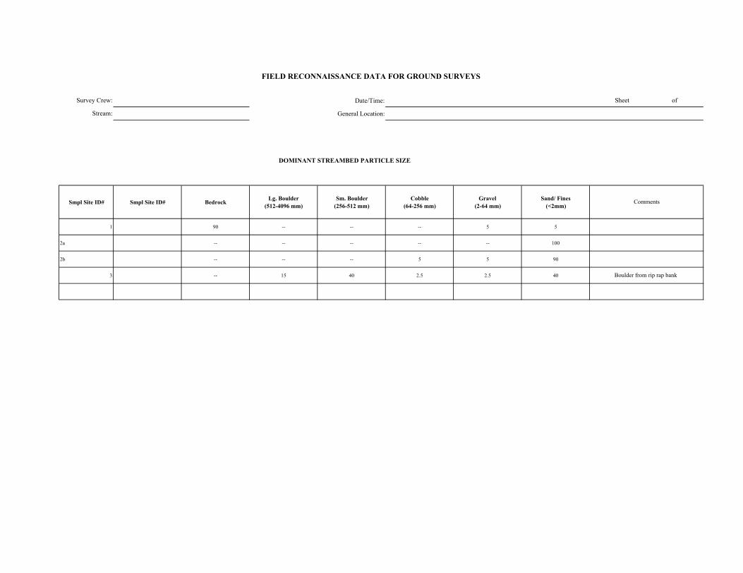
Date/Time:
General Location:
DOMINANT STREAMBED PARTICLE SIZE
Smpl Site ID# Smpl Site ID# Bedrock Lg. Boulder (512-4096 mm)
Sm. Boulder (256-512 mm)
Cobble (64-256 mm)
Gravel (2-64 mm)
Sand/ Fines (<2mm)
1 90 -- -- -- 5 5
2a -- -- -- -- -- 100
2b -- -- -- 5 5 90
3 -- 15 40 2.5 2.5 40
Survey Crew:
Stream:
Boulder from rip rap bank
FIELD RECONNAISSANCE DATA FOR GROUND SURVEYS
Sheet of
Comments
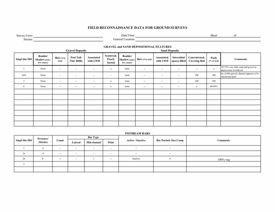
Survey Crew:Stream:
Smpl Site ID# Boulder
Shadow (none, few, many)
Bars (# in unit)
Pool Tail-Out/ Riffle
Associated with LWD
Scattered, Poorly Sorted
Boulder Shadow (none,
few, many)Bars (# in unit)
Associated with LWD
Interstitial spaces filled
Concentrated, Covering Bed
Pools (% on bed)
Comments
1 None -- -- -- x none -- -- -- -- x 10-15% very little sand and gravel in depressions in bedrock
2a/b None -- -- -- -- none -- -- -- 100 100 no visible gravel, channel appears to be slackwater/pool
3 None -- -- -- x none -- -- -- 100 100
6 None -- -- -- x none -- -- -- x 80-90%
Lateral Mid-channel Point
1 A -- -- -- --
2a A -- -- -- --
2b P 1 -- 1 --
3
--
--
Inactive
--
--
6 100% veg
FIELD RECONNAISSANCE DATA FOR GROUND SURVEYS
Date/Time:General Location:
Sheet of
GRAVEL and SAND DEPOSITIONAL FEATURESGravel Deposits
Smpl Site ID# Comments
Sand Deposits
INSTREAM BARS
Presence/ Absence Count Active / Inactive Bar Particle Size Comp
Bar Type
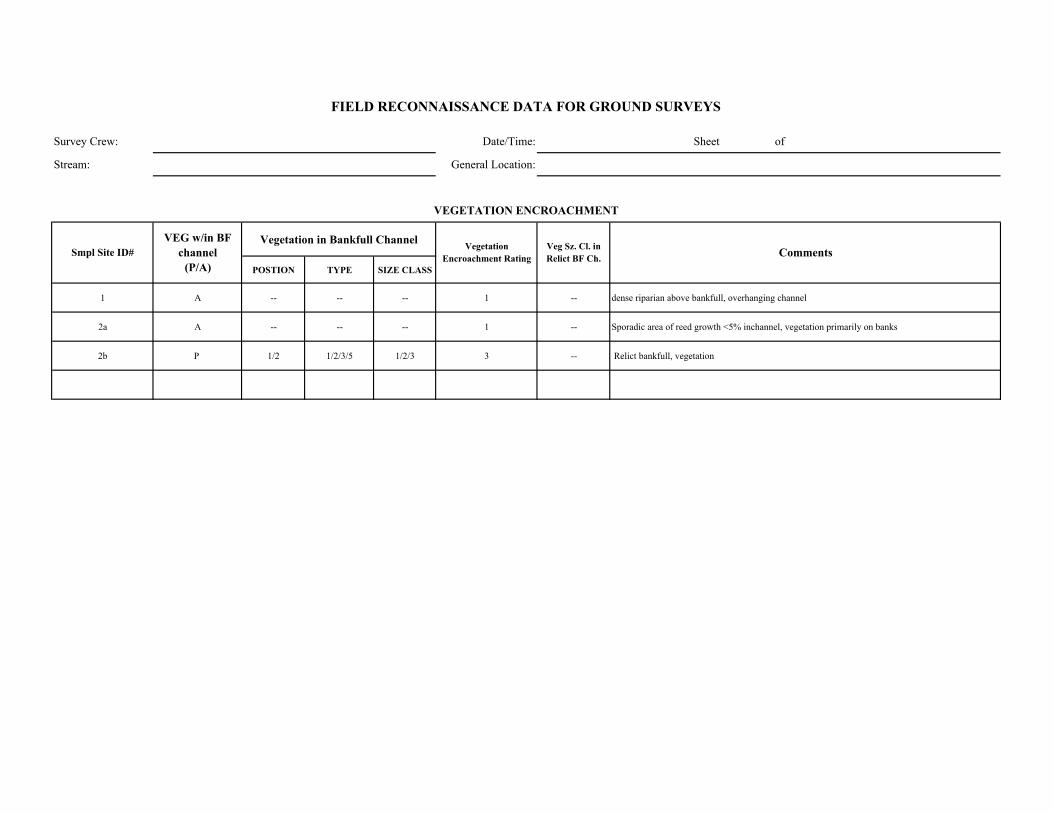
Survey Crew: Date/Time: Sheet of
Stream: General Location:
Vegetation in Bankfull Channel
POSTION TYPE SIZE CLASS
1 A -- -- -- 1 -- dense riparian above bankfull, overhanging channel
2a A -- -- -- 1 -- Sporadic area of reed growth <5% inchannel, vegetation primarily on banks
2b P 1/2 1/2/3/5 1/2/3 3 -- Relict bankfull, vegetation
Comments
VEGETATION ENCROACHMENT
FIELD RECONNAISSANCE DATA FOR GROUND SURVEYS
Smpl Site ID# VEG w/in BF
channel (P/A)
Vegetation Encroachment Rating
Veg Sz. Cl. in Relict BF Ch.
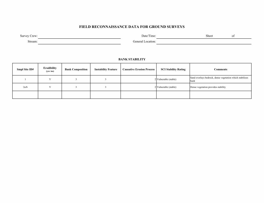
Survey Crew: Date/Time: Sheet of
Stream: General Location:
Smpl Site ID# Erodibility (yes /no)
Bank Composition Instability Feature Causative Erosion Process SCI Stability Rating Comments
1 Y 3 3 2 Vulnerable (stable) Sand overlays bedrock, dense vegetation which stabilizes bank
2a/b Y 3 3 2 Vulnerable (stable) Dense vegetation provides stability
FIELD RECONNAISSANCE DATA FOR GROUND SURVEYS
BANK STABILITY

Survey Crew: Date/Time:
Stream: General Location:
Smpl Site ID# Upslope Streambank Size of Erosion / Deposition Feature
Dominant Particle Size
1 4 -- unit 6
2a/b 100% upstream of road, road fill, sand 2 unit 6
Smpl Site ID# Deposition / No
Deposition Active/ Inactive Size of Deposition Dominant Particle Size
Sheet of
FIELD RECONNAISSANCE DATA FOR GROUND SURVEYS
Comments
Tributary Deposition
STREAM-SIDE SEDIMENT SOURCES
Comments
Small amounts of sand/organic material from upslope

Survey Crew: Date/Time: Sheet of
Stream: General Location:
Smpl Site ID# Presence / Absence Low Flow BF FP Geomorphic Function Recruitment Potential
(High / Moderate / Low)Comments
1 P x x x 1/6 low - mod Low - moderate density of conifers, moderate slopes RB/Low slope RB
2a/b P x x x 6 mod Moderate density of trees a long channel / low slopes
FIELD RECONNAISSANCE DATA FOR GROUND SURVEYS
LARGE WOODY DEBRIS
Channel Zone
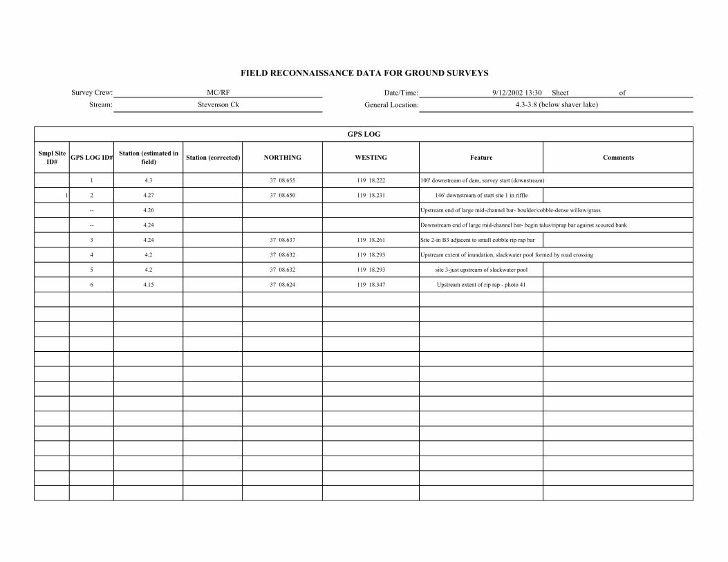
Date/Time: 9/12/2002 13:30 Sheet of General Location:
Smpl Site ID# GPS LOG ID# Station (estimated in
field) Station (corrected) NORTHING WESTING Feature Comments
1 4.3 37 08.655 119 18.222 100' downstream of dam, survey start (downstream)
1 2 4.27 37 08.650 119 18.231 146' downstream of start site 1 in riffle
-- 4.26 Upstream end of large mid-channel bar- boulder/cobble-dense willow/grass
-- 4.24 Downstream end of large mid-channel bar- begin talus/riprap bar against scoured bank
3 4.24 37 08.637 119 18.261 Site 2-in B3 adjacent to small cobble rip rap bar
4 4.2 37 08.632 119 18.293 Upstream extent of inundation, slackwater pool formed by road crossing
5 4.2 37 08.632 119 18.293 site 3-just upstream of slackwater pool
6 4.15 37 08.624 119 18.347 Upstream extent of rip rap - photo 41
GPS LOG
Survey Crew:Stream:
FIELD RECONNAISSANCE DATA FOR GROUND SURVEYS
MC/RFStevenson Ck 4.3-3.8 (below shaver lake)
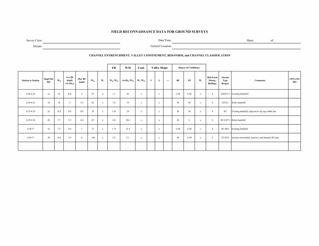
Survey Crew: Sheet of
Stream:
ER W/D Conf.
Station to Station Smpl Site ID#
Wbf
Ave BF depth
(AveDbf)
Max BF depth
Wfp Wv Wfp /Wbf AveDbf /Wbf Wv /Wbf V U ( BF FP Wv
Bed-Form Montg.-Buffingt.
Stream Type
RosgenComments GPS LOG
ID#
4.30-4.25 1a 25 0.6 1 27 x 1.1 42 x x L/M L/M x 4 G/B/F2/3 Existing bankfull?
4.30-4.25 1b 30 3 3.5 42 x 1.4 10 x x M M x 4 G3/G2 Relict bankfull
4.25-4.24 2a 14.5 0.6 0.8 24 x 1.65 24 x x M M x 4 B3 Existing bankfull, adjacent to rip rap cobble bar
4.25-4.24 2b 37 3.5 4.4 67 x 1.81 10.6 x x M L x 4 B3 (G3?) Relict bankfull
4.20-?? 3a 7.5 0.6 1 13 x 1.73 12.5 x x L/M L/M x 4 B3 (B5) Existing bankfull
4.20-?? 3b 18.5 3.6 4 ~60 x 3.2 5.1 x x M L/M x 4 E3 (E5) incision entrenched, narrows, and deepens B3 type
FIELD RECONNAISSANCE DATA FOR GROUND SURVEYS
Degree of Confidence
CHANNEL ENTRENCHMENT, VALLEY CONFINEMENT, BED-FORM, and CHANNEL CLASSIFICATION
Valley Shape
Date/Time:
General Location:
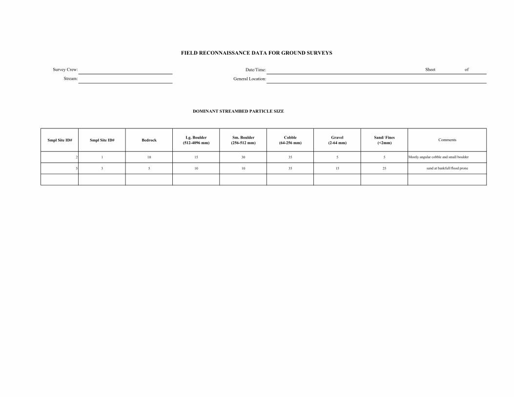
Date/Time:
General Location:
DOMINANT STREAMBED PARTICLE SIZE
Smpl Site ID# Smpl Site ID# Bedrock Lg. Boulder (512-4096 mm)
Sm. Boulder (256-512 mm)
Cobble (64-256 mm)
Gravel (2-64 mm)
Sand/ Fines (<2mm)
2 1 10 15 30 35 5 5
5 3 5 10 10 35 15 25
FIELD RECONNAISSANCE DATA FOR GROUND SURVEYS
Sheet of
Comments
Mostly angular cobble and small boulder
sand at bankfull/flood prone
Survey Crew:
Stream:
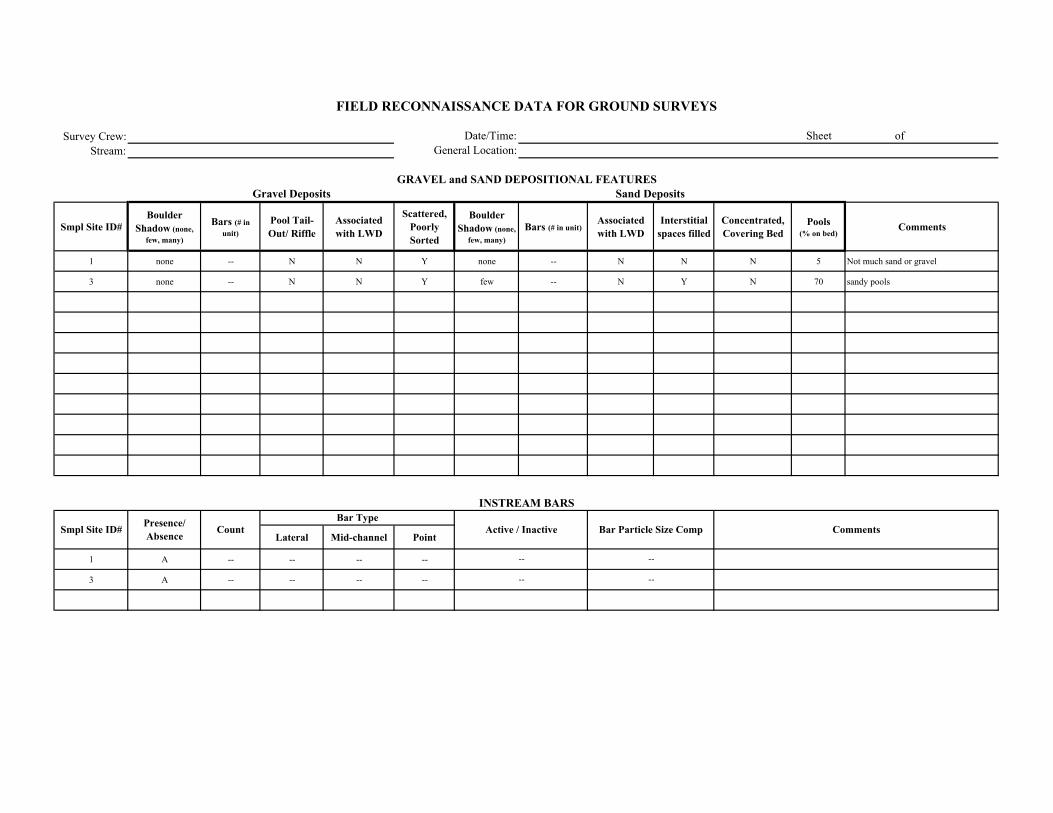
Survey Crew:Stream:
Smpl Site ID# Boulder
Shadow (none, few, many)
Bars (# in unit)
Pool Tail-Out/ Riffle
Associated with LWD
Scattered, Poorly Sorted
Boulder Shadow (none,
few, many)Bars (# in unit)
Associated with LWD
Interstitial spaces filled
Concentrated, Covering Bed
Pools (% on bed)
Comments
1 none -- N N Y none -- N N N 5 Not much sand or gravel
3 none -- N N Y few -- N Y N 70 sandy pools
Lateral Mid-channel Point
1 A -- -- -- --
3 A -- -- -- --
Comments
Sand Deposits
INSTREAM BARS
Presence/ Absence Count Active / Inactive Bar Particle Size Comp
Bar Type
FIELD RECONNAISSANCE DATA FOR GROUND SURVEYS
Date/Time:General Location:
Sheet of
GRAVEL and SAND DEPOSITIONAL FEATURESGravel Deposits
Smpl Site ID#
--
--
--
--
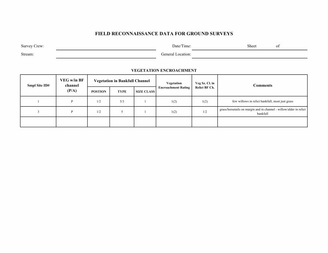
Survey Crew: Date/Time: Sheet of
Stream: General Location:
Vegetation in Bankfull Channel
POSTION TYPE SIZE CLASS
1 P 1/2 5/3 1 1(2) 1(2)
3 P 1/2 5 1 1(2) 1/2
few willows in relict bankfull, most just grass
grass/horsetails on margin and in channel - willow/alder in relict bankfull
Comments
VEGETATION ENCROACHMENT
FIELD RECONNAISSANCE DATA FOR GROUND SURVEYS
Smpl Site ID# VEG w/in BF
channel (P/A)
Vegetation Encroachment Rating
Veg Sz. Cl. in Relict BF Ch.
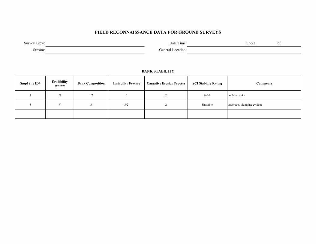
Survey Crew: Date/Time: Sheet of
Stream: General Location:
Smpl Site ID# Erodibility (yes /no)
Bank Composition Instability Feature Causative Erosion Process SCI Stability Rating Comments
1 N 1/2 0 2 Stable boulder banks
3 Y 3 3/2 2 Unstable undercuts, slumping evident
FIELD RECONNAISSANCE DATA FOR GROUND SURVEYS
BANK STABILITY

Survey Crew: Date/Time:
Stream: General Location:
Smpl Site ID# Upslope Streambank Size of Erosion / Deposition Feature
Dominant Particle Size
1 N/A (4 if any) 1 if any 5% unit sand
3 N/A (4 if any) 1/2/3 70% unit sand
Smpl Site ID# Deposition / No
Deposition Active/ Inactive Size of Deposition Dominant Particle Size
Sheet of
FIELD RECONNAISSANCE DATA FOR GROUND SURVEYS
Comments
Tributary Deposition
STREAM-SIDE SEDIMENT SOURCES
Comments
Bedrock/ Boulder bank cover, No sand in channel
almost all sandy banks
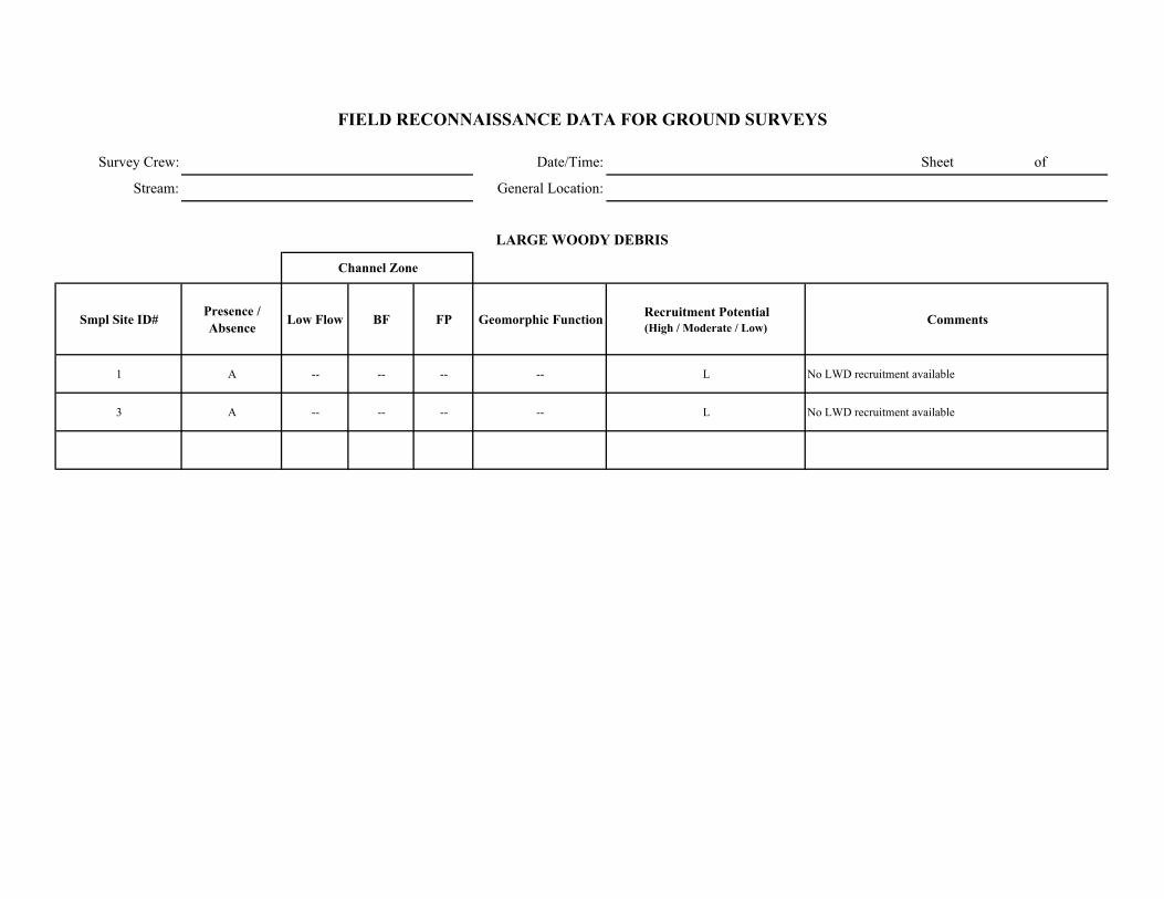
Survey Crew: Date/Time: Sheet of
Stream: General Location:
Smpl Site ID# Presence / Absence Low Flow BF FP Geomorphic Function Recruitment Potential
(High / Moderate / Low)Comments
1 A -- -- -- -- L No LWD recruitment available
3 A -- -- -- -- L No LWD recruitment available
FIELD RECONNAISSANCE DATA FOR GROUND SURVEYS
LARGE WOODY DEBRIS
Channel Zone
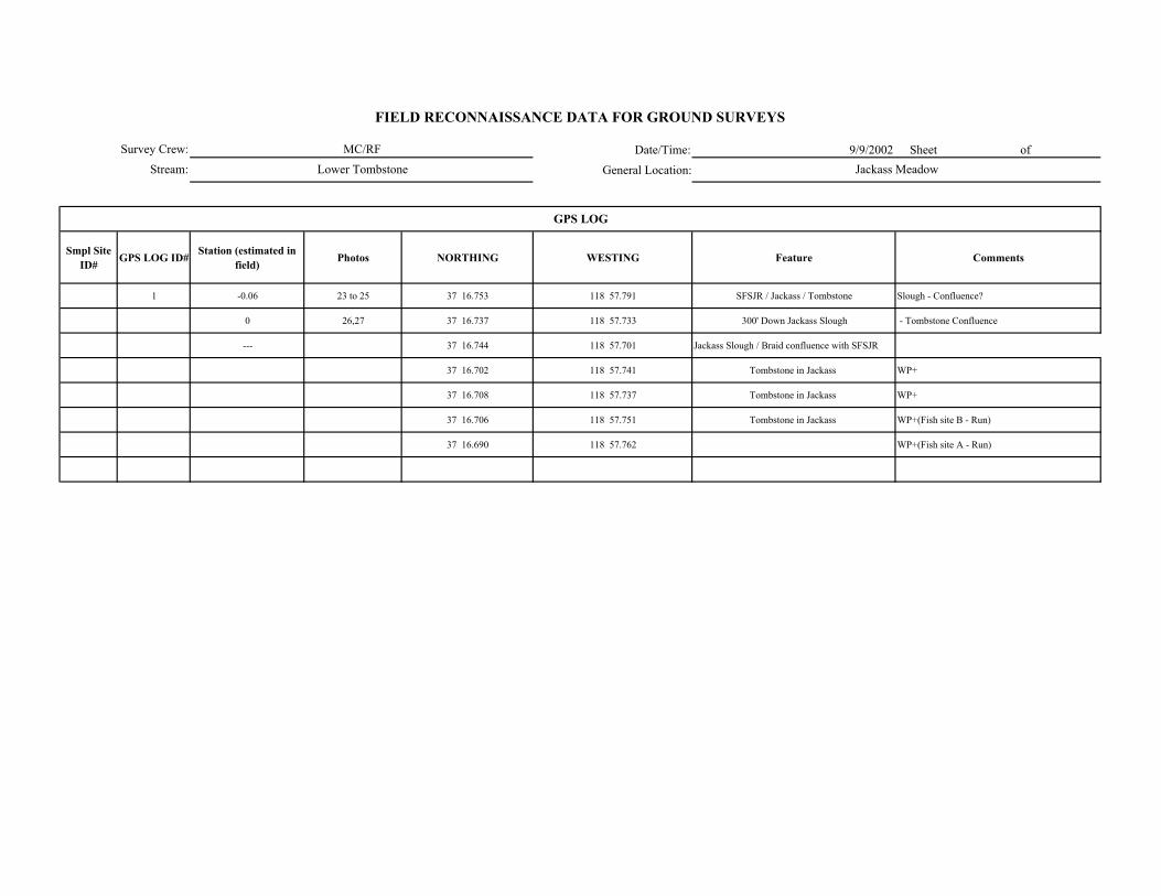
Date/Time: 9/9/2002 Sheet of
General Location:
Smpl Site ID# GPS LOG ID# Station (estimated in
field) Photos NORTHING WESTING Feature Comments
1 -0.06 23 to 25 37 16.753 118 57.791 SFSJR / Jackass / Tombstone Slough - Confluence?
0 26,27 37 16.737 118 57.733 300' Down Jackass Slough - Tombstone Confluence
--- 37 16.744 118 57.701 Jackass Slough / Braid confluence with SFSJR
37 16.702 118 57.741 Tombstone in Jackass WP+
37 16.708 118 57.737 Tombstone in Jackass WP+
37 16.706 118 57.751 Tombstone in Jackass WP+(Fish site B - Run)
37 16.690 118 57.762 WP+(Fish site A - Run)
GPS LOG
Survey Crew:
Stream:
FIELD RECONNAISSANCE DATA FOR GROUND SURVEYS
MC/RF
Lower Tombstone Jackass Meadow

Date/Time: 9/9/2002 Sheet of
General Location:
Smpl Site ID# GPS LOG ID# Station (estimated in
field) Station (corrected) NORTHING WESTING Feature Comments
1 0.6 37 16.560 118 57.567 Start Survey
1 2 0.53 37 16.559 118 57.592 SS#1 in E5
3 0.51 37 16.552 118 57.607 LWD jam fills channel - between 0.50-50.51-> reach break from E5 -> G5?
2 4 0.47 37 16.540 118 57.647 SS#2 ( = 20' downstream of footbridge)
5 0.43 37 16.536 118 57.646 Reach break from G5 -> E5
3 6 0.38 37 16.529 118 57.684 SS#3 in E5
7 0.31 37 16.503 118 57.735 Barbed wire fence crossing
4 8 0.29 37 16.502 118 57.754 SS#4 in E5
5 9 0.2 No GPS Coverage SS#5
10 0.13 37 16.627 118 57.759 Channel filled with sand - no defined bed/bank
> Channel widens, no bankfull indicators
6 11 0.09 37 16.667 118 57.752 SS#6
7 12 0.04 37 16.707 118 57.707 SS#7
GPS LOG
Survey Crew:
Stream:
FIELD RECONNAISSANCE DATA FOR GROUND SURVEYS
JC/CB
Tombstone Creek Station 0.0 - 0.6 D/S of Diversion
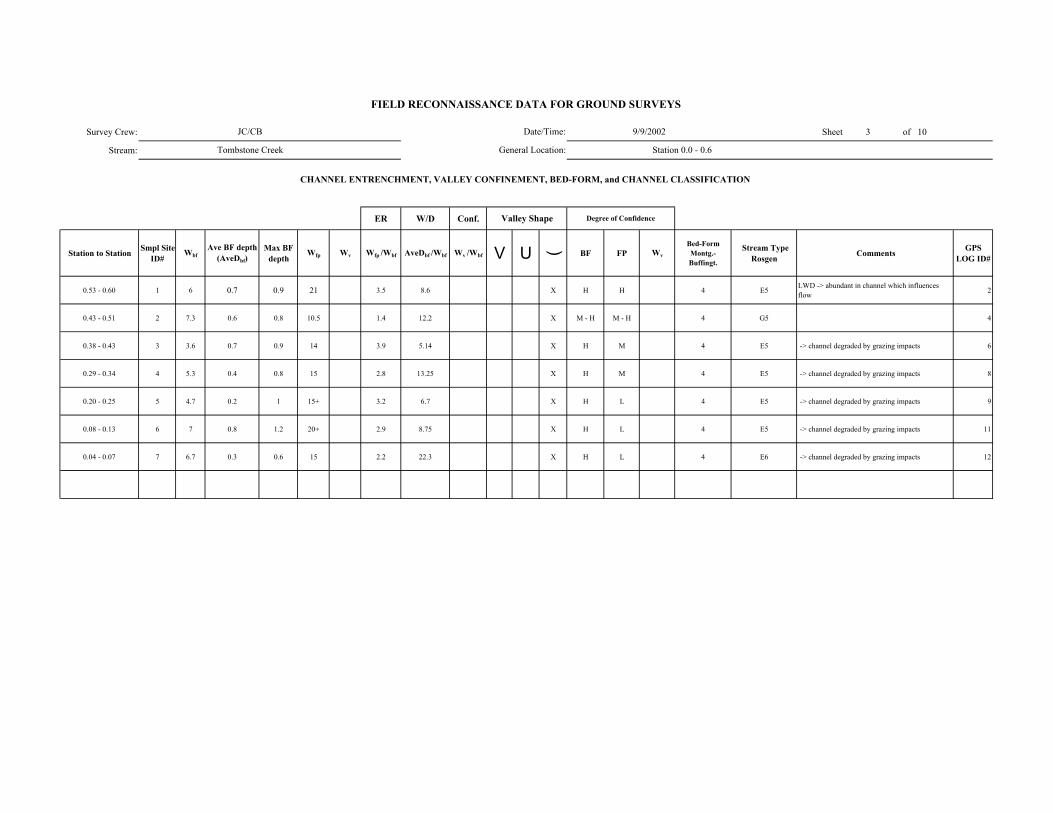
Survey Crew: Sheet 3 of 10
Stream:
ER W/D Conf.
Station to Station Smpl Site ID#
WbfAve BF depth
(AveDbf)Max BF
depthWfp Wv Wfp /Wbf AveDbf /Wbf Wv /Wbf V U ( BF FP Wv
Bed-Form Montg.-Buffingt.
Stream Type Rosgen Comments GPS
LOG ID#
0.53 - 0.60 1 6 0.7 0.9 21 3.5 8.6 X H H 4 E5 LWD -> abundant in channel which influences flow 2
0.43 - 0.51 2 7.3 0.6 0.8 10.5 1.4 12.2 X M - H M - H 4 G5 4
0.38 - 0.43 3 3.6 0.7 0.9 14 3.9 5.14 X H M 4 E5 -> channel degraded by grazing impacts 6
0.29 - 0.34 4 5.3 0.4 0.8 15 2.8 13.25 X H M 4 E5 -> channel degraded by grazing impacts 8
0.20 - 0.25 5 4.7 0.2 1 15+ 3.2 6.7 X H L 4 E5 -> channel degraded by grazing impacts 9
0.08 - 0.13 6 7 0.8 1.2 20+ 2.9 8.75 X H L 4 E5 -> channel degraded by grazing impacts 11
0.04 - 0.07 7 6.7 0.3 0.6 15 2.2 22.3 X H L 4 E6 -> channel degraded by grazing impacts 12
FIELD RECONNAISSANCE DATA FOR GROUND SURVEYS
Degree of Confidence
CHANNEL ENTRENCHMENT, VALLEY CONFINEMENT, BED-FORM, and CHANNEL CLASSIFICATION
Valley Shape
Date/Time:
General Location:
JC/CB
Tombstone Creek
9/9/2002
Station 0.0 - 0.6
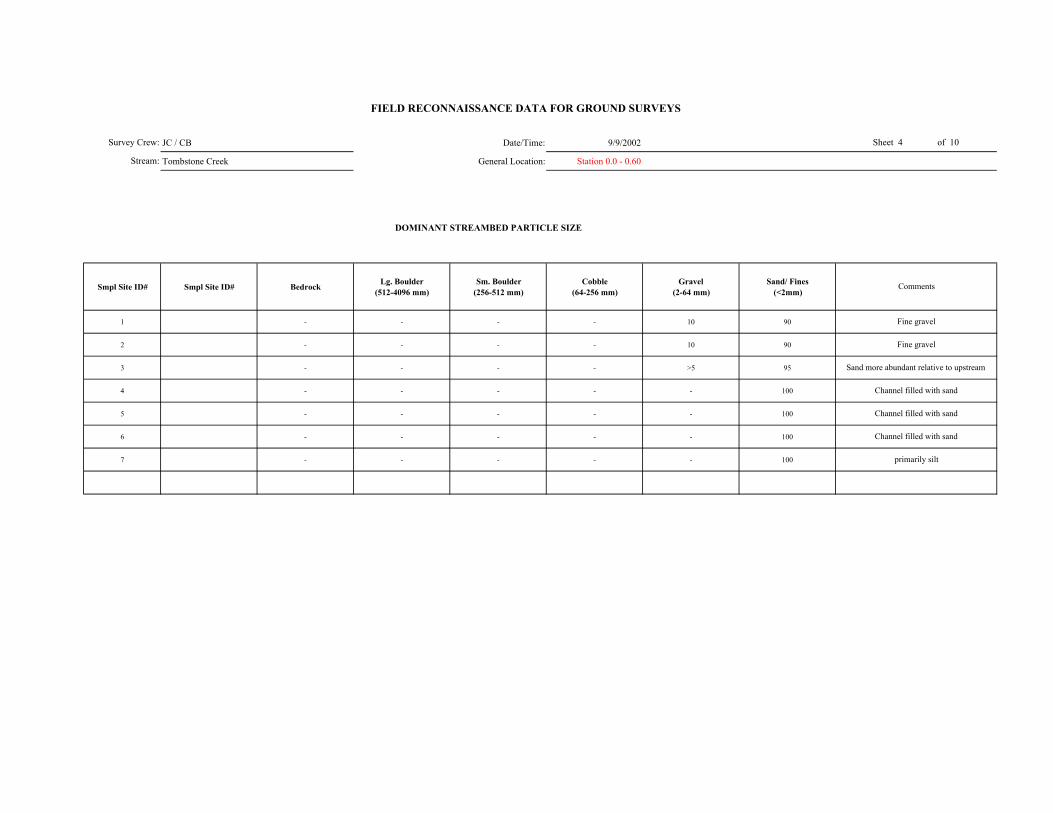
JC / CB Date/Time: 9/9/2002
Tombstone Creek General Location: Station 0.0 - 0.60
DOMINANT STREAMBED PARTICLE SIZE
Smpl Site ID# Smpl Site ID# Bedrock Lg. Boulder (512-4096 mm)
Sm. Boulder (256-512 mm)
Cobble (64-256 mm)
Gravel (2-64 mm)
Sand/ Fines (<2mm)
1 - - - - 10 90
2 - - - - 10 90
3 - - - - >5 95
4 - - - - - 100
5 - - - - - 100
6 - - - - - 100
7 - - - - - 100
Survey Crew:
Stream:
Channel filled with sand
primarily silt
Fine gravel
Sand more abundant relative to upstream
Channel filled with sand
Channel filled with sand
FIELD RECONNAISSANCE DATA FOR GROUND SURVEYS
Sheet 4 of 10
Comments
Fine gravel
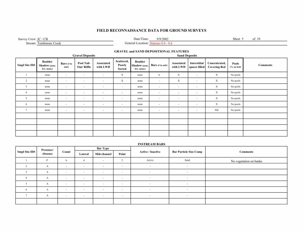
Survey Crew: JC / CB 9/9/2002Stream: Tombstone Creek Stations 0.0 - 0.6
Smpl Site ID# Boulder
Shadow (none, few, many)
Bars (# in unit)
Pool Tail-Out/ Riffle
Associated with LWD
Scattered, Poorly Sorted
Boulder Shadow (none,
few, many)Bars (# in unit)
Associated with LWD
Interstitial spaces filled
Concentrated, Covering Bed
Pools (% on bed)
Comments
1 none - - - X none 6 X - X No pools
2 none - - - X none - X - X No pools
3 none - - - - none - - - X No pools
4 none - - - - none - - - X No pools
5 none - - - - none - - - X No pools
6 none - - - - none - - - X No pools
7 none - - - - none - - - Silt No pools
Lateral Mid-channel Point
1 P 6 4 - 2
2 A - - - -
3 A - - - -
4 A - - - -
5 A - - - -
6 A - - - -
7 A - - - -
Active
-
-
-
-
-
-
Sand
-
-
-
-
-
-
No vegetation on banks
FIELD RECONNAISSANCE DATA FOR GROUND SURVEYS
Date/Time:General Location:
Sheet 5 of 10
GRAVEL and SAND DEPOSITIONAL FEATURESGravel Deposits
Smpl Site ID# Comments
Sand Deposits
INSTREAM BARS
Presence/ Absence Count Active / Inactive Bar Particle Size Comp
Bar Type
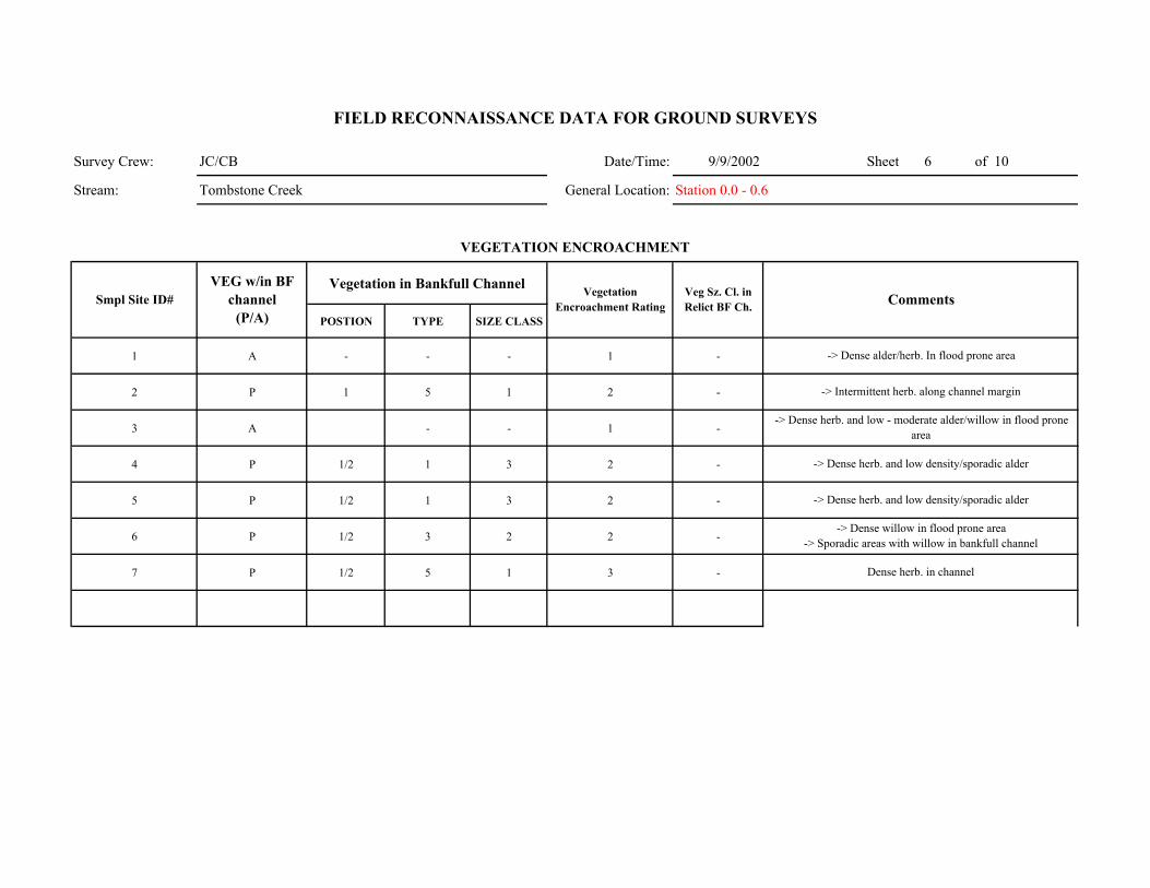
Survey Crew: JC/CB Date/Time: 9/9/2002 Sheet 6 of 10
Stream: Tombstone Creek General Location: Station 0.0 - 0.6
Vegetation in Bankfull Channel
POSTION TYPE SIZE CLASS
1 A - - - 1 -
2 P 1 5 1 2 -
3 A - - 1 -
4 P 1/2 1 3 2 -
5 P 1/2 1 3 2 -
6 P 1/2 3 2 2 -
7 P 1/2 5 1 3 -
FIELD RECONNAISSANCE DATA FOR GROUND SURVEYS
Smpl Site ID# VEG w/in BF
channel (P/A)
Vegetation Encroachment Rating
Veg Sz. Cl. in Relict BF Ch.
-> Dense alder/herb. In flood prone area
-> Intermittent herb. along channel margin
Comments
VEGETATION ENCROACHMENT
-> Dense herb. and low density/sporadic alder
-> Dense willow in flood prone area -> Sporadic areas with willow in bankfull channel
Dense herb. in channel
-> Dense herb. and low - moderate alder/willow in flood prone area
-> Dense herb. and low density/sporadic alder
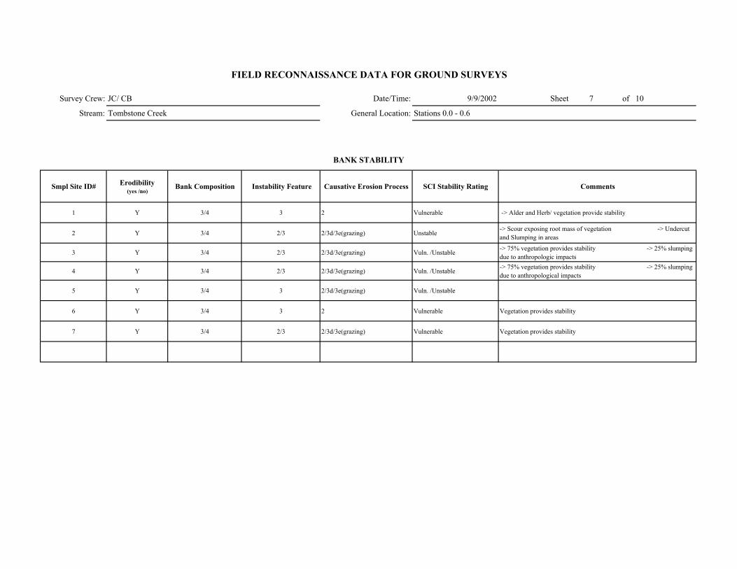
Survey Crew: JC/ CB Date/Time: 9/9/2002 Sheet 7 of 10
Stream: Tombstone Creek General Location: Stations 0.0 - 0.6
Smpl Site ID# Erodibility (yes /no)
Bank Composition Instability Feature Causative Erosion Process SCI Stability Rating Comments
1 Y 3/4 3 2 Vulnerable -> Alder and Herb/ vegetation provide stability
2 Y 3/4 2/3 2/3d/3e(grazing) Unstable-> Scour exposing root mass of vegetation -> Undercut and Slumping in areas
3 Y 3/4 2/3 2/3d/3e(grazing) Vuln. /Unstable -> 75% vegetation provides stability -> 25% slumping due to anthropologic impacts
4 Y 3/4 2/3 2/3d/3e(grazing) Vuln. /Unstable -> 75% vegetation provides stability -> 25% slumping due to anthropological impacts
5 Y 3/4 3 2/3d/3e(grazing) Vuln. /Unstable
6 Y 3/4 3 2 Vulnerable Vegetation provides stability
7 Y 3/4 2/3 2/3d/3e(grazing) Vulnerable Vegetation provides stability
FIELD RECONNAISSANCE DATA FOR GROUND SURVEYS
BANK STABILITY
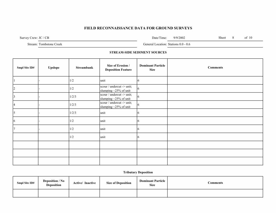
Survey Crew: JC / CB Date/Time: 9/9/2002
Stream: Tombstone Creek General Location: Stations 0.0 - 0.6
Smpl Site ID# Upslope Streambank Size of Erosion / Deposition Feature
Dominant Particle Size
1 - 1/2 unit 6
2 - 1/2 scour / undercut -> unit; slumping ~25% of unit 6
3 - 1/2/3 scour / undercut -> unit; slumping ~25% of unit 6
4 - 1/2/3 scour / undercut -> unit; slumping ~25% of unit 6
5 - 1/2/3 unit 6
6 - 1/2 unit 6
7 - 1/2 unit 6
1/2 unit 6
Smpl Site ID# Deposition / No
Deposition Active/ Inactive Size of Deposition Dominant Particle Size
Sheet 8 of 10
FIELD RECONNAISSANCE DATA FOR GROUND SURVEYS
Comments
Tributary Deposition
STREAM-SIDE SEDIMENT SOURCES
Comments

Survey Crew: Date/Time: Sheet of
Stream: General Location:
Smpl Site ID# Presence / Absence Low Flow BF FP Geomorphic Function Recruitment Potential
(High / Moderate / Low)Comments
missing data sheet
FIELD RECONNAISSANCE DATA FOR GROUND SURVEYS
LARGE WOODY DEBRIS
Channel Zone

Date/Time: 8/20/2002 Sheet 2 of 10
General Location:
Smpl Site ID# GPS LOG ID# Station (estimated in
field) Station (corrected) NORTHING WESTING Feature Comments
1 1 1.06 37 16.450 118 57.147 SS#1 in A1a+/A2a+
2 1.02 37 16.459 118 57.180
2 3 1 37 16.455 118 57.184 SS#2 in A2a+ -> Start Survey Segment
4 0.95 37 16.466 118 57.230 End of survey segment in A1a+/A2a+
5 0.85 37 16.524 118 57.319 Potential reach break from A1a+/A2a+ to ? -> gradient decreases to ~10%
6 0.81 37 16.525 118 57.361
3 7 0.82 37 16.529 118 57.348 Gradient increases from ~10% -> ? ~50' upstream of WP Site upper reach site E
8 0.75 37 16.551 118 57.412 Gradient increases significantly to ~30% (A1a+)
9 0.7 37 16.560 118 57.445
10 0.66 37 16.534 118 57.500 Potential reach break from A/B type segment - lower gradient.
4 11 0.67 37 16.565 118 57.462 SS#4
12 0.65 37 16.564 118 57.487 Downstream end of A2a+ -> Start survey segment at BM-1 - BD Site C
13 0.647 37 16.550 118 57.501 Channel splits -> flow ~50% in northern channel and 50% in southern channel
5 14 0.645 37 16.568 118 57.500 North channel ~50' downstream of split (Headcut Location)
15 0.6 ? 37 16.543 118 57.625 Footbridge crossing on Tombstone
WP Study Site - Site C - Within lower gradient, B-type channel, energy dissipation zone
Surface flow in channel decreases significantly somewhere between 0.81 - 0.85. Alluvial bed with gravel/sand
Downstream end of A1a+ reach -> potential reach break - Start Survey Segment. Pool at base of A1a+~ 100% sand
GPS LOG
Survey Crew:
Stream:
FIELD RECONNAISSANCE DATA FOR GROUND SURVEYS
JC/JH/CB
Tombstone Creek Station 0.6 - 1.1
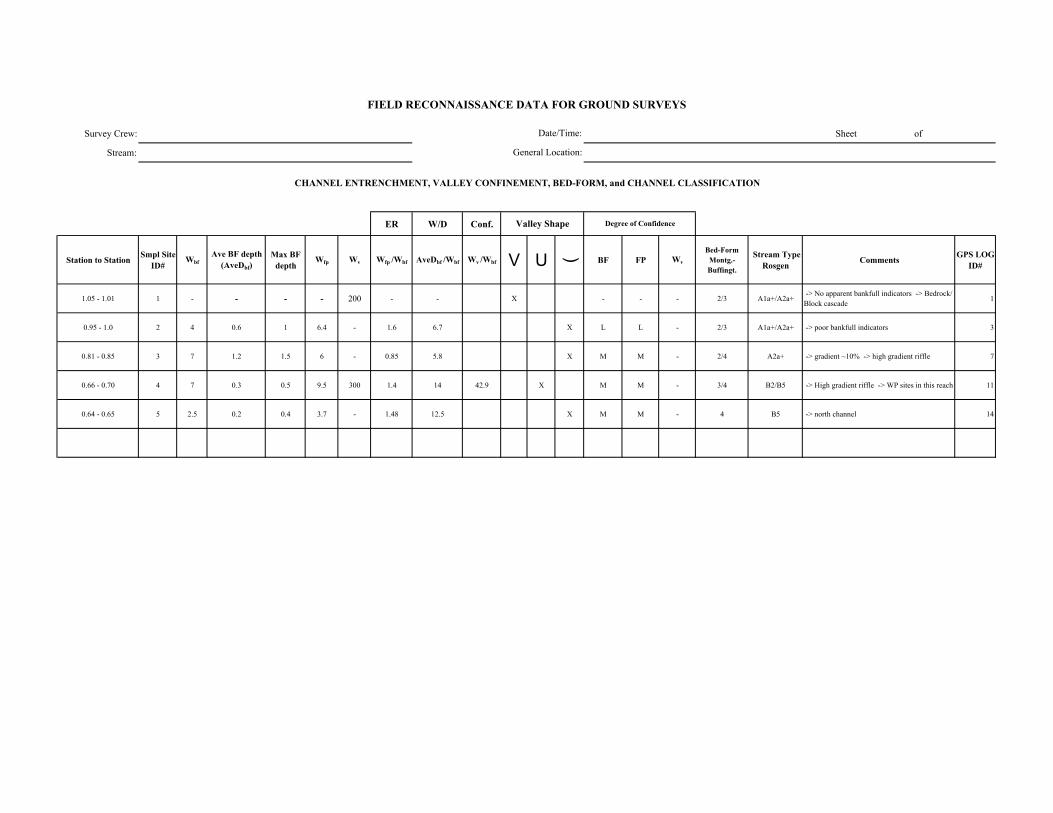
Survey Crew: Sheet of
Stream:
ER W/D Conf.
Station to Station Smpl Site ID#
WbfAve BF depth
(AveDbf)Max BF
depthWfp Wv Wfp /Wbf AveDbf /Wbf Wv /Wbf V U ( BF FP Wv
Bed-Form Montg.-Buffingt.
Stream Type Rosgen Comments GPS LOG
ID#
1.05 - 1.01 1 - - - - 200 - - X - - - 2/3 A1a+/A2a+ -> No apparent bankfull indicators -> Bedrock/ Block cascade 1
0.95 - 1.0 2 4 0.6 1 6.4 - 1.6 6.7 X L L - 2/3 A1a+/A2a+ -> poor bankfull indicators 3
0.81 - 0.85 3 7 1.2 1.5 6 - 0.85 5.8 X M M - 2/4 A2a+ -> gradient ~10% -> high gradient riffle 7
0.66 - 0.70 4 7 0.3 0.5 9.5 300 1.4 14 42.9 X M M - 3/4 B2/B5 -> High gradient riffle -> WP sites in this reach 11
0.64 - 0.65 5 2.5 0.2 0.4 3.7 - 1.48 12.5 X M M - 4 B5 -> north channel 14
FIELD RECONNAISSANCE DATA FOR GROUND SURVEYS
Degree of Confidence
CHANNEL ENTRENCHMENT, VALLEY CONFINEMENT, BED-FORM, and CHANNEL CLASSIFICATION
Valley Shape
Date/Time:
General Location:
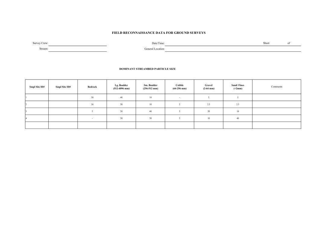
Date/Time:
General Location:
DOMINANT STREAMBED PARTICLE SIZE
Smpl Site ID# Smpl Site ID# Bedrock Lg. Boulder (512-4096 mm)
Sm. Boulder (256-512 mm)
Cobble (64-256 mm)
Gravel (2-64 mm)
Sand/ Fines (<2mm)
1 30 40 10 - 5 5
2 30 50 10 5 2.5 2.5
3 5 20 40 5 20 10
4 - 20 30 5 10 40
Survey Crew:
Stream:
FIELD RECONNAISSANCE DATA FOR GROUND SURVEYS
Sheet of
Comments
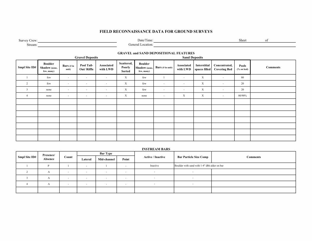
Survey Crew:Stream:
Smpl Site ID# Boulder
Shadow (none, few, many)
Bars (# in unit)
Pool Tail-Out/ Riffle
Associated with LWD
Scattered, Poorly Sorted
Boulder Shadow (none,
few, many)Bars (# in unit)
Associated with LWD
Interstitial spaces filled
Concentrated, Covering Bed
Pools (% on bed)
Comments
1 few - - - X few 1 - X - 80
2 few - - - X few - - X - 20
3 none - - - X few - - X - 20
4 none - - - X none - X X - 80/90%
Lateral Mid-channel Point
1 P 1 - 1 -
2 A - - - -
3 A - - - -
4 A - - - -
Inactive
-
-
-
FIELD RECONNAISSANCE DATA FOR GROUND SURVEYS
Date/Time:General Location:
Sheet of
GRAVEL and SAND DEPOSITIONAL FEATURESGravel Deposits
Smpl Site ID# Comments
Sand Deposits
INSTREAM BARS
Presence/ Absence Count Active / Inactive Bar Particle Size Comp
Bar Type
Boulder with sand with 1-4" dbh alder on bar
-
-
-
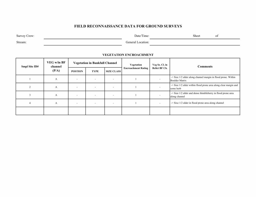
Survey Crew: Date/Time: Sheet of
Stream: General Location:
Vegetation in Bankfull Channel
POSTION TYPE SIZE CLASS
1 A - - - 1 -
2 A - - - 1 -
3 A - - - 1 -
4 A - - - 1 -
Comments
VEGETATION ENCROACHMENT
FIELD RECONNAISSANCE DATA FOR GROUND SURVEYS
Smpl Site ID# VEG w/in BF
channel (P/A)
Vegetation Encroachment Rating
Veg Sz. Cl. in Relict BF Ch.
-> Size 1/2 alder along channel margin in flood prone. Within Boulder Matrix
-> Size 1/2 alder within flood prone area along clear margin and some herb
-> Size 1/2 alder and dense thimbleberry in flood prone area along channel
-> Sixe 1/2 alder in flood prone area along channel

Survey Crew: Date/Time: Sheet of
Stream: General Location:
Smpl Site ID# Erodibility (yes /no)
Bank Composition Instability Feature Causative Erosion Process SCI Stability Rating Comments
1 N 1 - - Stable
2 N 1 - - Stable -> Some isolated areas of bank scour where boulders absent
3 Y 1/2/3 3 2 Vulnerable -> Areas of surface scour and undercut (<50% of channel) where fines present
-> overall rootmass and large material provide stability
4 Y 1/2/3 3 2 Vulnerable -> overall rootmass and large material provide stability
FIELD RECONNAISSANCE DATA FOR GROUND SURVEYS
BANK STABILITY

Survey Crew: Date/Time:
Stream: General Location:
Smpl Site ID# Upslope Streambank Size of Erosion / Deposition Feature
Dominant Particle Size
1 4 - 50% unit 6
2 4 - unit 6
3 4 1/2 - Bank < 50% unit - upslope - unit 6
4 - 1/2 < 50% unit 6
Smpl Site ID# Deposition / No
Deposition Active/ Inactive Size of Deposition Dominant Particle Size
Sheet of
FIELD RECONNAISSANCE DATA FOR GROUND SURVEYS
Comments
Tributary Deposition
STREAM-SIDE SEDIMENT SOURCES
Comments
- upslope - sand/ organic material primarily on right bank - leftbank bedrock (steep slopes) - upslope - sand/ organic material primarily on right bank - leftbank bedrock (steep slopes)
upslope - organic material/sand
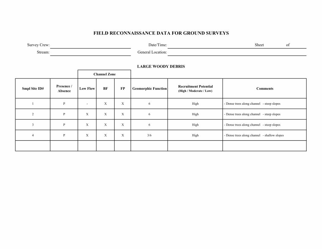
Survey Crew: Date/Time: Sheet of
Stream: General Location:
Smpl Site ID# Presence / Absence Low Flow BF FP Geomorphic Function Recruitment Potential
(High / Moderate / Low)Comments
1 P - X X 6 High - Dense trees along channel - steep slopes
2 P X X X 6 High - Dense trees along channel - steep slopes
3 P X X X 6 High - Dense trees along channel - steep slopes
4 P X X X 3/6 High - Dense trees along channel - shallow slopes
FIELD RECONNAISSANCE DATA FOR GROUND SURVEYS
LARGE WOODY DEBRIS
Channel Zone
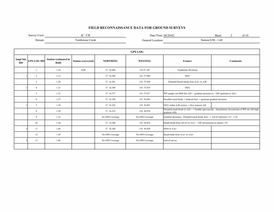
Date/Time: 08/20/02 Sheet 2 of 10
General Location:
Smpl Site ID# GPS LOG ID# Station (estimated in
field) Station (corrected) NORTHING WESTING Feature Comments
1 1.10 0.98 37 16.448 118 57.107 Tombstone Diversion
1 2 1.15 37 16.396 118 57.086 SS#1
3 1.20 37 16.381 118 57.020 Potential Reach break from A1a+ to A/B
2 4 1.21 37 16.380 118 57.018 SS#2
5 1.23 37 16.377 118 57.017 WP sample site BMI Site AD -> gradient increases to ~100' upstream to A2a+
6 1.27 37 16.350 118 56.983 Possible reach break -> bedrock bed -> upstream gradient increases
3 7 1.28 37 16.342 118 56.991 SS#3 within A/B section -> flow transect AD
8 1.30 37 16.333 118 56.976
9 1.32 No GPS Coverage No GPS Coverage Gradient decreases - Potential reach break A2a+ -> A4/A5 between 1.32 - 1.34
10 1.36 37 16.306 118 56.926 Reach break from A4/A5 to A1a+ ~ 100' downstream at station 1.34
4 11 1.46 37 16.268 118 56.850 SS#4 in A1a+
12 1.50 No GPS Coverage No GPS Coverage Reach bank from A1a+ to A2a+
5 13 1.60 No GPS Coverage No GPS Coverage End of survey
FIELD RECONNAISSANCE DATA FOR GROUND SURVEYS
JC / CB
Tombstone Creek Station 0.98 - 1.60
Potential reach break to A2a+ -> boulder jam/cascade - Immediately downstream of WP site AD high gradient riffle
GPS LOG
Survey Crew:
Stream:

Survey Crew: JC/CB/JH ####### Sheet 3 of 10
Stream: Tombstone Creek U/S of Diversion
ER W/D Conf.
Station to Station Smpl Site ID#
WbfAve BF depth
(AveDbf)Max BF
depthWfp Wv Wfp /Wbf AveDbf /Wbf Wv /Wbf V U ( BF FP Wv
Bed-Form Montg.-Buffingt.
Stream Type Rosgen Comments GPS
LOG ID#
1.1 - 1.15 1 - - - - 100+ - - - X - - - - - 3 A1a+ - No apparent bankfull indicators - entrenched channel 1
1.20 - 1.25 2a 5 0.8 1 7.8 - 1.56 6.25 - - - X H H - 4 A2/A5 (B2/B5?) WP site does not appear representative flow influenced by LWD 4
2b 3.5 0.8 1 4.3 - 1.22 4.375 - - - X M M - 4 A2/A5 Plane bed area between boulder cascades, flow influenced by LWD
2c 2.5 0.7 0.8 4.5 - 1.8 3.125 - - - X H H - 4 A4/B4? check gradient potential Aa+
1.27 - 1.30 3 5.8 0.6 0.8 7.8 - 1.34 1.34 - - - X H H - 3 A4/A5 Plane bed with LWD jams creating grade stabilization 7
1.4 - 1.46 4 - - - - - - - - - - X - - - 2 A1a+ No apparent bankfull indicators 11
1.50 - 1.60 5 - - - - - - - - - - X - - - 3 A2a+ No apparent bankfull indicators 13
FIELD RECONNAISSANCE DATA FOR GROUND SURVEYS
Degree of Confidence
CHANNEL ENTRENCHMENT, VALLEY CONFINEMENT, BED-FORM, and CHANNEL CLASSIFICATION
Valley Shape
Date/Time:
General Location:
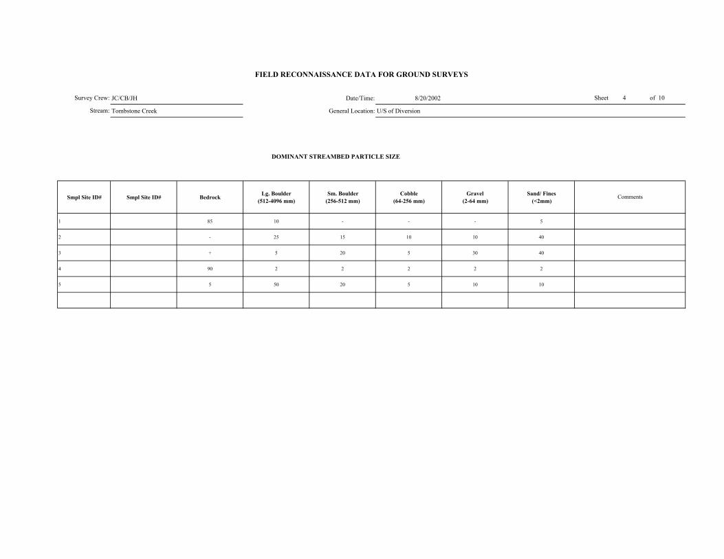
JC/CB/JH Date/Time: 8/20/2002
Tombstone Creek General Location: U/S of Diversion
DOMINANT STREAMBED PARTICLE SIZE
Smpl Site ID# Smpl Site ID# Bedrock Lg. Boulder (512-4096 mm)
Sm. Boulder (256-512 mm)
Cobble (64-256 mm)
Gravel (2-64 mm)
Sand/ Fines (<2mm)
1 85 10 - - - 5
2 - 25 15 10 10 40
3 + 5 20 5 30 40
4 90 2 2 2 2 2
5 5 50 20 5 10 10
FIELD RECONNAISSANCE DATA FOR GROUND SURVEYS
Comments
Stream:
Sheet 4 of 10Survey Crew:
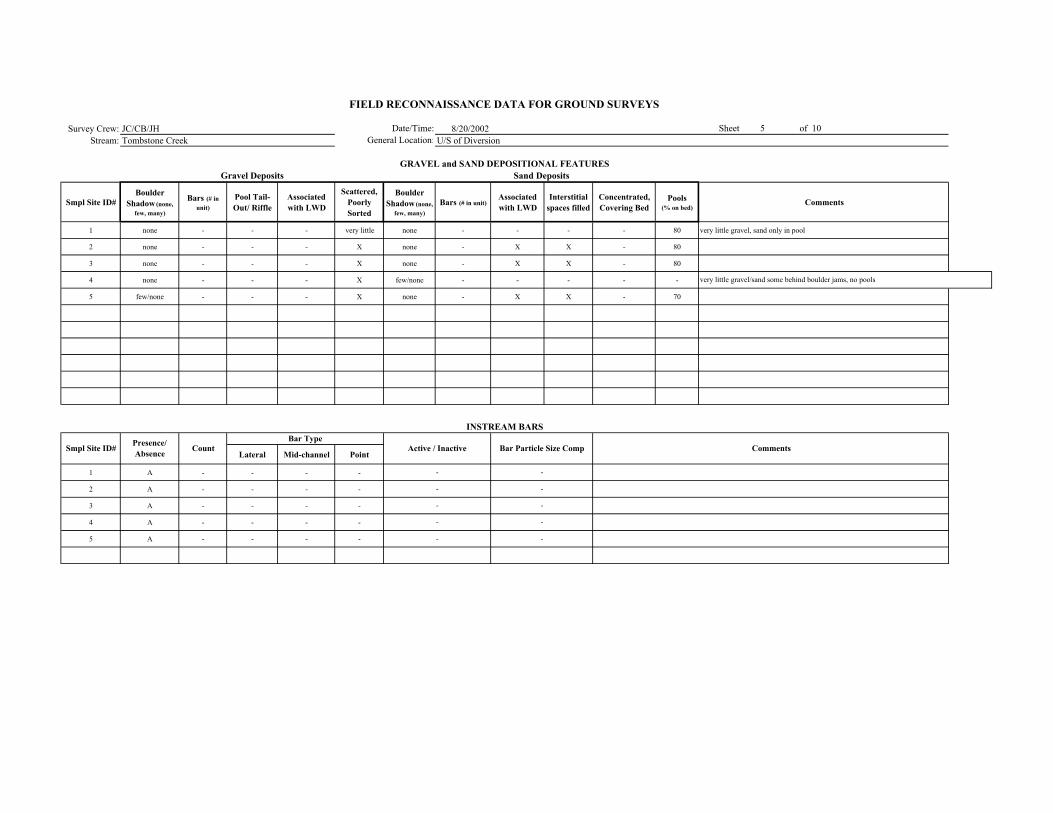
Survey Crew: JC/CB/JH 8/20/2002Stream: Tombstone Creek U/S of Diversion
Smpl Site ID# Boulder
Shadow (none, few, many)
Bars (# in unit)
Pool Tail-Out/ Riffle
Associated with LWD
Scattered, Poorly Sorted
Boulder Shadow (none,
few, many)Bars (# in unit)
Associated with LWD
Interstitial spaces filled
Concentrated, Covering Bed
Pools (% on bed)
Comments
1 none - - - very little none - - - - 80 very little gravel, sand only in pool
2 none - - - X none - X X - 80
3 none - - - X none - X X - 80
4 none - - - X few/none - - - - -
5 few/none - - - X none - X X - 70
Lateral Mid-channel Point
1 A - - - -
2 A - - - -
3 A - - - -
4 A - - - -
5 A - - - -
-
-
-
-
-
-
-
-
-
-
FIELD RECONNAISSANCE DATA FOR GROUND SURVEYS
Date/Time:General Location:
Sheet 5 of 10
GRAVEL and SAND DEPOSITIONAL FEATURESGravel Deposits
Smpl Site ID# Comments
Sand Deposits
INSTREAM BARS
Presence/ Absence Count Active / Inactive Bar Particle Size Comp
Bar Type
very little gravel/sand some behind boulder jams, no pools
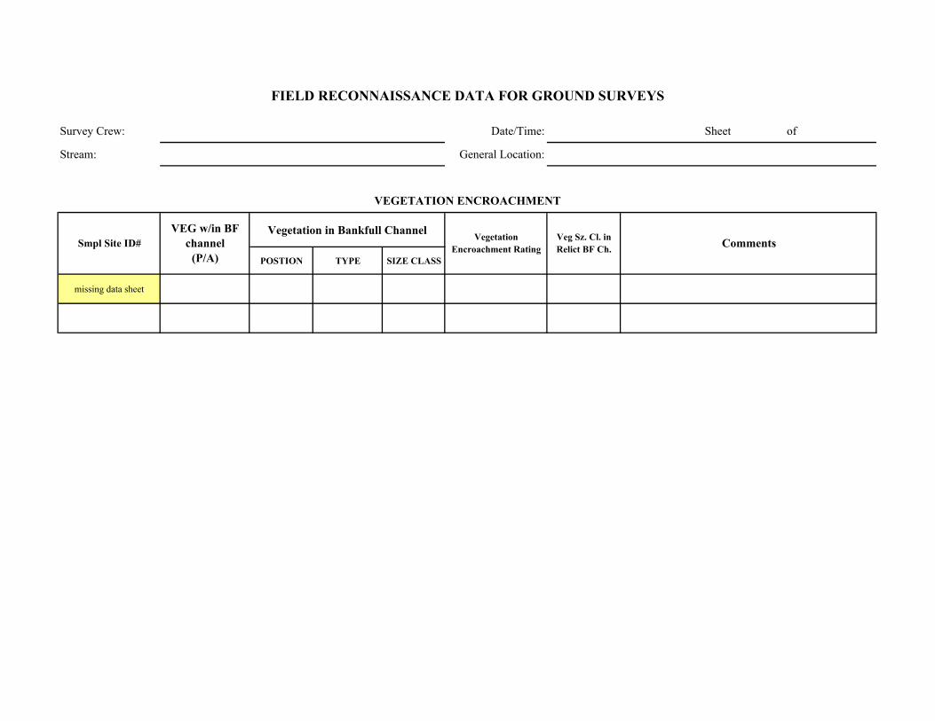
Survey Crew: Date/Time: Sheet of
Stream: General Location:
Vegetation in Bankfull Channel
POSTION TYPE SIZE CLASS
missing data sheet
Comments
VEGETATION ENCROACHMENT
FIELD RECONNAISSANCE DATA FOR GROUND SURVEYS
Smpl Site ID# VEG w/in BF
channel (P/A)
Vegetation Encroachment Rating
Veg Sz. Cl. in Relict BF Ch.
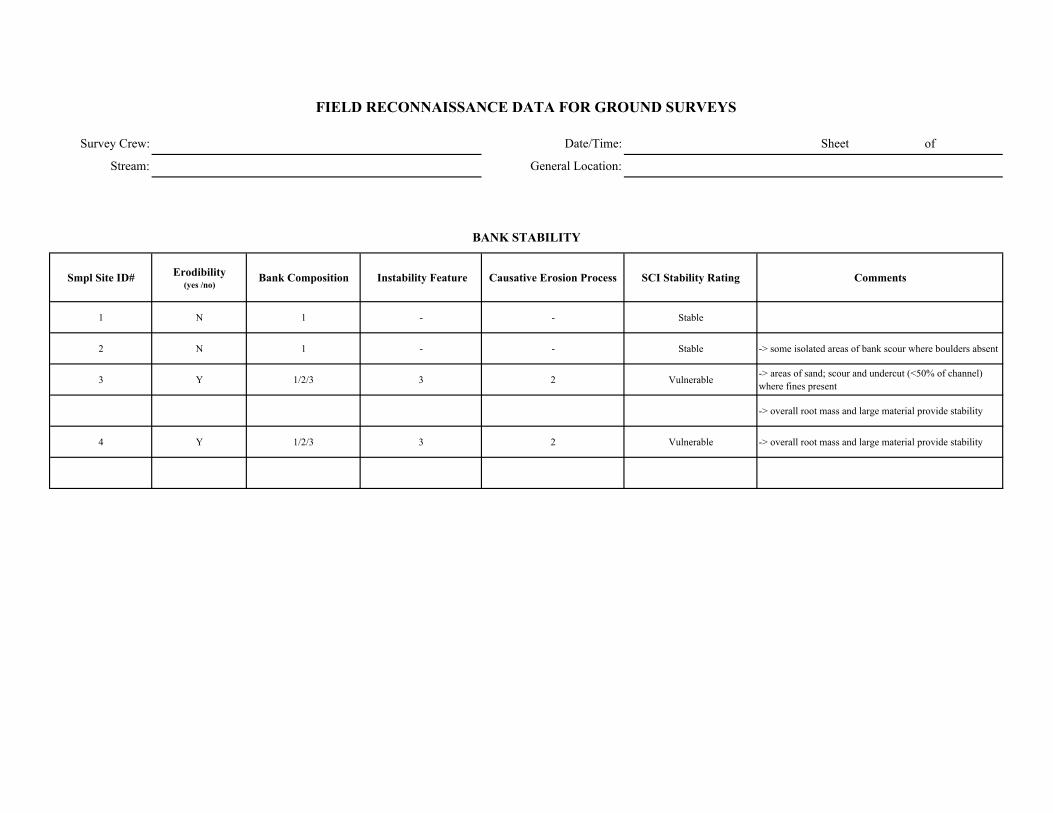
Survey Crew: Date/Time: Sheet of
Stream: General Location:
Smpl Site ID# Erodibility (yes /no)
Bank Composition Instability Feature Causative Erosion Process SCI Stability Rating Comments
1 N 1 - - Stable
2 N 1 - - Stable -> some isolated areas of bank scour where boulders absent
3 Y 1/2/3 3 2 Vulnerable -> areas of sand; scour and undercut (<50% of channel) where fines present
-> overall root mass and large material provide stability
4 Y 1/2/3 3 2 Vulnerable -> overall root mass and large material provide stability
FIELD RECONNAISSANCE DATA FOR GROUND SURVEYS
BANK STABILITY

Survey Crew: Date/Time:
Stream: General Location:
Smpl Site ID# Upslope Streambank Size of Erosion / Deposition Feature
Dominant Particle Size
1 4 - unit 6
2 4 1/2 unit 6
3 4 1/2 unit 6
4 4 - 50% unit 6
5 4 - unit 6
Smpl Site ID# Deposition / No
Deposition Active/ Inactive Size of Deposition Dominant Particle Size
- upslope -> sand/ organic material
Sheet of
FIELD RECONNAISSANCE DATA FOR GROUND SURVEYS
Comments
Tributary Deposition
STREAM-SIDE SEDIMENT SOURCES
Comments
- upslope sand/organic material - sporadic rockfalls along channel
- upslope -> sand/ organic material
- upslope -> sand/ organic material
- upslope -> sand/ organic material

Survey Crew: Date/Time: Sheet of
Stream: General Location:
Smpl Site ID# Presence / Absence Low Flow BF FP Geomorphic Function Recruitment Potential
(High / Moderate / Low)Comments
1 P X X X 3/6 High -> Alders growing across channel -> LWD ~ 4-6". Abundant small woody debris in channel and banks. -> Steep slopes dense conifers along channel
2 P X X X 1/3/6 High -> Dense conifers along channel, low slope
3 P X X X 1/3/6 High -> Dense conifers along channel, low slope -> Abundant LWD in channel
4 A - - - - Low - Moderate -> Sparse conifers but high potential where present
5 P X X X 3/6 High -> Abundant trees along channel
FIELD RECONNAISSANCE DATA FOR GROUND SURVEYS
LARGE WOODY DEBRIS
Channel Zone


