13
READ AND SAVE THESE INSTRUCTIONS CEILING FANS INSTALLATION INSTRUCTION MODEL SERIES LTG-CF7007
READ AND SAVE THESE INSTRUCTIONS
CEILING FANSINSTALLATION INSTRUCTION
MODEL SERIES
LTG-CF7007
Before beginning installation of your new ceiling fan, read and follow these safety precautions. If you are not familiar with national and local electrical codes and basic electrical wiring procedures, we recommend that you have a qualified electrician install your new ceiling fan.
Before you begin, TURN OFF THE ELECTRICITY. Determine which circuit your new fan will be using and remove the fuse or turn off the circuit breaker at the main electrical panel.
Make sure that all wiring conforms to national and local electrical codes. If you are in question, obtain a copy of the codes and wire the fan accordingly. Never leave bare wires uncovered (wire connection), use wire nuts to cap all connections. Plastic electri-cal tape is not recommended.
When working with electricity, never take short cuts. Follow the code in every respect. Basic requirements for a ceiling fan installed with lights are, 120 volts AC - 60Hz, on a grounded circuit with a 15 amp breaker or fuse. Make sure that your electrical system and choice of location meet these requirements.
If the location where you plan to install your fan does not already have an electrical outlet, hire a licensed electrician to run the wiring and install an outlet box designed for ceiling fans or heavy fixtures. The outlet box should be able to support a mini-mum moving weight of 50 pounds and marked “Acceptable for Fan Support” (Plastic outlet boxes are not recommended for ceiling fan installation).
If you plan to use an existing electrical location, check to make sure that the outlet box is not PLASTIC, that it is securely attached and able to support at least 50 pounds of moving weight and marked “Acceptable for Fan Support”. If you have any questions, outlet boxes and support systems for ceiling fans are available at most hardware and do-it-yourself centers. In most cases, your dealer will have all the necessary products for the proper and safe installation of your ceiling fan.
The location you choose should have a minimum clearance of 20 inches from any wall to the blade tip at any point in its rotation and a minimum of 7 feet from blade level to floor and 10 inches from the blades.
1
SAFETY PRECAUTIONS
2
This ceiling fan was not designed for installation in any location where it might be exposed to moisture or high humidity. Installation in this type of location could be UNSAFE, will most likely damage the fan and its finish... and will VOID YOUR WARRANTY.
Every effort has been made to provide you with proper instructions for the safe installation of this ceiling fan. You could however, encounter situations or problems not covered in this manual. Should this occur, please refer to a do-it-yourself wiring handbook or hire a qualified electrician to install your fan.
Never attach the blades to your ceiling fan before the fan body is properly mounted on the ceiling.
Lubrication of your new ceiling fan is not necessary. The ball bearings have been adequately charged with grease and permanently sealed at the factory so that, under normal conditions, further attention is not necessary.
To reduce the risk of fire, electrical shock, or personal injury, mount this fan to an outlet box marked “Acceptable for Fan Support” and use the Mounting Screws provided with the outlet box. CAUTION: Install the primary mounting means and use only the hardware provided with the fan.
To reduce the risk of personal injury take care not to bend the blade carriers. Be careful not to insert foreign objects into rotating fan blades.
The important safeguards and instructions appearing in this manual are not meant to cover all possible conditions and situations that may occur. It must be understood that common sense, caution and careful attention to detail are factors which cannot be built into this product. These factors must be supplied by the person or persons installing, caring for, and operating the unit.
Look at Me!I have safety Tips andIdeas for installation
These instructions are designed for a number of similar but different ceiling fans. As you proceed, some steps may or may not apply to the fan you purchased. Compare each step or optional procedure to your fan and proceed accordingly.
WARNING
WARNING
WARNING
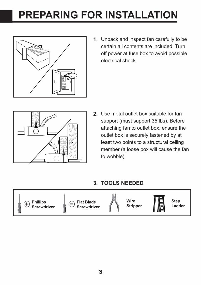
Unpack and inspect fan carefully to be certain all contents are included. Turn off power at fuse box to avoid possible electrical shock.
3
Use metal outlet box suitable for fan support (must support 35 lbs). Before attaching fan to outlet box, ensure the outlet box is securely fastened by at least two points to a structural ceiling member (a loose box will cause the fan to wobble).
PREPARING FOR INSTALLATION
Phillips Screwdriver + Flat Blade
Screwdriver- Step Ladder
Wire Stripper
1.
2.
TOOLS NEEDED3.

Install the mounting bracket onto the electrical junction box in the ceiling using two machine screws, two wash-ers and two lock washers.
4
The mounting bracket has slotted holes to enable it to move sideways for proper alignment. Make sure the mounting bracket is centered over the electrical junction box and that it is securely attached. Pull the electrical wires in the junction box down and through the mounting bracket. Loosen the two canopy mounting screws on the downside face of the mounting bracket. Back them out about half way. This will allow for easier installa-tion of the ceiling canopy later.
Note: Angle mount best suited for angled or vaulted ceilings. A longer downrod is sometimes necessary to ensure proper blade clearance.Ensure the ceiling angle is not steeper than 16 degrees. Hanger opening must be facing up-side.
INSTALL MOUNTING BRACKET
1.
2.
3.
Slotted
Junction Box
Ceiling Canopy Mounting Screw
NO MOVEMENT SHOULD OCCUR BETWEEN THE MOUNTING BRACKET AND THE ELECTRICAL JUNCTION BOX.
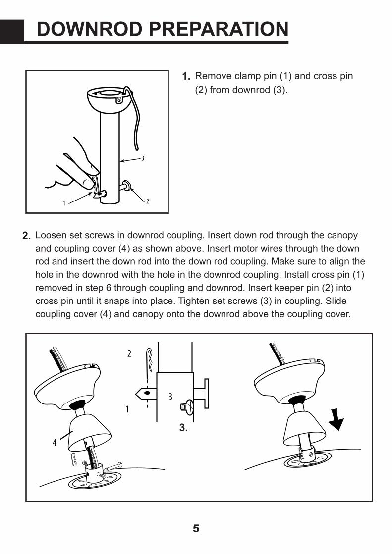
Remove clamp pin (1) and cross pin (2) from downrod (3).
5
Loosen set screws in downrod coupling. Insert down rod through the canopy and coupling cover (4) as shown above. Insert motor wires through the down rod and insert the down rod into the down rod coupling. Make sure to align the hole in the downrod with the hole in the downrod coupling. Install cross pin (1) removed in step 6 through coupling and downrod. Insert keeper pin (2) into cross pin until it snaps into place. Tighten set screws (3) in coupling. Slide coupling cover (4) and canopy onto the downrod above the coupling cover.
DOWNROD PREPARATION
1.
2.
3.
1 2
3
1
4
3
2
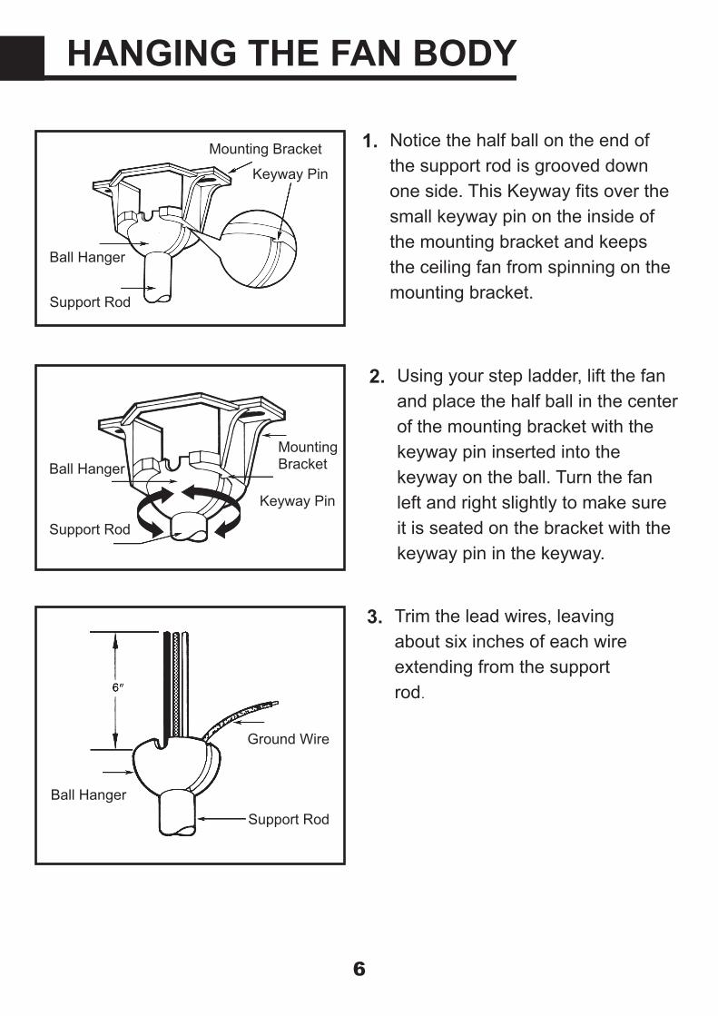
Notice the half ball on the end of the support rod is grooved down one side. This Keyway fits over the small keyway pin on the inside of the mounting bracket and keeps the ceiling fan from spinning on the mounting bracket.
6
Using your step ladder, lift the fan and place the half ball in the center of the mounting bracket with the keyway pin inserted into the keyway on the ball. Turn the fan left and right slightly to make sure it is seated on the bracket with the keyway pin in the keyway.
HANGING THE FAN BODY
1.
2.
Trim the lead wires, leaving about six inches of each wire extending from the support rod.
3.
Mounting Bracket
Keyway Pin
Ball Hanger
Support Rod
MountingBracket
Keyway Pin
Ball Hanger
Support Rod
Ground Wire
Support RodBall Hanger

Use wire connnectors to connect household supply and receiver wires according to the diagram and the following steps:• Connect the green wire from the downrod and mounting bracket to the Bare/Green (ground) supply wire.• Connect the Blue wire with the white label to the blue fan wire.• Connect the Black wire with the white label to the black fan wire.• Connect the White wire with the white label to the white fan wire.• Connect the Red wire with the red label to the Black (live) supply wire.• Connect the White wire with the red label to the White (neutral) supply wire.
7
WIRE CONNECTION
1.Black (hot/power)
White (neutral)
Bare/Green(ground)
Red
Whi
te
White White
BlackBlue Blue
Black
Green
Green
Rec
eive
r
WARNING: Do not wire the fan motor to a variable-speed (dimmer) wall control.
Lift the ceiling canopy up into place covering the mounting bracket. Push the cannopy up so the screws come through the mounting holes in in the cannopy. Rotate the canopy slightly and tighten the screws.
2.
Please refer to page 9~10 for remote controller and receiver installation and operation detail.
Mounting Bracket
Canopy
Canopy Screw

Remove the two screws from the covering plate of blade-fixing hole. Insert blades one at a time through four slots around the canopy and secure with three screws for each blade through the top opening. Repeat this procedure for all blades. Replace the cover plate and secure with two screws one all four blades have been firmly fitted. Please ensure that the blades do not get bent during the installation process while the fan may be on the ground, as this will affect the perfor-mance and balance of the fan and this is NOT covered under warranty.
8
Always ensure that fan is set to "OFF" and blades are still prior to changing direction of blades. Reverse switch on fan should ideally be set on "FOR-WARD" (left position) during warmer seasons to move blades in an anticiock-wise direction & "RVERSE" (right posi-tion) during our coaler seasons to make the fan rotate in a clockwise direction.
BLADES INSTALLATION
1.
2.
Place bulb ( included) with fan into the socket on the light kit, Place glass shade on light kit and rotate until secure.Tip: Dimmable LED bulbs can use the dimmer function.
3.
9
Use wire connecting nuts supplied with the fan
(FIG.3)
FROM POWER SOURCE AC 110~120 VOLT 60Hz 3.5AMPS.
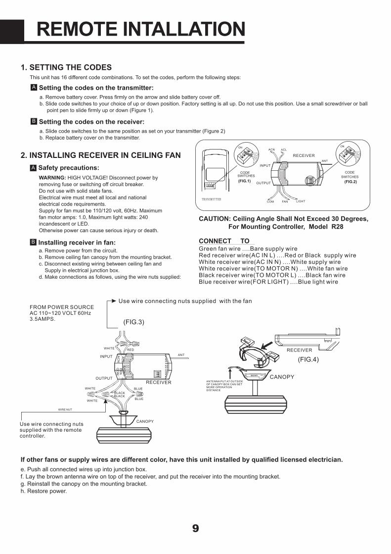
CONNECT TOGreen fan wire ....Bare supply wireRed receiver wire(AC IN L) ....Red or Black supply wireWhite receiver wire(AC IN N) ....White supply wireWhite receiver wire(TO MOTOR N) ....White fan wireBlack receiver wire(TO MOTOR L) ....Black fan wireBlue receiver wire(FOR LIGHT) ....Blue light wire
CAUTION: Ceiling Angle Shall Not Exceed 30 Degrees,For Mounting Controller, Model R28
ACN ACL
ANT
COM FAN LIGHTTRANSMITTER
CODESWITCHES(FIG.1) (FIG.2)
SWITCHESCODE
ON
1 2 3 4
ON 23
4
1
ON
ON2
34
1
ON
INPUT
OUTPUT
RECEIVER
WHITE
LC
AAC
N
INPUT
OUTPUT
RED
FAN
LIGH
T
BLUE
ANT
CANOPY
BLUE
CO
M
BLACKWHITE
WHITEBLACK
Use wire connecting nuts supplied with the remote controller.
WIRE NUT
RECEIVER
RECEIVER
CANOPY
(FIG.4)
ANTENNA PUT AT OUTSIDE OF CANOPY BOX CAN GET MORE OPERATION DISTANCE
1. SETTING THE CODESThis unit has 16 different code combinations. To set the codes, perform the following steps:
Setting the codes on the transmitter:A
a. Remove battery cover. Press firmly on the arrow and slide battery cover off.b. Slide code switches to your choice of up or down position. Factory setting is all up. Do not use this position. Use a small screwdriver or ball point pen to slide firmly up or down (Figure 1).
Setting the codes on the receiver:B
a. Slide code switches to the same position as set on your transmitter (Figure 2)b. Replace battery cover on the transmitter.
2. INSTALLING RECEIVER IN CEILING FANSafety precautions:A
WARNING: HIGH VOLTAGE! Disconnect power byremoving fuse or switching off circuit breaker.Do not use with solid state fans.Electrical wire must meet all local and nationalelectrical code requirements.Supply for fan must be 110/120 volt, 60Hz. Maximumfan motor amps: 1.0, Maximum light watts: 240incandescent or LED.Otherwise power can cause serious injury or death.
Installing receiver in fan:Ba. Remove power from the circuit.b. Remove ceiling fan canopy from the mounting bracket.c. Disconnect existing wiring between ceiling fan and Supply in electrical junction box.d. Make connections as follows, using the wire nuts supplied:
If other fans or supply wires are different color, have this unit installed by qualified licensed electrician.e. Push all connected wires up into junction box.f. Lay the brown antenna wire on top of the receiver, and put the receiver into the mounting bracket.g. Reinstall the canopy on the mounting bracket.h. Restore power.
REMOTE INTALLATION
10
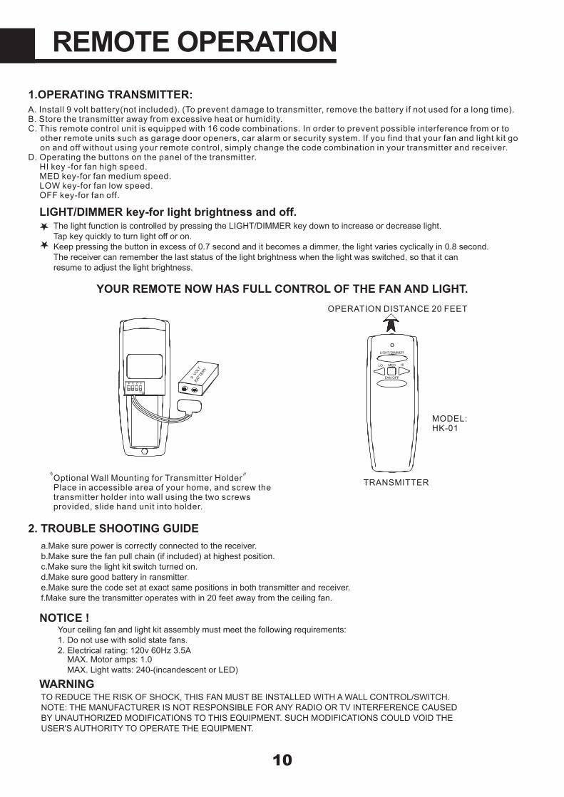
1.OPERATING TRANSMITTER:A. Install 9 volt battery(not included). (To prevent damage to transmitter, remove the battery if not used for a long time). B. Store the transmitter away from excessive heat or humidity.
C. This remote control unit is equipped with 16 code combinations. In order to prevent possible interference from or to other remote units such as garage door openers, car alarm or security system. If you find that your fan and light kit go
on and off without using your remote control, simply change the code combination in your transmitter and receiver. D. Operating the buttons on the panel of the transmitter.
HI key -for fan high speed.MED key-for fan medium speed.
LOW key-for fan low speed. OFF key-for fan off.
YOUR REMOTE NOW HAS FULL CONTROL OF THE FAN AND LIGHT.
FAN OFF
LO HIMED
LIGHT/DIMMER
OPERATION DISTANCE 20 FEET
TRANSMITTER
MODEL:HK-01
Optional Wall Mounting for Transmitter HolderPlace in accessible area of your home, and screw the transmitter holder into wall using the two screws provided, slide hand unit into holder.
2. TROUBLE SHOOTING GUIDE
NOTICE !
ON
1 2 3 4 BATT
ERY
9 VO
LT
WARNING
a.Make sure power is correctly connected to the receiver.b.Make sure the fan pull chain (if included) at highest position.c.Make sure the light kit switch turned on.d.Make sure good battery in ransmitter.e.Make sure the code set at exact same positions in both transmitter and receiver.f.Make sure the transmitter operates with in 20 feet away from the ceiling fan.
The light function is controlled by pressing the LIGHT/DIMMER key down to increase or decrease light.Tap key quickly to turn light off or on.Keep pressing the button in excess of 0.7 second and it becomes a dimmer, the light varies cyclically in 0.8 second.The receiver can remember the last status of the light brightness when the light was switched, so that it canresume to adjust the light brightness.
LIGHT/DIMMER key-for light brightness and off.
Your ceiling fan and light kit assembly must meet the following requirements:1. Do not use with solid state fans.2. Electrical rating: 120v 60Hz 3.5A
MAX. Motor amps: 1.0MAX. Light watts: 240-(incandescent or LED)
TO REDUCE THE RISK OF SHOCK, THIS FAN MUST BE INSTALLED WITH A WALL CONTROL/SWITCH.NOTE: THE MANUFACTURER IS NOT RESPONSIBLE FOR ANY RADIO OR TV INTERFERENCE CAUSEDBY UNAUTHORIZED MODIFICATIONS TO THIS EQUIPMENT. SUCH MODIFICATIONS COULD VOID THEUSER'S AUTHORITY TO OPERATE THE EQUIPMENT.
REMOTE OPERATION
11
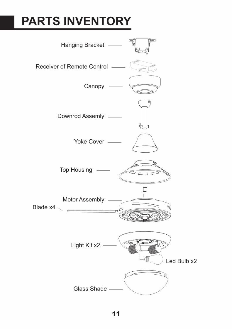
PARTS INVENTORY
Canopy
Light Kit x2
Receiver of Remote Control
Hanging Bracket
Downrod Assemly
Yoke Cover
Top Housing
Motor Assembly
Glass Shade
Blade x4
Led Bulb x2
Check circuit fuses or breakers.Check all electrical connections to insure propercontact.CAUTION: Make sure the main power if OFF when checking any electrical connection.
12
1. Fan will not start:
Make sure all motor housing screws are sung.Make sure the screws that attach the fan blade brackets to the motor are tight.Make sure wire nut connections are not rubbing against each other or the interior wall of the switch housing. CAUTION: Make sure main power is off.Allow a 24-hour "breaking-in" period. Most noise associated with a new fan disappear during this time.If using an optional light kit, make sure the screws securing the glassware are tight. Make sure the light bulbs are not touchingany other component.
2. Fan sounds noisy:
Check that all blade and blade arm screws are secure.Most fan wobbling problems are caused by blade levels unequal. Check this level by selecting a point on the ceiling above the tip of one of the blades. Measure this distance. Rotate the fan until the next blade is positioned for measurement. Repeat for each blade. This distance deviation should be equal within 1/8".Use the enclosed Blade Balancing Kit if the blade wobble is still noticeable.If the blade wobble is still noticeable, interchanging two adjacent ( side by side) blades can reditribute the weight and possibly result in smoother operation.
3. Fan wobble:
PROBLEM SOLUTION
1.2.3.
4.
5.
1.2.
3.
4.
1.2.


