Centrifugal Pump with Volute Casing Original Operating Manual ALLHEAT Series ® N..WH, C..WH Version BA-2014.02 ID-No. 550 407 VM-No. 460.0028 GB ALLWEILER GmbH Postfach 1140 Allweilerstr. 1 78301 Radolfzell Germany Phone: +49 (0) 7732-86-0 Fax: +49 (0) 7732-86-436 E-mail: [email protected]Internet: http://www.allweiler.com We reserve the right to make technical changes. Read carefully before use. Save for future use.
• Describes safe and appropriate operation during all oper-ating phases
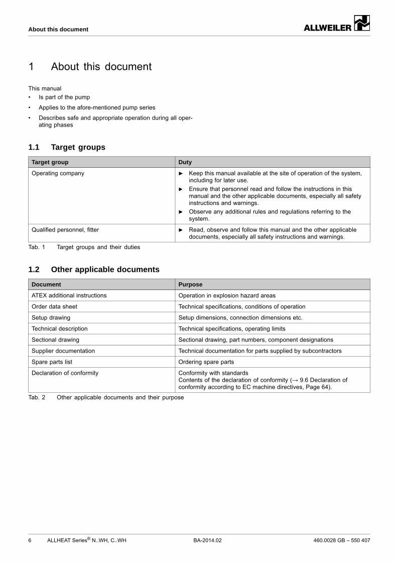
1.1 Target groups
Target group Duty
Operating company Keep this manual available at the site of operation of the system,including for later use.
Ensure that personnel read and follow the instructions in thismanual and the other applicable documents, especially all safetyinstructions and warnings.
Observe any additional rules and regulations referring to thesystem.
Qualified personnel, fitter Read, observe and follow this manual and the other applicabledocuments, especially all safety instructions and warnings.
Tab. 1 Target groups and their duties
1.2 Other applicable documents
Document Purpose
ATEX additional instructions Operation in explosion hazard areas
Order data sheet Technical specifications, conditions of operation
Setup drawing Setup dimensions, connection dimensions etc.
Sectional drawing Sectional drawing, part numbers, component designations
Supplier documentation Technical documentation for parts supplied by subcontractors
Spare parts list Ordering spare parts
Declaration of conformity Conformity with standardsContents of the declaration of conformity (→ 9.6 Declaration ofconformity according to EC machine directives, Page 64).
Tab. 2 Other applicable documents and their purpose
The manufacturer does not accept any liability caused bydisregarding the entire documentation.
2.1 Intended use
• Only use the pump for pumping the agreed pumped media(→ order data sheet).
• Adhere to the operating limits and size-dependent mini-mum flow rate.
• Avoid dry running:Initial damage, such as destruction of the mechanical sealand plastic parts, will occur within only a few seconds.– Make sure the pump is only operated with, and never
without, a pumped medium.
• Avoid cavitation:– Fully open the suction-side armature and do not use it
to adjust the flow rate.– Do not open the pressure-side armature beyond the
agreed operating point.
• Avoid overheating:– Do not operate the pump while the pressure-side arma-
ture is closed.– Observe the minimum flow rate (→ order data sheet).
• Avoid damage to the motor:– Do not open the pressure-side armature beyond the
agreed operating point.– Note the maximum permissible number of times the
motor can be switched on per hour (→ manufacturer'sspecifications).
• Consult the manufacturer about any other use of the pump.
• When a pump is delivered without a motor, the pump unitmust be completed in accordance with the stipulations ofmachine directive 2006/42/EC.
Prevention of obvious misuse (examples)
• Note the operating limits of the pump concerning temper-ature, pressure, flow rate and motor speed (→ order datasheet).
• The power consumed by the pump increases with increas-ing density of the pumped medium. To avoid overloadingthe pump, coupling or motor, stay within the agreed density(→ order data sheet).Lower densities are allowed. Adapt the auxiliary systemsaccordingly.
• When pumping liquids containing solids, ensure the limitsfor the proportion of solids and the grain size are main-tained (→ order data sheet, technical description).
• When using auxiliary systems, ensure there is a continuoussupply of the appropriate operating medium.
• Pumps used with water as the pumped liquid must not beused for foodstuffs or drinking water. Use of the pump forfoodstuffs or drinking water must be specified in the orderdata sheet.
• Only select the setup type according to this operating man-ual. For example, the following are not allowed:– Hanging base plate pumps in the pipe– Overhead installation– Installation in the immediate vicinity of extreme heat or
cold sources– Installation too close to the wall
2.2 General safety instructions
Take note of the following regulations before carrying outany work.
2.2.1 Product safety
The pump has been constructed according to the latest tech-nology and recognized technical safety rules. Nevertheless,operation of the pump can involve risks to life and health of theuser or third parties and risk of damage to the pump and otherproperty.
• Only operate the pump if it is in perfect technical conditionand only use it as intended, staying aware of safety andrisks, and in adherence to the instructions in this manual.
• Keep this manual and all other applicable documents com-plete, legible and accessible to personnel at all times.
• Refrain from any procedures and actions that wouldexpose personnel or third parties to any risk.
• In the event of any safety-relevant faults, shut down thepump immediately and have the fault corrected by appro-priate personnel.
• In addition to the entire documentation for the product,comply with statutory or other safety and accident-preven-tion regulations and the applicable standards and guide-lines in the country where the pump is operated.
• Only operate the pump if it is in perfect technical conditionand only use it as intended, staying aware of safety andrisks, and in adherence to the instructions in this manual.
• Ensure that the following safety aspects are observed andmonitored:– Adherence to intended use– Statutory or other safety and accident-prevention reg-
ulations– Safety regulations governing the handling of haz-
ardous substances– Applicable standards and guidelines in the country
where the pump is operated
• Make protective equipment available.
Qualified personnel
• Make sure all personnel tasked with work on the pumphave read and understood this manual and all other appli-cable documents, especially the safety, maintenance andrepair information, before they start any work.
• Organize responsibilities, areas of competence and thesupervision of personnel.
• Ensure that all work is carried out by specialist techniciansonly:– Fitting, repair and maintenance work– Work on the electrical system
• Make sure trainee personnel only work on the pump undersupervision of specialist technicians.
Safety equipment
• Provide the following safety equipment and verify its func-tionality:– For hot, cold and moving parts: safety guarding pro-
vided by the customer– For possible build up of electrostatic charge: ensure
appropriate grounding
Warranty
• Obtain the manufacturer's approval prior to carrying outanymodifications, repairs or alterations during the warrantyperiod.
• Only use genuine parts or parts that have been approvedby the manufacturer.
2.2.3 Obligations of personnel
• All directions given on the pumpmust be followed (and keptlegible), e.g. the arrow indicating the direction of rotationand the markings for fluid connections.
• Pump, coupling guard and components:– Do not step on them or use as a climbing aid– Do not use them to support boards, ramps or beams– Do not use them as a fixing point for winches or sup-
ports– Do not use them for storing paper or similar materials– Do not use hot pump or motor components as a heating
point– Do not de-ice using gas burners or similar tools
• Do not remove the safety guarding for hot, cold or movingparts during operation.
• Use protective equipment if necessary.
• Only carry out work on the pump while it is not running.
• Isolate the motor from its supply voltage and keep it lockedin that state when carrying out any fitting or maintenancework.
• Reinstall the safety equipment on the pump as required byregulations after any work on the pump.
2.3 Specific hazards
2.3.1 Explosion hazard area
• (→ ATEX additional instructions).
2.3.2 Hazardous pumped media
• Follow the safety regulations for handling hazardous sub-stances when pumping hazardous(e.g. hot, flammable, poisonous or potentially harmful)media.
• Use protective equipment when carrying out any work onthe pump.
Only one of the following shaft seals can be used.
3.3.1 Mechanical seals
Mechanical seals have functional leaks.
• Single mechanical seal
• Single mechanical seal with quenching
3.4 Auxiliary systems
3.4.1 Sealing systems
Only one of the following sealing systems can be used.
Quenching
1
2 3
Fig. 7 Single mechanical seal with quenching(sketch)
1 Pumped medium
2 Single mechanical seal
3 Sealing medium (unpressurized)
The pressure of the pumped medium is higher than the pres-sure of the sealing medium during quenching. The seal sur-faces are lubricated by the pumped medium.
Application examples:
• Pumped liquids that produce a chemical reaction with air
For pumps in explosion hazard areas (→ ATEX additionalinstructions).
NOTEMaterial damage due to distortion or passage of electricalcurrent in the bearing!
Do not make any structural modifications to the pump unitor pump casing.
Do not carry out any welding work on the pump unit orpump casing.
NOTEMaterial damage caused by dirt!
Do not remove the transport seals until immediately beforesetting up the pump.
Do not remove any covers or transport and sealing coversuntil immediately before connecting the pipes to the pump.
5.1 Preparing the setup
5.1.1 Checking the ambient conditions
Make sure the required ambient conditions are fulfilled(→ 9.3.1 Ambient conditions, Page 56).
5.1.2 Preparing the installation site
1. Ensure the installation site meets the following conditions:– Pump is freely accessible from all sides– Sufficient space for installation/removal of the pipes
and for maintenance and repair work, especially for theremoval and installation of the pump and the motor
– Pump not exposed to external vibrations (damage tobearings)
– Frost protection
2. Ensure that the fan flow from the motor to the pump doesnot encounter any obstacles.
5.1.3 Preparing the foundation and surface
Setup options:– With concrete foundation– With steel foundation frame– Without foundation
Make sure the foundation and surface meet the followingconditions:– Level– Clean (no oil, dust or other impurities)– Foundation and surface can support the weight of the
pump aggregate and all operating forces– Ensure the pump is stable and cannot tip over– With concrete foundation: standard concrete of
strength class B 25
5.1.4 Removing the preservative
If the pump is to be put into operation immediately aftersetup and connection: remove the preservative prior tosetup (→ 4.4 Removing the preservative, Page 16).
5.1.5 Installing the heat insulation (optional)
Only necessary to maintain the temperature of the pumpedmedium
NOTEMaterial damage on the bearing or shaft seal due to over-heating!
Only install the heat insulation on the volute casing(→ Figure NTWH and CTWH layout, Page 11).
Install the heat insulation properly.
5.1.6 Defining the installation position (NBWH,CBWH, NIWH and CIWH series)
1. Only install the pump horizontally or vertically with themotor facing upwards.
2. Ensure that the air discharge port is positioned at the high-est point:– If installed horizontally, rotate the housing cover 161.01
around the volute casing102.01.In doing so, make sure you do not damage the seal400.01.
NOTEMaterial damage due to distortion of the base plate!
Place the base plate on the foundation and secure it asdescribed in the following.
5.2.1 Setting the pump aggregate on the foundation
Implements, tools and materials:– Foundation bolts (→ setup drawing)– Steel washers– Non-shrinking mortar/concrete– Spirit level
1. Lift the pump aggregate (→ 4.1 Transport, Page 15).
2. Attach the foundation bolts from below into the base platefixing holes.
Follow the manufacturer's instructions when using adhe-sive anchors.
3. Set the pump aggregate down on the foundation. Whendoing so, sink the foundation bolts into the preparedanchoring holes.
32 1 2
Fig. 12 Installation with foundation
4. Use steel washers to align the pump unit to the height andsystem dimensions as described in the following:– Place a steel washer (2) to the left and right-hand side
of each foundation bolt (1).– If the distance between the anchoring holes is greater
than 750 mm, place additional steel washers (3) in themiddle, on each side of the base plate.
5. Make sure the steel washers lie flat against the base plate,in full contact.
6. Use the integrated spirit level to check whether the pump islevel end to end and side to side with a maximum allowabletilt of 1 mm/m.
7. Repeat the procedure until the base plate is correctlyaligned.
5.2.2 Fastening the pump aggregate
The damping behavior is improved by filling the base platewith mortar grout.
1. Fill the anchoring holes with mortar grout.
2. When the mortar grout has set, screw down the base plateat three points with the specified torque.
3. Before tightening the remaining bolts, compensate for anyunevenness in the surface using metal spacing shims nextto each bolt.
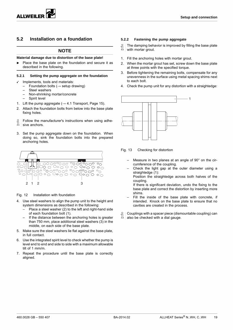
4. Check the pump unit for any distortion with a straightedge:
1
Fig. 13 Checking for distortion
– Measure in two planes at an angle of 90° on the cir-cumference of the coupling.
– Check the light gap at the outer diameter using astraightedge (1):Position the straightedge across both halves of thecoupling.If there is significant deviation, undo the fixing to thebase plate and correct the distortion by inserting moreshims.
– Fill the inside of the base plate with concrete, ifintended. Knock on the base plate to ensure that nocavities are created in the process.
Couplings with a spacer piece (dismountable coupling) canalso be checked with a dial gauge.
Only necessary if the pump unit is assembled on site.
NOTEMaterial damage caused by knocks and bumps!
Do not knock or hit any components of the pump.
NOTEMaterial damage caused by overheating!
Only use a fan-cooled motor with unobstructed air dis-charge in the direction of the pump.
5.5.1 Version with coupling (NTWH and CTWH series)
Only necessary if the pump unit is assembled on site.
NOTEMaterial damage caused by knocks and bumps!
Keep the coupling halves properly aligned when slippingthem on.
1. Smear a very thin coat of molybdenum disulfide (e.g.Molykote) on the shaft ends of the pump and motor.
2. Insert shaft keys.
3. Slip on the pump-side and motor-side coupling halves inline.– Without a mounting rig: remove the rubber buffers and
heat the coupling halves up to approximately 100 °C.
4. Tighten the grub screws on both coupling halves.
5. Raise the motor and position it on the bell housing/connec-tion piece.
6. Check the distance between the coupling halves with afeeler gauge:– Permissible gap (→ setup drawing)– Use the feeler gauge to measure the gap (A) between
the coupling halves.– Align the coupling halves if the gap is too wide.
7. Tighten the motor fixing screws.
5.5.2 Installation with stub shaft (NBWH, CBWH,NIWH and CIWH series)
Stub shaft, free from oil and grease
1
2
3
Fig. 15 Widening the stub shaft
1 Socket head cap screw
2 Stub shaft
3 Shaft key groove of motor shaft
WARNINGRisk of injury due to overturning motor!
Secure themotor to prevent overturning before workingon the stub shaft.
1. Remove retaining clamp:– To do so, unscrew the hexagon head bolts 901.10 from
the motor bell housing 341.01
2. Remove the guard sheet 686.01 from the motor bell hous-ing 341.01.
3. Remove the socket head cap screw 914.06 from the stubshaft 220.01.– For this, insert a Allen key into the cast-in recess in the
motor bracket.
Tighten the jack screw with a screwdriver without applyingany excessive force.
The motor must be mounted on the pump bracket beforethe pump unit is installed in the container.
4. Widen the stub shaft:– Screw the cheese head screw (M10 x 40 or M12 x 40
ISO 1207, not included in the scope of delivery) intothe stub shaft.
5. Install the flanged motor, while ensuring:– The slot of the stub shaft is opposite to the shaft key
groove of the motor shaft– No shaft key is fitted– The stub shaft is up against the collar of the motor shaft
6. Screw in the motor bolts and tighten them.
7. Undo and unscrew the jack screw. Screw in the sockethead cap screw 914.06 and tighten it with a torque wrench(→ 9.3.3 Tightening torques, Page 57).
8. Turn the pump by hand:– Ensure the pump can be turned without pressure
points.
9. Install the safety guarding.
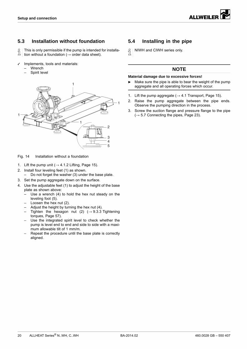
5.6 Planning the pipes
5.6.1 Specifying supports and flange connections
NOTEMaterial damage due to excessive forces and torquesexerted by the piping on the pump!
Do not exceed the permissible limits (→ 9.3.9 Flange loadsaccording to ISO 5199, Page 60).
1. Calculate the pipe forces, taking every possible operatingcondition into account:– Cold/warm– Empty/full– Unpressurized/pressurized– Shift in position of flanges
2. Ensure the pipe supports have permanent low-frictionproperties and do not seize up due to corrosion.
5.6.2 Specifying nominal diameters
Keep the flow resistance in the pipes as low as possible.
1. Where possible, make sure the nominal suction pipe diam-eter is ≥ as possible to the nominal suction flange diameter.– Recommended flow rate speed < 1 m/s
2. Make sure the nominal pressure pipe diameter is ≥ as pos-sible to the nominal pressure flange diameter.– Recommended flow rate speed < 3 m/s
5.6.3 Specifying pipe lengths
C
D
B
A
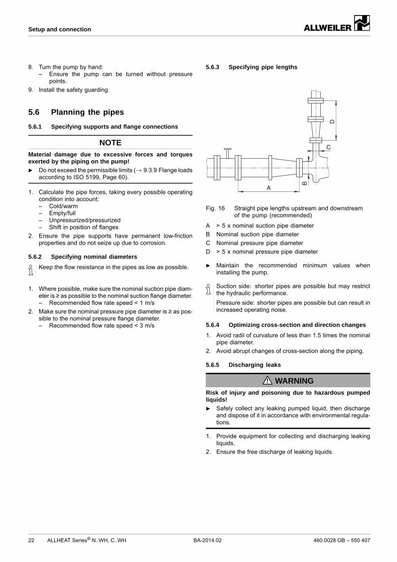
Fig. 16 Straight pipe lengths upstream and downstreamof the pump (recommended)
A > 5 x nominal suction pipe diameter
B Nominal suction pipe diameter
C Nominal pressure pipe diameter
D > 5 x nominal pressure pipe diameter
Maintain the recommended minimum values wheninstalling the pump.
Suction side: shorter pipes are possible but may restrictthe hydraulic performance.
Pressure side: shorter pipes are possible but can result inincreased operating noise.
5.6.4 Optimizing cross-section and direction changes
1. Avoid radii of curvature of less than 1.5 times the nominalpipe diameter.
2. Avoid abrupt changes of cross-section along the piping.
5.6.5 Discharging leaks
WARNINGRisk of injury and poisoning due to hazardous pumpedliquids!
Safely collect any leaking pumped liquid, then dischargeand dispose of it in accordance with environmental regula-tions.
1. Provide equipment for collecting and discharging leakingliquids.
5.6.6 Providing safety and control devices(recommended)
Avoid impurities
1. Integrate a filter in the suction pipe.
2. To monitor impurities, install a differential pressure gaugewith a contact manometer.
Avoid reverse running
Install a non-return valve between the pressure flange andthe gate valve to ensure the medium does not flow backwhen the pump is switched off.
Make provisions for isolating and shutting off the pipes
For maintenance and repair work.
Provide shut-off devices in the suction and pressure pipes.
Allow measurements of the operating conditions
1. Provide manometers for pressure measurements in thesuction and pressure pipes.
2. Provide load monitors (overload and underload) on themotor side.
3. Provide for pump-side temperature measurements.
5.7 Connecting the pipes
5.7.1 Keeping the piping clean
NOTEMaterial damage due to impurities in the pump!
Make sure no impurities can enter the pump.
1. Clean all piping parts and armatures prior to assembly.
2. Ensure no flange seals protrude inwards.
3. Remove any blind flanges, plugs, protective foils and/orprotective paint from flanges.
5.7.2 Installing auxiliary piping
Follow the manufacturers' specifications for any availableauxiliary systems.
1. Connect the auxiliary pipes to the auxiliary connections sothat they are stress-free and do not leak (→ setup drawing).
2. To avoid air pockets, run the pipes with a continuous slopeup to the pump.
5.7.3 Installing the suction pipe
1. Remove the transport and sealing covers from the pump.
2. To avoid air pockets, run the pipes with a continuous slopeup to the pump.
3. Ensure no seals protrude inwards.
4. For suction operation: install a foot valve in the suction pipeto prevent the pump and suction pipe from running emptyduring downtimes.
5.7.4 Installing the pressure pipe
1. Remove the transport and sealing covers from the pump.
2. Install the pressure pipe.
3. Ensure no seals protrude inwards.
5.7.5 Inspection for stress-free pipe connections
Piping installed and cooled down
NOTEMaterial damage due to distorted pump casing
Ensure that all pipes are stress relieved when connectedto the pump.
1. Disconnect the pipe connecting flanges from the pump.
2. Check whether the pipes can be moved freely in all direc-tions within the expected range of expansion:– Nominal diameter < 150 mm: by hand– Nominal diameter > 150 mm: with a small lever
3. Make sure the flange surfaces are parallel.
4. Reconnect the pipe connecting flanges to the pump.
5.7.6 Inspecting the support foot for distortion
1. Loosen the bolts connecting the support foot to the baseplate.
2. If the support foot moves, compensate for distortion:– Lateral shift: by means of slotted holes– Height shift: by means of metal shims
3. Screw the support foot back onto the base plate, makingsure that the bearing bracket is not distorted in the process.
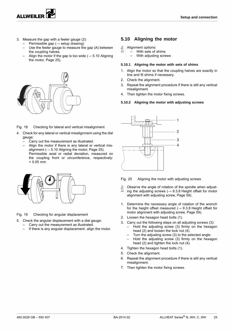
3. Measure the gap with a feeler gauge (2):– Permissible gap (→ setup drawing)– Use the feeler gauge to measure the gap (A) between
the coupling halves.– Align the motor if the gap is too wide (→ 5.10 Aligning
the motor, Page 25).
Fig. 18 Checking for lateral and vertical misalignment
4. Check for any lateral or vertical misalignment using the dialgauge:– Carry out the measurement as illustrated.– Align the motor if there is any lateral or vertical mis-
alignment (→ 5.10 Aligning the motor, Page 25).Permissible axial or radial deviation, measured onthe coupling front or circumference, respectively:< 0.05 mm
Fig. 19 Checking for angular displacement
5. Check the angular displacement with a dial gauge:– Carry out the measurement as illustrated.– If there is any angular displacement: align the motor.
5.10 Aligning the motor
Alignment options:– With sets of shims– With adjusting screws
5.10.1 Aligning the motor with sets of shims
1. Align the motor so that the coupling halves are exactly inline and fit shims if necessary.
2. Check the alignment.
3. Repeat the alignment procedure if there is still any verticalmisalignment.
4. Then tighten the motor fixing screws.
5.10.2 Aligning the motor with adjusting screws
1
43
2
Fig. 20 Aligning the motor with adjusting screws
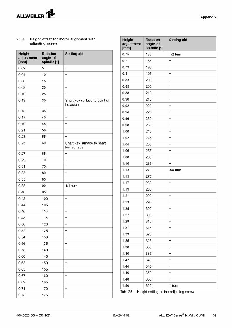
Observe the angle of rotation of the spindle when adjust-ing the adjusting screws (→ 9.3.8 Height offset for motoralignment with adjusting screw, Page 59).
1. Determine the necessary angle of rotation of the wrenchfor the height offset measured (→ 9.3.8 Height offset formotor alignment with adjusting screw, Page 59).
2. Loosen the hexagon head bolts (1).
3. Carry out the following steps on all adjusting screws (3):– Hold the adjusting screw (3) firmly on the hexagon
head (2) and loosen the lock nut (4).– Turn the adjusting screw (3) to the selected angle.– Hold the adjusting screw (3) firmly on the hexagon
head (2) and tighten the lock nut (4).
4. Tighten the hexagon head bolts (1).
5. Check the alignment.
6. Repeat the alignment procedure if there is still any verticalmisalignment.
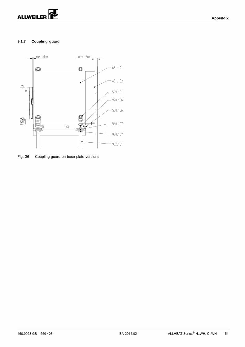
The nuts (920.106/107) are non-removable (secured bycrimping sleeves).
Base plate version
1. Installing the coupling guard (→ Figure Coupling guard onbase plate versions, Page 51).– Gap between coupling guard and pump < 8 mm– Gap between coupling guard and motor < 8 mm (set
the equalizing pipe (681.102) accordingly)
Flanged drive
2. If available ,install the coupling guard (two plates) on thebell housing.
For pumps in explosion hazard areas (→ ATEX additionalinstructions).
6.1 Putting the pump into servicefor the first time
6.1.1 Removing the preservative
Only necessary for pumps treated with preservative
(→ 4.4 Removing the preservative, Page 16).
6.1.2 Preparing auxiliary systems (if available)
The manufacturer does not accept any liability for damagearising from the installation or use of a third-party or unap-proved auxiliary system.
Sealing systems
1. Verify that the sealing medium is suitable to mix (i.e. com-patible) with the pumped medium.
2. Identify the sealing system (→ order data sheet)(→ 3.4.1 Sealing systems, Page 14).
3. Install the sealing system (→ manufacturer's specifica-tions).
4. Make sure the parameters required for the installed sealingsystem are met.
5. Ensure that the permissible container pressure is notexceeded on blocking pressure systems (→ manufac-turer's specifications).
6.1.3 Filling and bleeding
Auxiliary systems ready for operation
WARNINGRisk of injury and poisoning due to hazardous pumpedmedia!
Safely collect any leaking pumped medium and disposeof it in accordance with environmental rules and require-ments.
NOTEMaterial damage caused by dry running!
Make sure the pump is filled properly.
1. If necessary, fill the seal chamber with pumped liquid:– Bleed the pump using connection FF2/FV1.– If the pump is set up in a vertical position, also bleed
air using connection FF4/FV4.– Fill the pump with pumped liquid using connection
FF2/FV1.– If possible, turn the pump shaft by hand.
2. Fill the pump and the suction pipe with pumped medium.
3. Open the suction-side armature.
4. Open the pressure-side armature.
5. If present: open the auxiliary systems and check the flowrate.
Any available auxiliary systems are ready for operation
All safety equipment installed and tested for functionality
Pump prepared, filled and bled properly
Pumped liquids with a high viscosity can cause increasedpower consumption. We recommend using a minimumamount of pumping liquid until the operating temperaturehas been reached.
DANGERRisk of injury due to running pump!
Do not touch the running pump.
Ensure that the coupling guard is attached.
Do not carry out any work on the running pump.
Allow the pump to cool down completely before starting anywork.
DANGERRisk of injury and poisoning due to pumped liquid spray-ing out!
Use protective equipment when carrying out any work onthe pump.
NOTEMaterial damage caused by dry running!
Make sure the pump is filled properly.
NOTERisk of cavitation when throttling down the suction flowrate!
Fully open the suction-side armature and do not use it toadjust the flow rate.
Do not open the pressure-side fitting beyond the operatingpoint.
NOTEMaterial damage caused by overheating!
Do not operate the pump for long periods with the pressure-side fitting closed.
Observe the minimum flow rate (→ order data sheet).
1. Open the suction-side fitting.
2. Close the pressure-side fitting.
3. Switch on the motor and make sure it is running smoothly.
4. Once the motor has reached its nominal speed, openthe pressure-side fitting slowly until the operating point isreached.
5. For pumps with hot pumped liquids, make sure any tem-perature changes do not exceed 5 K/min.
6. Observe the following for use in high temperature systems:– Heat the pump to 100–130 °C– Bleed the pump using connection FF2/FV1 or FF4/FV4
7. After the first load under pressure and at operating temper-ature, check that the pump is not leaking.
8. If the pumped liquid is hot, switch off the pump briefly atoperating temperature, check the alignment of the couplingand realign the motor if necessary. (→ 5.9 Aligning thecoupling precisely, Page 24).
6.1.5 Switching off
Pressure-side fitting closed (recommended)
WARNINGRisk of injury due to hot pump parts!
Use protective equipment when carrying out any work onthe pump.
1. Switch off the motor.
2. Check all connecting bolts and tighten them if necessary.
3. On pump unit with flange bearing housing, align the supportfoot:– Unscrew all the screws of the support foot 183.01– Secure the support foot to the foundation– Make sure that the fastening screws 901.13 can be
inserted into slots of the motor bell housing– If necessary, adjust the support foot by placing metal
spacing shims underneath it– Put the washers 554.13 on the fastening screws
901.13– Secure the fastening screws 901.13 with hexagon nuts
Any available auxiliary systems are ready for operation
All safety equipment installed and tested for functionality
Pump prepared, filled and bled properly
DANGERRisk of injury due to running pump!
Do not touch the running pump.
Ensure that the coupling guard is attached.
Do not carry out any work on the running pump.
Allow the pump to cool down completely before starting anywork.
DANGERRisk of injury and poisoning due to pumped liquid spray-ing out!
Use protective equipment when carrying out any work onthe pump.
NOTEMaterial damage caused by dry running!
Make sure the pump is filled properly.
NOTERisk of cavitation when throttling down the suction flowrate!
Fully open the suction-side armature and do not use it toadjust the flow rate.
Do not open the pressure-side fitting beyond the operatingpoint.
NOTEMaterial damage caused by overheating!
Do not operate the pump for long periods with the pressure-side fitting closed.
Observe the minimum flow rate (→ order data sheet).
1. Open the suction-side fitting.
2. Close the pressure-side fitting.
3. Switch on the motor and make sure it is running smoothly.
4. Once the motor has reached its nominal speed, openthe pressure-side fitting slowly until the operating point isreached.
5. For pumps with hot pumped liquids, make sure any tem-perature changes do not exceed 5 K/min.
6. After the first load under pressure and at operating temper-ature, check that the pump is not leaking.
7. If the pumped liquid is hot, switch off the pump briefly atoperating temperature, check the alignment of the couplingand realign the motor if necessary (→ 5.9 Aligning the cou-pling precisely, Page 24).
6.2.2 Switching off
Pressure-side fitting closed (recommended)
WARNINGRisk of injury due to hot pump parts!
Use protective equipment when carrying out any work onthe pump.
Switch off the motor.
6.3 Shutting down
WARNINGRisk of injury and poisoning due to hazardous pumpedmedia!
Safely collect any leaking pumped medium and disposeof it in accordance with environmental rules and require-ments.
Take the following measures whenever the pump is shutdown:
Pump is Measure
...shut downfor a prolongedperiod
Take measures according tothe pumped liquid (→ Table8 Measures depending onthe behavior of the pumpedmedium, Page 30).
...emptied Close the suction-side andpressure-side armatures.
...dismounted Isolate the motor from its powersupply and secure it againstunauthorized switch-on.
...put intostorage
Follow the storage instructions(→ 4.3 Storage, Page 16).
Tab. 7 Measures to be taken if the pump is shut down
Duration of shutdown (dependingon process)
Behaviorof pumpedmedium
Short Long
Solids sediment Flush thepump.
Flush thepump.
Solidifying/freezing,non-corrosive
Heat up orempty thepump andcontainers.
Empty thepump andcontainers.
Solidifying/freezing,corrosive
Heat up orempty thepump andcontainers.
Empty thepump andcontainers.
Treat thepump andcontainerswith preser-vative.
Remains liquid,non-corrosive
– –
Remains liquid,corrosive
– Empty thepump andcontainers.
Treat thepump andcontainerswith preser-vative.
Tab. 8 Measures depending on the behaviorof the pumped medium
6.4 Start-up following a shutdown period
1. If the pump is shut down for over 1 year, take the followingmeasures before starting it up again:
Shutdown period Measure
> 1 year For versions with rollerbearings without lifetimelubrication: relubricate
> 2 years Replace elastomer seals(O-rings, shaft sealing rings).
Replace antifriction bearings.
Tab. 9 Measures to be taken after prolongedshutdown periods
2. Carry out all steps as for the initial start-up (→ 6.1 Puttingthe pump into service for the first time, Page 27).
6.5 Operating the stand-by pump
Stand-by pump filled and bled
Operate the stand-by pump at least once a week.
1. Completely open the suction-side armature.
2. Open the pressure-side fitting to the extent that thestand-by pump reaches its operating temperature and isheated through evenly (→ 6.2.1 Switching on, Page 29).
For pumps in explosion hazard areas (→ ATEX additionalinstructions).
Trained service technicians are available for fitting andrepair jobs. Present a pumped medium certificate (DINsafety data sheet or safety certificate) when requestingservice.
7.1 Inspections
The inspection intervals depend on the operational strainon the pump.
DANGERRisk of injury due to running pump!
Do not touch the running pump.
Do not carry out any work on the running pump.
WARNINGRisk of injury and poisoning due to hazardous pumpedmedia!
Use protective equipment when carrying out any work onthe pump.
For trouble-free operation, always ensure the following:– Maintenance of minimum flow rate– Temperature of antifriction bearings < 120 °C– No leaks– No cavitation– Suction-side gate valves open– Unclogged and clean filters– Sufficient pump ingress pressure– No unusual running noises or vibrations– No overloading of the system– Top up oil if necessary– Coupling alignment and condition of elastic parts– No excessive leakage at the shaft seal– Proper functioning of auxiliary systems– Adherence to the vibration limit value in accordance
with DIN ISO 10816-7, category 2
7.2 Maintenance
Service life of the antifriction bearings for operation withinthe permissible operating range: > 2 years
Intermittent operation, high temperatures, low viscositiesand aggressive ambient and process conditions reduce theservice life of antifriction bearings.
Mechanical seals are subject to natural wear, whichstrongly depends on the actual operating conditions.Therefore, general statements regarding their service lifecannot be made.
DANGERRisk of injury due to running pump!
Do not touch the running pump.
Do not carry out any work on the running pump.
Isolate the motor from its supply voltage and keep it lockedin that state when carrying out any fitting or maintenancework.
DANGERRisk of death due to electric shock!
Have all electrical work carried out by qualified electriciansonly.
WARNINGRisk of injury and poisoning due to hazardous or hotpumped media!
Use protective equipment when carrying out any work onthe pump.
Allow the pump to cool down completely before commenc-ing any work.
Make sure the pump is unpressurized.
Empty the pump, safely collect the pumped medium anddispose of it in accordance with environmental rules andrequirements.
7.2.1 Antifriction bearings lubricated with grease
1. As a precaution, replace antifriction bearings with lifetimelubrication every 2 years (recommended).The following antifriction bearings have been installed:
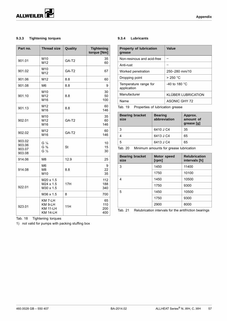
• Must be greased regularly(→ Table 21 Relubricationintervals for the antifrictionbearings, Page 57).
Tab. 10 Employed antifriction bearings
2. Make sure you use the correct type and minimum amountof grease when filling the bearing (→ 9.3.4 Lubricants,Page 57).
3. Fill the cavities between the rolling elements up to 40 %with grease.
4. Wipe off any excess grease with a soft object.
7.2.2 Mechanical seals
Mechanical seals have functional leaks (→ manufacturer'sspecifications).
Single mechanical seals with quenching: any drastic risein the level of the quenching system indicates a major leakat the product-side mechanical seal.
Double mechanical seals: any drastic pressure drop in theblocking system (loss of blocking fluid) indicates a majorleak at the product-side mechanical seal.
1. In the event of a larger leak: replace the mechanical sealand its auxiliary seals and check the integrity of the auxiliarysystems.
2. Recommended: Empty out the bearing bracket regularly inorder to replace old pumping liquid:– Take the pump out of operation (→ 6.3 Shutting down,
Page 29).– Open connection FD2 of bearing bracket and safely
collect the pumping liquid.– Fill and bleed the pump (→ 6.1.3 Filling and bleeding,
Page 27).
7.2.3 Carbon sleeve bearing
Carbon sleeve bearings are wear parts.
As a precautionary measure, replace carbon sleeve bear-ings every 2 years (recommended).
7.2.4 Sealing medium
Only on versions with quenching.
1. Check the filling level of the sealing medium.
2. After 4000 operating hours or when the maximum fillinglevel has been reached, replace the sealing medium:– Empty the sealing chamber and safely collect the seal-
ing medium.– Fill the seal chamber with sealing medium.
7.2.5 Cleaning the pump
NOTEHigh water pressure or spray water can damage bearings!
Do not clean bearing areas with a water or steam jet.
Isolate the motor from its supply voltage and keep it lockedin that state when carrying out any fitting or maintenancework.
DANGERRisk of death due to electric shock!
Have all electrical work carried out by qualified electriciansonly.
WARNINGRisk of injury and poisoning due to hazardous or hotpumped media!
Use protective equipment when carrying out any work onthe pump.
Allow the pump to cool down completely before commenc-ing any work.
Make sure the pump is unpressurized.
Empty the pump, safely collect the pumped medium anddispose of it in accordance with environmental rules andrequirements.
WARNINGRisk of injury due to heavy components!
Pay attention to the component weight. Lift and transportheavy components using suitable lifting gear.
Set down components safely and secure them againstoverturning or rolling away.
WARNINGRisk of injury during disassembly!
Secure the pressure-side gate valve against accidentalopening.
Depressurize the blocking pressure system, if available.
Wear protective gloves as components can become verysharp through wear or damage.
Remove spring-loaded components carefully (e.g.mechanical seal, tensioned bearing, valves etc.), as com-ponents can be ejected by the spring tension.
Observe the manufacturer's specifications (e.g. for themotor, coupling, mechanical seal, blocking pressure sys-tem, cardan shaft, drives, belt drive etc.).
7.3.1 Returning the pump to the manufacturer
Pump unpressurized
Pump completely empty
Electrical connections isolated and motor secured againstswitch-on
Pump cooled down
Coupling guard dismounted
With coupling with spacer piece: spacer piece removed
Auxiliary systems shut down, depressurized and emptied
Manometer lines, manometer and holdings dismounted
Enclose a truthfully and fully completed document of com-pliance when returning pumps or components to the man-ufacturer (→ 9.5 Safety certificate, Page 63).
Repair carried out Measure for return
...at the customer'spremises
Return the defectivecomponent to themanufacturer.
...at themanufacturer'spremises
Flush the pump anddecontaminate it if it wasused to pump hazardousmedia.
Return the complete pump(not disassembled) to themanufacturer.
Reinstall the components concentrically, without canting,in accordance with the markings made.
WARNINGRisk of injury due to heavy components!
Pay attention to the component weight. Lift and transportheavy components using suitable lifting gear.
Set down components safely and secure them againstoverturning or rolling away.
WARNINGRisk of injury during assembly!
Install spring-loaded components carefully (e.g. mechan-ical seal, tensioned bearing, valves etc.), as componentscan be ejected by the spring tension.
Observe the manufacturer's specifications (e.g. for themotor, coupling, mechanical seal, blocking pressure sys-tem, cardan shaft, drives, belt drive etc.).
NOTEMaterial damage due to unsuitable components!
Always replace lost or damaged screws with screws of thesame strength (→ 9.3.3 Tightening torques, Page 57).
Only replace seals with seals of the same material.
1. Observe the following during the installation:– Replace worn parts with genuine spare parts.– Replace seals, inserting them so that they cannot
rotate.– Maintain the specified tightening torques
(→ 9.3.3 Tightening torques, Page 57).
2. Clean all parts (→ 9.3.6 Cleaning agents, Page 58). Donot remove any prepared markings.
3. On version with a fan and stub shaft (NBWH, CBWH, NIWHand CIWH series):– Install the stub shaft (→ 5.5.2 Installation with stub
shaft (NBWH, CBWH, NIWH and CIWH series),Page 21).
– Push the fan 831.01with the tolerance ring 517.03 ontothe stub shaft 220.01 to the stop position.
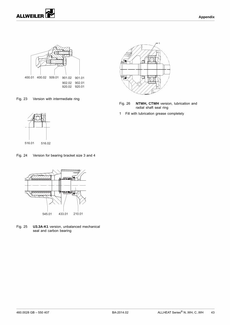
4. On NTWH and CTWH series:– Fill the space in front of and behind the shaft seal ring
421.01 with lubricant (→ Figure NTWH, CTWH ver-sion, lubrication and radial shaft seal ring, Page 43).
5. Replace the antifriction bearings.
6. Fill any open antifriction bearings without guard discs withgrease:– Make sure you use the correct type and mini-
mum amount of grease when filling the bearing(→ 9.3.4 Lubricants, Page 57).
– Fill the cavities between the rolling elements up to 40%with grease.
– Wipe off any excess grease with a soft object.
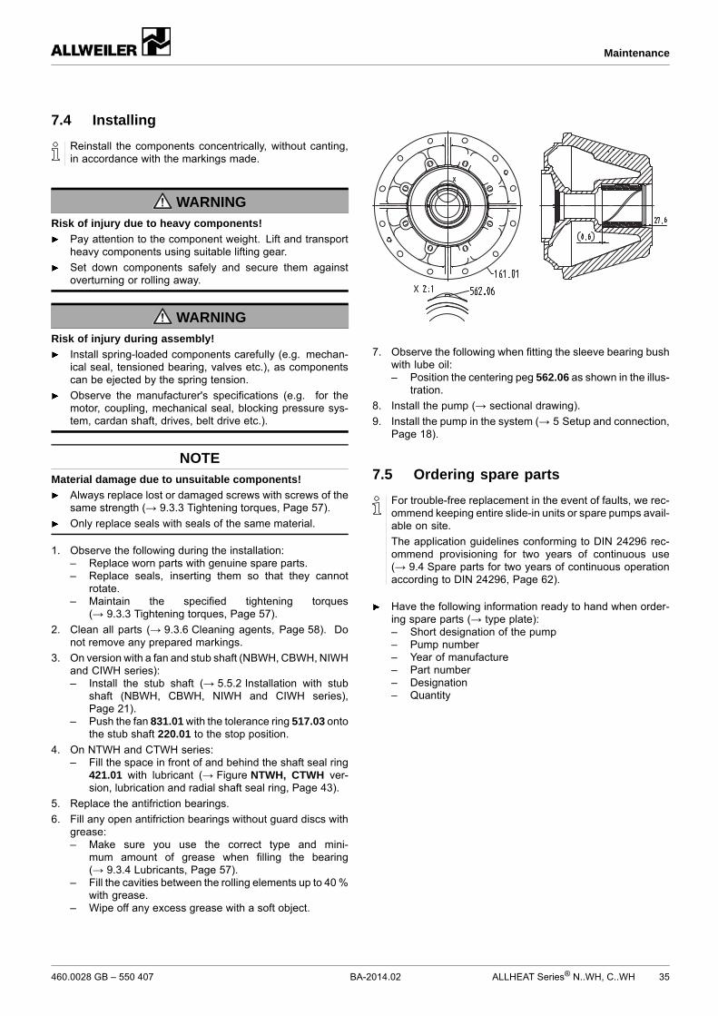
7. Observe the following when fitting the sleeve bearing bushwith lube oil:– Position the centering peg 562.06 as shown in the illus-
tration.
8. Install the pump (→ sectional drawing).
9. Install the pump in the system (→ 5 Setup and connection,Page 18).
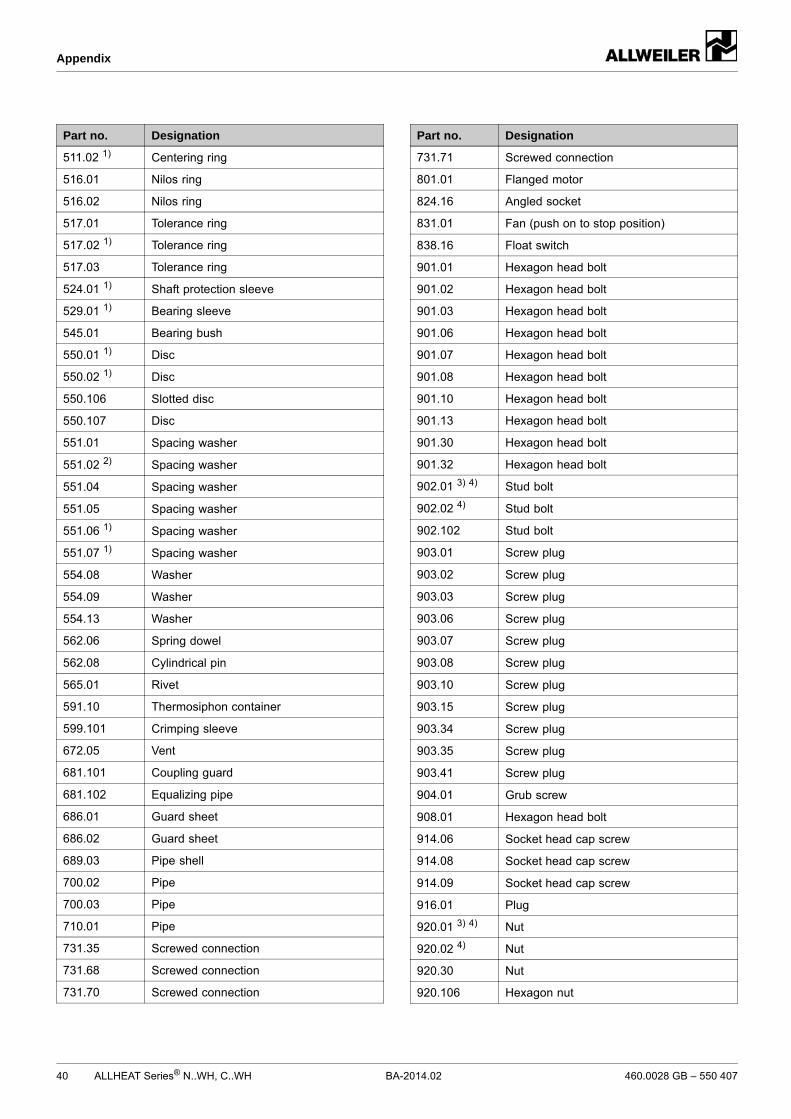
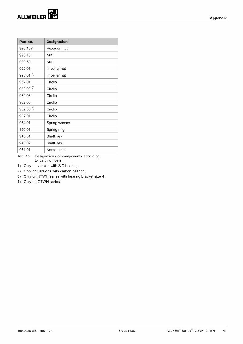
7.5 Ordering spare parts
For trouble-free replacement in the event of faults, we rec-ommend keeping entire slide-in units or spare pumps avail-able on site.
The application guidelines conforming to DIN 24296 rec-ommend provisioning for two years of continuous use(→ 9.4 Spare parts for two years of continuous operationaccording to DIN 24296, Page 62).
Have the following information ready to hand when order-ing spare parts (→ type plate):– Short designation of the pump– Pump number– Year of manufacture– Part number– Designation– Quantity
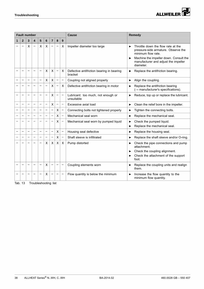
For faults which are not specified in the following table or can-not be traced back to the specified causes, please consult themanufacturer.
Possible faults are identified by a fault number in the tablebelow. This number identifies the respective cause and rem-edy in the troubleshooting list.
Fault Number
Pump not pumping 1
Pumping rate insufficient 2
Pumping rate excessive 3
Pumping pressure insufficient 4
Pumping pressure excessive 5
Pump running roughly 6
Antifriction bearing temperatures too high 7
Pump leaking 8
Motor power uptake excessive 9
Tab. 12 Fault number assignment
Fault number
1 2 3 4 5 6 7 8 9
Cause Remedy
X – – – – – – – – Supply/suction pipe and/or pressure pipeclosed by armature
Open the armature.
X – – – – – – – – Transport and sealing cover still in place Remove the transport and sealingcover.
Dismount the pump and inspect it fordry-running damage.
X – – – – X – – – Supply/suction pipe not bled properly ornot filled up completely
Fill up the pump and/or pipingcompletely and bleed them.
X – – – – X – – – Supply/suction pipe contains air pockets Install the armature for bleeding.
Correct the piping layout.
X X – X – X – – – Supply/suction pipe, pump or suctionstrainer blocked or encrusted
Clean the supply/suction pipe, pump orsuction strainer.
X X – X – X – – – Pump running in the wrong direction Swap any two phases on the motor.
X X – X – – – – – Motor speed too low Compare the required motor speed withthe specifications on the pump typeplate. Replace the motor if necessary.
Increase the motor speed if speedcontrol is available.
X X – X – X – – – Impeller out of balance or blocked Dismount the pump and inspect it fordry-running damage.
Clean the impeller.
X X – X – X – – – Air is sucked in Seal the source of malfunction.
X X – X – X – – – Excessive amount of gas: pump iscavitating
Consult the manufacturer.
X X – – X X – – – Pressure pipe blocked Clean the pressure pipe.
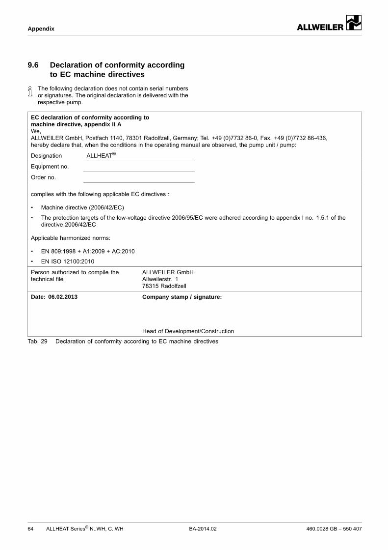
9.6 Declaration of conformity accordingto EC machine directives
The following declaration does not contain serial numbersor signatures. The original declaration is delivered with therespective pump.
EC declaration of conformity according tomachine directive, appendix II AWe,ALLWEILER GmbH, Postfach 1140, 78301 Radolfzell, Germany; Tel. +49 (0)7732 86-0, Fax. +49 (0)7732 86-436,hereby declare that, when the conditions in the operating manual are observed, the pump unit / pump:
Designation ALLHEAT®
Equipment no.
Order no.
complies with the following applicable EC directives :
• Machine directive (2006/42/EC)
• The protection targets of the low-voltage directive 2006/95/EC were adhered according to appendix I no. 1.5.1 of thedirective 2006/42/EC
Applicable harmonized norms:
• EN 809:1998 + A1:2009 + AC:2010
• EN ISO 12100:2010
Person authorized to compile thetechnical file
ALLWEILER GmbHAllweilerstr. 178315 Radolfzell
Date: 06.02.2013 Company stamp / signature:
Head of Development/Construction
Tab. 29 Declaration of conformity according to EC machine directives