VM 528 GB/2016.04 – Ident No. 795261 1 Volute Casing Centrifugal Pumps SERIES NB Block Design Application For pumping pure water, industrial water, sea water, con- densates, oils, brines, lyes and hot water. The fluids to be pumped must not contain any abrassive parti- cles nor chemically attack the pump materials. Main fields of application In cooling and heating systems, in circulating, water supply, water treatment, sea-water desalination, dedusting and spray painting plants as well as in air-conditioning, cooling, swimming pool and industrial engineering. Design and series construction Volute casing centrifugal pump, single entry, single or two- stage, of block design. Pump size according to DIN EN 733. Stub and motor shaft are rigidly coupled together. Shaft bear- ing in the motor by means of grease-lubricated groove ball bearings. The mating dimensions of the two-stage sizes 2/25–200, 2/32–200, 2/40–250, 2/50–250, except for dimen- sions f and l depending upon the driving motors, correspond to the single-stage designs. Volute casing with feet cast on. Horizontal or vertical installation, motor arrangement down- wards is not admissible. Performance data Delivery Q up to 480 m 3 /h Delivery head H up to 145 m Temperature of the fluid pumped t up to 140 °C Inlet pressure p s Pump outlet pressure as a function of the shaft diameter and the shaft seal with diameter 16, 24, 30 p d up to 16 bar with diameter 40 p d up to 10 bar Drive power P 0,25 up to 37 kW Nominal diameter, delivery flange DN d 25 up to 150 Branch position/flanges Suction branch: axial Delivery branch: radially upwards Flanges: up to DN 150 acc. to DIN EN 1092-2 PN 16 as from DN 200 acc. to DIN EN 1092-2 PN 10 / PN16 Contact protection The requirements of DIN EN 809 “Contact protection”, are met. Shaft seal By maintenance-free mechanical seal in unbalanced design (main dimensions acc. to DlN EN 12 756, design K, shape U). Combination of components The table on page 3 shows the combination possibilities of components of all NB sizes. The unit assembly system allows reduced stock keeping of spare parts. Explosion protection The pump fulfils the requirements according to EC Explosion Protection Directive 2014/34/EU (ATEX 100a) for equipment and equipment group II, category 2 G. Categorisation into temperature classes according to DIN EN 13463-1 depends on the temperature of the pumped me- dium. The max. permissible temperature of the pumped medi- um for the respective temperature classes are shown in the specific order data sheet. Note: In case of the operation of a category 2 pump, the un- acceptable heating of the pump surfaces caused by a possible operational fault must be prevented by a control mechanism. In case of an operation with constant parameters (pressure, temperature, speed = const.), a pump performance controller can be supplied with the pump to detect any operational faults. Drive Surface-cooled three-phase squirrel-cage induction motors, with locating-type bearing, IM V1 type of construction, en- closure IP55 according to IEC Standard, class F insulation, performances and main dimensions according to DIN EN 50 347, up to 2.2 kW 230/400V, from 3.0 kW 400/690 V. Attention: Motors provided by customers must also have a locating-type bearing! Dismantling the driving unit When dismantling the driving unit, the volute casing may re- main in the piping. Connections The following auxiliary connections are always provided: FD1 Draining FV1 Venting optional FF1 Filling PM1 Pressure measurement pump PM2 Pressure measurement pump inlet pressure plus maximum delivery head must not exceed the admissible pump outlet pressure allocation pump size / shaft diameter at the shaft seal, refer to pages 12 to 19 in case the temperature of fluids pumped exceeds 120°C, the admis- sible pump outlet pressure changes as follows: connection FF1 at sizes 20-160; 25-200 und 2/25-200 not existent; failure at connection PM2 possible flange-mounted PN10 flange-mounted PN16
Transcript
VM 528 GB/2016.04 – Ident No. 795261 1
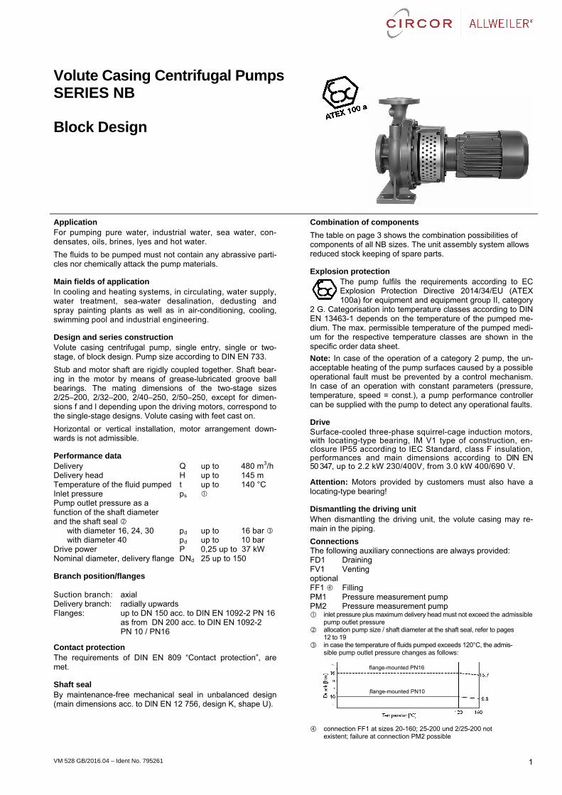
Volute Casing Centrifugal Pumps SERIES NB
Block Design
Application For pumping pure water, industrial water, sea water, con-densates, oils, brines, lyes and hot water.
The fluids to be pumped must not contain any abrassive parti-cles nor chemically attack the pump materials.
Main fields of application In cooling and heating systems, in circulating, water supply, water treatment, sea-water desalination, dedusting and spray painting plants as well as in air-conditioning, cooling, swimming pool and industrial engineering.
Design and series construction Volute casing centrifugal pump, single entry, single or two-stage, of block design. Pump size according to DIN EN 733.
Stub and motor shaft are rigidly coupled together. Shaft bear-ing in the motor by means of grease-lubricated groove ball bearings. The mating dimensions of the two-stage sizes 2/25–200, 2/32–200, 2/40–250, 2/50–250, except for dimen-sions f and l depending upon the driving motors, correspond to the single-stage designs. Volute casing with feet cast on.
Horizontal or vertical installation, motor arrangement down-wards is not admissible.
Performance data Delivery Q up to 480 m3/h Delivery head H up to 145 m Temperature of the fluid pumped t up to 140 °C Inlet pressure ps Pump outlet pressure as a function of the shaft diameter and the shaft seal
with diameter 16, 24, 30 pd up to 16 bar with diameter 40 pd up to 10 bar
Drive power P 0,25 up to 37 kW Nominal diameter, delivery flange DNd 25 up to 150
Branch position/flanges Suction branch: axial Delivery branch: radially upwards Flanges: up to DN 150 acc. to DIN EN 1092-2 PN 16
as from DN 200 acc. to DIN EN 1092-2 PN 10 / PN16
Contact protection The requirements of DIN EN 809 “Contact protection”, are met.
Shaft seal By maintenance-free mechanical seal in unbalanced design (main dimensions acc. to DlN EN 12 756, design K, shape U).
Combination of components
The table on page 3 shows the combination possibilities of components of all NB sizes. The unit assembly system allows reduced stock keeping of spare parts.
Explosion protection The pump fulfils the requirements according to EC Explosion Protection Directive 2014/34/EU (ATEX 100a) for equipment and equipment group II, category
2 G. Categorisation into temperature classes according to DIN EN 13463-1 depends on the temperature of the pumped me-dium. The max. permissible temperature of the pumped medi-um for the respective temperature classes are shown in the specific order data sheet.
Note: In case of the operation of a category 2 pump, the un-acceptable heating of the pump surfaces caused by a possible operational fault must be prevented by a control mechanism. In case of an operation with constant parameters (pressure, temperature, speed = const.), a pump performance controller can be supplied with the pump to detect any operational faults.
Drive Surface-cooled three-phase squirrel-cage induction motors, with locating-type bearing, IM V1 type of construction, en-closure IP55 according to IEC Standard, class F insulation, performances and main dimensions according to DIN EN 50 347, up to 2.2 kW 230/400V, from 3.0 kW 400/690 V.
Attention: Motors provided by customers must also have a locating-type bearing!
Dismantling the driving unit When dismantling the driving unit, the volute casing may re-main in the piping.
Connections The following auxiliary connections are always provided: FD1 Draining FV1 Venting optional FF1 Filling PM1 Pressure measurement pump PM2 Pressure measurement pump inlet pressure plus maximum delivery head must not exceed the admissible
pump outlet pressure allocation pump size / shaft diameter at the shaft seal, refer to pages
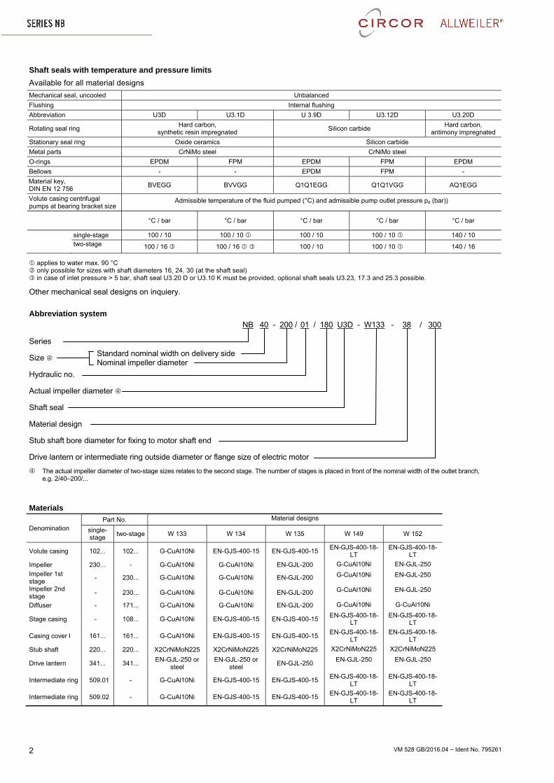
12 to 19 in case the temperature of fluids pumped exceeds 120°C, the admis-
sible pump outlet pressure changes as follows:
connection FF1 at sizes 20-160; 25-200 und 2/25-200 not existent; failure at connection PM2 possible
flange-mounted PN10
flange-mounted PN16
VM 528 GB/2016.04 – Ident No. 795261 2
Shaft seals with temperature and pressure limits
Available for all material designs
Mechanical seal, uncooled Unbalanced
Flushing Internal flushing
Abbreviation U3D U3.1D U 3.9D U3.12D U3.20D
Rotating seal ring Hard carbon,
synthetic resin impregnated Silicon carbide
Hard carbon, antimony impregnated
Stationary seal ring Oxide ceramics Silicon carbide
Metal parts CrNiMo steel CrNiMo steel
O-rings EPDM FPM EPDM FPM EPDM
Bellows - - EPDM FPM -
Material key, DIN EN 12 756
BVEGG BVVGG Q1Q1EGG Q1Q1VGG AQ1EGG
Volute casing centrifugal pumps at bearing bracket size
Admissible temperature of the fluid pumped (°C) and admissible pump outlet pressure pd (bar))
applies to water max. 90 °C only possible for sizes with shaft diameters 16, 24, 30 (at the shaft seal) in case of inlet pressure > 5 bar, shaft seal U3.20 D or U3.10 K must be provided, optional shaft seals U3.23, 17.3 and 25.3 possible.
Other mechanical seal designs on inquiery.
Abbreviation system NB 40 - 200 / 01 / 180 U3D - W133 - 38 / 300
Series
Size
Hydraulic no.
Actual impeller diameter
Shaft seal
Material design
Stub shaft bore diameter for fixing to motor shaft end
Drive lantern or intermediate ring outside diameter or flange size of electric motor
The actual impeller diameter of two-stage sizes relates to the second stage. The number of stages is placed in front of the nominal width of the outlet branch, e.g. 2/40–200/...
Intermediate ring 509.01 - G-CuAl10Ni EN-GJS-400-15 EN-GJS-400-15 EN-GJS-400-18-
LT EN-GJS-400-18-
LT
Intermediate ring 509.02 - G-CuAl10Ni EN-GJS-400-15 EN-GJS-400-15 EN-GJS-400-18-
LT EN-GJS-400-18-
LT
Standard nominal width on delivery sideNominal impeller diameter
VM 528 GB/2016.04 – Ident No. 795261 3
Combination of components
The following table shows the combination possibilities of components or spare parts of the NB sizes. Within a vertical column, parts with identical numbers are interchangeable.
Shaft diameter at
the shaft seal
Pump size
NB
Volutecasing
Impeller Impeller Diffuser Stage casing
Inter-mediate
ring
Casing cover
Stub shaft Drive lantern
Intermediate ring
1st stage
2nd stage
mm
The allocation to the sizes depends on speed, motor
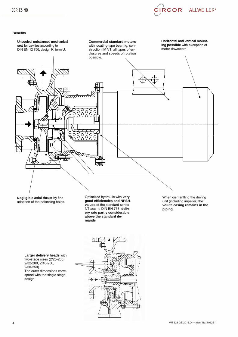
Optimized hydraulic with very good efficiencies and NPSH-values of the standard series NT acc. to DIN EN 733, deliv-ery rate partly considerable above the standard de-mands
When dismantling the driving unit (including impeller) the volute casing remains in the piping.
Negligible axial thrust by fine adaption of the balancing holes.
Uncooled, unbalanced mechanical seal for cavities according to DIN EN 12 756, design K, form U.
Commercial standard motors with locating-type bearing, con-struction IM V1, all types of en-closures and speeds of rotation possible.
Horizontal and vertical mount-ing possible with exception of motor downward.
Larger delivery heads with two-stage sizes (2/25-200, 2/32-200, 2/40-250, 2/50-250). The outer dimensions corre-spond with the single stage design.
VM 528 GB/2016.04 – Ident No. 795261 5
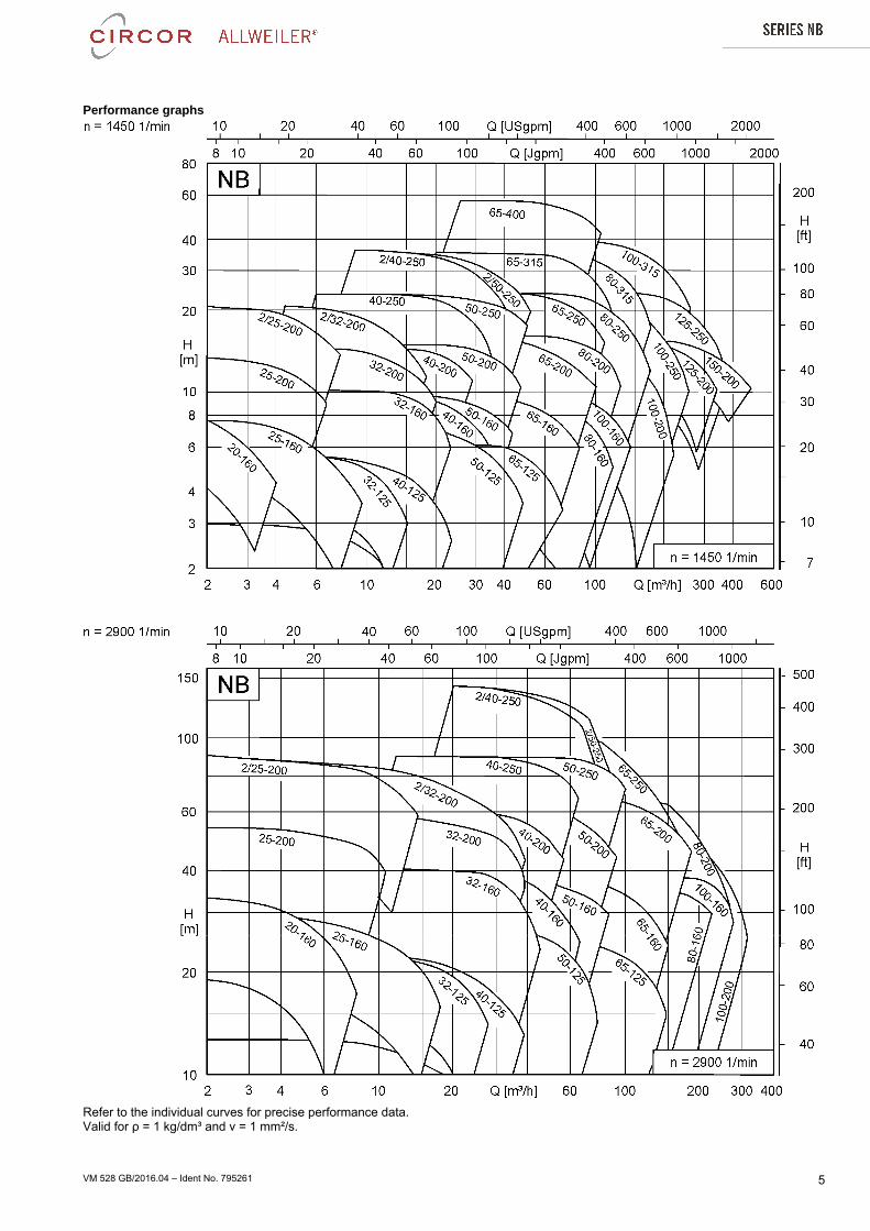
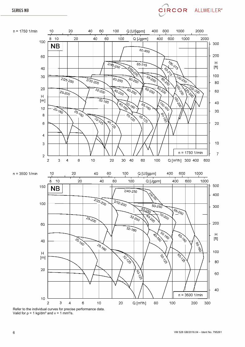
Performance graphs
Refer to the individual curves for precise performance data. Valid for ρ = 1 kg/dm³ and ν = 1 mm²/s.
VM 528 GB/2016.04 – Ident No. 795261 6
Refer to the individual curves for precise performance data. Valid for ρ = 1 kg/dm³ and ν = 1 mm²/s.
VM 528 GB/2016.04 – Ident No. 795261 7
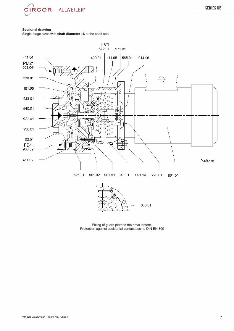
Sectional drawing Single-stage sizes with shaft diameter 16 at the shaft seal
Fixing of guard plate to the drive lantern. Protection against accidental contact acc. to DIN EN 809
VM 528 GB/2016.04 – Ident No. 795261 8
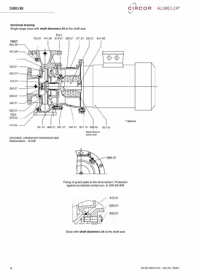
Sectional drawing Single-stage sizes with shaft diameters 24 at the shaft seal
Uncooled, unbalanced mechanical seal Abbreviation: U 3 D
Fixing of guard plate to the drive lantern. Protection against accidental contact acc. to DIN EN 809
Sizes with shaft diameters 24 at the shaft seal
depending on pump size
VM 528 GB/2016.04 – Ident No. 795261 9
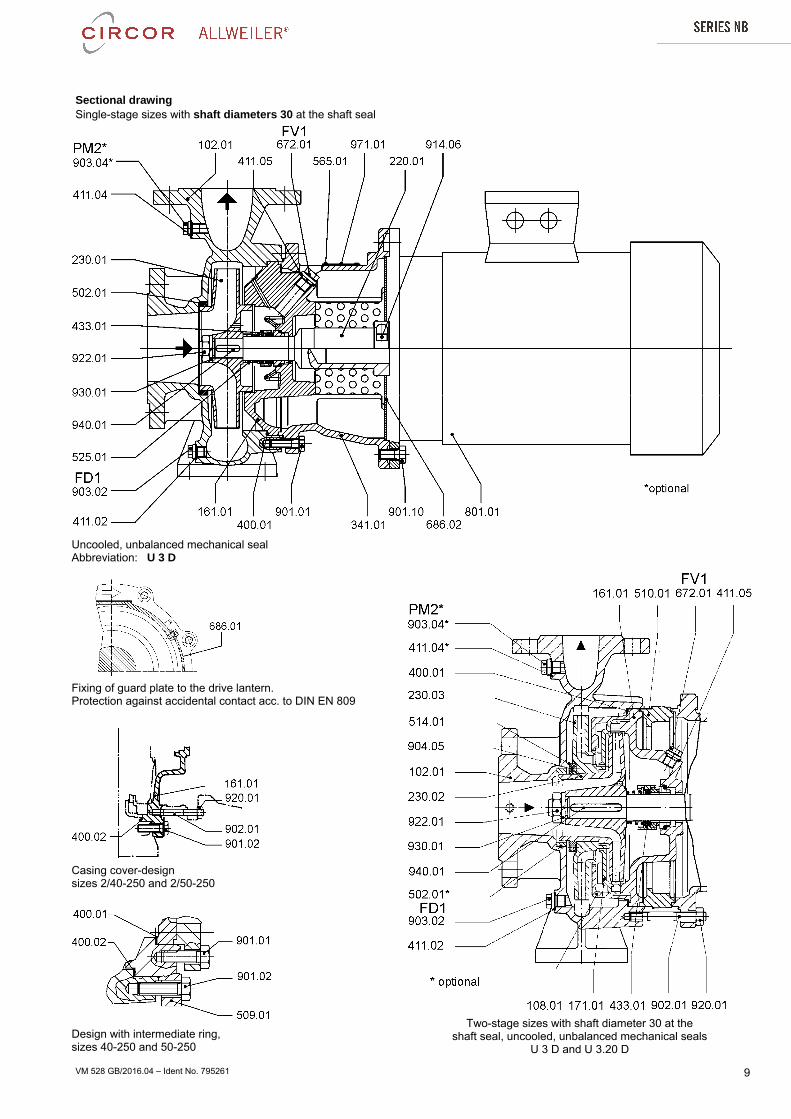
Sectional drawing Single-stage sizes with shaft diameters 30 at the shaft seal
Uncooled, unbalanced mechanical seal Abbreviation: U 3 D
Fixing of guard plate to the drive lantern. Protection against accidental contact acc. to DIN EN 809
Two-stage sizes with shaft diameter 30 at the
shaft seal, uncooled, unbalanced mechanical seals U 3 D and U 3.20 D
Casing cover-design sizes 2/40-250 and 2/50-250
Design with intermediate ring, sizes 40-250 and 50-250
VM 528 GB/2016.04 – Ident No. 795261 10
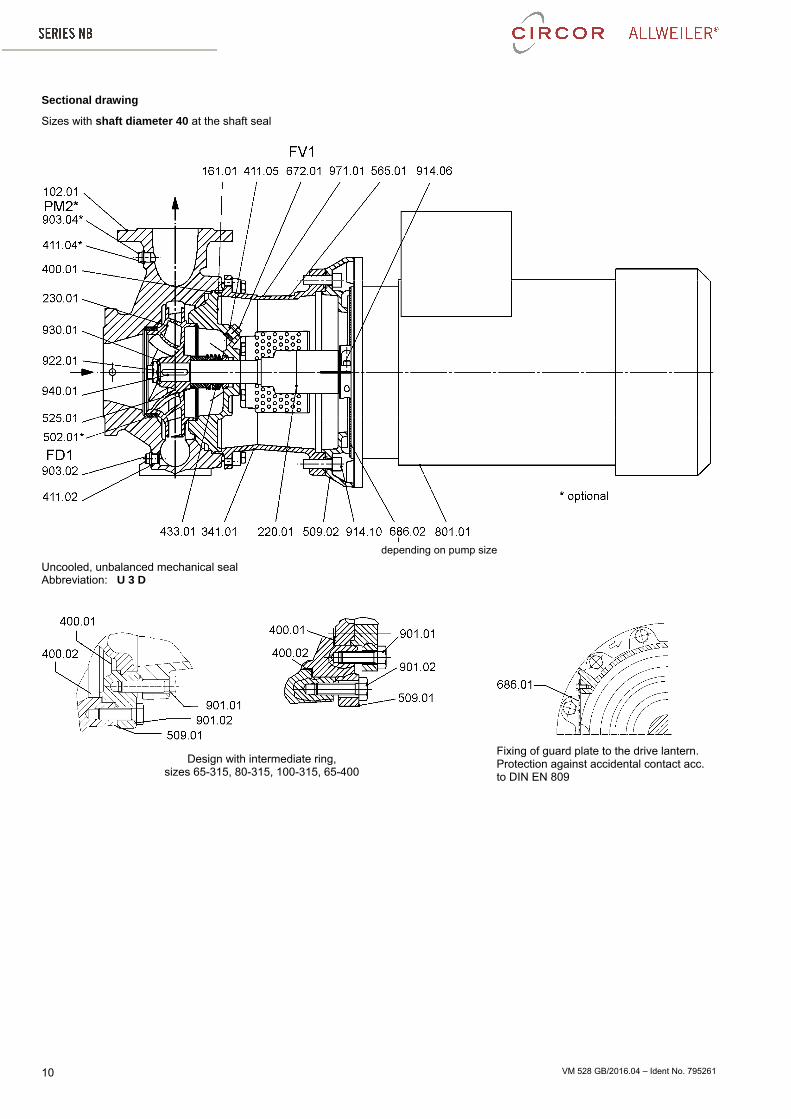
Sectional drawing
Sizes with shaft diameter 40 at the shaft seal
Uncooled, unbalanced mechanical seal Abbreviation: U 3 D
Design with intermediate ring, sizes 65-315, 80-315, 100-315, 65-400
Fixing of guard plate to the drive lantern. Protection against accidental contact acc. to DIN EN 809
depending on pump size
VM 528 GB/2016.04 – Ident No. 795261 11
List of components
Denomination Part-No Denomination Part-No
Volute casing 102.01 Hexagonal screw 901.02
Stage casing 108.01 Hexagonal screw 901.10
Casing cover 161.01 Stud bolt 902.01
Casing cover 161.05 Stud bolt 902.08
Diffuser 171.01 Screwed plug 903.01
Stub shaft 220.01 Screwed plug 903.02
Impeller 230.01 Screwed plug 903.03
Impeller 1st stage 230.02 Screwed plug 903.04
Impeller 2nd stage 230.03 Grub screw 904.05
Drive lantern 341.01 Socket head cap screw 914.06
Gasket 400.01 Socket head cap screw 914.10
Gasket 400.02 Hexagonal nut 920.01
Joint ring 411.01 Hexagonal nut 920.03
Joint ring 411.02 Impeller nut 922.01
Joint ring 411.04 Spring washer 930.01
Joint ring 411.05 Key 940.01
O-ring 412.01 Rating plate 971.01
Mechanical seal 433.01
Intermediate ring 502.01
Intermediate ring 509.01
Intermediate ring 509.02
Spacer ring 510.01
Threaded ring 514.01
Spacer sleeve 525.01
Rivet 565.01 Connections
Bleeder screw 672.01 FD1 Drainage
Guard plate 686.01 FF1 Filling
Guard plate 686.02 FV1 Venting
Flange-mounted motor 801.01 PM1 Pressure measurement
Hexagonal screw 901.01 PM2 Pressure measurement
VM 528 GB/2016.04 – Ident No. 795261 12
Aggregate dimensions: Sizes with shaft diameters 16, 24 and 30 at the shaft seal
Shaft diameter
at the shaft seal
Connections
Drain-ing
Fill- ing
Vent-ing
Pressure measurement
mm FD1 FF1 FV1 PM2 16
G 1/4 G 1/4 G 1/8
G 1/4 24 G 1/4 30 G 3/8
Connections at sizes 25-160, 25-200 and 2/25-200: FD1 = G 1/2; FF1 at sizes 20-160, 25-200 and 2/25-200 not existent.
Flanges acc. to DIN EN 1092-2 PN 16 (10)
DNd DNs
D bf k L No. of holes
25 115 16 85 14
4 32 140
18 100
19 40 150 110 50 165
20 125
65 185 145 80 200 22 160 8
Tolerances of connection dimensions Sense of rotation: clockwise as seen Dimensions in mm acc. to DIN EN 735 from the driving side without commitment
Shaft diameter at shaft seal
Pump size
Motor- size
Perfor-mance
Aggregate dimensions Allocation stub shaft/
motor bracket/ intermediate
ring Contained in abbreviation,
v. page 2
Pump dimensions Motor and flange dimen-sions approx. dimensions varying depending upon
manufacturer Exte
nsio
n di
m
Flanges Feet
mm kW DNs DNd a f a2 b1 b2 f1 h1 h2 b c m1 m2 n1 n2 s a1 x
16 20-160 71 0,25 0,37
25 25 63 118
- 108 108 -
112
145
50
14
100 70
220 180 M10 160
62 14/160
80 0,55 0,75 138 200 19/200
24
32-125 71 0,25 0,37
50 32
80
148 -
96
96
-
140
15
190 140
M12
160
89
14/160 80 0,55 0,75
200 19/200
90 S 1,1 24/200
40-125 71 0,25 0,37
65
40 110 210 160 160 14/160
80 0,55 0,75 200
19/200 90 S 1,1 24/200
50-125
71 0,25 0,37
50
100
110 130 132 160 240 190
160 14/160 80 0,55 0,75
200 19/200
90 S 1,1 24/200
90 L 1,5 100 L 2,2 3 250 28/250
65-125
71 0,25 0,37
80 65 120 148 160 180 65 125 95 280 212
160
95
14/160 80 0,55 0,75
200 19/200
90 S 1,1 24/200
90 L 1,5 100 L 2,2 3 250 28/250
30
25-160 80 0,55 0,75
40 25 80
149
-
133 133
-
132 160
50 100 70 240 190 200
102
19/200
25-200 80 0,55 0,75
132 132 160 180
90 S 1,1 24/200
90 L 1,5
2/25-200
80 0,55 0,75
183
19/200
90 S 1,1 24/200
90 L 1,5
100 L 2,2 3 193 250 28/250
s for screws
Arrangement 4 holes
Arrangement 8 holes
n = 1450/1750 min-1
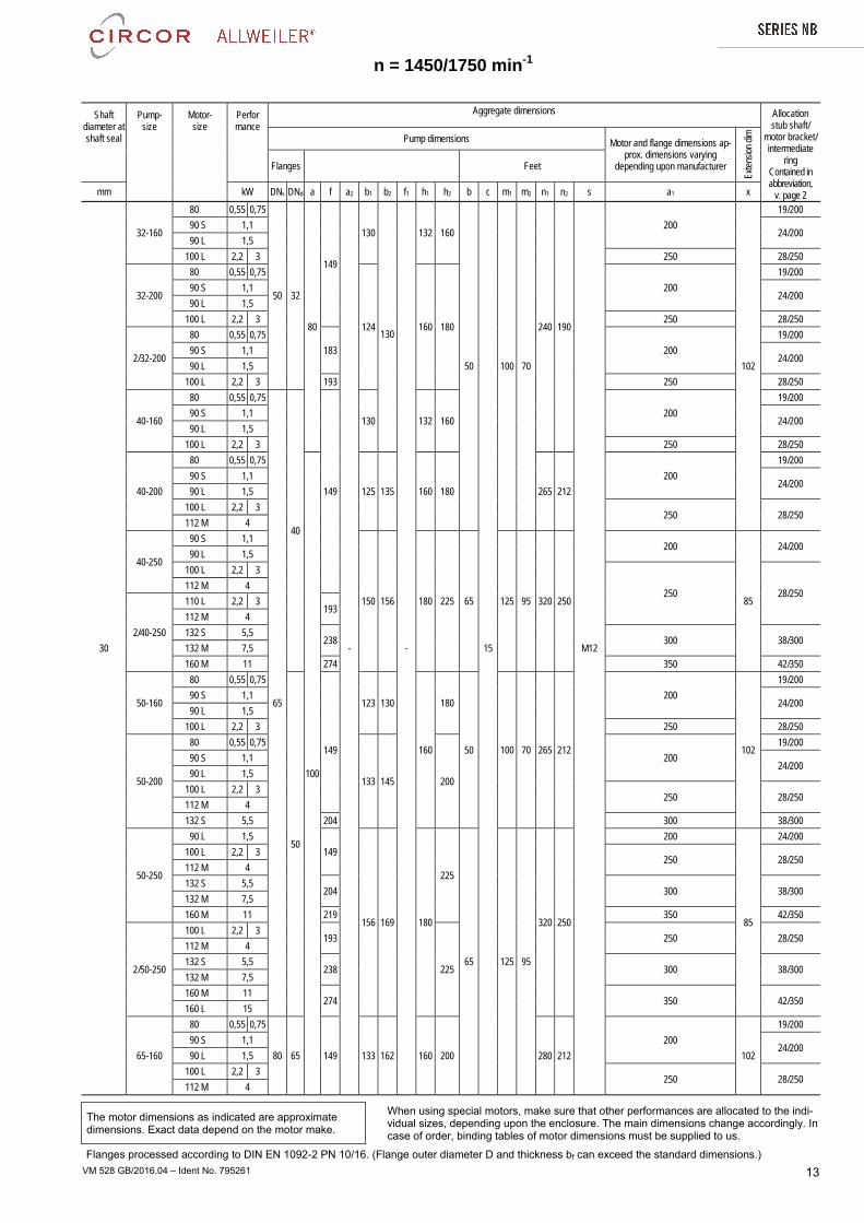
VM 528 GB/2016.04 – Ident No. 795261 13
Shaft diameter at shaft seal
Pump- size
Motor- size
Perfor mance
Aggregate dimensions Allocation stub shaft/
motor bracket/ intermediate
ring Contained in abbreviation,
v. page 2
Pump dimensions Motor and flange dimensions ap-prox. dimensions varying
depending upon manufacturer
Exte
nsio
n di
m
Flanges Feet
mm kW DNs DNd a f a2 b1 b2 f1 h1 h2 b c m1 m2 n1 n2 s a1 x
30
32-160
80 0,55 0,75
50 32
80
149
-
130
130
-
132 160
50
15
100 70
240 190
M12
200
102
19/200
90 S 1,1 24/200
90 L 1,5
100 L 2,2 3 250 28/250
32-200
80 0,55 0,75
124 160 180
200
19/200
90 S 1,1 24/200
90 L 1,5
100 L 2,2 3 250 28/250
2/32-200
80 0,55 0,75
183 200
19/200
90 S 1,1 24/200
90 L 1,5
100 L 2,2 3 193 250 28/250
40-160
80 0,55 0,75
65
40
149
130 132 160 200
19/200
90 S 1,1 24/200
90 L 1,5
100 L 2,2 3 250 28/250
40-200
80 0,55 0,75
100
125 135 160 180 265 212
200
19/200
90 S 1,1 24/200
90 L 1,5
100 L 2,2 3 250 28/250
112 M 4
40-250
90 S 1,1
150 156 180 225 65 125 95 320 250
200
85
24/200 90 L 1,5
100 L 2,2 3
250 28/250 112 M 4
2/40-250
110 L 2,2 3 193
112 M 4
132 S 5,5 238 300 38/300
132 M 7,5
160 M 11 274 350 42/350
50-160
80 0,55 0,75
50
149
123 130
160
180
50 100 70 265 212
200
102
19/200
90 S 1,1 24/200
90 L 1,5
100 L 2,2 3 250 28/250
50-200
80 0,55 0,75
133 145 200
200
19/200
90 S 1,1 24/200
90 L 1,5
100 L 2,2 3 250 28/250
112 M 4
132 S 5,5 204 300 38/300
50-250
90 L 1,5
149
156 169 180
225
65 125 95
320 250
200
85
24/200
100 L 2,2 3 250 28/250
112 M 4
132 S 5,5 204 300 38/300
132 M 7,5
160 M 11 219 350 42/350
2/50-250
100 L 2,2 3 193
225
250 28/250 112 M 4
132 S 5,5 238 300 38/300
132 M 7,5
160 M 11 274 350 42/350
160 L 15
65-160
80 0,55 0,75
80 65 149 133 162 160 200 280 212
200
102
19/200
90 S 1,1 24/200
90 L 1,5
100 L 2,2 3 250 28/250
112 M 4
The motor dimensions as indicated are approximate dimensions. Exact data depend on the motor make.
When using special motors, make sure that other performances are allocated to the indi-vidual sizes, depending upon the enclosure. The main dimensions change accordingly. In case of order, binding tables of motor dimensions must be supplied to us.
Flanges processed according to DIN EN 1092-2 PN 10/16. (Flange outer diameter D and thickness bf can exceed the standard dimensions.)
n = 1450/1750 min-1
VM 528 GB/2016.04 – Ident No. 795261 14
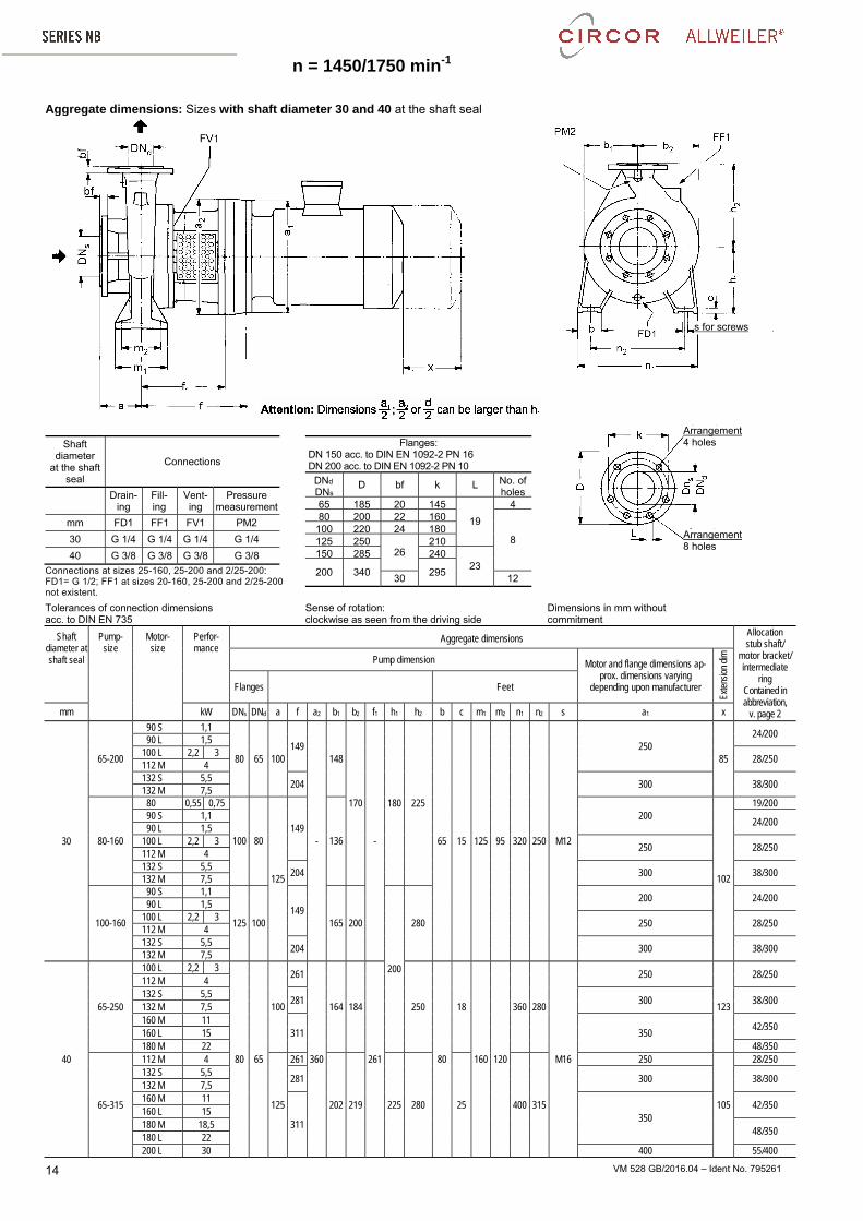
Aggregate dimensions: Sizes with shaft diameter 30 and 40 at the shaft seal
Shaft diameter
at the shaft seal
Connections
Drain-ing
Fill- ing
Vent-ing
Pressure measurement
mm FD1 FF1 FV1 PM2
30 G 1/4 G 1/4 G 1/4 G 1/4
40 G 3/8 G 3/8 G 3/8 G 3/8
Connections at sizes 25-160, 25-200 and 2/25-200: FD1= G 1/2; FF1 at sizes 20-160, 25-200 and 2/25-200 not existent.
Flanges: DN 150 acc. to DIN EN 1092-2 PN 16 DN 200 acc. to DIN EN 1092-2 PN 10
DNd DNs
D bf k L No. of holes
65 185 20 145
19
480 200 22 160
8 100 220 24 180125 250
26 210
150 285 24023
200 340 295 30 12
Tolerances of connection dimensions acc. to DIN EN 735
Sense of rotation: clockwise as seen from the driving side
Dimensions in mm without commitment
Shaft diameter at shaft seal
Pump- size
Motor- size
Perfor- mance
Aggregate dimensions Allocation stub shaft/
motor bracket/ intermediate
ring Contained in abbreviation,
v. page 2
Pump dimension Motor and flange dimensions ap-prox. dimensions varying
depending upon manufacturer
Exte
nsio
n di
m
Flanges Feet
mm kW DNs DNd a f a2 b1 b2 f1 h1 h2 b c m1 m2 n1 n2 s a1 x
30
65-200
90 S 1,1
80 65 100 149
-
148
170
-
180 225
65 15 125 95 320 250 M12
250 85
24/200 90 L 1,5
100 L 2,2 3 28/250
112 M 4 132 S 5,5
204 300 38/300 132 M 7,5
80-160
80 0,55 0,75
100 80
125
149 136
200
102
19/200 90 S 1,1
24/200 90 L 1,5
100 L 2,2 3 250 28/250
112 M 4 132 S 5,5
204 300 38/300 132 M 7,5
100-160
90 S 1,1
125 100 149
165 200
200
280
200 24/200 90 L 1,5
100 L 2,2 3 250 28/250
112 M 4 132 S 5,5
204 300 38/300 132 M 7,5
40
65-250
100 L 2,2 3
80 65
100
261
360
164 184
261
250
80
18
160 120
360 280
M16
250
123
28/250 112 M 4 132 S 5,5
281 300 38/300 132 M 7,5 160 M 11
311 350 42/350
160 L 15 180 M 22 48/350
65-315
112 M 4
125
261
202 219 225 280 25 400 315
250
105
28/250 132 S 5,5
281 300 38/300 132 M 7,5 160 M 11
311 350
42/350 160 L 15 180 M 18,5
48/350 180 L 22 200 L 30 400 55/400
s for screws
Arrangement 4 holes
Arrangement 8 holes
n = 1450/1750 min-1
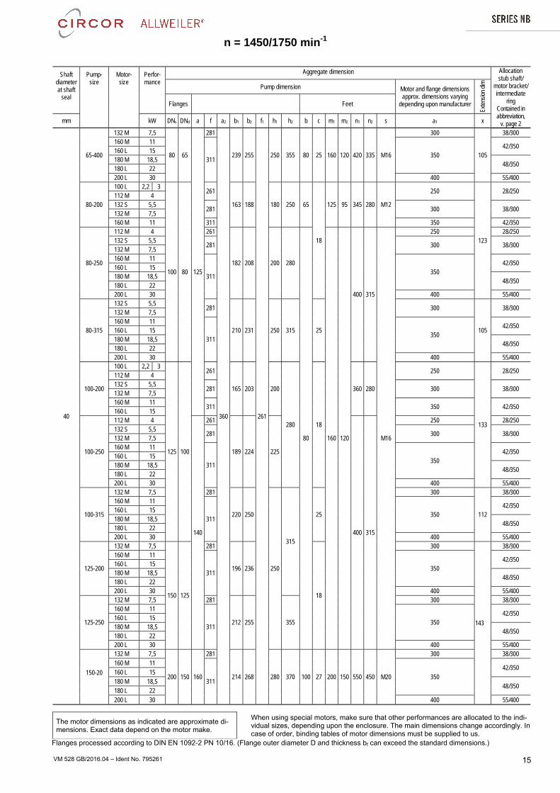
VM 528 GB/2016.04 – Ident No. 795261 15
Shaft diameter at shaft
seal
Pump- size
Motor- size
Perfor- mance
Aggregate dimension Allocation stub shaft/
motor bracket/ intermediate
ring Contained in abbreviation,
v. page 2
Pump dimension Motor and flange dimensions approx. dimensions varying
depending upon manufacturer
Exte
nsio
n di
m
Flanges Feet
mm kW DNs DNd a f a2 b1 b2 f1 h1 h2 b c m1 m2 n1 n2 s a1 x
40
65-400
132 M 7,5
80 65
125
281
360
239 255
261
250 355 80 25 160 120 420 335 M16
300
105
38/300 160 M 11
311 350
42/350 160 L 15 180 M 18,5
48/350 180 L 22 200 L 30 400 55/400
80-200
100 L 2,2 3
100 80
261
163 188 180 250 65
18
125 95 345 280 M12
250
123
28/250 112 M 4 132 S 5,5
281 300 38/300 132 M 7,5 160 M 11 311 350 42/350
80-250
112 M 4 261
182 208 200 280
80 160 120
400 315
M16
250 28/250 132 S 5,5
281 300 38/300 132 M 7,5 160 M 11
311 350
42/350 160 L 15 180 M 18,5
48/350 180 L 22 200 L 30 400 55/400
80-315
132 S 5,5 281
210 231 250 315 25
300
105
38/300 132 M 7,5 160 M 11
311 350
42/350 160 L 15 180 M 18,5
48/350 180 L 22 200 L 30 400 55/400
100-200
100 L 2,2 3
125 100
261
165 203 200
280 18
360 280
250
133
28/250 112 M 4 132 S 5,5
281 300 38/300 132 M 7,5 160 M 11
311 350 42/350 160 L 15
100-250
112 M 4
140
261
189 224 225
400 315
250 28/250 132 S 5,5
281 300 38/300 132 M 7,5 160 M 11
311 350
42/350 160 L 15 180 M 18,5
48/350 180 L 22 200 L 30 400 55/400
100-315
132 M 7,5 281
220 250
250
315
25
300
112
38/300 160 M 11
311 350
42/350 160 L 15 180 M 18,5
48/350 180 L 22 200 L 30 400 55/400
125-200
132 M 7,5
150 125
281
196 236
18
300
143
38/300 160 M 11
311 350
42/350 160 L 15 180 M 18,5
48/350 180 L 22 200 L 30 400 55/400
125-250
132 M 7,5 281
212 255 355
300 38/300 160 M 11
311 350
42/350 160 L 15 180 M 18,5
48/350 180 L 22 200 L 30 400 55/400
150-20
132 M 7,5
200 150 160
281
214 268 280 370 100 27 200 150 550 450 M20
300 38/300 160 M 11
311 350
42/350 160 L 15 180 M 18,5
48/350 180 L 22 200 L 30 400 55/400
The motor dimensions as indicated are approximate di-mensions. Exact data depend on the motor make.
When using special motors, make sure that other performances are allocated to the indi-vidual sizes, depending upon the enclosure. The main dimensions change accordingly. In case of order, binding tables of motor dimensions must be supplied to us.
n = 1450/1750 min-1
Flanges processed according to DIN EN 1092-2 PN 10/16. (Flange outer diameter D and thickness bf can exceed the standard dimensions.)
VM 528 GB/2016.04 – Ident No. 795261 16
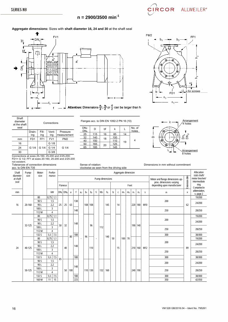
Aggregate dimensions: Sizes with shaft diameter 16, 24 and 30 at the shaft seal
Shaft diameter
at the shaft seal
Connections
Drain-ing
Fill- ing
Vent-ing
Pressure measurement
mm FD1 FF1 FV1 PM2
16
G 1/4 G 1/4
G 1/8
G 1/4 24 G 1/4
30 G 3/8
Connections at sizes 25-160, 25-200 and 2/25-200: FD1= G 1/2; FF1 at sizes 20-160, 25-200 and 2/25-200 not existent.
Flanges acc. to DIN EN 1092-2 PN 16 (10)
DNd DNs
D bf k L No. of holes
25 115 16 85 14
4 32 140 18 100
19 40 150 11050 165 20 12565 185 145
Tolerances of connection dimensions acc. to DIN EN 735
Sense of rotation: clockwise as seen from the driving side
Dimensions in mm without commitment
Shaft diameter at shaft
seal
Pump- size
Motor- size
Perfor- mance
Aggregate dimension Allocation stub shaft/
motor bracket/ intermediate
ring Contained in abbreviation,
v. page 2
Pump dimensions Motor and flange dimensions ap-prox. dimensions varying
depending upon manufacturer Ex
tens
ion
dim
Flanese Feet
mm kW DNs DNd a f a2 b1 b2 f1 h01 h2 b c m1 m2 n1 n2 s a1 x
16 20-160
80 0,75 1,1
25 25 63 138
-
108 108
-
112
145
50
14
100 70
220 180 M10 200
62
19/200 90 S 1,5
24/200 90 L 2,2
100 L 3 148 250 28/250
112 M 4
24
32-125
80 0,75 1,1
50 32
80
148
96
96
140
15
190 140
M12
200
89
19/200 90 S 1,5
24/200 90 L 2,2
100 L 3 250 28/250
112 M 4 132 S 5,5 7,5 188 300 38/300
40-125
80 0,75 1,1
65
40 148
110 210 160
200 19/200
90 S 1,5 24/200
90 L 2,2 100 L 3
250 28/250 112 M 4 132 S 5,5 7,5 188 300 38/300
50-125
90 S 1,5
50 100 148
110 130 132 160 240 190
200 24/200 90 L 2,2
100 L 3 250 28/250
112 M 4 132 S 5,5 7,5 188 300 38/300 160 M 11 15 223 350 42/350
s for screws
Arrangement 4 holes
Arrangement 8 holes
n = 2900/3500 min-1n = 2900/3500 min-1
VM 528 GB/2016.04 – Ident No. 795261 17
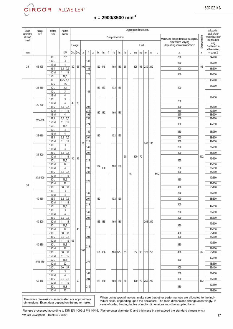
Shaft diameter at shaft
seal
Pump- size
Motor- size
Perfor- mance
Aggregate dimensions Allocation stub shaft/
motor bracket/ intermediate
ring Contained in abbreviation,
v. page 2
Pump dimensions Motor and flange dimensions approx.
dimensions varying depending upon manufacturer
Exte
nsio
n di
m
Flanges Feet
mm kW DNs DNd a f a2 b1 b2 f1 h1 h2 b c m1 m2 n1 n2 s a1 x
24 65-125
90 L 2,2
80 65 100
148
-
120 148
-
160 180 65
15
125 95 280 212
M12
200
95
24/200 100 L 3
250 28/250 112 M 4 132 S 5,5 7,5 188 300 38/300 160 M 11 15
223 350 42/350 160 L 18,5
30
25-160
80 0,75 1,1
40 25
80
149 133 133 132 160
50 100 70
240 190
200
102
19/200 90 S 1,5
24/200 90 L 2,2
100 L 3
28/250 112 M 4
25-200
100 L 3
132 132 160 180
250 112 M 4 132 S 5,5 7,5 204 300 38/300 160 M 11 15 219 350 42/350
2/25-200
112 M 4 193 250 28/250 132 S 5,5 7,5 238 300 38/300 160 M 11 15
274 350 42/350 160 L 18,5
32-160
100 L 3
50 32
149 130
130
132 160 250 28/250
112 M 4 132 S 5,5 7,5 204 300 38/300 160 M 11 15 219 350 42/350
32-200
100 L 3 149
124 160 180
250 28/250 112 M 4 132 S 5,5 7,5 204 300 38/300 160 M 11 15
219 350 42/350
160 L 18,5 180 M 22 48/350
2/32-200
112 M 4 193 250 28/250 132 S 5,5 7,5 238 300 38/300 160 M 11 15
274 350
42/350 160 L 18,5 180 M 22 48/350 200 L 30 37 400 55/400
40-160
100 L 3
65
40
149
130 132 160
250 28/250 112 M 4 132 S 5,5 7,5 204 300 38/300 160 M 11 15
219 350
42/350 160 L 18,5
40-200
100 L 3
100
149
125 135 160 180 265 212
250 28/250 112 M 4 132 S 5,5 7,5 204 300 38/300 160 M 11 15
219 350
42/350 160 L 18,5 180 M 22 48/350 200 L 30 37 400 55/400
40-250
132 S 5,5 7,5 204
150 156 180 225 65 25 95 320 250
300
85
38/300 160 M 11 15
219 350
42/350 160 L 18,5 180 M 22 48/350 200 L 30 37 400 55/400
2/40-250
160 M 11 15
274 350
42/350 160 L 18,5 180 M 22 48/350 200 L 30 37 400 55/400
50-160
100 L 3
50
149
123 130 160 180 50 100 70 265 212
250
102
28/250 112 M 4 132 S 5,5 7,5 204 300 38/300 160 M 11 15
219 350 42/350
160 L 18,5 180 M 22 48/350
The motor dimensions as indicated are approximate dimensions. Exact data depend on the motor make.
When using special motors, make sure that other performances are allocated to the indi-vidual sizes, depending upon the enclosure. The main dimensions change accordingly. In case of order, binding tables of motor dimensions must be supplied to us.
Flanges processed according to DIN EN 1092-2 PN 10/16. (Flange outer diameter D and thickness bf can exceed the standard dimensions.)
n = 2900/3500 min-1
VM 528 GB/2016.04 – Ident No. 795261 18
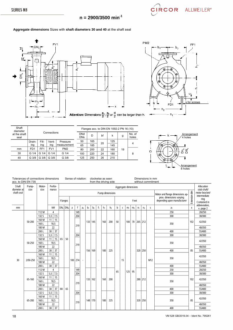
Aggregate dimensions Sizes with shaft diameters 30 and 40 at the shaft seal
Shaft diameter
at the shaft seal
Connections
Drain-ing
Fill- ing
Vent-ing
Pressure measurement
mm FD1 FF1 FV1 PM2
30 G 1/4 G 1/4 G 1/4 G 1/4
40 G 3/8 G 3/8 G 3/8 G 3/8
Flanges acc. to DIN EN 1092-2 PN 16 (10)
DNd DNs
D bf k g No. of holes
50 165 20
125
19
4 65 185 145
80 200 22 160
8 100 220 24 180
125 250 26 210
Tolerances of connections dimensions Sense of rotation: clockwise as seen Dimensions in mm acc. to DIN EN 735 from the driving side without commitment
Shaft diameter at shaft seal
Pump- size
Motor- size
Perfor- mance
Aggregate dimensions Allocation stub shaft/
motor bracket/ intermediate
ring Contained in abbreviation,
v. page 2
Pump dimensions Motor and flange dimensions ap-prox. dimensions varying
depending upon manufacturer
Exte
nsio
n di
m
Flanges Feet
mm kW DNs DNd a f a2 b1 b2 f1 h1 h2 b c m1 m2 n1 n2 s a1 x
30
50-200
112 M 4
65 50
100
149
-
133 145
-
160 200 50
15
100 70 265 212
M12
250
102
28/250 132 S 5,5 7,5 204 300 38/300 160 M 11 15
219 350
42/350 160 L 18,5 180 M 22 48/350 200 L 30 37 400 55/400
50-250
132 S 5,5 7,5 204
156 169 180 225
65 125 95
320 250
300
85
38/300 160 M 11 15
219 350
42/350 160 L 18,5 180 M 22 48/350 200 L 30 37 400 55/400
2/50-250
160 M 11 15
274 350
42/350 160 L 18,5 180 M 22 48/350 200 L 30 37 400 55/400
65-160
112 M 4
80 65
149
133 162 160 200 280 212
250
102
28/250 132 S 5,5 7,5 204 300 38/300 160 M 11 15
219 350
42/350 160 L 18,5 180 M 22 48/350 200 L 30 37 400 55/400
65-200
132 S 5,5 7,5 204
148 170 180 225 320 250
300
85
38/300 160 M 11 15
219 350
42/350 160 L 18,5 180 M 22 48/350 200 L 30 37 400 55/400
Arrangement 8 holes
s for screws
Arrangement 4 holes
n = 2900/3500 min-1
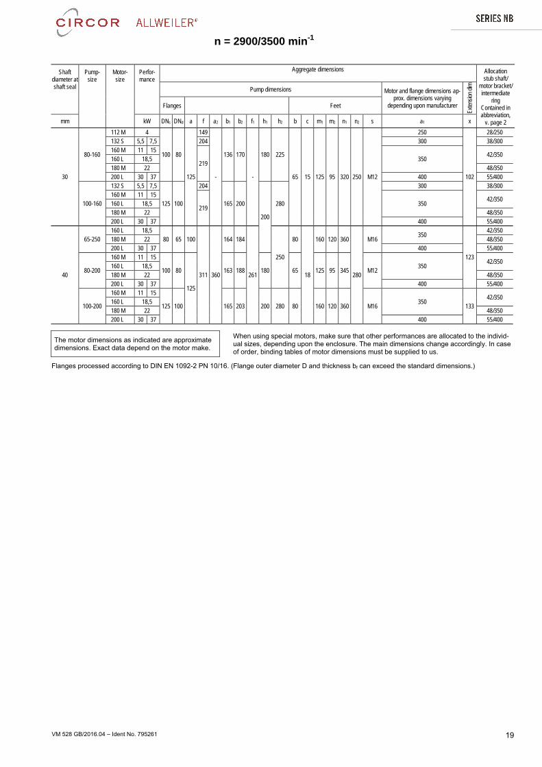
VM 528 GB/2016.04 – Ident No. 795261 19
Shaft diameter at shaft seal
Pump- size
Motor- size
Perfor- mance
Aggregate dimensions Allocation stub shaft/
motor bracket/ intermediate
ring Contained in abbreviation,
v. page 2
Pump dimensions Motor and flange dimensions ap-prox. dimensions varying
depending upon manufacturer
Exte
nsio
n di
m
Flanges Feet
mm kW DNs DNd a f a2 b1 b2 f1 h1 h2 b c m1 m2 n1 n2 s a1 x
30
80-160
112 M 4
100 80
125
149
-
136 170
-
180 225
65 15 125 95 320 250 M12
250
102
28/250 132 S 5,5 7,5 204 300 38/300 160 M 11 15
219 350
42/350 160 L 18,5 180 M 22 48/350 200 L 30 37 400 55/400
100-160
132 S 5,5 7,5
125 100
204
165 200
200
280
300 38/300 160 M 11 15
219 350
42/350 160 L 18,5 180 M 22 48/350 200 L 30 37 400 55/400
40
65-250 160 L 18,5
80 65 100
311 360
164 184
261
250
80
18
160 120 360
280
M16 350
123
42/350 180 M 22 48/350 200 L 30 37 400 55/400
80-200
160 M 11 15
100 80
125
163 188 180 65 125 95 345 M12 350
42/350 160 L 18,5 180 M 22 48/350 200 L 30 37 400 55/400
100-200
160 M 11 15
125 100 165 203 200 280 80 160 120 360 M16 350
133 42/350
160 L 18,5 180 M 22 48/350 200 L 30 37 400 55/400
The motor dimensions as indicated are approximate dimensions. Exact data depend on the motor make.
When using special motors, make sure that other performances are allocated to the individ-ual sizes, depending upon the enclosure. The main dimensions change accordingly. In case of order, binding tables of motor dimensions must be supplied to us.
Flanges processed according to DIN EN 1092-2 PN 10/16. (Flange outer diameter D and thickness bf can exceed the standard dimensions.)