GB/11.06 – Ident-No. 488 005 1 Volute Casing Centrifugal Pumps PN 16 for the purpose of fire-fighting Series NAM-F with axial inlet for pedestal mounting or wall mounting Application For handling fresh and sea water. The liquids to be pumped must not contain any abrasive particles. Main field of application In shipbuilding as fire-fighting pump. Design Single-stage, single-flow volute casing centrifugal pump. Vo- lute casing with axial inlet and radial outlet. Nominal capacities according to DIN EN 22 858 or DIN EN 733. Pump casing and bearing unit are connected with the driving motor by means of a pump bracket. Feet at the lower flange of the pump bracket allow vertical pedestal mounting. Laterally arranged consoles permit vertical wall mounting. General application of spacer couplings allows dismantling of the bearing unit including impeller without removing the volute casing, pipelines or driving motor. Aligning of the coupling is not necessary as the pump and driving motor are exactly cen- tered in the pump bracket, i.e. intermediate ring. All screw connections are by means of hexagonal head bolts and hexagonal nuts so that even after repeated painting (ship- building), proper loosening of same will be caused. Performance data Capacity Q up to 440 m 3 /h Delivery head H 80 up to 145 m Temperature t up to 90 °C Inlet pressure p s Outlet pressure p d up to 16 bar Inlet pressure plus max. delivery head must not exceed the admissible outlet pressure. Branch position and flanges Suction branch: axial Delivery branch: radial Flanges: according to DIN EN 1092-2 PN 16 Shaft coupling and safety guarding Flexible shaft coupling with spacer (spacer coupling) and safety guarding according to DIN EN 294. Shaft sealing By normed, maintenance-free mechanical seal in unbalanced design. Mechanical seal materials Rotating ring: hard carbon Stationary ring: oxide ceramics O-rings: FPM Metal parts: stainless steel Bearing and lubrication Two grease-lubricated for lifetime groove ball bearings in the bearing bracket as per DIN 625. Note: Nominal service life of bearing designed for 1000 hours operation at least. Combination of structural components The modular system allows reduced stockkeeping of spare parts. For this series, only two bearing units (shaft sizes) are required, each of them with one mechanical seal size. The table on page 2 shows the combination possibilities of structural components of all NAM-F sizes. Drive Standard by means of a three-phase motor, type of construction V1. Connections FF Filling LO Leakage outlet FV Venting PM1 Pressure gauge PM2 Pressure gauge only size 65-250/01 and 80-250/01, see also automatic aspirator page 10 Abbreviation The structure of the abbreviation of a NAM-F pump This abbreviation is entered on the nameplate. ®
Transcript
GB/11.06 – Ident-No. 488 005 1
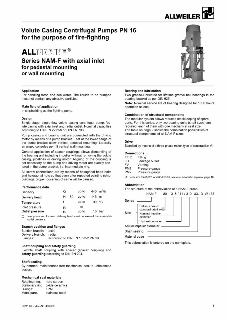
Volute Casing Centrifugal Pumps PN 16 for the purpose of fire-fighting
Series NAM-F with axial inlet for pedestal mounting or wall mounting
Application For handling fresh and sea water. The liquids to be pumped must not contain any abrasive particles.
Main field of application In shipbuilding as fire-fighting pump.
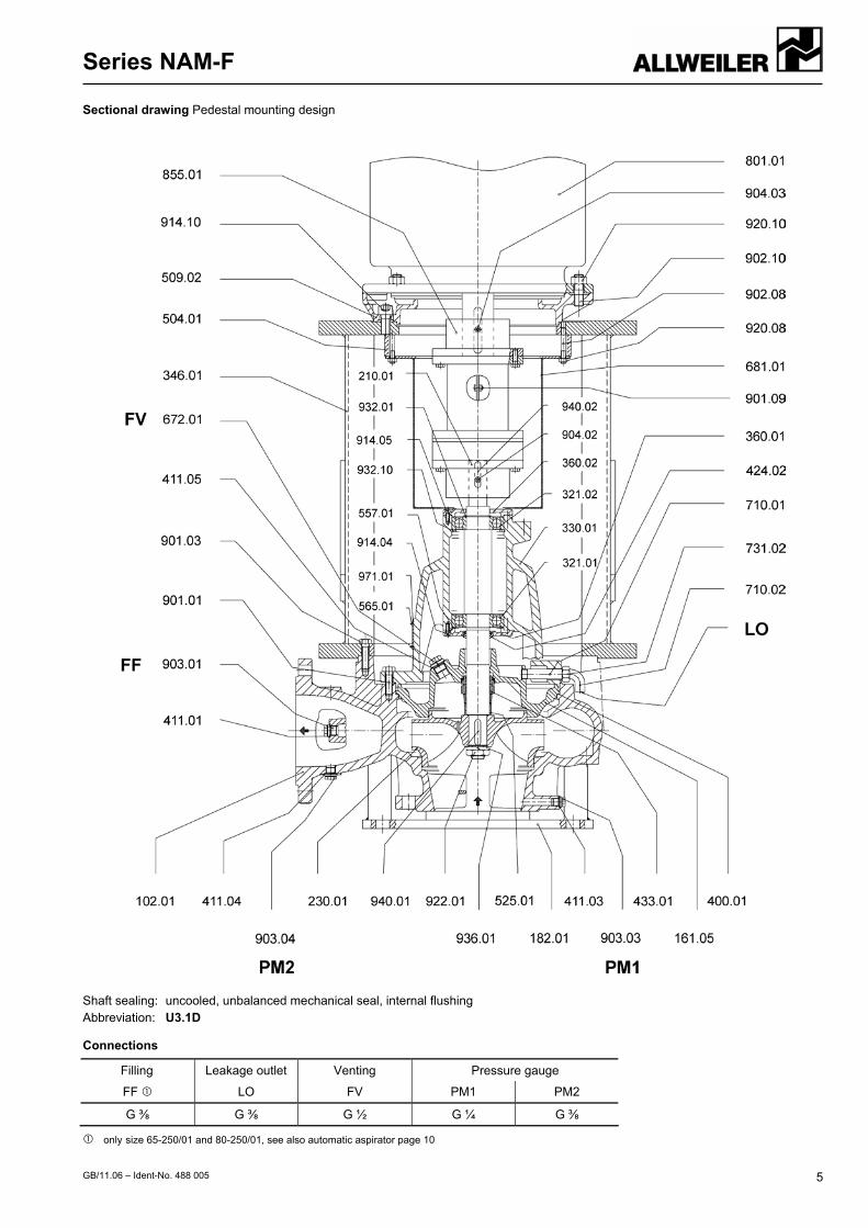
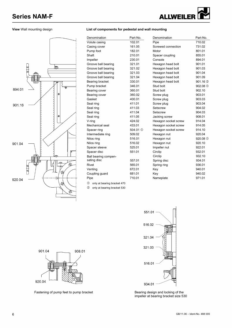
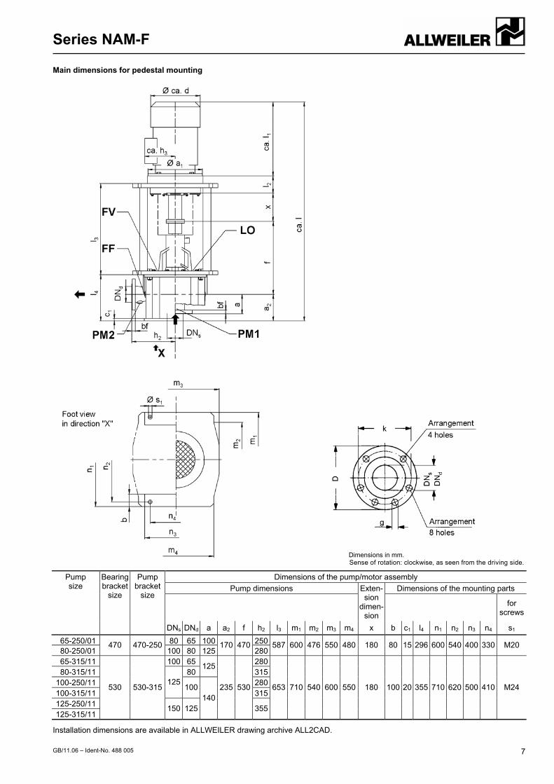
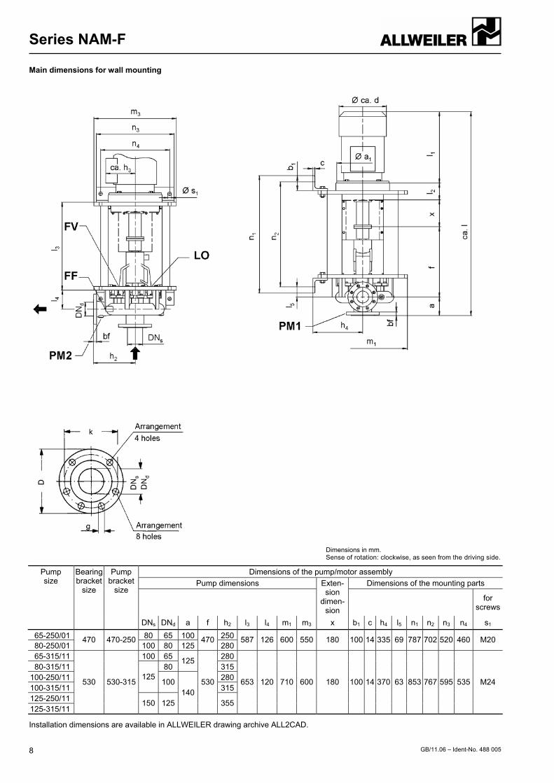
Design Single-stage, single-flow volute casing centrifugal pump. Vo-lute casing with axial inlet and radial outlet. Nominal capacities according to DIN EN 22 858 or DIN EN 733. Pump casing and bearing unit are connected with the driving motor by means of a pump bracket. Feet at the lower flange of the pump bracket allow vertical pedestal mounting. Laterally arranged consoles permit vertical wall mounting. General application of spacer couplings allows dismantling of the bearing unit including impeller without removing the volute casing, pipelines or driving motor. Aligning of the coupling is not necessary as the pump and driving motor are exactly cen-tered in the pump bracket, i.e. intermediate ring. All screw connections are by means of hexagonal head bolts and hexagonal nuts so that even after repeated painting (ship-building), proper loosening of same will be caused.
Performance data Capacity Q up to 440 m3/h
Delivery head H 80 up to 145 m
Temperature t up to 90 °C Inlet pressure ps Outlet pressure pd up to 16 bar
Inlet pressure plus max. delivery head must not exceed the admissible outlet pressure.
Branch position and flanges Suction branch: axial Delivery branch: radial Flanges: according to DIN EN 1092-2 PN 16
Shaft coupling and safety guarding Flexible shaft coupling with spacer (spacer coupling) and safety guarding according to DIN EN 294.
Shaft sealing By normed, maintenance-free mechanical seal in unbalanced design.
Mechanical seal materials Rotating ring: hard carbon Stationary ring: oxide ceramics O-rings: FPM Metal parts: stainless steel
Bearing and lubrication Two grease-lubricated for lifetime groove ball bearings in the bearing bracket as per DIN 625. Note: Nominal service life of bearing designed for 1000 hours operation at least.
Combination of structural components The modular system allows reduced stockkeeping of spare parts. For this series, only two bearing units (shaft sizes) are required, each of them with one mechanical seal size. The table on page 2 shows the combination possibilities of structural components of all NAM-F sizes.
Drive Standard by means of a three-phase motor, type of construction V1.
only size 65-250/01 and 80-250/01, see also automatic aspirator page 10
Abbreviation The structure of the abbreviation of a NAM-F pump
This abbreviation is entered on the nameplate.
®
Series NAM-F
GB/11.06 – Ident-No. 488 005 2
Materials Material code Denomination Part No.
W 133 Volute casing 102… CC333G Casing cover 161... CC333G Shaft 210... 1.4462 Impeller 230... CC333G Bearing bracket 330... EN-GJL-250 Pump bracket 346... steel welded Screws and nuts coming into con-tact with the liquid to be pumped - stainless steel
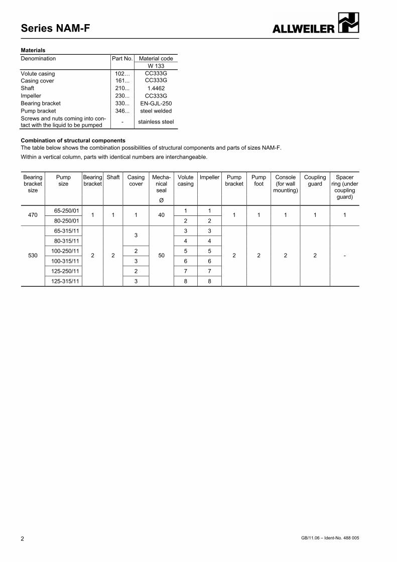
Combination of structural components The table below shows the combination possibilities of structural components and parts of sizes NAM-F. Within a vertical column, parts with identical numbers are interchangeable.
Mecha-nical seal
Bearing bracket
size
Pump size
Bearing bracket
Shaft Casing cover
Ø
Volutecasing
Impeller Pumpbracket
Pumpfoot
Console (for wall
mounting)
Coupling guard
Spacer ring (undercouplingguard)
65-250/01 1 1 470
80-250/01 1 1 1 40
2 2 1 1 1 1 1
65-315/11 3 3
80-315/11 3
4 4
100-250/11 2 5 5
100-315/11 3 6 6
125-250/11 2 7 7
530
125-315/11
2 2
3
50
8 8
2 2 2 2 -
Series NAM-F
GB/11.06 – Ident-No. 488 005 3
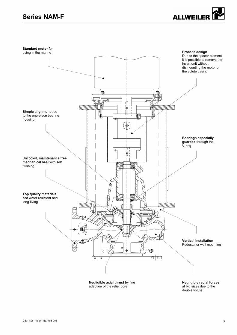
Standard motor for using in the marine
Simple alignment due to the one-piece bearing housing
Top quality materials, sea water resistant and long-living
Uncooled, maintenance free mechanical seal with self flushing
Process designDue to the spacer element it is possible to remove the insert unit without dismounting the motor or the volute casing.
Bearings especially guarded through the V-ring
Vertical installationPedestal or wall mounting
Negligible radial forces at big sizes due to the double volute
Negligible axial thrust by fine adaption of the relief bore
Series NAM-F
GB/11.06 – Ident-No. 488 005 4
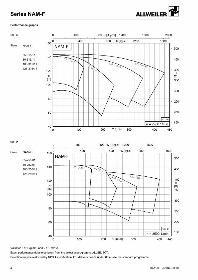
Performance graphs
50 Hz Sizes
NAM-F: 65-315/11 80-315/11 100-315/11 125-315/11
60 Hz Sizes
NAM-F: 65-250/01 80-250/01 100-250/11 125-250/11
Valid for ρ = 1 kg/dm³ and ν = 1 mm²/s. Exact performance data to be taken from the selection programme ALLSELECT. Selection may be restricted by NPSH specification. For delivery heads under 80 m see the standard programme.
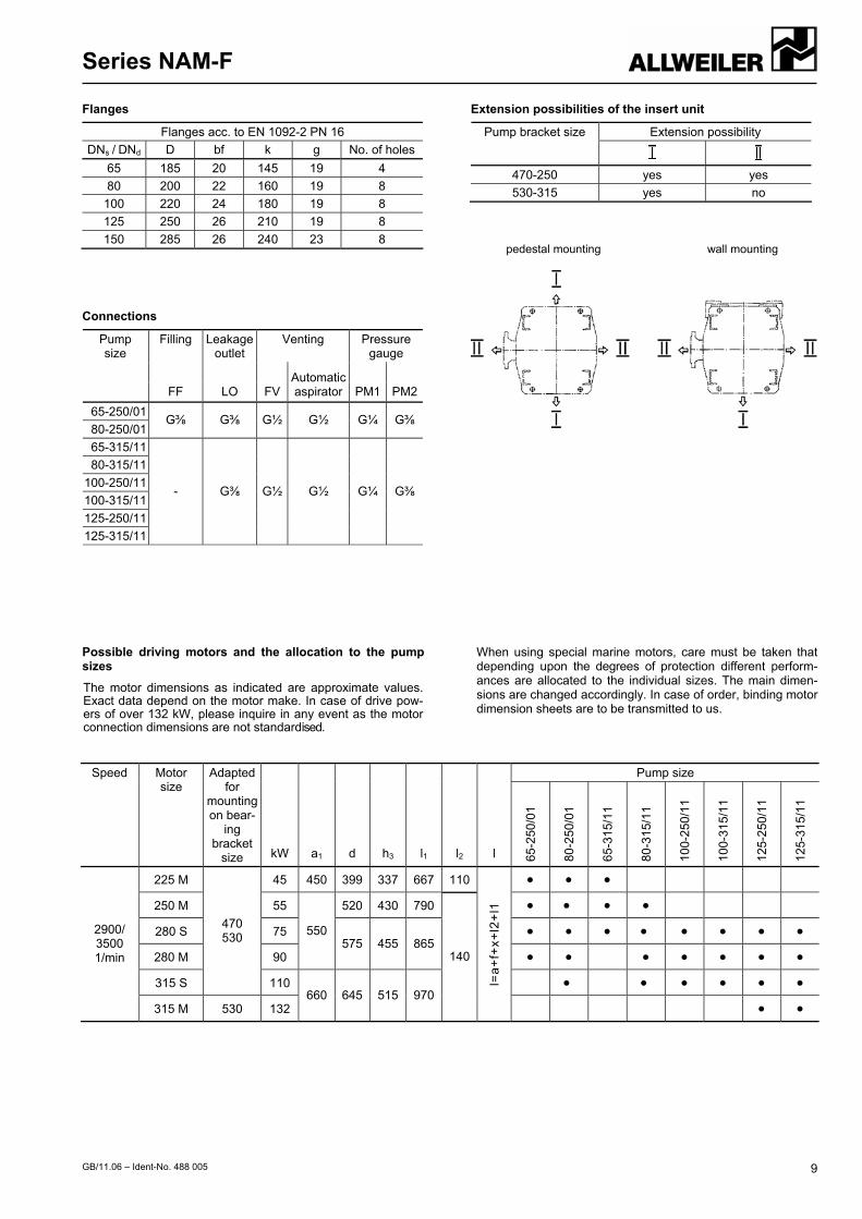
Possible driving motors and the allocation to the pump sizes
The motor dimensions as indicated are approximate values. Exact data depend on the motor make. In case of drive pow-ers of over 132 kW, please inquire in any event as the motor connection dimensions are not standardised.
When using special marine motors, care must be taken that depending upon the degrees of protection different perform-ances are allocated to the individual sizes. The main dimen-sions are changed accordingly. In case of order, binding motor dimension sheets are to be transmitted to us.
Pump size Speed Motor size
Adapted for
mounting on bear-
ing bracket
size kW a1 d h3 l1 l2 l 65-2
50/0
1
80-2
50/0
1
65-3
15/1
1
80-3
15/1
1
100-
250/
11
100-
315/
11
125-
250/
11
125-
315/
11
225 M 45 450 399 337 667 110 ● ● ●
250 M 55 520 430 790 ● ● ● ●
280 S 75 ● ● ● ● ● ● ● ●
280 M 90
550 575 455 865
● ● ● ● ● ● ●
315 S
470 530
110 ● ● ● ● ● ●
2900/ 3500 1/min
315 M 530 132 660 645 515 970
140
l=a+
f+x+
l2+l
1
● ●
Series NAM-F
GB/11.06 – Ident-No. 488 005 10
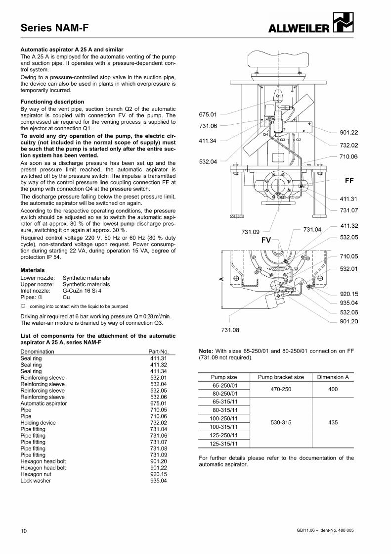
Automatic aspirator A 25 A and similar The A 25 A is employed for the automatic venting of the pump and suction pipe. It operates with a pressure-dependent con-trol system. Owing to a pressure-controlled stop valve in the suction pipe, the device can also be used in plants in which overpressure is temporarily incurred.
Functioning description By way of the vent pipe, suction branch Q2 of the automatic aspirator is coupled with connection FV of the pump. The compressed air required for the venting process is supplied to the ejector at connection Q1. To avoid any dry operation of the pump, the electric cir-cuitry (not included in the normal scope of supply) must be such that the pump is started only after the entire suc-tion system has been vented. As soon as a discharge pressure has been set up and the preset pressure limit reached, the automatic aspirator is switched off by the pressure switch. The impulse is transmitted by way of the control pressure line coupling connection FF at the pump with connection Q4 at the pressure switch. The discharge pressure falling below the preset pressure limit, the automatic aspirator will be switched on again. According to the respective operating conditions, the pressure switch should be adjusted so as to switch the automatic aspi-rator off at approx. 80 % of the lowest pump discharge pres-sure, switching it on again at approx. 30 %. Required control voltage 220 V, 50 Hz or 60 Hz (80 % duty cycle), non-standard voltage upon request. Power consump-tion during starting 22 VA, during operation 15 VA, degree of protection IP 54.
Materials Lower nozzle: Synthetic materials Upper nozze: Synthetic materials Inlet nozzle: G-CuZn 16 Si 4 Pipes: Cu
coming into contact with the liquid to be pumped
Driving air required at 6 bar working pressure Q = 0.28 m3/min. The water-air mixture is drained by way of connection Q3.
List of components for the attachment of the automatic aspirator A 25 A, series NAM-F
Denomination Part-No. Seal ring 411.31 Seal ring 411.32 Seal ring 411.34 Reinforcing sleeve 532.01 Reinforcing sleeve 532.04 Reinforcing sleeve 532.05 Reinforcing sleeve 532.06 Automatic aspirator 675.01 Pipe 710.05 Pipe 710.06 Holding device 732.02 Pipe fitting 731.04 Pipe fitting 731.06 Pipe fitting 731.07 Pipe fitting 731.08 Pipe fitting 731.09 Hexagon head bolt 901.20 Hexagon head bolt 901.22 Hexagon nut 920.15 Lock washer 935.04
Note: With sizes 65-250/01 and 80-250/01 connection on FF (731.09 not required).
Pump size Pump bracket size Dimension A 65-250/01 80-250/01
470-250 400
65-315/11 80-315/11
100-250/11 100-315/11 125-250/11 125-315/11
530-315 435
For further details please refer to the documentation of the automatic aspirator.
ALLWEILER Solutions
GB/11.06 – Ident-No. 488 005 11
Successful in important branches
Decades of experience and branch-specific know-how ensure solutions that are practical and dependable. In addition to individual units with a motor or with a free shaft end, you can get complete systems and customer-specific cast parts from ALLWEILER AG. You are not just investing in machines with ALLWEILER AG. You are also profiting from decades of know-how about applications and processes in your branch.
You will find pumps and systems by ALLWEILER AG in the following sectors:
Marine and Offshore Made of particularly corrosion-resistant, saltwater-proof materials and in accordance with specific standards (shock testing, national marine, international classifications, etc.).
Power Generation Block and twin units for fuel and water injection in gas and steam turbines. For fuel supply, injection and lubricating oil delivery in power plants.
Water and Wastewater Pumps for water treatment; share of dry solids content up to 45 %; macerators, which make it possible to pump de-livery media that are high in fibre and solids.
Biofuels Materials resistant to aggressive intermediate and final products. Pumps for every step in the process.
Process Engineering and Chemistry (ATEX-conformity)
Shaft bearing, shaft seal and material designs in accor-dance with the chemical characteristics of the delivery me-dia. Magnetic coupling for hermetically sealed pumps.
Oil and Gas Pumps with a wide viscosity range, high pressure and large capacity.
Building Industry Special units for oil furnace and lift systems. Oil submersi-ble pumps for all types of hydraulic machines.
Food and Pharma Stainless steel pumps with CIP and SIP design, EHEDG and FDA certified. Especially for the careful delivery and proportioning of even sticky, paste-like and solids-rich media.
Tool Machinery Designed for large capacity or a high discharge pressure; resistant to contaminants and foreign materials. Especially for cooling lubricant supply.
Pulp and Paper Pumps with extremely high availability (24 hours; 365 days) and many sizes, starting with small proportioning pumps and ranging to large Kaolin feeding pumps.
Heat Transfer In supply circuits, circulating systems and heating circuits for the delivery of hot water and heat-transfer oil up to 207 °C and 450 °C.
The mentioned performance data and additionally all standard refer-ences are to be considered as a product and performance abstract only. The particular operating limits can be taken from the quotation or order acknowledgement.