Dieses Dokument beschreibt die integrierte Grundrissprogrammierung des CGLine+ Web-Controllers, die im Menu “Grundrisspläne” abrufbar ist. Diese Funktion erlaubt eine graphische Statusanzeige der Leuchten auf bis zu 30 Grundrissplänen.
Die Quelldaten müssen als Grundrisspläne im AutoCAD-Format vorliegen. Die Erstellung der Zieldateien erfolgt in 4 Schritten:
OO Erfassen der Pläne
OO Konvertieren in SVG
OO Analyse der Pläne
OO Hinzufügen der Pläne zur Zentrale
Diese vier Schritte sind notwendig, damit die Pläne konvertiert und im CGLine+ Web-Controller installiert werden können. Sie müssen nur ein einziges Mal durchgeführt werden.
2. Erfassen der Pläne
In diesem ersten Schritt werden zunächst sämtliche Pläne des Standorts von der AutoCAD-Software erfasst.
EingabedateiDie Eingabedateien müssen AutoCAD-Pläne sein (Version oder Format spielen keine Rolle).
AusgabedateiDie Ausgabedateien müssen kleiner als 5 MB sein und dürfen nicht mehr als 200 Blöcke enthalten. Sie werden im DXF-Format (Version 2000) abgespeichert.
Um die 5-MB-Grenze für Ausgabepläne nicht zu überschreiten, kann es notwendig sein, eine „Bereinigung“ der Pläne durchzuführen (Entfernen grafischer Elemente und/oder Zerlegen der Pläne).
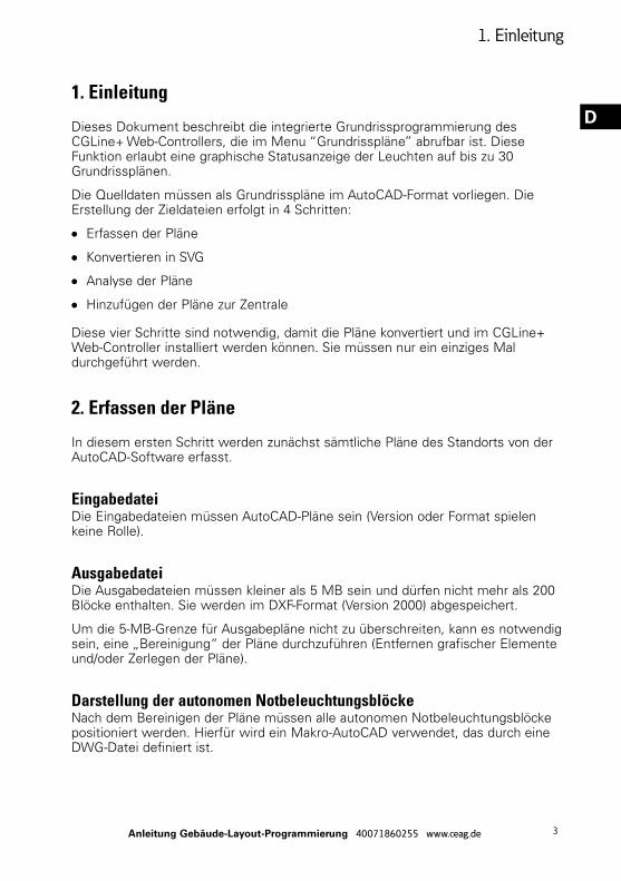
Darstellung der autonomen NotbeleuchtungsblöckeNach dem Bereinigen der Pläne müssen alle autonomen Notbeleuchtungsblöcke positioniert werden. Hierfür wird ein Makro-AutoCAD verwendet, das durch eine DWG-Datei definiert ist.
Die Makro-AutoCAD-Datei enthält folgende Informationen:
OO 1. Definition der Leuchtenposition im grünen Rechteck mit der Bezeichnung “BAES”
OO 2. Definition der Leuchtenadresse mit folgendem Aufbau:
OO Controller-Nr., z.B. C1
OO Strang-Nr. (Line), z.B. L1
OO Zonen-Nr., z.B. Z3
OO Leuchtenadresse (Block), z.B. B73
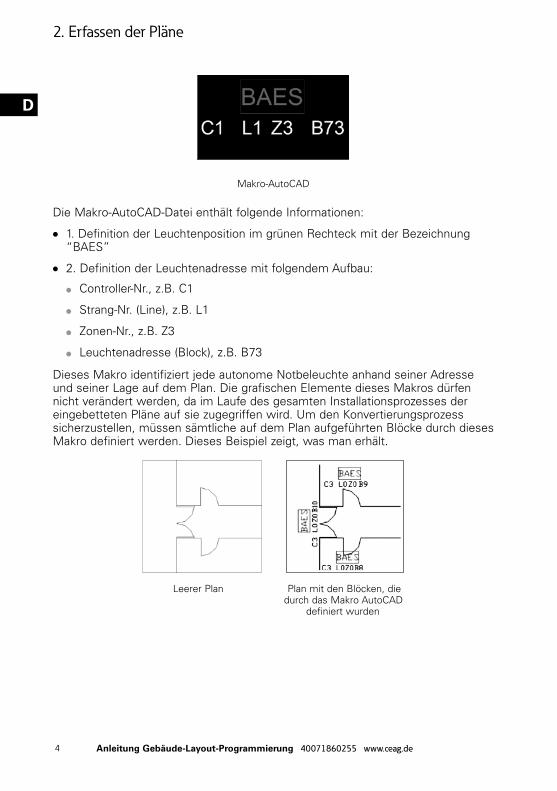
Dieses Makro identifiziert jede autonome Notbeleuchte anhand seiner Adresse und seiner Lage auf dem Plan. Die grafischen Elemente dieses Makros dürfen nicht verändert werden, da im Laufe des gesamten Installationsprozesses der eingebetteten Pläne auf sie zugegriffen wird. Um den Konvertierungsprozess sicherzustellen, müssen sämtliche auf dem Plan aufgeführten Blöcke durch dieses Makro definiert werden. Dieses Beispiel zeigt, was man erhält.
Leerer Plan Plan mit den Blöcken, die durch das Makro AutoCAD definiert wurden
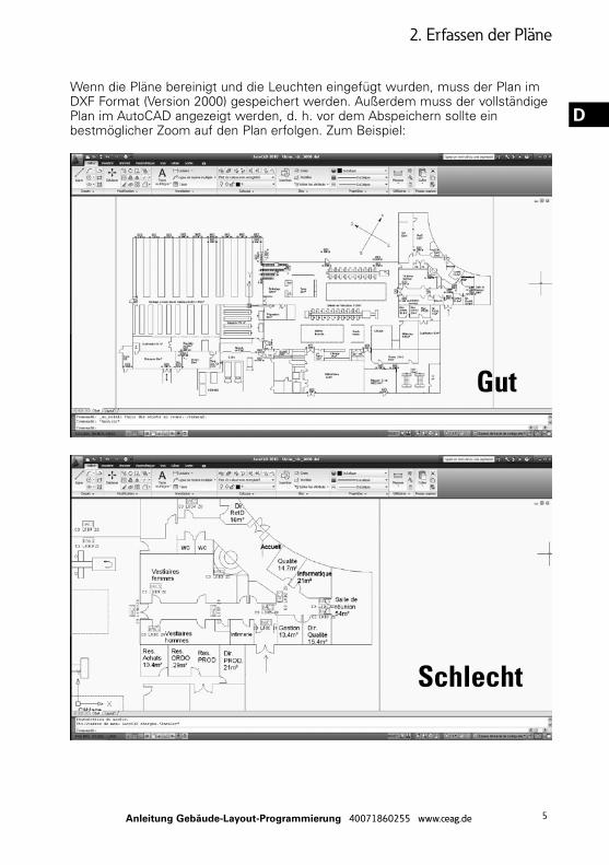
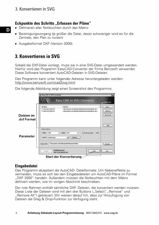
Wenn die Pläne bereinigt und die Leuchten eingefügt wurden, muss der Plan im DXF Format (Version 2000) gespeichert werden. Außerdem muss der vollständige Plan im AutoCAD angezeigt werden, d. h. vor dem Abspeichern sollte ein bestmöglicher Zoom auf den Plan erfolgen. Zum Beispiel:
DEckpunkte des Schritts „Erfassen der Pläne“OO Definieren aller Notleuchten durch das Makro
OO Bereinigungsvorgang (je größer die Datei, desto schwieriger wird es für die Zentrale, den Plan zu nutzen)
OO Ausgabeformat DXF (Version 2000).
3. Konvertieren in SVG
Sobald die DXF-Datei vorliegt, muss sie in eine SVG-Datei umgewandelt werden. Hierfür wird das Programm EasyCAD-Converter der Firma Benzsoft verwendet. Diese Software konvertiert AutoCAD-Dateien in SVG-Dateien.
Das Programm kann unter folgender Adresse heruntergeladen werden: http://www.benzsoft.com/cad2svg.html
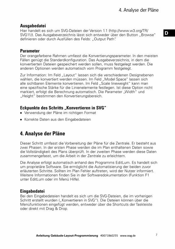
Die folgende Abbildung zeigt einen Screenshot des Programms.
EingabedateiDas Programm akzeptiert die AutoCAD- Dateiformate. Um Nebeneffekte zu vermeiden, muss es sich bei den Eingabedateien um AutoCAD-Pläne im Format „DXF 2000“ handeln. Außerdem müssen die Notleuchten mit dem Makro definiert werden, wie im vorigen Abschnitt beschrieben.
Der rote Rahmen enthält sämtliche DXF- Dateien, die konvertiert werden müssen. Diese Liste der Dateien wird mit den drei Buttons („Select“, „Remove“ und „Remove All“) gesteuert. Wir weisen darauf hin, dass zur Hinzufügung von Dateien die Drag & Drop-Funktion zur Verfügung steht.
DAusgabedateiHier handelt es sich um SVG-Dateien der Version 1.1 (http://www.w3.org/TR/SVG11/). Das Ausgabeverzeichnis lässt sich entweder über den Button „Browse“ definieren oder durch Ausfüllen des Felds: „Output Path“.
Parameter Der orangefarbene Rahmen umfasst die Konvertierungsparameter. In den meisten Fällen genügt die Standardkonfiguration. Das Ausgabeverzeichnis, in dem die konvertierten Dateien gespeichert werden sollen, muss festgelegt werden. Die anderen Optionen werden automatisch vom Programm festgelegt.
Zur Information: Im Feld „Layout“ lassen sich die verschiedenen Designebenen wählen, die konvertiert werden müssen. Im Feld „Model Space“ lassen sich alle sichtbaren Elemente konvertieren. Im Feld „Scale lineweight“ kann man eine spezifische Stärke für die Linienelemente festlegen. Ist diese Option nicht markiert, erfolgt die Berechnung automatisch. Die Parameter „Width“ und „Height“ bestimmen den Konvertierungsbereich.
Eckpunkte des Schritts „Konvertieren in SVG“OO Verwendung der Pläne im richtigen Format
OO Korrekte Daten aus den Eingabedateien
4. Analyse der Pläne
Dieser Schritt umfasst die Vorbereitung der Pläne für die Zentrale. Er besteht aus zwei Phasen. In der ersten Phase werden die im Plan enthaltenen Daten sowie die Vollständigkeit des Plans überprüft. In der zweiten Phase werden diese Daten zusammengefasst, um die Arbeit in der Zentrale zu erleichtern.
Die Analyse erfolgt automatisch anhand des Programms EditLum. Es handelt sich um proprietäre Software. Sie ermöglicht die Automatisierung der beiden zuvor erläuterten Schritte. Sollten im Plan Fehler auftreten, wird der Nutzer informiert. Weitere Informationen finden Sie in der Softwaredokumentation (Funktion F1 unter EditLum oder im Menü Hilfe).
EingabedateiBei den Eingabedateien handelt es sich um die SVG-Dateien, die im vorherigen Schritt erstellt wurden („Konvertieren in SVG“). Die Dateien können über die Menüfunktionen eingefügt werden, entweder über die Shortcuts der Taskleiste oder direkt mit Drag & Drop.
AusgabedateiDas Programm generiert eine XML-Datei desselben Namens für jede festgelegte SVG-Datei. In dieser Datei befinden sich die in der SVG-Datei enthaltenen Informationen, sowie eine Zusammenfassung am Datei-Anfang und ein Bearbeitungsbereich am Datei-Ende.
Zusammenfassung der MethodeOO Einfügen der verschiedenen SVG-Pläne in die EditLum Software (optional
erhältlich).
OO Analyse starten.
OO Ausgabeverzeichnis angeben.
OO Die Analyse läuft automatisch ab. Es erscheint eine Meldung mit dem Endergebnis (Analyse erfolgreich durchgeführt oder fehlgeschlagen).
5. Hinzufügen der Pläne zur Zentrale
Dieser letzte Schritt dient dem Hinzufügen der in EditLum erstellten Pläne in die Zentrale CGLine+ web controller.
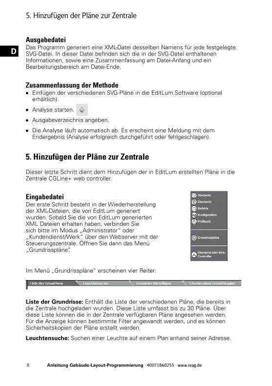
EingabedateiDer erste Schritt besteht in der Wiederherstellung der XML-Dateien, die von EditLum generiert wurden. Sobald Sie die von EditLum generierten XML Dateien erhalten haben, verbinden Sie sich bitte im Modus „Administrator“ oder „Kundendienst/Werk“ über den Webserver mit der Steuerungszentrale. Öffnen Sie dann das Menü „Grundrisspläne“.
Im Menü „Grundrisspläne“ erscheinen vier Reiter:
Liste der Grundrisse: Enthält die Liste der verschiedenen Pläne, die bereits in die Zentrale hochgeladen wurden. Diese Liste umfasst bis zu 30 Pläne. Über diese Liste können die in der Zentrale verfügbaren Pläne angesehen werden. Für die Anzeige können bestimmte Filter angewandt werden, und es können Sicherheitskopien der Pläne erstellt werden.
Leuchtensuche: Suchen einer Leuchte auf einem Plan anhand seiner Adresse.
Grundriss hinzufügen: Hinzufügen eines Plans zur Liste der in der Zentrale verfügbaren Pläne.
Lösche einen Grundrissplan: Löschen eines Plans der Liste der in der Zentrale verfügbaren Pläne.
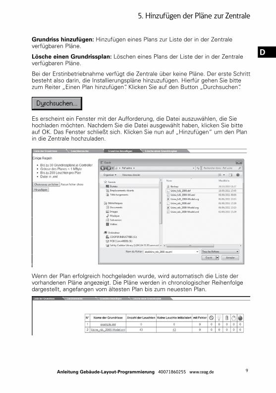
Bei der Erstinbetriebnahme verfügt die Zentrale über keine Pläne. Der erste Schritt besteht also darin, die Installierungspläne hinzuzufügen. Hierfür gehen Sie bitte zum Reiter „Einen Plan hinzufügen“. Klicken Sie auf den Button „Durchsuchen“.
Es erscheint ein Fenster mit der Aufforderung, die Datei auszuwählen, die Sie hochladen möchten. Nachdem Sie die Datei ausgewählt haben, klicken Sie bitte auf OK. Das Fenster schließt sich. Klicken Sie nun auf „Hinzufügen“ um den Plan in die Zentrale hochzuladen.
Wenn der Plan erfolgreich hochgeladen wurde, wird automatisch die Liste der vorhandenen Pläne angezeigt. Die Pläne werden in chronologischer Reihenfolge dargestellt, angefangen vom ältesten Plan bis zum neuesten Plan.
Jeder Plan enthält folgende Informationen:OO Eine Kennnummer
OO Einen Namen
OO Anzahl der auf dem Plan eingezeichneten Leuchten
OO Anzahl der defekten Leuchten
OO Filtereinstellungen für die Anzeige (Leuchte fehlt, Lampe defekt, Batterie defekt, Mangel ermittelt bei Funktions- und Betriebsdauertest)
OO Datum des letzten Speichervorgangs und die Möglichkeit, den Plan auf einem Computer zu speichern
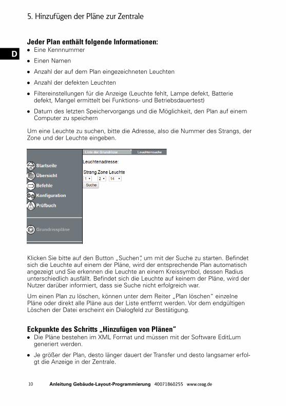
Um eine Leuchte zu suchen, bitte die Adresse, also die Nummer des Strangs, der Zone und der Leuchte eingeben.
Klicken Sie bitte auf den Button „Suchen“, um mit der Suche zu starten. Befindet sich die Leuchte auf einem der Pläne, wird der entsprechende Plan automatisch angezeigt und Sie erkennen die Leuchte an einem Kreissymbol, dessen Radius unterschiedlich ausfällt. Befindet sich die Leuchte auf keinem der Pläne, wird der Nutzer darüber informiert, dass sie Suche nicht erfolgreich war.
Um einen Plan zu löschen, können unter dem Reiter „Plan löschen“ einzelne Pläne oder direkt alle Pläne aus der Liste entfernt werden. Vor dem endgültigen Löschen der Datei erscheint ein Dialogfeld zur Bestätigung.
Eckpunkte des Schritts „Hinzufügen von Plänen“OO Die Pläne bestehen im XML Format und müssen mit der Software EditLum
generiert werden.
OO Je größer der Plan, desto länger dauert der Transfer und desto langsamer erfol-gt die Anzeige in der Zentrale.
1) Die Statuspunkte der Notleuchte werden auf dem Plan nicht angezeigt.Überprüfen, ob die Zentrale-Nummern der Leuchte im Schema wirklich mit der Nummer des Controllers übereinstimmen, in der die Pläne aufgerufen werden. Ist dies nicht der Fall, werden die Punkte nicht angezeigt.
2) Die Suche nach einer Leuchte liefert kein Ergebnis, obwohl sich die Leuchte auf dem Plan befindet.
Damit die Suche ein Ergebnis liefern kann, müssen folgende Bedingungen erfüllt sein:
OO Die Leuchte muss sich auf dem Plan befinden.
OO Die Zentrale-Nummer der Leuchte auf dem Plan muss mit der Nummer der Zentrale übereinstimmen, von der aus die Suche gestartet wird.
OO Die Leuchte muss zuvor dem Controller hinzugefügt worden sein, und zwar über die Initialisierungsfunktion des Controllers.
3) Das Anzeigen der Pläne dauert zu lange.Damit die Pläne schnell angezeigt werden können, wird empfohlen, Pläne zu verwenden, die kleiner als 1 MB sind.
This document describes how to use the “Embedded Plans” functionality on the CGLine+ Web-Controller self-contained emergency lighting units control interface.
The “Embedded Plans” functionality enables you to view the current installation status on plans which are displayed in an HTML page, through a web server embedded in the control interface. To implement this functionality, you must follow four steps:
OO Input plans
OO Convert to SVG
OO Analyse plans
OO Load plans onto the control interface
These four steps allow the plans to be converted and installed on the control interface. They only need to be completed once. Once these four steps have been completed, the user only requires a web browser and the CGLine+ web controller interface.
2. Input plans
This first step involves inputting all site plans into AutoCAD software.
Input fileThe input files must be AutoCAD plans (no restriction on version or format).
Output fileThe output files must be smaller than 5MB and contain fewer than 200 units. They are saved in DXF format (version 2000).
In order to respect the 5MB restriction for the output files, it may be necessary to “purify” the plans (delete graphics and/or crop the plans).
Representation of the emergency lighting units Once the plans have been purified, the units must be positioned. To do this, we use an AutoCAD macro defined by a DWG file.
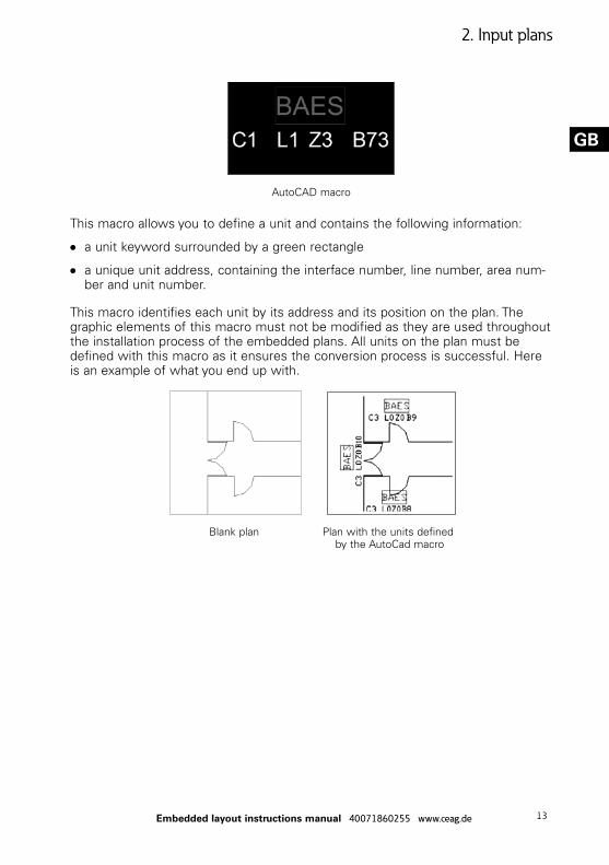
This macro allows you to define a unit and contains the following information:
OO a unit keyword surrounded by a green rectangle
OO a unique unit address, containing the interface number, line number, area num-ber and unit number.
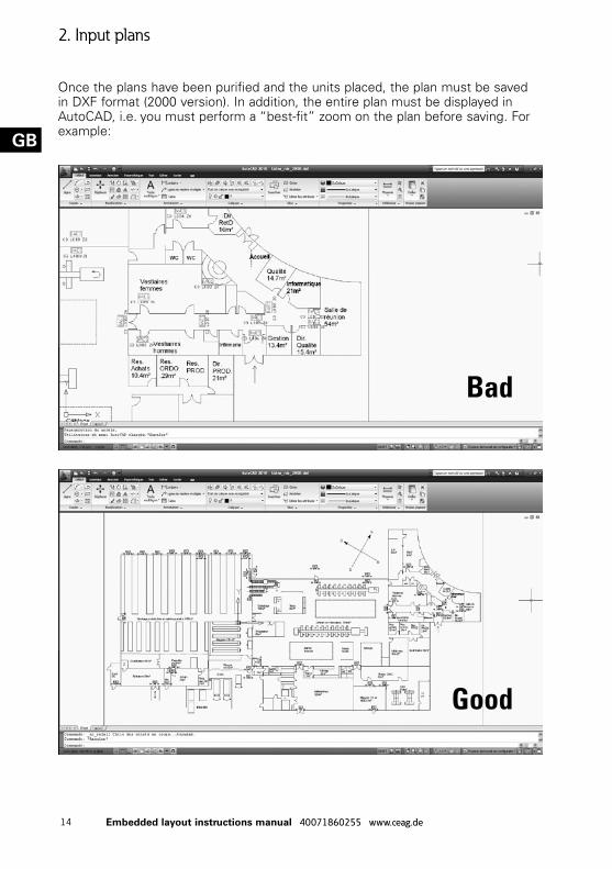
This macro identifies each unit by its address and its position on the plan. The graphic elements of this macro must not be modified as they are used throughout the installation process of the embedded plans. All units on the plan must be defined with this macro as it ensures the conversion process is successful. Here is an example of what you end up with.
Blank plan Plan with the units defined by the AutoCad macro
Once the plans have been purified and the units placed, the plan must be saved in DXF format (2000 version). In addition, the entire plan must be displayed in AutoCAD, i.e. you must perform a “best-fit” zoom on the plan before saving. For example:
Key points of the “Input Plans” processOO Define all emergency lighting units using the macro
OO Purification (the larger the file size, the more difficult the plan will be for the interface to use)
OO DXF output format (2000 version)
3. Convert to SVG
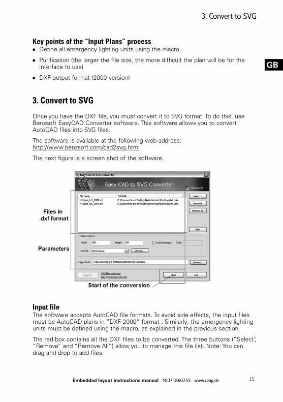
Once you have the DXF file, you must convert it to SVG format. To do this, use Benzsoft EasyCAD Converter software. This software allows you to convert AutoCAD files into SVG files.
The software is available at the following web address: http://www.benzsoft.com/cad2svg.html
The next figure is a screen shot of the software.
Input fileThe software accepts AutoCAD file formats. To avoid side effects, the input files must be AutoCAD plans in “DXF 2000” format . Similarly, the emergency lighting units must be defined using the macro, as explained in the previous section.
The red box contains all the DXF files to be converted. The three buttons (“Select”, “Remove” and “Remove All”) allow you to manage this file list. Note: You can drag and drop to add files.
Output fileThese are SVG version 1.1 files (http://www.w3.org/TR/SVG11/). You can define the output directory via the “Browse” button or by completing the “Output Path” field.
Parameters The orange box contains the conversion parameters. The default configuration is the appropriate one in the majority of cases. You must specify the output directory where the converted files will be saved. The other options are determined automatically by the software.
For information, the “Layout” field allows you to choose the various drawing layers to be converted. “Model Space” enables you to convert all visual elements. “Scale lineweight” allows you to specify a specific width for line elements. If this option is unchecked, the calculation is done automatically. The “Width” and “Height” parameters determine the conversion area.
Key points of the “Convert to SVG” processOO Use of plans in the appropriate format
OO Correct input file data
4. Analyse plans
This step will prepare the plans for the interface. It is composed of two phases. The first consists of checking the data contained within the plan and checking its integrity. The second phase is the creation of a synthesis of the data to facilitate the work of the interface.
This analysis is performed automatically by the EditLum software. This is a proprietary software. It allows the two steps described above to be automated. If there is an error in the plan, the user is informed. For more details, please refer to the software documentation (key F1 in EditLum or see the Help menu).
Input fileThe input files are the SVG files obtained in the previous step (“Convert to SVG”). You can load the files via the menus, a shortcut on the toolbar or directly by dragging and dropping.
Output fileFor each SVG file specified, the software generates an XML file with the same name as the SVG file. This file contains the information contained in the SVG file, a summary at the start of the file and editing space at the end of the file.
Summary of the methodOO Load the various SVG plans in the EditLum software.
OO Launch the analysis.
OO Indicate the output directory.
OO The analysis is automatic. A window informs you of the final result (success or failure of the analysis).
5. Load plans onto the interface
This last step allows you to load the plans obtained by EditLum onto the CGLine+ web controller interface.
Input fileThe first step is to retrieve the XML files generated by EditLum. Once you have the XML files generated by EditLum, log in to the control interface as an “Administrator” or in “After-Sales/Factory” mode via the web server and go to the “Plans” menu.
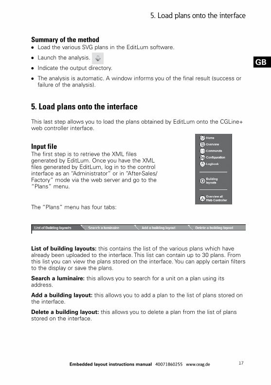
The “Plans” menu has four tabs:
List of building layouts: this contains the list of the various plans which have already been uploaded to the interface. This list can contain up to 30 plans. From this list you can view the plans stored on the interface. You can apply certain filters to the display or save the plans.
Search a luminaire: this allows you to search for a unit on a plan using its address.
Add a building layout: this allows you to add a plan to the list of plans stored on the interface.
Delete a building layout: this allows you to delete a plan from the list of plans stored on the interface.
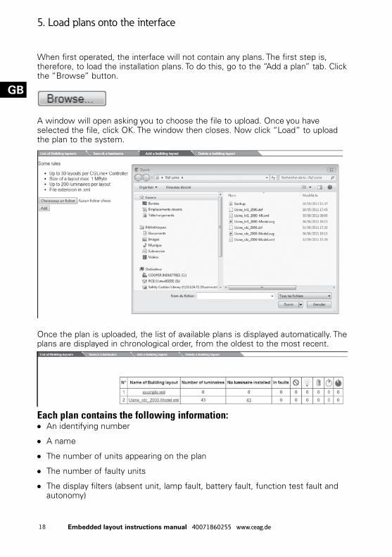
When first operated, the interface will not contain any plans. The first step is, therefore, to load the installation plans. To do this, go to the “Add a plan” tab. Click the “Browse” button.
A window will open asking you to choose the file to upload. Once you have selected the file, click OK. The window then closes. Now click “Load” to upload the plan to the system.
Once the plan is uploaded, the list of available plans is displayed automatically. The plans are displayed in chronological order, from the oldest to the most recent.
Each plan contains the following information:OO An identifying number
OO A name
OO The number of units appearing on the plan
OO The number of faulty units
OO The display filters (absent unit, lamp fault, battery fault, function test fault and autonomy)
OO Date of last save and the opportunity to save the plan to a computer
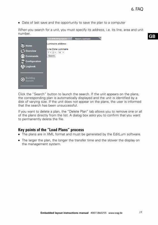
When you search for a unit, you must specify its address, i.e. its line, area and unit number.
Click the “Search” button to launch the search. If the unit appears on the plans, the corresponding plan is automatically displayed and the unit is identified by a disk of varying size. If the unit does not appear on the plans, the user is informed that the search has been unsuccessful.
If you want to delete a plan, the “Delete Plan” tab allows you to remove one or all of the plans directly from the list. A dialog box asks you to confirm that you want to permanently delete the file.
Key points of the “Load Plans” processOO The plans are in XML format and must be generated by the EditLum software.
OO The larger the plan, the longer the transfer time and the slower the display on the management system.
1) The emergency lighting unit status points are not displayed on the plan.Check that the interface numbers for the units in the diagram correspond to those on the interface on which the plans are viewed. If this is not the case, the points will not be displayed.
2) The unit search returns no results when the unit is present on the plan.In order for the search to return a result, the following conditions must all be assured:
OO The unit must appear on the plan.
OO The unit’s interface number on the plan must correspond with the interface on which the search is run.
OO The unit must have been connected to the system using its initialisation func-tion.
3) Displaying the plans is a slow process.For a more rapid display, it is better to have plans which are smaller than 1 MB in size.
6. FAQ
21Notice plans embarqués 40071860255 www.ceag.de
F
1. Introduction
Ce document décrit l’utilisation de la fonctionnalité « Plans embarqués » sur la centrale de gestion de blocs autonomes d’éclairage de sécurité CGLine+ Web-Controller.
La fonctionnalité « Plans embarqués » permet de visualiser, par l’intermédiaire d’un serveur web embarqué dans la centrale, l’état courant de l’installation sur des plans affichés dans une page HTML. Pour mettre en œuvre cette fonctionnalité, il faut respecter quatre étapes :
OO Saisie des plans
OO Conversion en SVG
OO Analyse des plans
OO Ajout des plans dans la centrale
Ces quatre étapes permettent de convertir et d’installer les plans dans la centrale. Elles ne sont à réaliser qu’une seule fois. Une fois ces quatre étapes réalisées, l’utilisateur a seulement besoin d’un navigateur web et de la centrale CGLine+ web controller.
2. Saisie des plans
Cette première étape consiste à saisir l’ensemble des plans du site sous le logiciel AutoCAD.
Fichier d’entréeLes fichiers d’entrée doivent être des plans AutoCAD (aucune contrainte sur la version ou le format).
Fichier de sortieLes fichiers de sortie doivent avoir une taille inférieure à 5 Mo, contenir moins de 200 blocs. Ils sont sauvegardés dans le format DXF (version 2000).
Afin de respecter la contrainte de 5 Mo sur les plans de sortie, il est possible qu’un travail de « purification » des plans soit nécessaire (suppression d’éléments graphiques et/ou découpe des plans).
Représentation des BAESUne fois les plans épurés, il faut positionner l’ensemble des BAES. Pour cela, on utilise une macro AutoCAD définie par un fichier DWG.
1. Introduction
22 Notice plans embarqués 40071860255 www.ceag.de
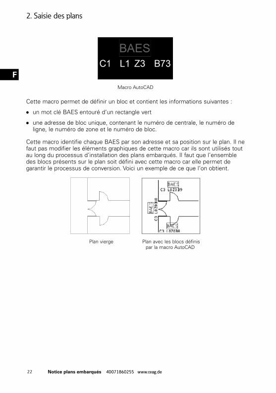
FMacro AutoCAD
Cette macro permet de définir un bloc et contient les informations suivantes :
OO un mot clé BAES entouré d’un rectangle vert
OO une adresse de bloc unique, contenant le numéro de centrale, le numéro de ligne, le numéro de zone et le numéro de bloc.
Cette macro identifie chaque BAES par son adresse et sa position sur le plan. Il ne faut pas modifier les éléments graphiques de cette macro car ils sont utilisés tout au long du processus d’installation des plans embarqués. Il faut que l’ensemble des blocs présents sur le plan soit défini avec cette macro car elle permet de garantir le processus de conversion. Voici un exemple de ce que l’on obtient.
Plan vierge Plan avec les blocs définis par la macro AutoCAD
2. Saisie des plans
23Notice plans embarqués 40071860255 www.ceag.de
F
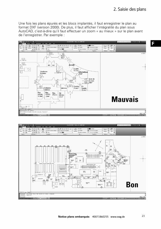
Une fois les plans épurés et les blocs implantés, il faut enregistrer le plan au format DXF (version 2000). De plus, il faut afficher l’intégralité du plan sous AutoCAD, c’est-à-dire qu’il faut effectuer un zoom « au mieux » sur le plan avant de l’enregistrer. Par exemple :
Mauvais
Bon
2. Saisie des plans
24 Notice plans embarqués 40071860255 www.ceag.de
F
Points clés de l’étape « Saisie des plans »OO Définir tous les BAES avec la macro
OO Travail d’épuration (plus le fichier aura une taille importante plus le plan sera dif-ficile à utiliser pour la centrale)
OO Format de sortie DXF (version 2000).
3. Conversion en SVG
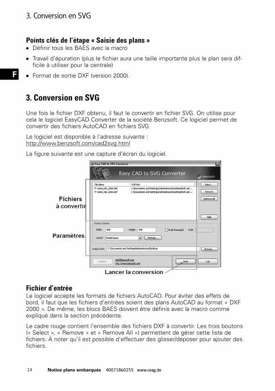
Une fois le fichier DXF obtenu, il faut le convertir en fichier SVG. On utilise pour cela le logiciel EasyCAD Converter de la société Benzsoft. Ce logiciel permet de convertir des fichiers AutoCAD en fichiers SVG.
Le logiciel est disponible à l’adresse suivante : http://www.benzsoft.com/cad2svg.html
La figure suivante est une capture d’écran du logiciel.
Fichier d’entréeLe logiciel accepte les formats de fichiers AutoCAD. Pour éviter des effets de bord, il faut que les fichiers d’entrées soient des plans AutoCAD au format « DXF 2000 ». De même, les blocs BAES doivent être définis avec la macro comme expliqué dans la section précédente.
Le cadre rouge contient l’ensemble des fichiers DXF à convertir. Les trois boutons (« Select », « Remove » et « Remove All ») permettent de gérer cette liste de fichiers. À noter qu’il est possible d’effectuer des glisser/déposer pour ajouter des fichiers.
3. Conversion en SVG
25Notice plans embarqués 40071860255 www.ceag.de
F
Fichier de sortieCe sont des fichiers SVG version 1.1 (http://www.w3.org/TR/SVG11/). On peut définir le répertoire de sortie par l’intermédiaire du bouton « Browse » ou en remplissant le champ : « Output Path ».
Paramètres Le cadre orange regroupe les paramètres de conversion. La configuration par défaut convient dans la plupart des cas. Il faut spécifier le répertoire de sortie où les fichiers convertis seront stockés. Les autres options sont déterminées automatiquement par le logiciel.
Pour information, le champ « Layout » permet de choisir les différents calques de dessins à convertir. « Model Space » permet de convertir tous les éléments visibles. « Scale lineweight » permet de spécifier une largeur spécifique pour les éléments de type ligne. Si cette option est décochée, le calcul est fait de façon automatique. Les paramètres « Width » et « Height » détermine la zone de conversion.
Points clés de l’étape « Conversion SVG »OO Utilisation de plans dans le format adéquat
OO Données des fichiers d’entrées correctes
4. Analyse des plans
Cette étape va préparer les plans pour la centrale. Elle est constituée de deux phases. La première va consister à vérifier les données contenues dans le plan et vérifier son intégrité. La deuxième phase est la création d’une synthèse de ces données afin de faciliter le travail de la centrale.
Cette analyse est automatiquement réalisée par le logiciel EditLum. C’est un logiciel propriétaire. Il permet d’automatiser les deux étapes décrites précédemment. En cas d’erreur dans le plan, l’utilisateur est informé. Pour plus de détails, vous pouvez vous reporter à la documentation du logiciel (touche F1 dans EditLum ou dans le menu Aide).
Fichier d’entréeLes fichiers d’entrées sont les fichiers SVG obtenus dans l’étape précédente (« Conversion en SVG »). On peut insérer les fichiers par l’intermédiaire des menus, du raccourci sur la barre d’outils ou directement en glisser/déposer.
Fichier de sortiePour chaque fichier SVG spécifié, le logiciel génère un fichier XML avec le même
4. Analyse des plans
26 Notice plans embarqués 40071860255 www.ceag.de
F
nom que le fichier SVG. Ce fichier contient les informations contenues dans le fichier SVG, une synthèse en début de fichier et un espace d’édition en fin de fichier.
Résumé de la méthodeOO Insérer les différents plans SVG dans le logiciel EditLum.
OO Lancer l’analyse .
OO Indiquer le répertoire de sortie.
OO L’analyse est automatique. Une fenêtre vous informe du résultat final (réussite ou échec de l’analyse).
5. Ajout des plans dans la centrale
Cette dernière étape permet d’ajouter les plans obtenus par EditLum dans la centrale CGLine+ web controller.
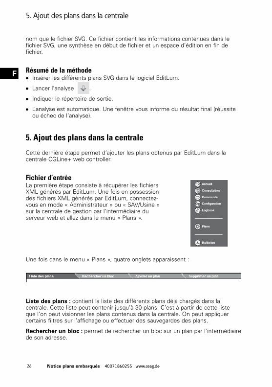
Fichier d’entréeLa première étape consiste à récupérer les fichiers XML générés par EditLum. Une fois en possession des fichiers XML générés par EditLum, connectez-vous en mode « Administrateur » ou « SAV/Usine » sur la centrale de gestion par l’intermédiaire du serveur web et allez dans le menu « Plans ».
Une fois dans le menu « Plans », quatre onglets apparaissent :
Liste des plans : contient la liste des différents plans déjà chargés dans la centrale. Cette liste peut contenir jusqu’à 30 plans. C’est à partir de cette liste que l’on peut visionner les plans contenus dans la centrale. On peut appliquer certains filtres sur l’affichage ou effectuer des sauvegardes des plans.
Rechercher un bloc : permet de rechercher un bloc sur un plan par l’intermédiaire de son adresse.
5. Ajout des plans dans la centrale
27Notice plans embarqués 40071860255 www.ceag.de
F
Ajouter un plan : permet d’ajouter un plan à la liste des plans contenus dans la centrale.
Supprimer un plan : permet de supprimer un plan de la liste des plans contenus dans la centrale.
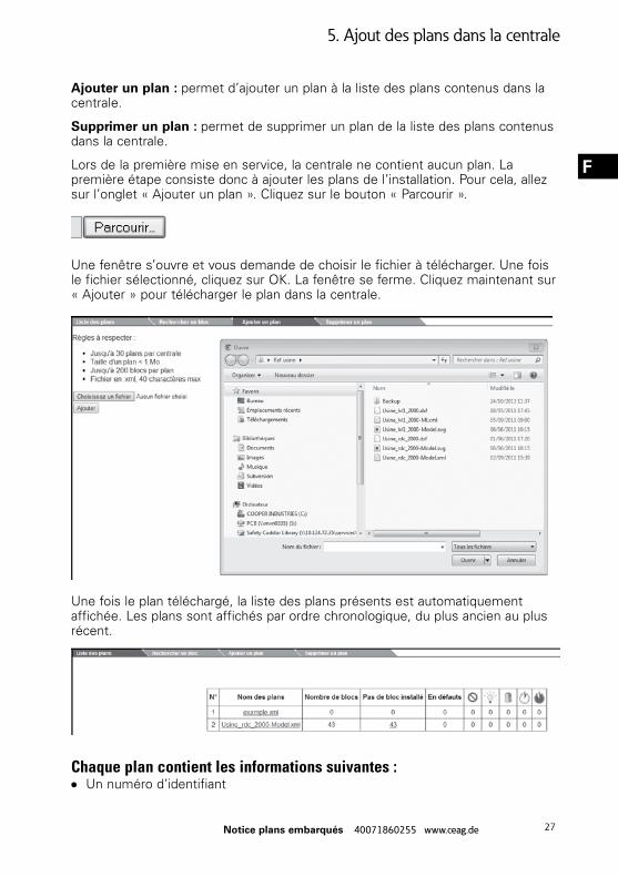
Lors de la première mise en service, la centrale ne contient aucun plan. La première étape consiste donc à ajouter les plans de l’installation. Pour cela, allez sur l’onglet « Ajouter un plan ». Cliquez sur le bouton « Parcourir ».
Une fenêtre s’ouvre et vous demande de choisir le fichier à télécharger. Une fois le fichier sélectionné, cliquez sur OK. La fenêtre se ferme. Cliquez maintenant sur « Ajouter » pour télécharger le plan dans la centrale.
Une fois le plan téléchargé, la liste des plans présents est automatiquement affichée. Les plans sont affichés par ordre chronologique, du plus ancien au plus récent.
Chaque plan contient les informations suivantes :OO Un numéro d’identifiant
5. Ajout des plans dans la centrale
28 Notice plans embarqués 40071860255 www.ceag.de
F
OO Un nom
OO Le nombre de blocs dessinés sur le plan
OO Le nombre de blocs en défaut
OO Des filtres d’affichages (bloc absent, défaut lampe, défaut batterie, défaut test fonctionnel et autonomie)
OO Date de la dernière sauvegarde et la possibilité d’effectuer une sauvegarde du plan sur un ordinateur
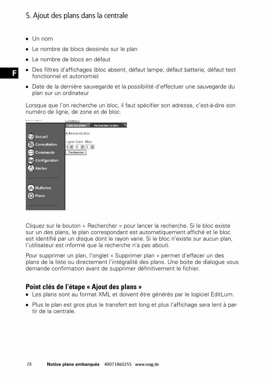
Lorsque que l’on recherche un bloc, il faut spécifier son adresse, c’est-à-dire son numéro de ligne, de zone et de bloc.
Cliquez sur le bouton « Rechercher » pour lancer la recherche. Si le bloc existe sur un des plans, le plan correspondant est automatiquement affiché et le bloc est identifié par un disque dont le rayon varie. Si le bloc n’existe sur aucun plan, l’utilisateur est informé que la recherche n’a pas abouti.
Pour supprimer un plan, l’onglet « Supprimer plan » permet d’effacer un des plans de la liste ou directement l’intégralité des plans. Une boite de dialogue vous demande confirmation avant de supprimer définitivement le fichier.
Point clés de l’étape « Ajout des plans »OO Les plans sont au format XML et doivent être générés par le logiciel EditLum.
OO Plus le plan est gros plus le transfert est long et plus l’affichage sera lent à par-tir de la centrale.
5. Ajout des plans dans la centrale
29Notice plans embarqués 40071860255 www.ceag.de
F
6. FAQ
1) Les points de statut des BAES ne s’affichent pas sur le plan.Vérifier que les numéros de centrale des blocs dans le schéma correspondent bien à celui de la centrale sur laquelle les plans sont consultés. Dans le cas contraire, les points ne s’affichent pas.
2) La recherche de bloc ne donne pas de résultat alors que le bloc est présent sur le plan.
Pour que la recherche donne un résultat, il faut que les conditions suivantes soient réunies :
OO Le bloc doit être présent sur le plan.
OO Le numéro de la centrale du bloc sur le plan doit correspondre à celui de la cen-trale sur laquelle la recherche est lancée.
OO Le bloc doit avoir été ajouté à la centrale via la fonction initialisation de celle-ci.
3) L’affichage des plans est lent.Pour avoir un affichage rapide, il est préférable d’avoir des plans faisant moins de 1 Mo en taille.
6. FAQ
30 Notice plans embarqués 40071860255 www.ceag.de
F
31Notice plans embarqués 40071860255 www.ceag.de
F
Eaton Industries Manufacturing GmbHElectrical Sector EMEARoute de la Longeraie 71110 Morges, SwitzerlandEaton.eu
All trademarks are property of their respective owners.
Cooper Sécurité SASPEER II - Rue Beethoven - BP1018463204 RIOM CEDEX – FRANCETél. 0825 826 212 (0,15 € TTC/min)www.cooperfrance.com
Eatons Ziel ist es, zuverlässige, effiziente und sichere Stromversorgung dann zu bieten, wenn sie am meisten benötigt wird. Die Experten von Eaton verfügen über ein umfassendes Fachwissen im Bereich Energiemanagement in verschiedensten Branchen und sorgen so für kundenspezifische, integrierte Lösungen, um anspruchsvollste Anforderungen der Kunden zu erfüllen.
Wir sind darauf fokussiert, stets die richtige Lösung für jede Anwendung zu finden. Dabei erwarten Entscheidungsträger mehr als lediglich innovative Produkte. Unternehmen wenden sich an Eaton, weil individuelle Unterstützung und der Erfolg unserer Kunden stets an erster Stelle stehen. Für mehr Informationen besuchen Sie www.eaton.com/electrical.
Eaton is dedicated to ensuring that reliable, efficient and safe power is available when it’s needed most. With unparalleled knowledge of electrical power management across industries, experts at Eaton deliver customized, integrated solutions to solve our customers’ most criticalchallenges.
Our focus is on delivering the right solution for the application. But, decision makers demand more than just innovative products. They turn to Eaton for an unwavering commitment to personal support that makes customer success a top priority. For more information, visit www.eaton.com/electrical.
L’objectif d’Eaton est de garantir la fiabilité, l’efficacité et la sécurité de vos installations électriques à tout moment. Forts d’un savoir-faire unique en matière de gestion de l’énergie électrique dans divers secteurs, nos experts fournissent des solutions intégrées et personnalisées pour résoudre les défis complexes des clients.
Pour Eaton, il est nécessaire de fournir la solution adaptée à l’application. Les décideurs exigent bien plus que des produits innovants : ils se tournent vers Eaton car nous nous engageons à les soutenir et à faire de leur réussite notre priorité absolue. Pour tout complément d’information, retrouvez-nous à l’adresse suivante : www.eaton.com/electrical