32
Chapter 5 – System Modeling 1 Chapter 5 System modeling
| Date post: | 16-Apr-2018 |
| Category: |
Documents |
| Upload: | nguyenhanh |
| View: | 219 times |
| Download: | 2 times |

Chapter 5 – System Modeling
1Chapter 5 System modeling

Event-driven modeling
Real-time systems are often event-driven, with minimal
data processing. For example, a landline phone
switching system responds to events such as ‘receiver
off hook’ by generating a dial tone.
Event-driven modeling shows how a system responds to
external and internal events.
It is based on the assumption that a system has a finite
number of states and that events (stimuli) may cause a
transition from one state to another.
Chapter 5 System modeling 2

State machine models
These model the behaviour of the system in response to
external and internal events.
They show the system’s responses to stimuli so are
often used for modelling real-time systems.
State machine models show system states as nodes and
events as arcs between these nodes. When an event
occurs, the system moves from one state to another.
Statecharts are an integral part of the UML and are used
to represent state machine models.
3Chapter 5 System modeling

State diagram of a microwave oven
4Chapter 5 System modeling

States and stimuli for the microwave oven (a)
State Description
Waiting The oven is waiting for input. The display shows the current time.
Half power The oven power is set to 300 watts. The display shows ‘Half power’.
Full power The oven power is set to 600 watts. The display shows ‘Full power’.
Set time The cooking time is set to the user’s input value. The display shows
the cooking time selected and is updated as the time is set.
Disabled Oven operation is disabled for safety. Interior oven light is on.
Display shows ‘Not ready’.
Enabled Oven operation is enabled. Interior oven light is off. Display shows
‘Ready to cook’.
Operation Oven in operation. Interior oven light is on. Display shows the timer
countdown. On completion of cooking, the buzzer is sounded for five
seconds. Oven light is on. Display shows ‘Cooking complete’ while
buzzer is sounding.
5Chapter 5 System modeling

States and stimuli for the microwave oven (b)
Stimulus Description
Half power The user has pressed the half-power button.
Full power The user has pressed the full-power button.
Timer The user has pressed one of the timer buttons.
Number The user has pressed a numeric key.
Door open The oven door switch is not closed.
Door closed The oven door switch is closed.
Start The user has pressed the Start button.
Cancel The user has pressed the Cancel button.
6Chapter 5 System modeling

Microwave oven operation
7Chapter 5 System modeling

Model-driven engineering
Model-driven engineering (MDE) is an approach to
software development where models rather than
programs are the principal outputs of the development
process.
The programs that execute on a hardware/software
platform are then generated automatically from the
models.
Proponents of MDE argue that this raises the level of
abstraction in software engineering so that engineers no
longer have to be concerned with programming
language details or the specifics of execution platforms.
Chapter 5 System modeling 8

Usage of model-driven engineering
Model-driven engineering is still at an early stage of
development, and it is unclear whether or not it will have
a significant effect on software engineering practice.
Pros
Allows systems to be considered at higher levels of abstraction
Generating code automatically means that it is cheaper to adapt
systems to new platforms.
Cons
Models for abstraction and not necessarily right for
implementation.
Savings from generating code may be outweighed by the costs
of developing translators for new platforms.
Chapter 5 System modeling 9

Model driven architecture
Model-driven architecture (MDA) was the precursor of
more general model-driven engineering
MDA is a model-focused approach to software design
and implementation that uses a subset of UML models to
describe a system.
Models at different levels of abstraction are created.
From a high-level, platform independent model, it is
possible, in principle, to generate a working program
without manual intervention.
Chapter 5 System modeling 10
Types of model
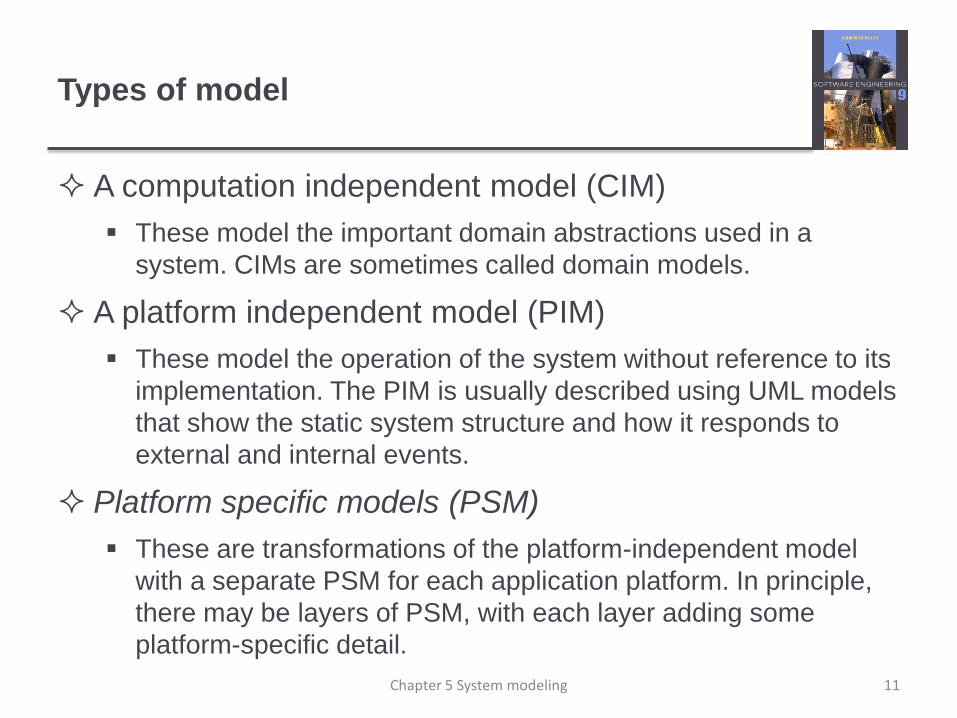
A computation independent model (CIM)
These model the important domain abstractions used in a
system. CIMs are sometimes called domain models.
A platform independent model (PIM)
These model the operation of the system without reference to its
implementation. The PIM is usually described using UML models
that show the static system structure and how it responds to
external and internal events.
Platform specific models (PSM)
These are transformations of the platform-independent model
with a separate PSM for each application platform. In principle,
there may be layers of PSM, with each layer adding some
platform-specific detail.
Chapter 5 System modeling 11

MDA transformations
12Chapter 5 System modeling

Multiple platform-specific models
13Chapter 5 System modeling

Agile methods and MDA
The developers of MDA claim that it is intended to
support an iterative approach to development and so can
be used within agile methods.
The notion of extensive up-front modeling contradicts the
fundamental ideas in the agile manifesto and I suspect
that few agile developers feel comfortable with model-
driven engineering.
If transformations can be completely automated and a
complete program generated from a PIM, then, in
principle, MDA could be used in an agile development
process as no separate coding would be required.
Chapter 5 System modeling 14
Executable UML
The fundamental notion behind model-driven
engineering is that completely automated transformation
of models to code should be possible.
This is possible using a subset of UML 2, called
Executable UML or xUML.
Chapter 5 System modeling 15

Features of executable UML
To create an executable subset of UML, the number of
model types has therefore been dramatically reduced to
these 3 key types:
Domain models that identify the principal concerns in a system.
They are defined using UML class diagrams and include objects,
attributes and associations.
Class models in which classes are defined, along with their
attributes and operations.
State models in which a state diagram is associated with each
class and is used to describe the life cycle of the class.
The dynamic behavior of the system may be specified
declaratively using the object constraint language (OCL),
or may be expressed using UML’s action language. Chapter 5 System modeling 16

Key points
Behavioral models are used to describe the dynamic behavior
of an executing system. This behavior can be modeled from
the perspective of the data processed by the system, or by
the events that stimulate responses from a system.
Activity diagrams may be used to model the processing of
data, where each activity represents one process step.
State diagrams are used to model a system’s behavior in
response to internal or external events.
Model-driven engineering is an approach to software
development in which a system is represented as a set of
models that can be automatically transformed to executable
code.
Chapter 5 System modeling 17

Chapter 6 – Architectural Design
Lecture 1
18Chapter 6 Architectural design

Topics covered
Architectural design decisions
Architectural views
Architectural patterns
Application architectures
19Chapter 6 Architectural design

Software architecture
The design process for identifying the sub-systems
making up a system and the framework for sub-system
control and communication is architectural design.
The output of this design process is a description of the
software architecture.
20Chapter 6 Architectural design

Architectural design
An early stage of the system design process.
Represents the link between specification and design
processes.
Often carried out in parallel with some specification
activities.
It involves identifying major system components and
their communications.
21Chapter 6 Architectural design

The architecture of a packing robot control
system
22Chapter 6 Architectural design

Architectural abstraction
Architecture in the small is concerned with the
architecture of individual programs. At this level, we are
concerned with the way that an individual program is
decomposed into components.
Architecture in the large is concerned with the
architecture of complex enterprise systems that include
other systems, programs, and program components.
These enterprise systems are distributed over different
computers, which may be owned and managed by
different companies.
23Chapter 6 Architectural design
Advantages of explicit architecture
Stakeholder communication
Architecture may be used as a focus of discussion by system stakeholders.
System analysis
Means that analysis of whether the system can meet its non-functional requirements is possible.
Large-scale reuse
The architecture may be reusable across a range of systems
Product-line architectures may be developed.
24Chapter 6 Architectural design

Architectural representations
Simple, informal block diagrams showing entities and
relationships are the most frequently used method for
documenting software architectures.
But these have been criticised because they lack
semantics, do not show the types of relationships
between entities nor the visible properties of entities in
the architecture.
Depends on the use of architectural models.The
requirements for model semantics depends on how the
models are used.
25Chapter 6 Architectural design

Box and line diagrams
Very abstract - they do not show the nature of
component relationships nor the externally visible
properties of the sub-systems.
However, useful for communication with stakeholders
and for project planning.
26Chapter 6 Architectural design

Use of architectural models
As a way of facilitating discussion about the system
design
A high-level architectural view of a system is useful for
communication with system stakeholders and project planning
because it is not cluttered with detail. Stakeholders can relate to
it and understand an abstract view of the system. They can then
discuss the system as a whole without being confused by detail.
As a way of documenting an architecture that has been
designed
The aim here is to produce a complete system model that shows
the different components in a system, their interfaces and their
connections.
Chapter 6 Architectural design 27

Architectural design decisions
Architectural design is a creative process so the process
differs depending on the type of system being
developed.
However, a number of common decisions span all
design processes and these decisions affect the non-
functional characteristics of the system.
28Chapter 6 Architectural design

Architectural design decisions
Is there a generic application architecture that can be
used?
How will the system be distributed?
What architectural styles are appropriate?
What approach will be used to structure the system?
How will the system be decomposed into modules?
What control strategy should be used?
How will the architectural design be evaluated?
How should the architecture be documented?
29Chapter 6 Architectural design

Architecture reuse
Systems in the same domain often have similar
architectures that reflect domain concepts.
Application product lines are built around a core
architecture with variants that satisfy particular customer
requirements.
The architecture of a system may be designed around
one of more architectural patterns or ‘styles’.
These capture the essence of an architecture and can be
instantiated in different ways.
Discussed later in this lecture.
30Chapter 6 Architectural design

Architecture and system characteristics
Performance
Localise critical operations and minimise communications. Use large rather than fine-grain components.
Security
Use a layered architecture with critical assets in the inner layers.
Safety
Localise safety-critical features in a small number of sub-systems.
Availability
Include redundant components and mechanisms for fault tolerance.
Maintainability
Use fine-grain, replaceable components.31Chapter 6 Architectural design
Architectural views
What views or perspectives are useful when designing
and documenting a system’s architecture?
What notations should be used for describing
architectural models?
Each architectural model only shows one view or
perspective of the system.
It might show how a system is decomposed into modules, how
the run-time processes interact or the different ways in which
system components are distributed across a network. For both
design and documentation, you usually need to present multiple
views of the software architecture.
32Chapter 6 Architectural design


