110
Co-resident Call Server and Signaling Server Fundamentals Avaya Communication Server 1000 Release 7.6 NN43001-509 Issue 04.01 March 2013
Co-resident Call Server and SignalingServer FundamentalsAvaya Communication Server 1000
Release 7.6NN43001-509
Issue 04.01March 2013
© 2013 Avaya Inc.
All Rights Reserved.
Notice
While reasonable efforts have been made to ensure that theinformation in this document is complete and accurate at the time ofprinting, Avaya assumes no liability for any errors. Avaya reserves theright to make changes and corrections to the information in thisdocument without the obligation to notify any person or organization ofsuch changes.
Documentation disclaimer
“Documentation” means information published by Avaya in varyingmediums which may include product information, operating instructionsand performance specifications that Avaya generally makes availableto users of its products. Documentation does not include marketingmaterials. Avaya shall not be responsible for any modifications,additions, or deletions to the original published version ofdocumentation unless such modifications, additions, or deletions wereperformed by Avaya. End User agrees to indemnify and hold harmlessAvaya, Avaya's agents, servants and employees against all claims,lawsuits, demands and judgments arising out of, or in connection with,subsequent modifications, additions or deletions to this documentation,to the extent made by End User.
Link disclaimer
Avaya is not responsible for the contents or reliability of any linkedwebsites referenced within this site or documentation provided byAvaya. Avaya is not responsible for the accuracy of any information,statement or content provided on these sites and does not necessarilyendorse the products, services, or information described or offeredwithin them. Avaya does not guarantee that these links will work all thetime and has no control over the availability of the linked pages.
Warranty
Avaya provides a limited warranty on its hardware and Software(“Product(s)”). Refer to your sales agreement to establish the terms ofthe limited warranty. In addition, Avaya’s standard warranty language,as well as information regarding support for this Product while underwarranty is available to Avaya customers and other parties through theAvaya Support website: http://support.avaya.com. Please note that ifyou acquired the Product(s) from an authorized Avaya reseller outsideof the United States and Canada, the warranty is provided to you bysaid Avaya reseller and not by Avaya. “Software” means computerprograms in object code, provided by Avaya or an Avaya ChannelPartner, whether as stand-alone products or pre-installed on hardwareproducts, and any upgrades, updates, bug fixes, or modified versions.
Licenses
THE SOFTWARE LICENSE TERMS AVAILABLE ON THE AVAYAWEBSITE, HTTP://SUPPORT.AVAYA.COM/LICENSEINFO AREAPPLICABLE TO ANYONE WHO DOWNLOADS, USES AND/ORINSTALLS AVAYA SOFTWARE, PURCHASED FROM AVAYA INC.,ANY AVAYA AFFILIATE, OR AN AUTHORIZED AVAYA RESELLER(AS APPLICABLE) UNDER A COMMERCIAL AGREEMENT WITHAVAYA OR AN AUTHORIZED AVAYA RESELLER. UNLESSOTHERWISE AGREED TO BY AVAYA IN WRITING, AVAYA DOESNOT EXTEND THIS LICENSE IF THE SOFTWARE WAS OBTAINEDFROM ANYONE OTHER THAN AVAYA, AN AVAYA AFFILIATE OR ANAVAYA AUTHORIZED RESELLER; AVAYA RESERVES THE RIGHTTO TAKE LEGAL ACTION AGAINST YOU AND ANYONE ELSEUSING OR SELLING THE SOFTWARE WITHOUT A LICENSE. BYINSTALLING, DOWNLOADING OR USING THE SOFTWARE, ORAUTHORIZING OTHERS TO DO SO, YOU, ON BEHALF OFYOURSELF AND THE ENTITY FOR WHOM YOU ARE INSTALLING,DOWNLOADING OR USING THE SOFTWARE (HEREINAFTERREFERRED TO INTERCHANGEABLY AS “YOU” AND “END USER”),AGREE TO THESE TERMS AND CONDITIONS AND CREATE ABINDING CONTRACT BETWEEN YOU AND AVAYA INC. OR THEAPPLICABLE AVAYA AFFILIATE (“AVAYA”).
Heritage Nortel Software
“Heritage Nortel Software” means the software that was acquired byAvaya as part of its purchase of the Nortel Enterprise SolutionsBusiness in December 2009. The Heritage Nortel Software currentlyavailable for license from Avaya is the software contained within the listof Heritage Nortel Products located at http://support.avaya.com/LicenseInfo under the link “Heritage Nortel Products”. For HeritageNortel Software, Avaya grants Customer a license to use HeritageNortel Software provided hereunder solely to the extent of theauthorized activation or authorized usage level, solely for the purposespecified in the Documentation, and solely as embedded in, forexecution on, or (in the event the applicable Documentation permitsinstallation on non-Avaya equipment) for communication with Avayaequipment. Charges for Heritage Nortel Software may be based onextent of activation or use authorized as specified in an order or invoice.
Copyright
Except where expressly stated otherwise, no use should be made ofmaterials on this site, the Documentation, Software, or hardwareprovided by Avaya. All content on this site, the documentation and theProduct provided by Avaya including the selection, arrangement anddesign of the content is owned either by Avaya or its licensors and isprotected by copyright and other intellectual property laws including thesui generis rights relating to the protection of databases. You may notmodify, copy, reproduce, republish, upload, post, transmit or distributein any way any content, in whole or in part, including any code andsoftware unless expressly authorized by Avaya. Unauthorizedreproduction, transmission, dissemination, storage, and or use withoutthe express written consent of Avaya can be a criminal, as well as acivil offense under the applicable law.
Third Party Components
“Third Party Components” mean certain software programs or portionsthereof included in the Software that may contain software (includingopen source software) distributed under third party agreements (“ThirdParty Components”), which contain terms regarding the rights to usecertain portions of the Software (“Third Party Terms”). Informationregarding distributed Linux OS source code (for those Products thathave distributed Linux OS source code) and identifying the copyrightholders of the Third Party Components and the Third Party Terms thatapply is available in the Documentation or on Avaya’s website at: http://support.avaya.com/Copyright. You agree to the Third Party Terms forany such Third Party Components.
Note to Service Provider
The Product may use Third Party Components that have Third PartyTerms that do not allow hosting and may need to be independentlylicensed for such purpose.
Preventing Toll Fraud
“Toll Fraud” is the unauthorized use of your telecommunications systemby an unauthorized party (for example, a person who is not a corporateemployee, agent, subcontractor, or is not working on your company'sbehalf). Be aware that there can be a risk of Toll Fraud associated withyour system and that, if Toll Fraud occurs, it can result in substantialadditional charges for your telecommunications services.
Avaya Toll Fraud intervention
If you suspect that you are being victimized by Toll Fraud and you needtechnical assistance or support, call Technical Service Center TollFraud Intervention Hotline at +1-800-643-2353 for the United Statesand Canada. For additional support telephone numbers, see the AvayaSupport website: http://support.avaya.com. Suspected securityvulnerabilities with Avaya products should be reported to Avaya bysending mail to: [email protected].
Trademarks
The trademarks, logos and service marks (“Marks”) displayed in thissite, the Documentation and Product(s) provided by Avaya are theregistered or unregistered Marks of Avaya, its affiliates, or other third
2 Co-resident Call Server and Signaling Server Fundamentals March 2013Comments? [email protected]
parties. Users are not permitted to use such Marks without prior writtenconsent from Avaya or such third party which may own the Mark.Nothing contained in this site, the Documentation and Product(s)should be construed as granting, by implication, estoppel, or otherwise,any license or right in and to the Marks without the express writtenpermission of Avaya or the applicable third party.
Avaya is a registered trademark of Avaya Inc.
All non-Avaya trademarks are the property of their respective owners,and “Linux” is a registered trademark of Linus Torvalds.
Downloading Documentation
For the most current versions of Documentation, see the AvayaSupport website: http://support.avaya.com.
Contact Avaya Support
See the Avaya Support website: http://support.avaya.com for productnotices and articles, or to report a problem with your Avaya product.For a list of support telephone numbers and contact addresses, go tothe Avaya Support website: http://support.avaya.com, scroll to thebottom of the page, and select Contact Avaya Support.
Co-resident Call Server and Signaling Server Fundamentals March 2013 3

4 Co-resident Call Server and Signaling Server Fundamentals March 2013Comments? [email protected]
Contents
Chapter 1: New in this release........................................................................................... 9Navigation................................................................................................................................................. 9Features.................................................................................................................................................... 9Other......................................................................................................................................................... 9
Revision History............................................................................................................................... 9Chapter 2: Customer service............................................................................................. 11
Navigation................................................................................................................................................. 11Getting technical documentation............................................................................................................... 11Getting product training............................................................................................................................. 11Getting help from a distributor or reseller.................................................................................................. 11Getting technical support from the Avaya Web site.................................................................................. 12
Chapter 3: Introduction...................................................................................................... 13Subject...................................................................................................................................................... 13Legacy products and releases.................................................................................................................. 13Applicable systems................................................................................................................................... 13Intended audience.................................................................................................................................... 13Co-res CS and SS task flow...................................................................................................................... 14Conventions.............................................................................................................................................. 15Technical publications............................................................................................................................... 16
Chapter 4: Overview........................................................................................................... 17Introduction............................................................................................................................................... 17Supported configurations.......................................................................................................................... 17
Overview.......................................................................................................................................... 17Hardware platforms.......................................................................................................................... 18Co-res CS and SS based CS 1000E system................................................................................... 19Optional second Signaling Server.................................................................................................... 20Co-res CS and SS based MG 1000B............................................................................................... 20CS 1000E TDM................................................................................................................................ 21
High Availability (HA) support................................................................................................................... 22Co-resident CS and SS upgrade paths..................................................................................................... 22Hardware................................................................................................................................................... 22
CP PM upgrade kit........................................................................................................................... 23CP PM Media Storage...................................................................................................................... 23CP MG, CP DC, and COTS2 media storage.................................................................................... 23
Software applications................................................................................................................................ 24Element Manager...................................................................................................................................... 25
Chapter 5: Planning and engineering............................................................................... 27Introduction............................................................................................................................................... 27System parameter considerations............................................................................................................. 27Hardware requirements............................................................................................................................. 27Security dongle......................................................................................................................................... 28Ethernet port connections......................................................................................................................... 29
Server and MGC connections.......................................................................................................... 29Routing Table configuration...................................................................................................................... 31
Co-resident Call Server and Signaling Server Fundamentals March 2013 5
Co-res CS and SS feature package requirements.................................................................................... 32Co-res CS and SS deployment configurations......................................................................................... 33Signaling Server deployment limitations................................................................................................... 34System capacity........................................................................................................................................ 34Future growth considerations.................................................................................................................... 36IP address considerations......................................................................................................................... 37
New systems.................................................................................................................................... 37Upgrades.......................................................................................................................................... 37
Chapter 6: Installation and commissioning...................................................................... 39Introduction............................................................................................................................................... 39Pre-installation checklist............................................................................................................................ 39
Determining CP PM BIOS Method 1................................................................................................ 40Determining CP PM BIOS Method 2................................................................................................ 40Upgrading the CP PM BIOS............................................................................................................. 41
CS 1000 Linux Base................................................................................................................................. 44Co-res CS and SS application installation................................................................................................ 45Call Server keycode upload and validation, language and database selection........................................ 45
Chapter 7: Upgrades........................................................................................................... 47Introduction............................................................................................................................................... 47Supported upgrade paths......................................................................................................................... 47Hardware................................................................................................................................................... 47CP PM hard drive and memory upgrades................................................................................................. 48Co-resident CS and SS application software upgrade (7.0 to 7.6)........................................................... 48Backing up the CS 1000E Call Server database...................................................................................... 49Installing or upgrading the Co-res CS and SS using the CS 1000E Call Server database...................... 49Installing or upgrading the Co-res CS and SS without using the CS 1000E Call Server database.......... 49Call Server installation support................................................................................................................. 50
Chapter 8: Migration from an SSC-based small system................................................. 53Supported migration paths........................................................................................................................ 53
Small System Call Server backup to an external drive.................................................................... 53Choosing the cabinet or chassis and slot locations.................................................................................. 57
Cabinet............................................................................................................................................. 58Chassis............................................................................................................................................. 59Avaya CS 1000S.............................................................................................................................. 62
Hardware Upgrade Task Overview........................................................................................................... 63Card installation................................................................................................................................ 64Cabling the cards............................................................................................................................. 69
Linux base and applications installation.................................................................................................... 71Chapter 9: Patching............................................................................................................ 73
Patching the Co-res CS and SS............................................................................................................... 73Patching Call Server binary patches......................................................................................................... 73Element Manager patching....................................................................................................................... 74Linux patching........................................................................................................................................... 74Call Server deplist..................................................................................................................................... 75
Chapter 10: Feature operation........................................................................................... 77Call Server................................................................................................................................................ 77
Chapter 11: Configuration management........................................................................... 79
6 Co-resident Call Server and Signaling Server Fundamentals March 2013
OAM User Interface.................................................................................................................................. 79Access to the Co-res CS and SS..................................................................................................... 80
IP Management for Co-res CS and SS..................................................................................................... 83NTP and TOD configuration............................................................................................................. 85
Security configuration................................................................................................................................ 100UCM configuration............................................................................................................................ 100Centralized authentication................................................................................................................ 101CS 1000 Access Restrictions........................................................................................................... 101cspdt and cslogin.............................................................................................................................. 102Shell and transfer commands........................................................................................................... 103SSH Commands............................................................................................................................... 105
IP Sec........................................................................................................................................................ 106Chapter 12: Maintenance.................................................................................................... 107
Power up and power down procedures.................................................................................................... 107Diagnostic logs.......................................................................................................................................... 107
Call Server RPT log viewer.............................................................................................................. 107Call Server csconsole log................................................................................................................. 108
Chapter 13: System messages.......................................................................................... 109Co-res CS and SS system messages....................................................................................................... 109
Co-resident Call Server and Signaling Server Fundamentals March 2013 7

8 Co-resident Call Server and Signaling Server Fundamentals March 2013
Chapter 1: New in this release
The following sections detail what is new in this document for Avaya Communication Server 1000 (AvayaCS 1000) Release 7.6.
Navigation• Features on page 9
• Other on page 9
FeaturesThere are no updates to the feature descriptions in this document.
Other
Revision History
March 2013 Standard 04.01. This document is up-issued to support the Co-resident Call Server and Signaling Server for AvayaCommunication Server 1000 Release 7.6.
August 2011 Standard 03.03. This document is up-issued to support the Co-resident Call Server and Signaling Server for AvayaCommunication Server 1000 Release 7.5.
March 2011 Standard 03.02. This document is up-issued to support the Co-resident Call Server and Signaling Server for AvayaCommunication Server 1000 Release 7.5.
Co-resident Call Server and Signaling Server Fundamentals March 2013 9
November 2010 Standard 03.01. This document is up-issued to support the Co-resident Call Server and Signaling Server for AvayaCommunication Server 1000 Release 7.5.
May 2011 Standard 02.05. This document is up-issued to provideinformation about supported memory sticks.
July 2010 Standard 02.04. This document is up-issued to updateplanning and engineering content.
July 2010 Standard 02.03. This document is up-issued to includerecommended USB memory stick support.
June 2010 Standard 02.02. This document is up-issued to include CP PMversion 2 content.
June 2010 Standard 02.01. This document is issued to support the Co-resident Call Server and Signaling Server for AvayaCommunication Server 1000 Release 7.0.
October 2009 Standard 01.06. This is a new document created to support CPPM Co-res CS and SS for Communication Server 1000Release 6.0
September 2009 Standard 01.05. This is a new document created to support CPPM Co-res CS and SS for Communication Server 1000Release 6.0
July 2009 Standard 01.04. This is a new document created to support CPPM Co-res CS and SS for Communication Server 1000Release 6.0.
June 2009 Standard 01.03. This is a new document created to support CPPM Co-res CS and SS for Communication Server 1000Release 6.0.
May 2009 Standard 01.02. This is a new document created to support CPPM Co-res CS and SS for Communication Server 1000Release 6.0.
May 2009 Standard 01.01. This is a new document created to support CPPM Co-res CS and SS for Communication Server 1000Release 6.0.
New in this release
10 Co-resident Call Server and Signaling Server Fundamentals March 2013Comments? [email protected]
Chapter 2: Customer service
Visit the Avaya Web site to access the complete range of services and support that Avaya provides. Goto www.avaya.com or go to one of the pages listed in the following sections.
Navigation• Getting technical documentation on page 11
• Getting product training on page 11
• Getting help from a distributor or reseller on page 11
• Getting technical support from the Avaya Web site on page 12
Getting technical documentationTo download and print selected technical publications and release notes directly from theInternet, go to www.avaya.com/support.
Getting product trainingOngoing product training is available. For more information or to register, go to www.avaya.com/support. From this Web site, locate the Training link on the left-handnavigation pane.
Getting help from a distributor or resellerIf you purchased a service contract for your Avaya product from a distributor or authorizedreseller, contact the technical support staff for that distributor or reseller for assistance.
Co-resident Call Server and Signaling Server Fundamentals March 2013 11
Getting technical support from the Avaya Web siteThe easiest and most effective way to get technical support for Avaya products is from theAvaya Technical Support Web site at www.avaya.com/support.
Customer service
12 Co-resident Call Server and Signaling Server Fundamentals March 2013Comments? [email protected]
Chapter 3: Introduction
This is a global document. Contact your system supplier or your Avaya representative to verify that supportexists in your area for the hardware and software described in this document.
SubjectThis document provides information about Co-resident Call Server and Signaling Server (Co-res CS and SS) for Avaya Communication Server 1000 (Avaya CS 1000).
Legacy products and releasesThis document contains information about systems, components, and features that arecompatible with Avaya Communication Server 1000. For more information about legacyproducts and releases, go to http://support.avaya.com/.
Applicable systemsThis document applies to the following systems:
• Communication Server 1000E (CS 1000E)
• Avaya CS 1000 Media Gateway 1000 B (Avaya MG 1000B)
• Survivable Media Gateway (SMG)
Intended audienceThis document is intended for individuals who install, configure and maintain Co-res CS andSS in a CS 1000 environment.
Only qualified personnel are to install Co-res CS and SS. To use this document, you must havea working knowledge of CS 1000E, CS 1000M, and Meridian 1 equipment and operation.Contact Avaya for information on installation courses.
Co-resident Call Server and Signaling Server Fundamentals March 2013 13
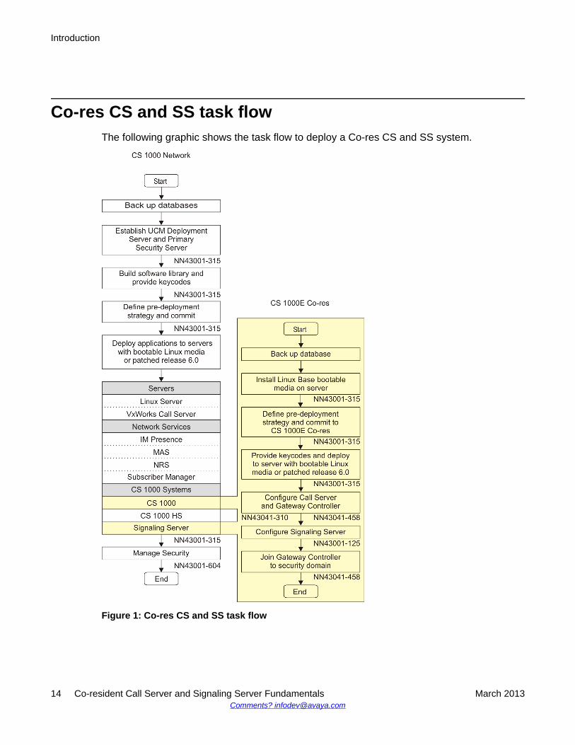
Co-res CS and SS task flowThe following graphic shows the task flow to deploy a Co-res CS and SS system.
Figure 1: Co-res CS and SS task flow
Introduction
14 Co-resident Call Server and Signaling Server Fundamentals March 2013Comments? [email protected]
ConventionsIn this document, CS 1000E is referred to generically as system.
In this document, the following Chassis or Cabinets are referred to generically as MediaGateway:
• Option 11C Mini Chassis (NTDK91) and Chassis Expander (NTDK92)
• Option 11C Cabinet (NTAK11)
• Avaya CS 1000 Media Gateway 1000E (Avaya MG 1000E) Chassis (NTDU14) andExpansion Chassis (NTDU15)
• Media Gateway 1010 (MG 1010) (NTC310)
In this document, the following hardware is referred to as Gateway Controller:
• Media Gateway Controller (MGC) card (NTDW60 and NTDW98)
• Common Processor Media Gateway (CP MG) card (NTDW56 and NTDW59)
In this document, the following hardware is referred to generically as Server:
• Common Processor Pentium Mobile (CP PM) card
• Common Processor Media Gateway (CP MG) card
• Common Processor Dual Core (CP DC) card
• Commercial off-the-shelf (COTS) servers
- IBM x306m server (COTS1)
- HP DL320 G4 server (COTS1)
- IBM x3350 server (COTS2)
- Dell R300 server (COTS2)
In this document, the generic term COTS refers to all COTS servers. The term COTS1 orCOTS2 refers to the specific servers in the preceding list.
Co-res CS and SS is not supported on COTS1 servers. You can deploy a COTS1 server as astand-alone Signaling Server.
The following table shows Communication Server 1000 Release 7.6 supported roles forhardware platforms.
Conventions
Co-resident Call Server and Signaling Server Fundamentals March 2013 15
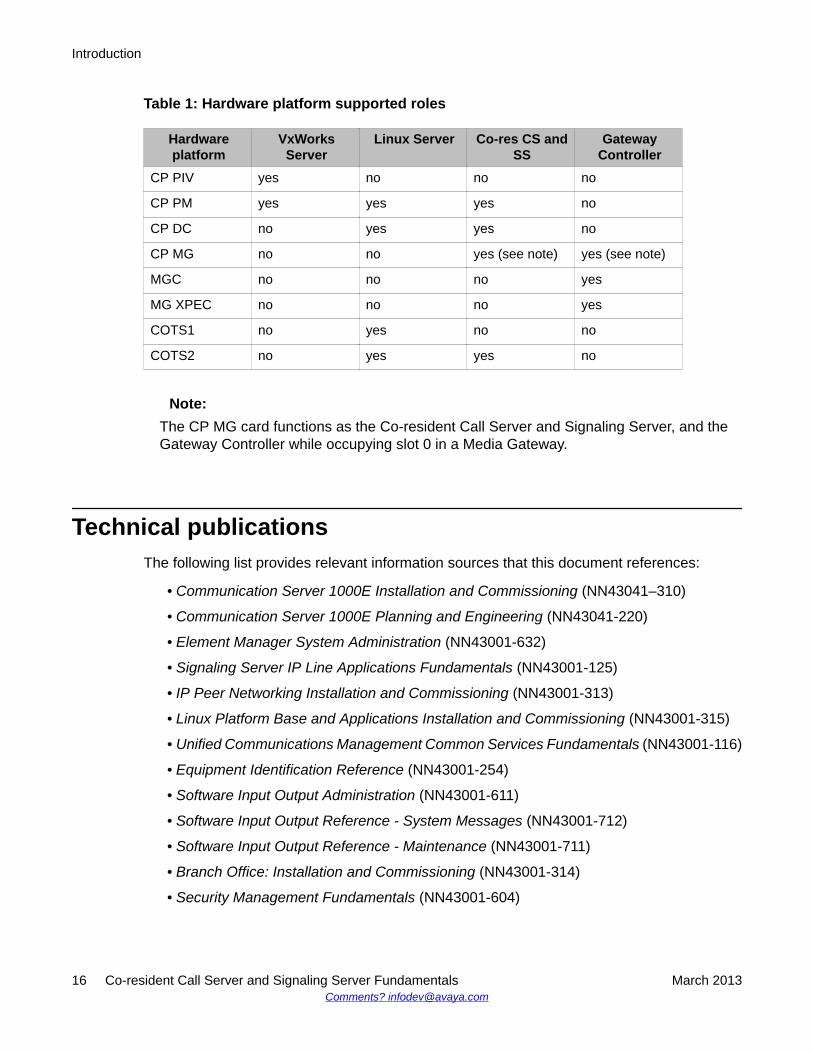
Table 1: Hardware platform supported roles
Hardwareplatform
VxWorksServer
Linux Server Co-res CS andSS
GatewayController
CP PIV yes no no no
CP PM yes yes yes no
CP DC no yes yes no
CP MG no no yes (see note) yes (see note)
MGC no no no yes
MG XPEC no no no yes
COTS1 no yes no no
COTS2 no yes yes no
Note:The CP MG card functions as the Co-resident Call Server and Signaling Server, and theGateway Controller while occupying slot 0 in a Media Gateway.
Technical publicationsThe following list provides relevant information sources that this document references:
• Communication Server 1000E Installation and Commissioning (NN43041–310)
• Communication Server 1000E Planning and Engineering (NN43041-220)
• Element Manager System Administration (NN43001-632)
• Signaling Server IP Line Applications Fundamentals (NN43001-125)
• IP Peer Networking Installation and Commissioning (NN43001-313)
• Linux Platform Base and Applications Installation and Commissioning (NN43001-315)
• Unified Communications Management Common Services Fundamentals (NN43001-116)
• Equipment Identification Reference (NN43001-254)
• Software Input Output Administration (NN43001-611)
• Software Input Output Reference - System Messages (NN43001-712)
• Software Input Output Reference - Maintenance (NN43001-711)
• Branch Office: Installation and Commissioning (NN43001-314)
• Security Management Fundamentals (NN43001-604)
Introduction
16 Co-resident Call Server and Signaling Server Fundamentals March 2013Comments? [email protected]
Chapter 4: Overview
IntroductionAn Avaya Communication Server 1000 (CS 1000) system consists of two major functionalcomponents: a Call Server and a Signaling Server. These two components have historicallyrun on separate Intel Pentium processor-based hardware platforms operating under theVxWorks Operating System.
The CS 1000 Co-resident Call Server and Signaling Server (Co-res CS and SS) runs the CallServer software, the Signaling Server software, and System Management software on onehardware platform running the CS 1000 Linux Base Operating System. Co-res CS and SSsupports various hardware platforms, see Table 1: Hardware platform supported roles onpage 16.
The key objective of co-residency is to provide a cost-effective solution for CS 1000 systeminstallations that do not require high user capacity or the need for a redundant Call Server.
Supported configurations
OverviewYou can deploy the Co-res CS and SS in the following configurations:
• CS 1000E
• Media Gateway 1000 B ( MG 1000B)
• Survivable Media Gateway (SMG)
• Survivable SIP Media Gateway (Surviviable SIP MG)
• CS 1000E TDM
You can deploy a Co-res CS and SS as a Main Office, Branch Office, or Survivable SIP MG.
Co-resident Call Server and Signaling Server Fundamentals March 2013 17
Note:For details on CS 1000E capacity limitations, see Planning and engineering on page 27
Hardware platformsCS 1000 Co-resident Call Server and Signaling Server (Co-res CS and SS), is capable ofrunning the Call Server software, Signaling Server software, and System Managementsoftware on a hardware platform running the Linux Base Operating System.
Various hardware platforms support the Co-res CS and SS configuration. For information aboutthe supported hardware roles, see Table 1: Hardware platform supported roles on page 16.
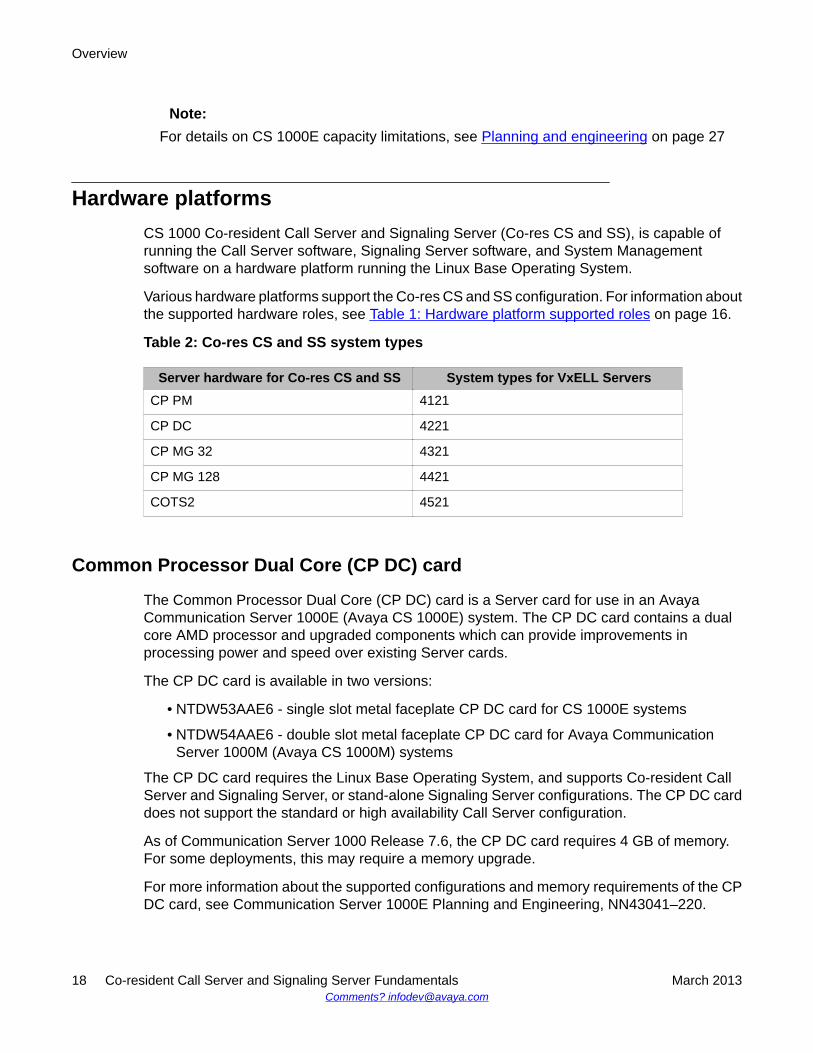
Table 2: Co-res CS and SS system types
Server hardware for Co-res CS and SS System types for VxELL ServersCP PM 4121
CP DC 4221
CP MG 32 4321
CP MG 128 4421
COTS2 4521
Common Processor Dual Core (CP DC) card
The Common Processor Dual Core (CP DC) card is a Server card for use in an AvayaCommunication Server 1000E (Avaya CS 1000E) system. The CP DC card contains a dualcore AMD processor and upgraded components which can provide improvements inprocessing power and speed over existing Server cards.
The CP DC card is available in two versions:
• NTDW53AAE6 - single slot metal faceplate CP DC card for CS 1000E systems
• NTDW54AAE6 - double slot metal faceplate CP DC card for Avaya CommunicationServer 1000M (Avaya CS 1000M) systems
The CP DC card requires the Linux Base Operating System, and supports Co-resident CallServer and Signaling Server, or stand-alone Signaling Server configurations. The CP DC carddoes not support the standard or high availability Call Server configuration.
As of Communication Server 1000 Release 7.6, the CP DC card requires 4 GB of memory.For some deployments, this may require a memory upgrade.
For more information about the supported configurations and memory requirements of the CPDC card, see Communication Server 1000E Planning and Engineering, NN43041–220.
Overview
18 Co-resident Call Server and Signaling Server Fundamentals March 2013Comments? [email protected]
Common Processor Media Gateway (CP MG) card
The hardware for the Common Processor Media Gateway (CP MG) card consists of integratinga Common Processor, a Gateway Controller, and non-removable Digital Signal Processor(DSP) resources into a single card for use in a CS 1000E system.
The CP MG card is available in two versions:
• NTDW56BAE6 - CP MG card with 32 DSP ports
• NTDW59BAE6 - CP MG card with 128 DSP ports
The CP MG card provides improvements in port density and cost reductions by functioning asa Call Server or Application Server and a Gateway Controller with DSP resources whileoccupying slot 0 in a Media Gateway. The CP MG card requires the Linux Base OperatingSystem. The CP MG 128 supports the Co-resident Call Server and Signaling Server, and CS1000E TDM configurations. The CP MG 32 supports the SIP Survivable Media Gateway(SSMG), and Branch Office configurations. The CP MG card does not support the standard orhigh availability Call Server configuration.
As of Communication Server 1000 Release 7.6, the CP MG card requires 4 GB of memory.For some deployments, this requires a memory upgrade.
For more information about the supported configurations and memory requirements of the CPMG card, see Communication Server 1000E Planning and Engineering, NN43041–220.
128-port DSP daughterboard
The 128-port Digital Signal Processor (DSP) daughterboard (DB-128) for the Media GatewayController (MGC) card populated with one NTDW78 DB-128 can provide 128 DSP ports.
The CS 1000E Peripheral Rate Interface (PRI) Media Gateway (PRI Gateway) can support aMGC card populated with two DB-128 for a maximum of 256 DSP ports. The Extended MediaGateway PRI (MGP) package 418 is required to support MGC cards populated with two DB-96or two DB-128.
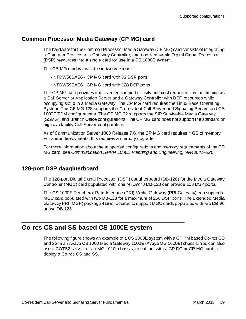
Co-res CS and SS based CS 1000E systemThe following figure shows an example of a CS 1000E system with a CP PM based Co-res CSand SS in an Avaya CS 1000 Media Gateway 1000E (Avaya MG 1000E) chassis. You can alsouse a COTS2 server, or an MG 1010, chassis, or cabinet with a CP DC or CP MG card todeploy a Co-res CS and SS.
Supported configurations
Co-resident Call Server and Signaling Server Fundamentals March 2013 19
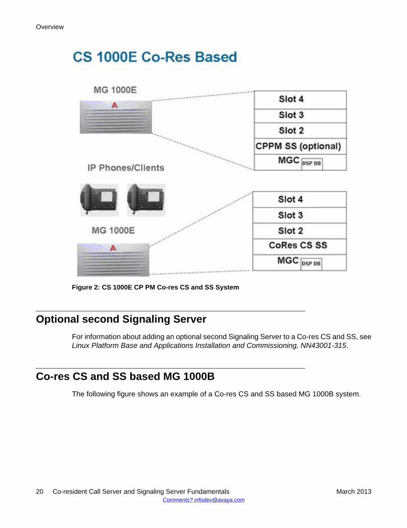
Figure 2: CS 1000E CP PM Co-res CS and SS System
Optional second Signaling ServerFor information about adding an optional second Signaling Server to a Co-res CS and SS, seeLinux Platform Base and Applications Installation and Commissioning, NN43001-315.
Co-res CS and SS based MG 1000BThe following figure shows an example of a Co-res CS and SS based MG 1000B system.
Overview
20 Co-resident Call Server and Signaling Server Fundamentals March 2013Comments? [email protected]
Figure 3: MG 1000B CP PM Co-res CS and SS System
CS 1000E TDMThere is a TDM only version of the Co-res CS and SS on CP PM, CP DC, and CP MG 128platforms. The CS 1000E TDM system has the following capacity limitations:
• 720–800 combined TDM users (Traditional, CLASS, DECT users, including installed plusadd-on)
• a maximum of 5 Media Gateways
• a maximum of 16 PRI cards
• a maximum of 200 ACD Agents
• 0 IP Phones (no UniSTIM, no SipLine, no SipDect)
• 0 virtual trunks
Note:The CS 1000E TDM system does not support NRS. The CS 1000E TDM system does notsupport CP MG 32 or COTS platforms.
TDM user range of 720–800 is based on Cabinet or Chassis card slot limits.
Supported configurations
Co-resident Call Server and Signaling Server Fundamentals March 2013 21
High Availability (HA) supportThe Co-res CS and SS does not support an HA configuration (dual core with either Active orInactive role). For systems that require HA configuration, you must deploy a VxWorks-basedCS 1000 system.
Co-resident CS and SS upgrade pathsThe following upgrade paths are supported for CS 1000 systems.
• CS 1000 Release 7.5 or earlier Communication Server 1000E Call Server with StandardAvailability (SA) to a CS 1000 Release 7.6 Co-resident Call Server and Signaling Server
• CS 1000 Release 7.5 or earlier CS 1000E Signaling Server to CS 1000 Release 7.6 Co-resident Call Server and Signaling Server
• Meridian 1 Option 11C, CS 1000M, or CS 1000S Call Server to Communication Server1000 Release 7.6 Co-resident Call Server and Signaling Server
• Meridian 1 Option 11C Call Server to CS 1000 Release 7.6 CS 1000E TDM
Note:Minimum CS 1000 Release for Small System migration to Co-resident CS and SS isRelease 23.10.
Note:If you upgrade from a non-CP PM based CS 1000E Server, you must replace your oldServer hardware with a supported Server and upgrade the software.
HardwareCo-resident Call Server and Signaling Server is supported on CP PM cards, CP MG cards, CPDC cards, and COTS2 servers running the CS 1000 Linux Base Operating System.
The Co-res CS and SS can run on the CP PM hardware platform introduced in CS 1000Release 5.0, however the software changes from VxWorks to Linux, and a CP PM Linuxupgrade kit is required. The CP PM card requires BIOS version 18 or later, 2 GB memory, anda 40 GB hard drive to support the Co-res CS and SS configuration. All other platforms require4 GB memory.
Overview
22 Co-resident Call Server and Signaling Server Fundamentals March 2013Comments? [email protected]
Note:You must upgrade CP DC or CP MG hardware from 2 GB of memory to 4 GB of memorywith a Linux Upgrade Kit.
For more information about the hardware platforms, see Circuit Card Reference,NN43001-311.
CP PM upgrade kitThe CP PM Server Linux Upgrade kit can include the following items:
• 2 GB Compact Flash (CF) with Linux software
• 1 GB DDR SO-DIMM memory
• 40 GB Hard Drive kit , Linux OS preloaded (optional, provisioned if required)
CP PM Media StorageFor CP PM cards configured with an internal hard drive Fixed Media Drive (FMD), you mustensure switch S5 on the CP PM card is in position 2. Position 2 configures the CP PM card toboot from the hard drive FMD. Switch S5 in position 1 configures the CP PM card to boot fromthe internal Compact Flash (CF) FMD. The hard drive FMD is required for Linux deployments.The CF card FMD is required for VxWorks deployments.
The CP PM card supports two types of Removable Media Drives (RMD)
• CF card, supports the installation of CS 1000 Linux Base and Linux applications
• USB memory stick device, supports the installation of Linux applications (cannot use toinstall CS 1000 Linux Base)
Note:CF cards and USB memory sticks are supported for database back up and restore.
For CS 1000 Linux Base and Linux application software installations, the minimum sizesupported for the RMD is 1 GB. For more information about supported media for Co-res CSand SS installations, see Linux Platform Base and Applications Installation andCommissioning, NN43001-315.
CP MG, CP DC, and COTS2 media storageThe CP MG card, CP DC card, and COTS2 servers require an internal hard drive Fixed MediaDrive (FMD). The FMD contains the Linux Base Operating System. The CP MG and CP DC
Hardware
Co-resident Call Server and Signaling Server Fundamentals March 2013 23
card use a 160 GB SATA FMD. The COTS2 servers contain different sizes of SATA FMD basedon your purchase configuration.
The CP MG, CP DC, and COTS2 support USB 2.0 storage devices as Removable MediaDrives (RMD). A bootable USB 2.0 storage device can be used to install or patch the LinuxBase Operating System. The CP MG, CP DC and COTS2 hardware platforms do not supportCF cards as RMD.
Note:The N0220961 USB memory stick is supported for Communication Server 1000 Release7.0. Not all USB memory sticks are supported.
For information about installing hard drives on circuit cards, see Circuit Card Reference,NN43001-311. For information about installing hard drives on COTS servers, see yourmanufacturers COTS server user manual.
Software applicationsThe Co-res CS and SS supports the following software applications:
• Linux Call Server
• Line Telephony Proxy Server (LTPS)
• Unicode Name Directory (UND)
• Signaling Server Gateway including H.323 Gateway and SIP Gateway
• SIP Line Gateway
• Failsafe SIP Proxy Service, Gatekeeper
• Personal Directory (PD)
• Network Routing Service (NRS)
- You can configure the NRS as Primary, however you can only configure NRS as aSecondary if the Primary is also running on a Co-res CS and SS.
- The CP PM based Co-res CS and SS does not support a Secondary or backup NRSto capacity higher than the Primary NRS due to the small disk size and low call rateson a CP PM based Co-res CS and SS.
• Element Manager
• Unified Communication Management Primary Security Server in limited deployment. Fordetailed UCM Primary Security Server procedures, see Linux Platform Base andApplications Installation and Commissioning, NN43001-315
Overview
24 Co-resident Call Server and Signaling Server Fundamentals March 2013Comments? [email protected]
Note:Co-resident Call Server and Signaling Servers with only 2 GB of memory (such as the CPPM card) do not support all Signaling Server applications and an NRS.
In addition to the application restrictions, there are also management restrictions. DeployingPrimary UCM, Deployment Manager, EM, NRSM and Subscriber Manager on a server withonly 2 GB of memory is not supported.
For recommended deployment options of a 2 GB CP PM Co-res CS and SS, see the Co-Resident Signaling Server (CS 1000E, CS 1000B) section of Communication Server 1000EPlanning and Engineering, NN43041-220.
Element ManagerThe Element Manager (EM) interface includes the configuration and enabling of SignalingServer application services such as UNIStim, LTPS, SIP Gateway, H.323 Gateway, and SIPLine.
For more information about EM, see Element Manager System Reference - Administration,NN43001-632.
Element Manager
Co-resident Call Server and Signaling Server Fundamentals March 2013 25

Overview
26 Co-resident Call Server and Signaling Server Fundamentals March 2013Comments? [email protected]
Chapter 5: Planning and engineering
IntroductionComplete all system planning and engineering activities before using this guide to install a Co-resident Call Server and Signaling Server (Co-res CS and SS).
System parameter considerationsThe Co-res CS and SS Call Server provides the same functionality as the existing VxWorks-based Call Server but with less capacity.
The Co-res CS and SS Signaling Server applications provide the same functionality as aSignaling Server that runs one or more Signaling Server applications but with lower capacity.
Engineering of Media Gateway card placement and DSPs is the same as for an AvayaCommunication Server 1000E system. For details, see Communication Server 1000EPlanning and Engineering, NN43041–220.
Hardware requirementsThe Co-res CS and SS can be deployed on various hardware platforms. For AvayaCommunication Server 1000 (Avaya CS 1000) Release 7.0, the Co-res CS and SS supportsthe following Servers:
• Common Processor Pentium Mobile (CP PM) card• Common Processor Media Gateway (CP MG) card• Common Processor Dual Core (CP DC) card• IBM x3350 and Dell R300 Commercial off-the-shelf (COTS) servers (COTS2)
The Server cards install in Media Gateway IPE slots, the COTS servers install in standard 19inch racks.
One Gateway Controller is required in each Media Gateway cabinet or chassis. The GatewayController can be an MGC card or a CP MG card.
Co-resident Call Server and Signaling Server Fundamentals March 2013 27
Note:The CP MG card functions as a Gateway Controller and a Co-resident Call Server andSignaling Server while occupying slot 0 in a Media Gateway. The CP MG card is availablewith 32 or 128 DSP ports. The CP MG 32 supports the Survivable SIP Media Gateway(SSMG) or Avaya CS 1000 Media Gateway 1000 B (Avaya MG 1000B) configuration only.
For more information about the CP PM, CP DC, CP MG, MGC, and COTS2 hardware, seeCircuit Card Reference, NN43001-311.
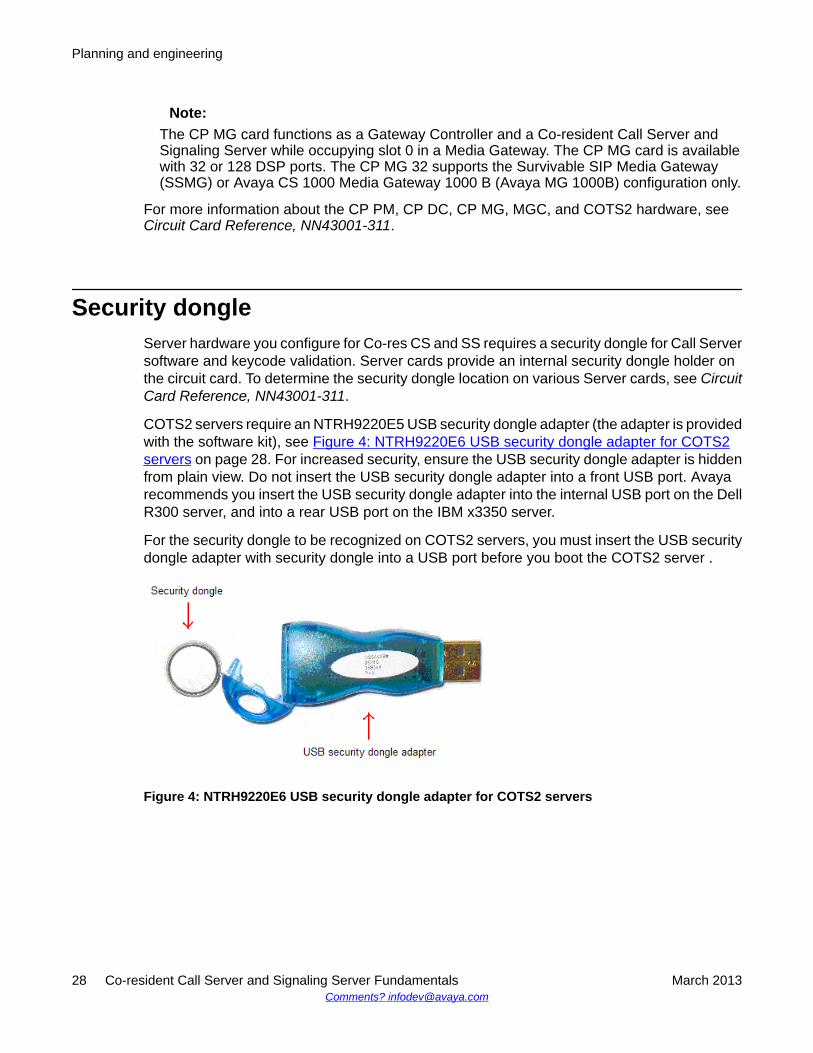
Security dongleServer hardware you configure for Co-res CS and SS requires a security dongle for Call Serversoftware and keycode validation. Server cards provide an internal security dongle holder onthe circuit card. To determine the security dongle location on various Server cards, see CircuitCard Reference, NN43001-311.
COTS2 servers require an NTRH9220E5 USB security dongle adapter (the adapter is providedwith the software kit), see Figure 4: NTRH9220E6 USB security dongle adapter for COTS2servers on page 28. For increased security, ensure the USB security dongle adapter is hiddenfrom plain view. Do not insert the USB security dongle adapter into a front USB port. Avayarecommends you insert the USB security dongle adapter into the internal USB port on the DellR300 server, and into a rear USB port on the IBM x3350 server.
For the security dongle to be recognized on COTS2 servers, you must insert the USB securitydongle adapter with security dongle into a USB port before you boot the COTS2 server .
Figure 4: NTRH9220E6 USB security dongle adapter for COTS2 servers
Planning and engineering
28 Co-resident Call Server and Signaling Server Fundamentals March 2013Comments? [email protected]
Ethernet port connectionsThe Server and Gateway Controller Ethernet ports must connect to the ELAN and TLANsubnets of the Avaya CS 1000E network. For Co-res CS and SS systems with an MGC card,see Server and MGC connections on page 29 for cabling options.
For Co-res CS and SS systems with a CP MG card, you can connect the IE (ELAN port) onthe CP MG faceplate to the ELAN subnet of the CS 1000E network, and connect the 2T (TLANport) on the CP MG faceplate to the TLAN subnet of the CS 1000E network. The CP MGEthernet connections between the Server and the Gateway Controller are embedded into theCP MG card, so no cabling is necessary to connect the Ethernet ports of the Server to theGateway Controller.
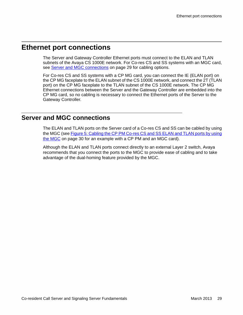
Server and MGC connectionsThe ELAN and TLAN ports on the Server card of a Co-res CS and SS can be cabled by usingthe MGC (see Figure 5: Cabling the CP PM Co-res CS and SS ELAN and TLAN ports by usingthe MGC on page 30 for an example with a CP PM and an MGC card).
Although the ELAN and TLAN ports connect directly to an external Layer 2 switch, Avayarecommends that you connect the ports to the MGC to provide ease of cabling and to takeadvantage of the dual-homing feature provided by the MGC.
Ethernet port connections
Co-resident Call Server and Signaling Server Fundamentals March 2013 29
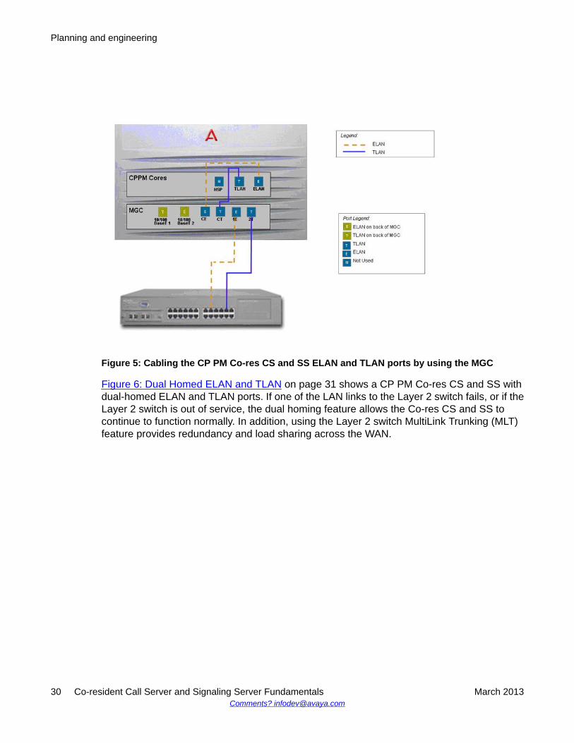
Figure 5: Cabling the CP PM Co-res CS and SS ELAN and TLAN ports by using the MGC
Figure 6: Dual Homed ELAN and TLAN on page 31 shows a CP PM Co-res CS and SS withdual-homed ELAN and TLAN ports. If one of the LAN links to the Layer 2 switch fails, or if theLayer 2 switch is out of service, the dual homing feature allows the Co-res CS and SS tocontinue to function normally. In addition, using the Layer 2 switch MultiLink Trunking (MLT)feature provides redundancy and load sharing across the WAN.
Planning and engineering
30 Co-resident Call Server and Signaling Server Fundamentals March 2013Comments? [email protected]
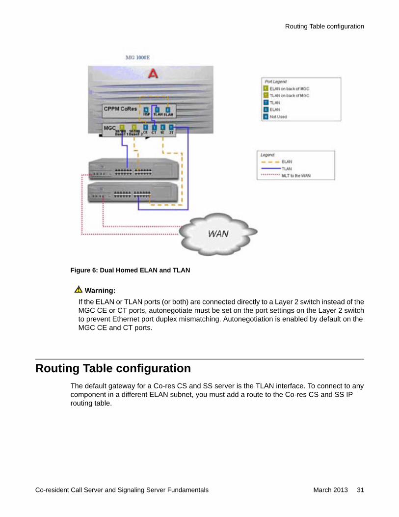
Figure 6: Dual Homed ELAN and TLAN
Warning:If the ELAN or TLAN ports (or both) are connected directly to a Layer 2 switch instead of theMGC CE or CT ports, autonegotiate must be set on the port settings on the Layer 2 switchto prevent Ethernet port duplex mismatching. Autonegotiation is enabled by default on theMGC CE and CT ports.
Routing Table configurationThe default gateway for a Co-res CS and SS server is the TLAN interface. To connect to anycomponent in a different ELAN subnet, you must add a route to the Co-res CS and SS IProuting table.
Routing Table configuration
Co-resident Call Server and Signaling Server Fundamentals March 2013 31
The following are examples of scenario where route configuration is required:
• Geographic Redundancy (GR) system where the Co-res CS and SS server is the PrimaryCall Server (PCS), the Secondary Call Server (SCS) or the Survivable Media Gateway(SMG) and the PCS, SCS and the SMG are not in the same subnet.
• CS 1000E Co-res CS and SS system with distributed Media Gateways. This is a non-GRsystem with Media Gateways that are in a different subnet than the Co-res CS and SSserver.
• CS1000E Co-res CS and SS system where the Telephony Manager (TM) is in a differentsubnet than the Co-res CS and SS server.
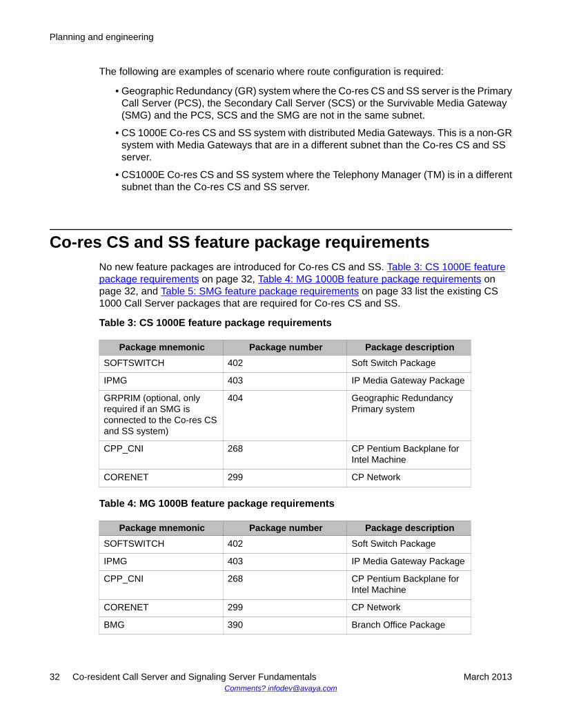
Co-res CS and SS feature package requirementsNo new feature packages are introduced for Co-res CS and SS. Table 3: CS 1000E featurepackage requirements on page 32, Table 4: MG 1000B feature package requirements onpage 32, and Table 5: SMG feature package requirements on page 33 list the existing CS1000 Call Server packages that are required for Co-res CS and SS.
Table 3: CS 1000E feature package requirements
Package mnemonic Package number Package descriptionSOFTSWITCH 402 Soft Switch Package
IPMG 403 IP Media Gateway Package
GRPRIM (optional, onlyrequired if an SMG isconnected to the Co-res CSand SS system)
404 Geographic RedundancyPrimary system
CPP_CNI 268 CP Pentium Backplane forIntel Machine
CORENET 299 CP Network
Table 4: MG 1000B feature package requirements
Package mnemonic Package number Package descriptionSOFTSWITCH 402 Soft Switch Package
IPMG 403 IP Media Gateway Package
CPP_CNI 268 CP Pentium Backplane forIntel Machine
CORENET 299 CP Network
BMG 390 Branch Office Package
Planning and engineering
32 Co-resident Call Server and Signaling Server Fundamentals March 2013Comments? [email protected]
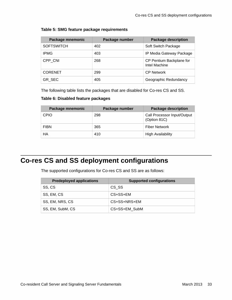
Table 5: SMG feature package requirements
Package mnemonic Package number Package descriptionSOFTSWITCH 402 Soft Switch Package
IPMG 403 IP Media Gateway Package
CPP_CNI 268 CP Pentium Backplane forIntel Machine
CORENET 299 CP Network
GR_SEC 405 Geographic Redundancy
The following table lists the packages that are disabled for Co-res CS and SS.
Table 6: Disabled feature packages
Package mnemonic Package number Package descriptionCPIO 298 Call Processor Input/Output
(Option 81C)
FIBN 365 Fiber Network
HA 410 High Availability
Co-res CS and SS deployment configurationsThe supported configurations for Co-res CS and SS are as follows:
Predeployed applications Supported configurationsSS, CS CS_SS
SS, EM, CS CS+SS+EM
SS, EM, NRS, CS CS+SS+NRS+EM
SS, EM, SubM, CS CS+SS+EM_SubM
Co-res CS and SS deployment configurations
Co-resident Call Server and Signaling Server Fundamentals March 2013 33
Signaling Server deployment limitationsThere are limitations when deploying other Signaling Servers with a Co-res CS and SS system:
• Installing a 2nd TPS (leader and follower) will not give true redundancy for the TPS. If theCo-res system itself fails, then the 2nd TPS has no place to register.
• Installing a Co-res CS and SS system means that the user has no redundancy on the CallServer or with the Signaling server applications. The only exception to this is the NRS.
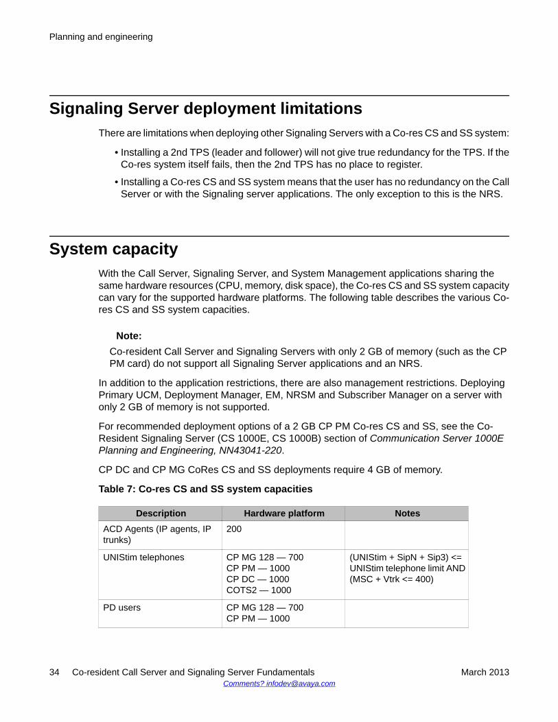
System capacityWith the Call Server, Signaling Server, and System Management applications sharing thesame hardware resources (CPU, memory, disk space), the Co-res CS and SS system capacitycan vary for the supported hardware platforms. The following table describes the various Co-res CS and SS system capacities.
Note:Co-resident Call Server and Signaling Servers with only 2 GB of memory (such as the CPPM card) do not support all Signaling Server applications and an NRS.
In addition to the application restrictions, there are also management restrictions. DeployingPrimary UCM, Deployment Manager, EM, NRSM and Subscriber Manager on a server withonly 2 GB of memory is not supported.
For recommended deployment options of a 2 GB CP PM Co-res CS and SS, see the Co-Resident Signaling Server (CS 1000E, CS 1000B) section of Communication Server 1000EPlanning and Engineering, NN43041-220.
CP DC and CP MG CoRes CS and SS deployments require 4 GB of memory.
Table 7: Co-res CS and SS system capacities
Description Hardware platform NotesACD Agents (IP agents, IPtrunks)
200
UNIStim telephones CP MG 128 — 700CP PM — 1000CP DC — 1000COTS2 — 1000
(UNIStim + SipN + Sip3) <=UNIStim telephone limit AND(MSC + Vtrk <= 400)
PD users CP MG 128 — 700CP PM — 1000
Planning and engineering
34 Co-resident Call Server and Signaling Server Fundamentals March 2013Comments? [email protected]
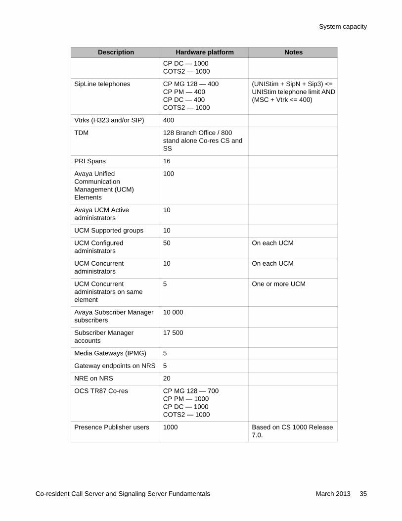
Description Hardware platform NotesCP DC — 1000COTS2 — 1000
SipLine telephones CP MG 128 — 400CP PM — 400CP DC — 400COTS2 — 1000
(UNIStim + SipN + Sip3) <=UNIStim telephone limit AND(MSC + Vtrk <= 400)
Vtrks (H323 and/or SIP) 400
TDM 128 Branch Office / 800stand alone Co-res CS andSS
PRI Spans 16
Avaya UnifiedCommunicationManagement (UCM)Elements
100
Avaya UCM Activeadministrators
10
UCM Supported groups 10
UCM Configuredadministrators
50 On each UCM
UCM Concurrentadministrators
10 On each UCM
UCM Concurrentadministrators on sameelement
5 One or more UCM
Avaya Subscriber Managersubscribers
10 000
Subscriber Manageraccounts
17 500
Media Gateways (IPMG) 5
Gateway endpoints on NRS 5
NRE on NRS 20
OCS TR87 Co-res CP MG 128 — 700CP PM — 1000CP DC — 1000COTS2 — 1000
Presence Publisher users 1000 Based on CS 1000 Release7.0.
System capacity
Co-resident Call Server and Signaling Server Fundamentals March 2013 35
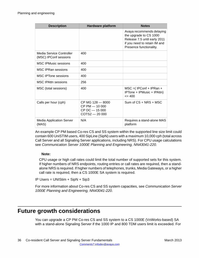
Description Hardware platform NotesAvaya recommends delayingthe upgrade to CS 1000Release 7.5 until early 2011if you need to retain IM andPresence functionality.
Media Service Controller(MSC) IPConf sessions
400
MSC IPMusic sessions 400
MSC IPRan sessions 400
MSC IPTone sessions 400
MSC IPAttn sessions 256
MSC (total sessions) 400 MSC =( IPConf + IPRan +IPTone + IPMusic + IPAttn)<= 400
Calls per hour (cph) CP MG 128 — 8000CP PM — 10 000CP DC — 15 000COTS2 — 20 000
Sum of CS + NRS + MSC
Media Application Server(MAS)
N/A Requires a stand-alone MASplatform
An example CP PM based Co-res CS and SS system within the supported line size limit couldcontain 600 UniSTIM users, 400 SipLine (SipN) users with a maximum 10,000 cph (total acrossCall Server and all Signaling Server applications, including NRS). For CPU usage calculationssee Communication Server 1000E Planning and Engineering, NN43041-220.
Note:CPU usage or high call rates could limit the total number of supported sets for this system.If higher numbers of NRS endpoints, routing entries or call rates are required, then a stand-alone NRS is required. If higher numbers of telephones, trunks, Media Gateways, or a highercall rate is required, then a CS 1000E SA system is required.
IP Users = UNIStim + SipN + Sip3
For more information about Co-res CS and SS system capacities, see Communication Server1000E Planning and Engineering, NN43041-220.
Future growth considerationsYou can upgrade a CP PM Co-res CS and SS system to a CS 1000E (VxWorks-based) SAwith a stand-alone Signaling Server if the 1000 IP and 800 TDM users limit is exceeded. For
Planning and engineering
36 Co-resident Call Server and Signaling Server Fundamentals March 2013Comments? [email protected]
details see Communication Server 1000E Planning and Engineering, NN43041-220 and LinuxPlatform Base and Applications Installation and Commissioning, NN43001-315.
IP address considerations
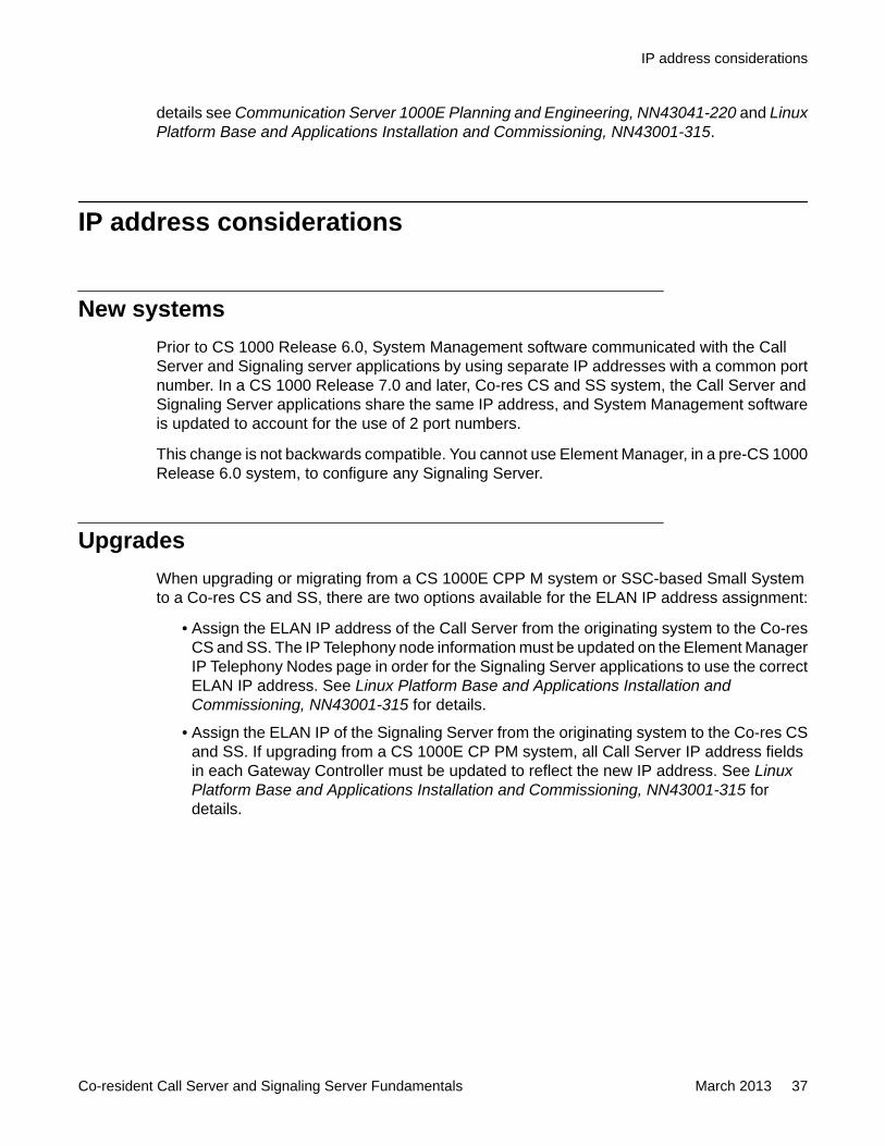
New systemsPrior to CS 1000 Release 6.0, System Management software communicated with the CallServer and Signaling server applications by using separate IP addresses with a common portnumber. In a CS 1000 Release 7.0 and later, Co-res CS and SS system, the Call Server andSignaling Server applications share the same IP address, and System Management softwareis updated to account for the use of 2 port numbers.
This change is not backwards compatible. You cannot use Element Manager, in a pre-CS 1000Release 6.0 system, to configure any Signaling Server.
UpgradesWhen upgrading or migrating from a CS 1000E CPP M system or SSC-based Small Systemto a Co-res CS and SS, there are two options available for the ELAN IP address assignment:
• Assign the ELAN IP address of the Call Server from the originating system to the Co-resCS and SS. The IP Telephony node information must be updated on the Element ManagerIP Telephony Nodes page in order for the Signaling Server applications to use the correctELAN IP address. See Linux Platform Base and Applications Installation andCommissioning, NN43001-315 for details.
• Assign the ELAN IP of the Signaling Server from the originating system to the Co-res CSand SS. If upgrading from a CS 1000E CP PM system, all Call Server IP address fieldsin each Gateway Controller must be updated to reflect the new IP address. See LinuxPlatform Base and Applications Installation and Commissioning, NN43001-315 fordetails.
IP address considerations
Co-resident Call Server and Signaling Server Fundamentals March 2013 37
Planning and engineering
38 Co-resident Call Server and Signaling Server Fundamentals March 2013Comments? [email protected]
Chapter 6: Installation and commissioning
IntroductionThis chapter contains software installation information. For information on hardwareinstallations, see Communication Server 1000E Installation and Commissioning,NN43041-310.
A Co-res CS and SS software installation consists of two phases:
• Avaya Communication Server 1000 (Avaya CS 1000) Linux Base installation
• Application installation
Two separate installation media are provided. One contains the CS 1000 Linux Base imageand the other contains the Call Server, Signaling Server, and system management applicationsoftware.
The CP PM, CP MG, CP DC, and COTS2 server hard drives from Avaya ship with the CS 1000Linux Base Operating System pre-installed.
Pre-installation checklistThe CP MG, CP DC, and COTS2 servers meet the requirements for Co-res CS and SS. Nopre-installation steps are necessary beyond installing the server hardware, security dongle,and connecting the server to the network.
The Co-res CS and SS requires a CP PM card with a 40 GB hard drive and 2 GB of memory.The CP PM version 1 hardware (NTDW61 and NTDW99BAE6) must run BIOS Release 18 orlater to support Co-res CS and SS. The CP PM version 2 (NTDW99CAE6) meets therequirements for Co-res CS and SS. CP PM version 2 includes an updated hardware design,BIOS, and boot manager.
You must perform the following procedures before any installation of a CP PM based Co-resCS and SS to ensure the hardware meets the preceding requirements.
Co-resident Call Server and Signaling Server Fundamentals March 2013 39
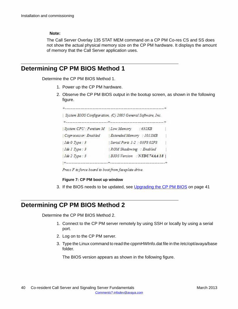
Note:The Call Server Overlay 135 STAT MEM command on a CP PM Co-res CS and SS doesnot show the actual physical memory size on the CP PM hardware. It displays the amountof memory that the Call Server application uses.
Determining CP PM BIOS Method 1Determine the CP PM BIOS Method 1.
1. Power up the CP PM hardware.
2. Observe the CP PM BIOS output in the bootup screen, as shown in the followingfigure.
Figure 7: CP PM boot up window
3. If the BIOS needs to be updated, see Upgrading the CP PM BIOS on page 41
Determining CP PM BIOS Method 2Determine the CP PM BIOS Method 2.
1. Connect to the CP PM server remotely by using SSH or locally by using a serialport.
2. Log on to the CP PM server.
3. Type the Linux command to read the cppmHWInfo.dat file in the /etc/opt/avaya/basefolder.
The BIOS version appears as shown in the following figure.
Installation and commissioning
40 Co-resident Call Server and Signaling Server Fundamentals March 2013Comments? [email protected]
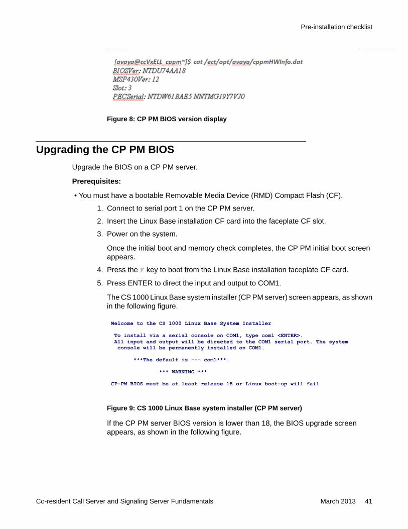
Figure 8: CP PM BIOS version display
Upgrading the CP PM BIOSUpgrade the BIOS on a CP PM server.
Prerequisites:
• You must have a bootable Removable Media Device (RMD) Compact Flash (CF).
1. Connect to serial port 1 on the CP PM server.
2. Insert the Linux Base installation CF card into the faceplate CF slot.
3. Power on the system.
Once the initial boot and memory check completes, the CP PM initial boot screenappears.
4. Press the F key to boot from the Linux Base installation faceplate CF card.
5. Press ENTER to direct the input and output to COM1.
The CS 1000 Linux Base system installer (CP PM server) screen appears, as shownin the following figure.
Figure 9: CS 1000 Linux Base system installer (CP PM server)
If the CP PM server BIOS version is lower than 18, the BIOS upgrade screenappears, as shown in the following figure.
Pre-installation checklist
Co-resident Call Server and Signaling Server Fundamentals March 2013 41
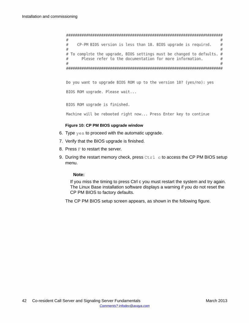
Figure 10: CP PM BIOS upgrade window
6. Type yes to proceed with the automatic upgrade.
7. Verify that the BIOS upgrade is finished.
8. Press F to restart the server.
9. During the restart memory check, press Ctrl c to access the CP PM BIOS setupmenu.
Note:If you miss the timing to press Ctrl c you must restart the system and try again.The Linux Base installation software displays a warning if you do not reset theCP PM BIOS to factory defaults.
The CP PM BIOS setup screen appears, as shown in the following figure.
Installation and commissioning
42 Co-resident Call Server and Signaling Server Fundamentals March 2013Comments? [email protected]
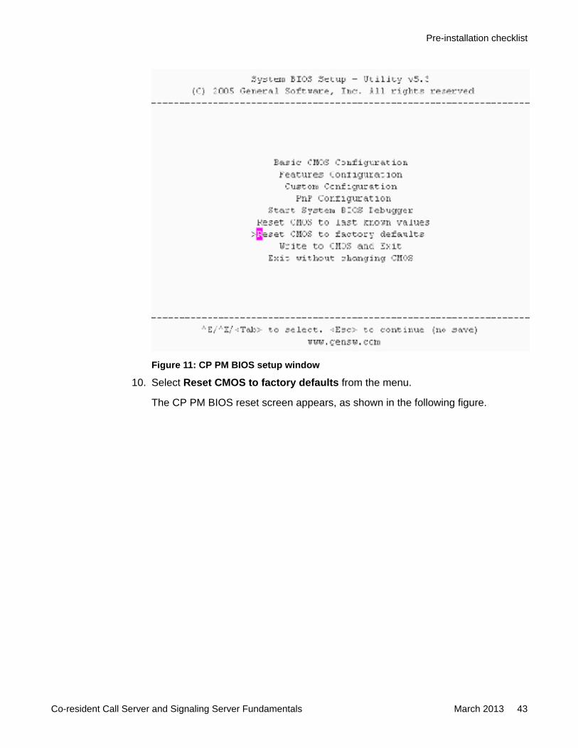
Figure 11: CP PM BIOS setup window
10. Select Reset CMOS to factory defaults from the menu.
The CP PM BIOS reset screen appears, as shown in the following figure.
Pre-installation checklist
Co-resident Call Server and Signaling Server Fundamentals March 2013 43
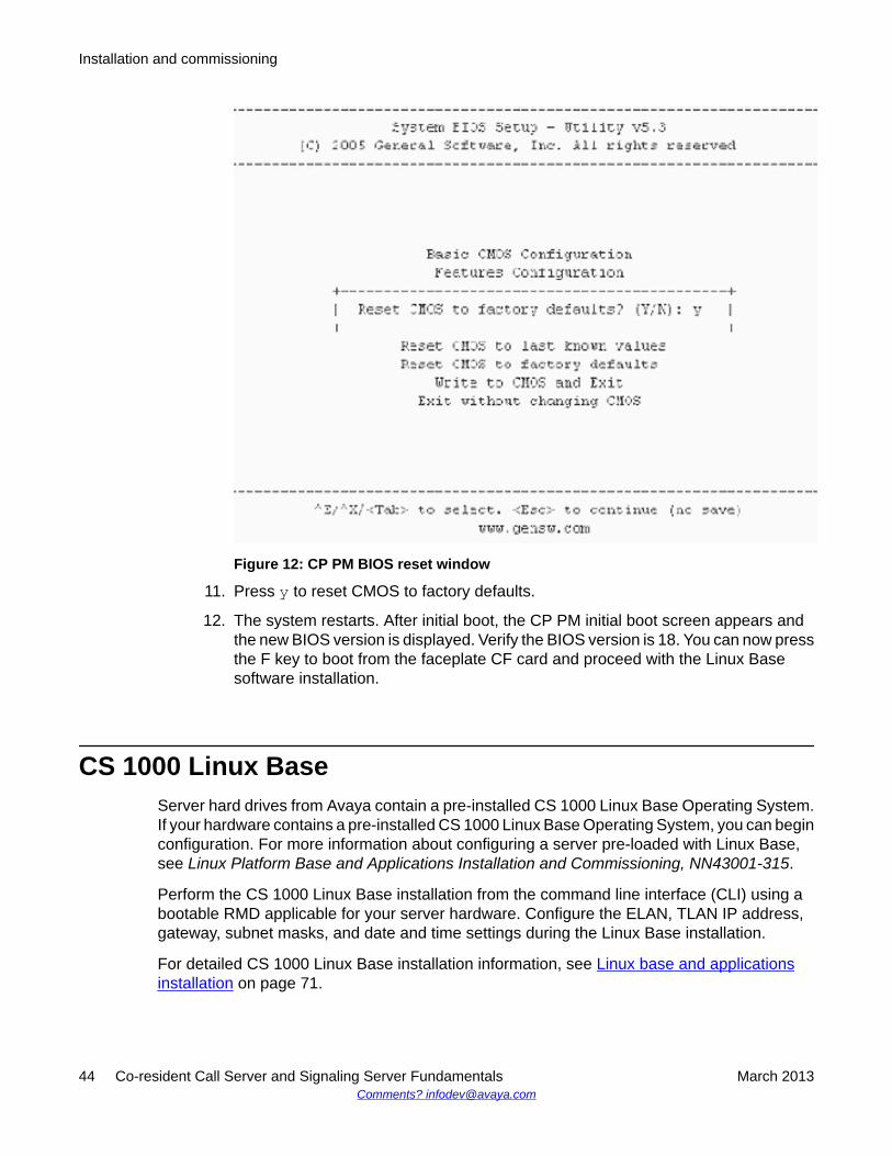
Figure 12: CP PM BIOS reset window
11. Press y to reset CMOS to factory defaults.
12. The system restarts. After initial boot, the CP PM initial boot screen appears andthe new BIOS version is displayed. Verify the BIOS version is 18. You can now pressthe F key to boot from the faceplate CF card and proceed with the Linux Basesoftware installation.
CS 1000 Linux BaseServer hard drives from Avaya contain a pre-installed CS 1000 Linux Base Operating System.If your hardware contains a pre-installed CS 1000 Linux Base Operating System, you can beginconfiguration. For more information about configuring a server pre-loaded with Linux Base,see Linux Platform Base and Applications Installation and Commissioning, NN43001-315.
Perform the CS 1000 Linux Base installation from the command line interface (CLI) using abootable RMD applicable for your server hardware. Configure the ELAN, TLAN IP address,gateway, subnet masks, and date and time settings during the Linux Base installation.
For detailed CS 1000 Linux Base installation information, see Linux base and applicationsinstallation on page 71.
Installation and commissioning
44 Co-resident Call Server and Signaling Server Fundamentals March 2013Comments? [email protected]
Co-res CS and SS application installationPerform the application installation on the Co-res CS and SS (and stand-alone Linux-basedCS 1000 servers) using UCM Deployment Manager.
Deployment Manager provides an end-to-end installation and commissioning of Linux Baseand applications. Deployment Manager provides a simplified and unified solution that enablesnetwork installation of Linux Base on target servers. The Primary security server is theDeployment Server.
For more information about Deployment Manager, Linux Base, and application installation, seeLinux Platform Base and Applications Installation and Commissioning, NN43001–315.
Call Server keycode upload and validation, language anddatabase selection
The keycode file is uploaded, and language and database selection occurs during the Linuxserver preconfiguration stage. The keycode is not validated on the target system at this stage;however, minimal prevalidation occurs from the Deployment Server. The language anddatabase fields are configured after the keycode prevalidation is accepted. For moreinformation about preconfiguring the deployment targets and keycode validation errormessages, see Linux Platform Base and Applications Installation and Commissioning,NN43001–315.
You can use the Deployment Manager to select Default Database, Existing Database,Customer Database on Client Machine, or Customer Database on Deployment Server USB.The existing database selection appliesonly to upgrades and not new installations. Thecustomer database selection allows the user to upload a Call Server database from the clientmachine or from a USB device connected directly to the server hosting the DeploymentManager (primary security server).
Co-res CS and SS application installation
Co-resident Call Server and Signaling Server Fundamentals March 2013 45
Installation and commissioning
46 Co-resident Call Server and Signaling Server Fundamentals March 2013Comments? [email protected]
Chapter 7: Upgrades
IntroductionThis section provides information on upgrading to an Avaya Communication Server 1000 (CS1000) Co-res CS and SS system.
Supported upgrade pathsFor the Call Server application, the supported upgrade paths can be categorized as follows:
• migration from an SSC-based Small System. For details, see Migration from an SSC-based small system on page 53
• upgrade from a CS 1000 Release 7.0 or earlier version of Avaya Communication Server1000E CP PII, CP PIV or CP PM Call Server. For details, see Linux Platform Base andApplications Installation and Commissioning, NN43001-315
• upgrade from a Release 7.0 CP PM Co-res CS and SS (application software versionupgrade)
HardwareThe Co-resident CS and SS can be deployed to various hardware platforms. For CS 1000Release 7.5 and later, the Co-resident CS and SS supports the following Servers:
• Common Processor Pentium Mobile (CP PM) card• Common Processor Media Gateway (CP MG) card• Common Processor Dual Core (CP DC) card• IBM x3350 and Dell R300 Commercial off-the-shelf (COTS) servers (COTS2)
If you are upgrading an existing Avaya CS 1000E system from a CP PII or CP PIV Call Server,you must replace the your existing hardware with a supported Server from the preceding list,and upgrade the software. For more information, see Communication Server 1000E HardwareUpgrades, NN43041-464
Co-resident Call Server and Signaling Server Fundamentals March 2013 47

The Server cards install in Media Gateway IPE slots, the COTS servers install in standard 19inch racks.
One Gateway Controller is required in each Media Gateway cabinet or chassis. The GatewayController can be an MGC card or a CP MG card.
Note:The CP MG card functions as a Gateway Controller and a Server while occupying only oneslot in a Media Gateway. The CP MG card is available with 32 or 128 DSP ports.
Note:If you require IPv6 on CP PM or CP MG platforms, Avaya recommends that you use adedicated third-party hardware firewall.
For more information about the CP PM, CP DC, CP MG, MGC, and COTS2 hardware, seeCircuit Card Reference, NN43001-311.
CP PM hard drive and memory upgradesFor information on CP PM memory or hard drive upgrades, see Circuit Card Reference,NN43001-311.
• All CP PM cards require a minimum 40 GB hard drive and 2 GB of memory to supportCo-res CS and SS.
• When upgrading from CS 1000 Release 5.x, the Call Server requires a 1 GB memoryupgrade (for a total of 2 GB memory) and an FMD replacement with a 40 GB harddrive.
Note:When upgrading from a CS 1000 Release 5.x CP PM Call Server, remove the FMD CF cardafter installing the 40GB hard drive.
Co-resident CS and SS application software upgrade (7.0 to7.6)
For information on performing system upgrades and application deployment with DeploymentManager or accessing the local Deployment Manager, see Linux Base Platform Base andApplications Installation and Commissioning, NN43001-315.
Upgrades
48 Co-resident Call Server and Signaling Server Fundamentals March 2013Comments? [email protected]
Backing up the CS 1000E Call Server databaseUse existing backup and restore procedures to move the customer data from a CS 1000E CallServer to the new CS 1000E Co-res CS and SS. Back up the customer database to the RMDby using the LD 43 EDD command.
Installing or upgrading the Co-res CS and SS using the CS1000E Call Server database
Install the CS 1000E Call Server database on to the Co-res CS and SS by using theDeployment Manager. To deploy the Call Server application, the Deployment Managerprovides a menu to select the default, existing or customer database. You must use thecustomer database selection, to allow the backed-up customer database on the RMD to betransferred to the Co-res CS and SS. For complete information, see Linux Platform Base andApplications Installation and Commissioning, NN43001-315 .
Installing or upgrading the Co-res CS and SS without usingthe CS 1000E Call Server database
Complete the following procedure if the Co-res Call Server is upgraded or installed withoutusing the CS 1000E Call Server database.
Installing or upgrading the Co-res CS and SS without using the CS 1000E CallServer database
1. On the Call Server, leave the security domain. See Security ManagementFundamentals, NN43001-604.
2. On the call server, enter LD 117 and disable secure transfer. See SecurityManagement Fundamentals, NN43001-604.
3. On the Call Server, enter LD 143 and disable Centralized Software Download.4. Perform a software upgrade or re-installation on the Call Server.5. On the Call Server, enter LD 143 and perform a force upgrade on the MGC.
Note:A transfer of account database error message and banner file are displayed onthe end point terminal after the MGC reboots.
Backing up the CS 1000E Call Server database
Co-resident Call Server and Signaling Server Fundamentals March 2013 49
6. On the Call Server, join the security domain. See Security ManagementFundamentals, NN43001-604.
7. On the Call Server, enter LD 117 and enable secure transfer. See SecurityManagement Fundamentals, NN43001-604.
8. On the Call Server, perform a datadump to ensure SFTP is enabled using theupdated token.
9. Check to ensure the account database and banner file is updated on the MGC.
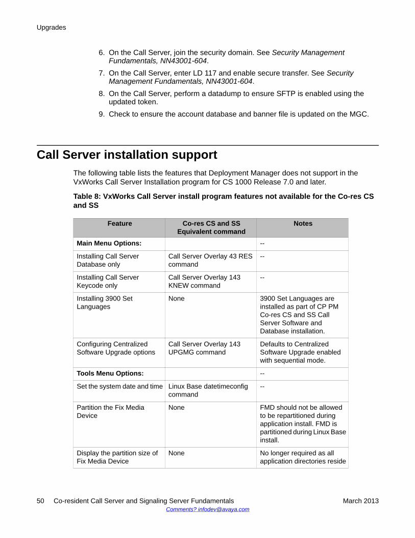
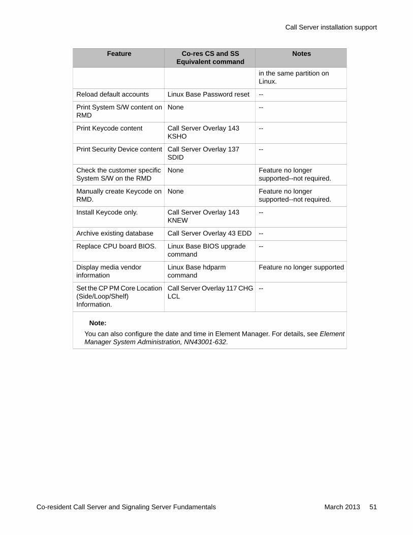
Call Server installation supportThe following table lists the features that Deployment Manager does not support in theVxWorks Call Server Installation program for CS 1000 Release 7.0 and later.
Table 8: VxWorks Call Server install program features not available for the Co-res CSand SS
Feature Co-res CS and SSEquivalent command
Notes
Main Menu Options: --
Installing Call ServerDatabase only
Call Server Overlay 43 REScommand
--
Installing Call ServerKeycode only
Call Server Overlay 143KNEW command
--
Installing 3900 SetLanguages
None 3900 Set Languages areinstalled as part of CP PMCo-res CS and SS CallServer Software andDatabase installation.
Configuring CentralizedSoftware Upgrade options
Call Server Overlay 143UPGMG command
Defaults to CentralizedSoftware Upgrade enabledwith sequential mode.
Tools Menu Options: --
Set the system date and time Linux Base datetimeconfigcommand
--
Partition the Fix MediaDevice
None FMD should not be allowedto be repartitioned duringapplication install. FMD ispartitioned during Linux Baseinstall.
Display the partition size ofFix Media Device
None No longer required as allapplication directories reside
Upgrades
50 Co-resident Call Server and Signaling Server Fundamentals March 2013Comments? [email protected]
Feature Co-res CS and SSEquivalent command
Notes
in the same partition onLinux.
Reload default accounts Linux Base Password reset --
Print System S/W content onRMD
None --
Print Keycode content Call Server Overlay 143KSHO
--
Print Security Device content Call Server Overlay 137SDID
--
Check the customer specificSystem S/W on the RMD
None Feature no longersupported--not required.
Manually create Keycode onRMD.
None Feature no longersupported--not required.
Install Keycode only. Call Server Overlay 143KNEW
--
Archive existing database Call Server Overlay 43 EDD --
Replace CPU board BIOS. Linux Base BIOS upgradecommand
--
Display media vendorinformation
Linux Base hdparmcommand
Feature no longer supported
Set the CP PM Core Location(Side/Loop/Shelf)Information.
Call Server Overlay 117 CHGLCL
--
Note:You can also configure the date and time in Element Manager. For details, see ElementManager System Administration, NN43001-632.
Call Server installation support
Co-resident Call Server and Signaling Server Fundamentals March 2013 51

Upgrades
52 Co-resident Call Server and Signaling Server Fundamentals March 2013Comments? [email protected]

Chapter 8: Migration from an SSC-basedsmall system
Supported migration pathsThe following table lists the supported migration paths from an SSC-based system to a Co-resident CS and SS based Avaya Communication Server 1000E (Avaya CS 1000E) system.
Table 9: Supported migration paths
Avaya Communication Server 1000 (CS1000) Release 6.0 or earlier
CS 1000 Release 7.6 System
Option 11C Small System CS 1000E Co-resident CS and SS
Avaya Communication Server 1000M (CS1000M) Small System Cabinet
CS 1000E Co-resident CS and SS
CS 1000M Small System Chassis CS 1000E Co-resident CS and SS
Avaya Communication Server 1000S (CS1000S) Small System
CS 1000E Co-resident CS and SS
Note:The minimum software release supported for SSC migration is Release 23.10.
Small System Call Server backup to an external driveThe Co-resident Call Server (CS) and Signaling Server (SS) supports converting thedatabases saved on the CS 1000 small system. The database must be converted due to afundamental difference between the small system, running an SSC, and a Co-resident CS andSS system. The difference is represented in how the format of the Terminal Number (TN) isdisplayed. The small system TN is displayed to the administrator using a two-field format, orcard-unit. In a Co-resident CS and SS system, the TN is displayed using a four-field format,or loop-shelf-card-unit. This four-field TN format is the same as those used in the CS 1000E.
When a small system database is converted to a large system database, the TNs areremapped. The end result is that the displayed TN changes during the conversion process.The administrator must be aware of the TN mapping. For example, a small system with an IPphone configured in TN 61-0 now has that same IP phone show up in 96-0-1-0 after the
Co-resident Call Server and Signaling Server Fundamentals March 2013 53
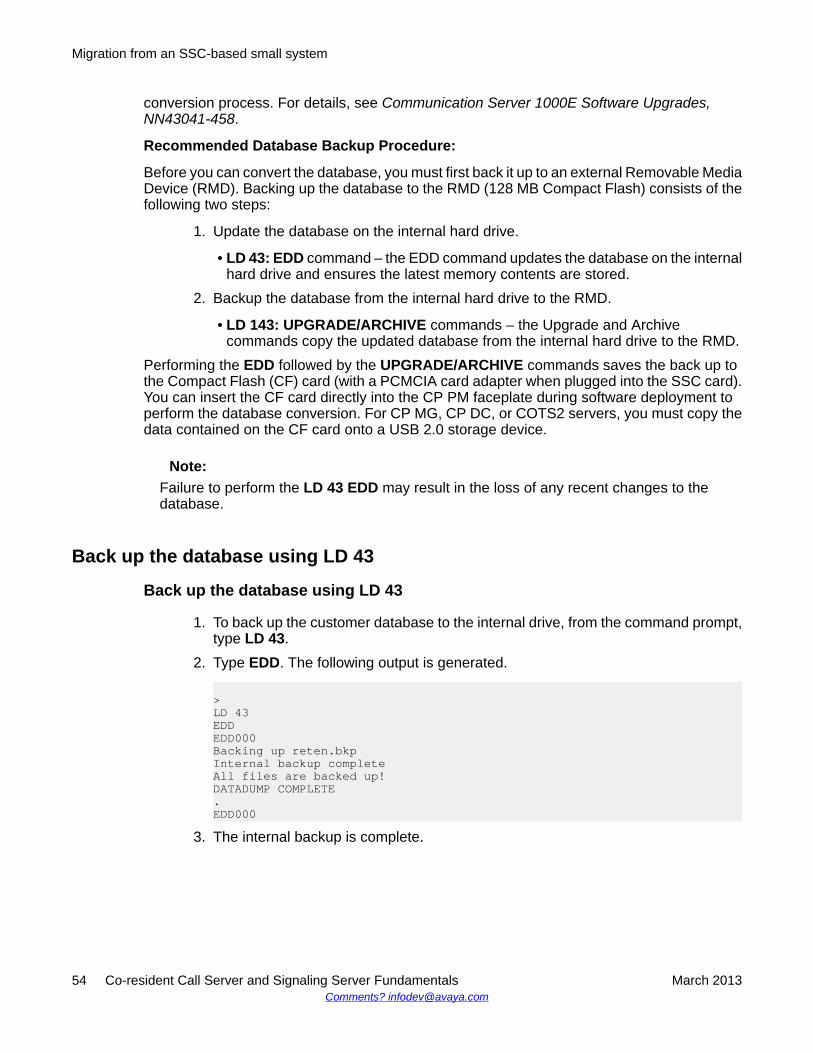
conversion process. For details, see Communication Server 1000E Software Upgrades,NN43041-458.
Recommended Database Backup Procedure:
Before you can convert the database, you must first back it up to an external Removable MediaDevice (RMD). Backing up the database to the RMD (128 MB Compact Flash) consists of thefollowing two steps:
1. Update the database on the internal hard drive.
• LD 43: EDD command – the EDD command updates the database on the internalhard drive and ensures the latest memory contents are stored.
2. Backup the database from the internal hard drive to the RMD.
• LD 143: UPGRADE/ARCHIVE commands – the Upgrade and Archivecommands copy the updated database from the internal hard drive to the RMD.
Performing the EDD followed by the UPGRADE/ARCHIVE commands saves the back up tothe Compact Flash (CF) card (with a PCMCIA card adapter when plugged into the SSC card).You can insert the CF card directly into the CP PM faceplate during software deployment toperform the database conversion. For CP MG, CP DC, or COTS2 servers, you must copy thedata contained on the CF card onto a USB 2.0 storage device.
Note:Failure to perform the LD 43 EDD may result in the loss of any recent changes to thedatabase.
Back up the database using LD 43
Back up the database using LD 43
1. To back up the customer database to the internal drive, from the command prompt,type LD 43.
2. Type EDD. The following output is generated.
>LD 43EDDEDD000Backing up reten.bkpInternal backup completeAll files are backed up!DATADUMP COMPLETE.EDD000
3. The internal backup is complete.
Migration from an SSC-based small system
54 Co-resident Call Server and Signaling Server Fundamentals March 2013Comments? [email protected]
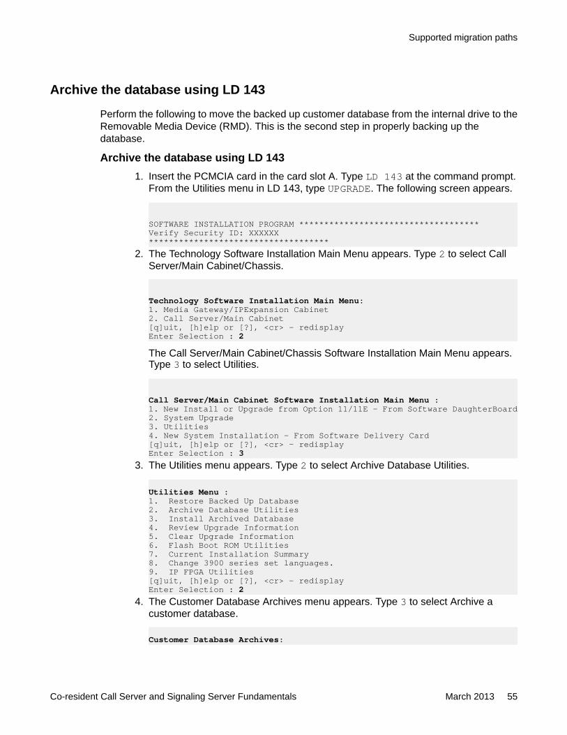
Archive the database using LD 143
Perform the following to move the backed up customer database from the internal drive to theRemovable Media Device (RMD). This is the second step in properly backing up thedatabase.
Archive the database using LD 1431. Insert the PCMCIA card in the card slot A. Type LD 143 at the command prompt.
From the Utilities menu in LD 143, type UPGRADE. The following screen appears.
SOFTWARE INSTALLATION PROGRAM ************************************Verify Security ID: XXXXXX************************************
2. The Technology Software Installation Main Menu appears. Type 2 to select CallServer/Main Cabinet/Chassis.
Technology Software Installation Main Menu:1. Media Gateway/IPExpansion Cabinet2. Call Server/Main Cabinet[q]uit, [h]elp or [?], <cr> - redisplayEnter Selection : 2
The Call Server/Main Cabinet/Chassis Software Installation Main Menu appears.Type 3 to select Utilities.
Call Server/Main Cabinet Software Installation Main Menu :1. New Install or Upgrade from Option 11/11E - From Software DaughterBoard2. System Upgrade3. Utilities4. New System Installation - From Software Delivery Card[q]uit, [h]elp or [?], <cr> - redisplayEnter Selection : 3
3. The Utilities menu appears. Type 2 to select Archive Database Utilities.
Utilities Menu :1. Restore Backed Up Database2. Archive Database Utilities3. Install Archived Database4. Review Upgrade Information5. Clear Upgrade Information6. Flash Boot ROM Utilities7. Current Installation Summary8. Change 3900 series set languages.9. IP FPGA Utilities[q]uit, [h]elp or [?], <cr> - redisplayEnter Selection : 2
4. The Customer Database Archives menu appears. Type 3 to select Archive acustomer database.
Customer Database Archives:
Supported migration paths
Co-resident Call Server and Signaling Server Fundamentals March 2013 55
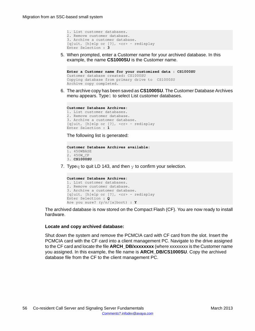
1. List customer databases.2. Remove customer database.3. Archive a customer database.[q]uit, [h]elp or [?], <cr> - redisplayEnter Selection : 3
5. When prompted, enter a Customer name for your archived database. In thisexample, the name CS1000SU is the Customer name.
Enter a Customer name for your customized data : CS1000SUCustomer database created: CS1000SUCopying database from primary drive to CS1000SUArchive copy completed.
6. The archive copy has been saved as CS1000SU. The Customer Database Archivesmenu appears. Type1 to select List customer databases.
Customer Database Archives:1. List customer databases.2. Remove customer database.3. Archive a customer database.[q]uit, [h]elp or [?], <cr> - redisplayEnter Selection : 1
The following list is generated:
Customer Database Archives available:1. 450WBASE2. 450W_CP3. CS1000SU
7. Typeq to quit LD 143, and then y to confirm your selection.
Customer Database Archives:1. List customer databases.2. Remove customer database.3. Archive a customer database.[q]uit, [h]elp or [?], <cr> - redisplayEnter Selection : QAre you sure? (y/n/[a]bort) : Y
The archived database is now stored on the Compact Flash (CF). You are now ready to installhardware.
Locate and copy archived database:
Shut down the system and remove the PCMCIA card with CF card from the slot. Insert thePCMCIA card with the CF card into a client management PC. Navigate to the drive assignedto the CF card and locate the file ARCH_DB/xxxxxxxx (where xxxxxxxx is the Customer nameyou assigned. In this example, the file name is ARCH_DB/CS1000SU. Copy the archiveddatabase file from the CF to the client management PC.
Migration from an SSC-based small system
56 Co-resident Call Server and Signaling Server Fundamentals March 2013Comments? [email protected]
Depending on the upgrade, the archived database file resides on either a Compact Flash card,a client management PC or a USB 2.0 storage device.
• For upgrades that use the CP PM card, you can insert the CF card containing the archiveddatabase directly into the faceplate of the card during the upgrade.
• For upgrades that use a CP MG, CP DC, or COTS2 server, you can copy the archiveddatabase from the client management PC to a USB 2.0 storage device using the clientmanagement PC.
• For upgrades using the Deployment Manager, the archived database file can also beuploaded from the client management PC to deployment server. When pre-configuring asystem using Deployment Manager, you are asked to specify the database to be used.The database choices include:
- Default Database: This is the pre-packaged database that is delivered with thesoftware and is can be used for a new installation.
- Existing Database: This option is used for a system upgrade.
- Customer Database on Client Machine: The database can be uploaded from anydevice connected to the client management PC.
- Customer database on Deployment Server USB:The database can be uploadedfrom a USB device connected directly to the server hosting the Deployment Manager(Primary Security Server).
For more information, see Linux Platform Base and Applications Installation andCommissioning, NN43001–315.
Choosing the cabinet or chassis and slot locationsA Media Gateway performs functions under the control of the CS 1000E Server. Traditionally,this Server was a CP PII or CP PIV in its own call server cabinet or chassis, The Server cardfor a Co-res CS and SS system sits in one of the Media Gateway IPE slots. Slot location isbased on the type of system:
• For Cabinet systems, refer to Cabinet on page 58• For Chassis systems, refer to Chassis on page 59• For Communication Server 1000S systems, refer to Avaya CS 1000S on page 62
Choosing the cabinet or chassis and slot locations
Co-resident Call Server and Signaling Server Fundamentals March 2013 57
CabinetThe Server card drives the Media Gateway through the Gateway Controller ELAN interfaceand therefore only uses the backplane for power. The following rules apply to the preferentialplacement of the Server card in the Media Gateway:
• The Server card cannot be placed in slot 0 of any Media Gateway. Slot 0 is reserved forthe Gateway Controller.
Note:The CP MG card can be placed in slot 0, the CP MG card functions as the Co-res CSand SS, and the Gateway Controller card.
• To allow for ease of cabling, the Server card may be placed in slots 1 through 10. ASignaling Server may be placed in slots 1 through 10 (see Figure 13: CP PM Co-res CSand SS system on page 59) or in another cabinet if necessary.
After the upgrade is complete, the Co-Res CS and SS system has a Gateway Controller in slot0 and a Server card in the main cabinet. The additional Media Gateways contain GatewayControllers, IPE cards, or another Server card running stand-alone Signaling Serverapplications.
Migration from an SSC-based small system
58 Co-resident Call Server and Signaling Server Fundamentals March 2013Comments? [email protected]
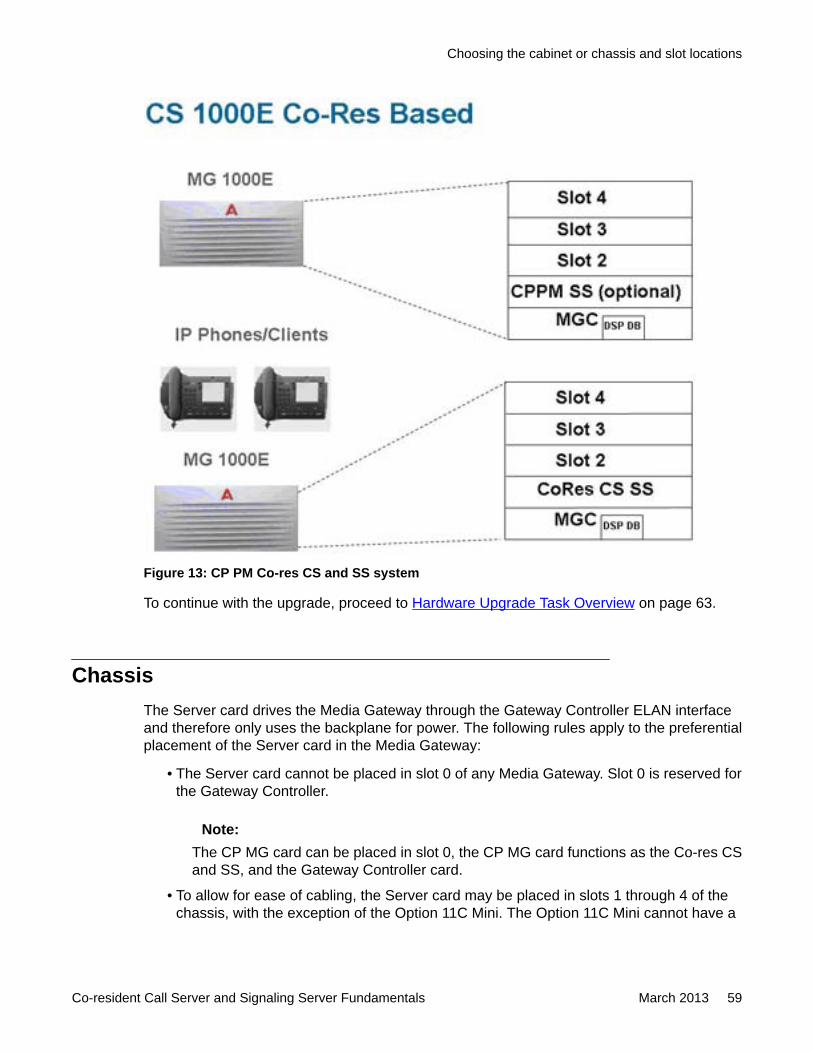
Figure 13: CP PM Co-res CS and SS system
To continue with the upgrade, proceed to Hardware Upgrade Task Overview on page 63.
ChassisThe Server card drives the Media Gateway through the Gateway Controller ELAN interfaceand therefore only uses the backplane for power. The following rules apply to the preferentialplacement of the Server card in the Media Gateway:
• The Server card cannot be placed in slot 0 of any Media Gateway. Slot 0 is reserved forthe Gateway Controller.
Note:The CP MG card can be placed in slot 0, the CP MG card functions as the Co-res CSand SS, and the Gateway Controller card.
• To allow for ease of cabling, the Server card may be placed in slots 1 through 4 of thechassis, with the exception of the Option 11C Mini. The Option 11C Mini cannot have a
Choosing the cabinet or chassis and slot locations
Co-resident Call Server and Signaling Server Fundamentals March 2013 59
Server card installed in slot 4 as this slot was originally allocated for the 48 port DLConly.
Figure 14: Option 11C or Communication Server 1000M Chassis call server on page 61shows an existing Option 11C or Communication Server 1000M Chassis call server with theSSC card. After the upgrade is complete, a Co-res CS and SS Chassis system resembles Figure 15: CP PM Co-res CS and SS system on page 61 with a Gateway Controller in slot0, and a Server card in the main chassis. The additional Media Gateways contain GatewayControllers, IPE cards, or another Server card running stand-alone Signaling Serverapplications.
Migration from an SSC-based small system
60 Co-resident Call Server and Signaling Server Fundamentals March 2013Comments? [email protected]
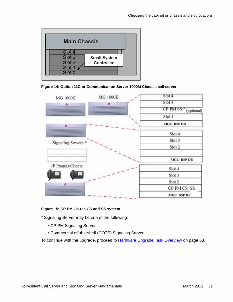
Figure 14: Option 11C or Communication Server 1000M Chassis call server
Figure 15: CP PM Co-res CS and SS system
* Signaling Server may be one of the following:
• CP PM Signaling Server
• Commercial off-the-shelf (COTS) Signaling Server
To continue with the upgrade, proceed to Hardware Upgrade Task Overview on page 63.
Choosing the cabinet or chassis and slot locations
Co-resident Call Server and Signaling Server Fundamentals March 2013 61
Avaya CS 1000SThe Server card drives the Media Gateway through the Gateway Controller ELAN interfaceand therefore only uses the backplane for power. The following rules apply to the preferentialplacement of the Server card in the Media Gateway:
• The Server card cannot be placed in slot 0 of any Media Gateway. Slot 0 is reserved forthe Gateway Controller.
Note:The CP MG card can be placed in slot 0, the CP MG card functions as the Co-res CSand SS, and the Gateway Controller card.
• To allow for ease of cabling, the Server card may be placed in slots 1 through 4 of thechassis, with the exception of the Option 11C Mini. The Option 11C Mini cannot have aServer card installed in slot 4 as this slot was originally allocated for the 48 port DLConly.
Figure 16: CS 1000S (NTDU30) call server on page 63 shows an existing CS 1000S CallServer with the SSC card. Once the upgrade is complete, a typical Co-res CS and SS Chassissystem will resemble Figure 13: CP PM Co-res CS and SS system on page 59 with a GatewayController in slot 0, and a Server card in the Media Gateway. The additional Media Gatewayscontain Gateway Controllers, IPE cards, or another Server card running stand-alone SignalingServer applications.
Migration from an SSC-based small system
62 Co-resident Call Server and Signaling Server Fundamentals March 2013Comments? [email protected]
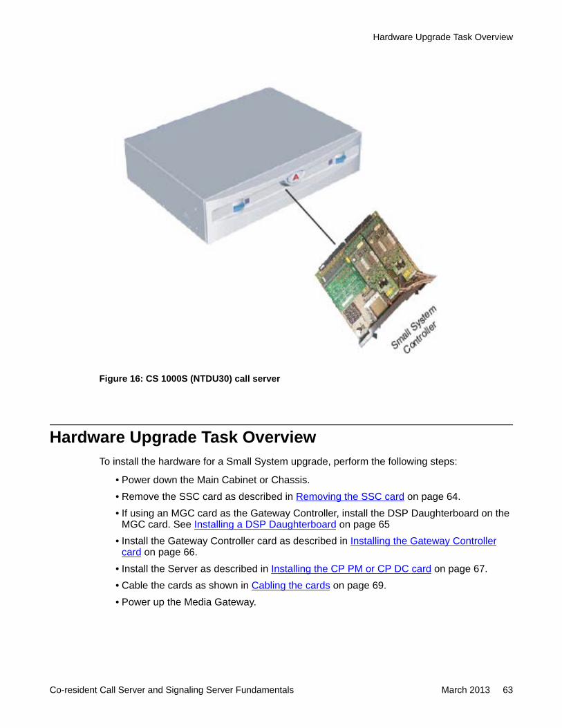
Figure 16: CS 1000S (NTDU30) call server
Hardware Upgrade Task OverviewTo install the hardware for a Small System upgrade, perform the following steps:
• Power down the Main Cabinet or Chassis.• Remove the SSC card as described in Removing the SSC card on page 64.• If using an MGC card as the Gateway Controller, install the DSP Daughterboard on the
MGC card. See Installing a DSP Daughterboard on page 65• Install the Gateway Controller card as described in Installing the Gateway Controller
card on page 66.• Install the Server as described in Installing the CP PM or CP DC card on page 67.• Cable the cards as shown in Cabling the cards on page 69.• Power up the Media Gateway.
Hardware Upgrade Task Overview
Co-resident Call Server and Signaling Server Fundamentals March 2013 63
• Enter the ‘mgcsetup’ menu and configure the IP parameters. For details, seeCommunication Server 1000E Installation and Commissioning, NN43041-310.
• Reboot the Gateway Controller
Card installationThe following sections describe the process required to install the Gateway Controller andServer cards.
Removing the SSC card
Removing the SSC card
1. Power down the system.2. Unlatch the SSC card.3. Remove the SSC card from its slot.
Important:The SSC card and dongle should be preserved for a minimum of five days. It is illegal tocontinue to run the system software on the existing SSC card. Please DESTROY orRETURN the SSC dongle to your local Avaya Repairs/Returns center upon confirmation ofa successful upgrade. No further orders will be accepted for the serial number since it willbe decommissioned and tracked in Avaya’s database. If the upgrade fails, you will not beable to revert back to the old system without the SSC card and dongle.
MGC DSP Daughterboard installation
The MGC card provides two expansion slots to add Digital Signal Processor (DSP) resourceswith DSP Daughterboards (DSP DB). Three DSP DB capacities are available:
• NTDW62 32-port DSP DB (DB-32)
• NTDW64 96-port DSP DB (DB-96)
• NTDW78 128-port DSP DB (DB-128)
You can configure any combination of the three available DSP DBs on an MGC card. The MGCcard supports a maximum of 256 DSP ports (two DB-128). For more information, see CircuitCard Reference, NN43001-311.
Important:Due to historical TN mapping for the Call Server software, even though the DSP channelswill occupy Card 0 in the Media Gateways, the TN (l s c u) 000 0 00 00 (ie unit 0 of card 0in the first IPMG <supl sh> = 000 0) is not available.
Migration from an SSC-based small system
64 Co-resident Call Server and Signaling Server Fundamentals March 2013Comments? [email protected]
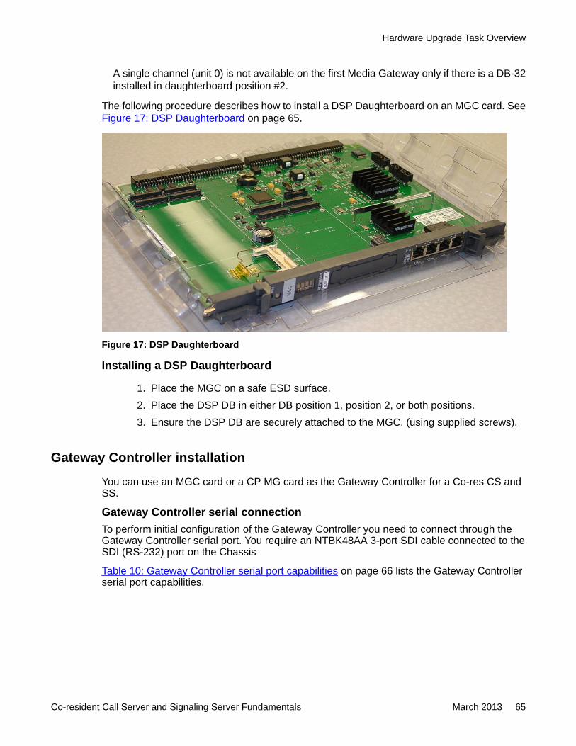
A single channel (unit 0) is not available on the first Media Gateway only if there is a DB-32installed in daughterboard position #2.
The following procedure describes how to install a DSP Daughterboard on an MGC card. SeeFigure 17: DSP Daughterboard on page 65.
Figure 17: DSP Daughterboard
Installing a DSP Daughterboard
1. Place the MGC on a safe ESD surface.2. Place the DSP DB in either DB position 1, position 2, or both positions.3. Ensure the DSP DB are securely attached to the MGC. (using supplied screws).
Gateway Controller installation
You can use an MGC card or a CP MG card as the Gateway Controller for a Co-res CS andSS.
Gateway Controller serial connectionTo perform initial configuration of the Gateway Controller you need to connect through theGateway Controller serial port. You require an NTBK48AA 3-port SDI cable connected to theSDI (RS-232) port on the Chassis
Table 10: Gateway Controller serial port capabilities on page 66 lists the Gateway Controllerserial port capabilities.
Hardware Upgrade Task Overview
Co-resident Call Server and Signaling Server Fundamentals March 2013 65
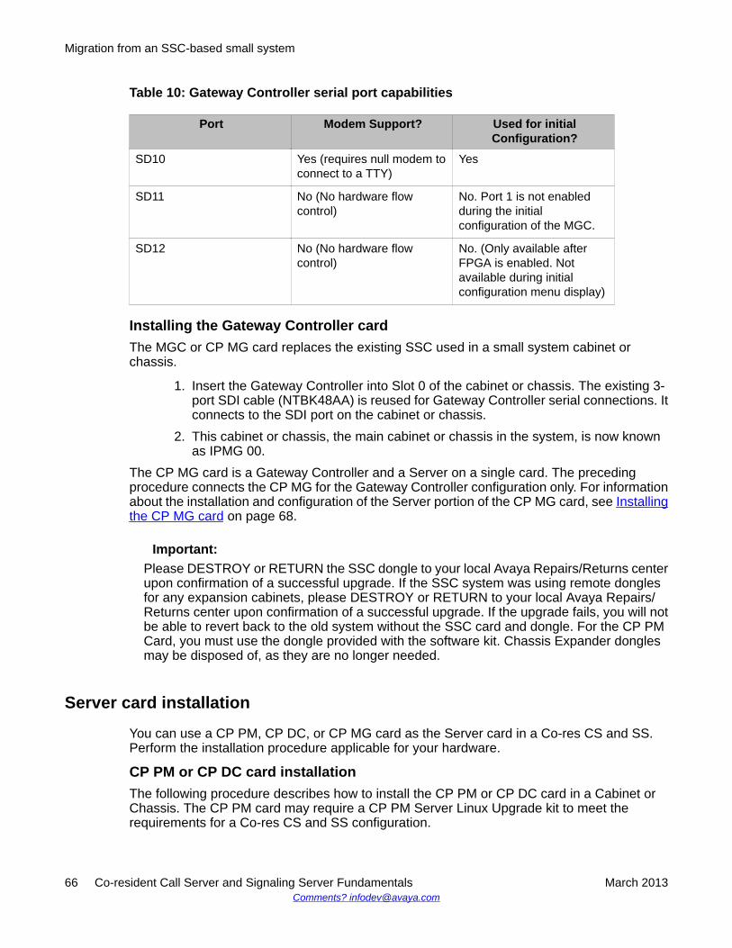
Table 10: Gateway Controller serial port capabilities
Port Modem Support? Used for initialConfiguration?
SD10 Yes (requires null modem toconnect to a TTY)
Yes
SD11 No (No hardware flowcontrol)
No. Port 1 is not enabledduring the initialconfiguration of the MGC.
SD12 No (No hardware flowcontrol)
No. (Only available afterFPGA is enabled. Notavailable during initialconfiguration menu display)
Installing the Gateway Controller cardThe MGC or CP MG card replaces the existing SSC used in a small system cabinet orchassis.
1. Insert the Gateway Controller into Slot 0 of the cabinet or chassis. The existing 3-port SDI cable (NTBK48AA) is reused for Gateway Controller serial connections. Itconnects to the SDI port on the cabinet or chassis.
2. This cabinet or chassis, the main cabinet or chassis in the system, is now knownas IPMG 00.
The CP MG card is a Gateway Controller and a Server on a single card. The precedingprocedure connects the CP MG for the Gateway Controller configuration only. For informationabout the installation and configuration of the Server portion of the CP MG card, see Installingthe CP MG card on page 68.
Important:Please DESTROY or RETURN the SSC dongle to your local Avaya Repairs/Returns centerupon confirmation of a successful upgrade. If the SSC system was using remote donglesfor any expansion cabinets, please DESTROY or RETURN to your local Avaya Repairs/Returns center upon confirmation of a successful upgrade. If the upgrade fails, you will notbe able to revert back to the old system without the SSC card and dongle. For the CP PMCard, you must use the dongle provided with the software kit. Chassis Expander donglesmay be disposed of, as they are no longer needed.
Server card installation
You can use a CP PM, CP DC, or CP MG card as the Server card in a Co-res CS and SS.Perform the installation procedure applicable for your hardware.
CP PM or CP DC card installationThe following procedure describes how to install the CP PM or CP DC card in a Cabinet orChassis. The CP PM card may require a CP PM Server Linux Upgrade kit to meet therequirements for a Co-res CS and SS configuration.
Migration from an SSC-based small system
66 Co-resident Call Server and Signaling Server Fundamentals March 2013Comments? [email protected]
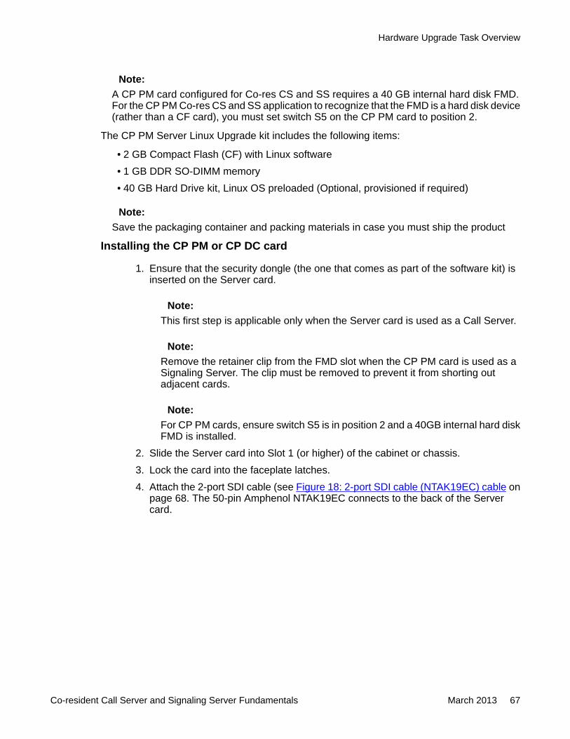
Note:A CP PM card configured for Co-res CS and SS requires a 40 GB internal hard disk FMD.For the CP PM Co-res CS and SS application to recognize that the FMD is a hard disk device(rather than a CF card), you must set switch S5 on the CP PM card to position 2.
The CP PM Server Linux Upgrade kit includes the following items:
• 2 GB Compact Flash (CF) with Linux software• 1 GB DDR SO-DIMM memory• 40 GB Hard Drive kit, Linux OS preloaded (Optional, provisioned if required)
Note:Save the packaging container and packing materials in case you must ship the product
Installing the CP PM or CP DC card
1. Ensure that the security dongle (the one that comes as part of the software kit) isinserted on the Server card.
Note:This first step is applicable only when the Server card is used as a Call Server.
Note:Remove the retainer clip from the FMD slot when the CP PM card is used as aSignaling Server. The clip must be removed to prevent it from shorting outadjacent cards.
Note:For CP PM cards, ensure switch S5 is in position 2 and a 40GB internal hard diskFMD is installed.
2. Slide the Server card into Slot 1 (or higher) of the cabinet or chassis.3. Lock the card into the faceplate latches.4. Attach the 2-port SDI cable (see Figure 18: 2-port SDI cable (NTAK19EC) cable on
page 68. The 50-pin Amphenol NTAK19EC connects to the back of the Servercard.
Hardware Upgrade Task Overview
Co-resident Call Server and Signaling Server Fundamentals March 2013 67
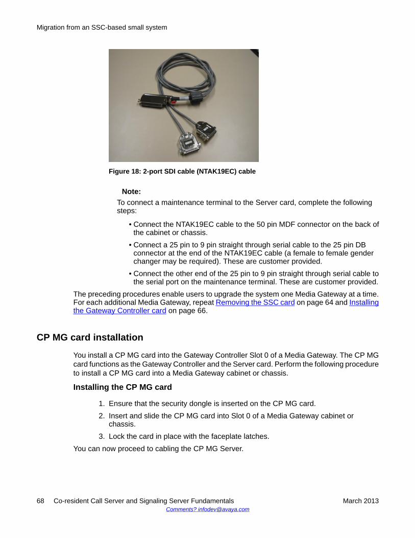
Figure 18: 2-port SDI cable (NTAK19EC) cable
Note:To connect a maintenance terminal to the Server card, complete the followingsteps:
• Connect the NTAK19EC cable to the 50 pin MDF connector on the back ofthe cabinet or chassis.
• Connect a 25 pin to 9 pin straight through serial cable to the 25 pin DBconnector at the end of the NTAK19EC cable (a female to female genderchanger may be required). These are customer provided.
• Connect the other end of the 25 pin to 9 pin straight through serial cable tothe serial port on the maintenance terminal. These are customer provided.
The preceding procedures enable users to upgrade the system one Media Gateway at a time.For each additional Media Gateway, repeat Removing the SSC card on page 64 and Installingthe Gateway Controller card on page 66.
CP MG card installation
You install a CP MG card into the Gateway Controller Slot 0 of a Media Gateway. The CP MGcard functions as the Gateway Controller and the Server card. Perform the following procedureto install a CP MG card into a Media Gateway cabinet or chassis.
Installing the CP MG card
1. Ensure that the security dongle is inserted on the CP MG card.2. Insert and slide the CP MG card into Slot 0 of a Media Gateway cabinet or
chassis.3. Lock the card in place with the faceplate latches.
You can now proceed to cabling the CP MG Server.
Migration from an SSC-based small system
68 Co-resident Call Server and Signaling Server Fundamentals March 2013Comments? [email protected]
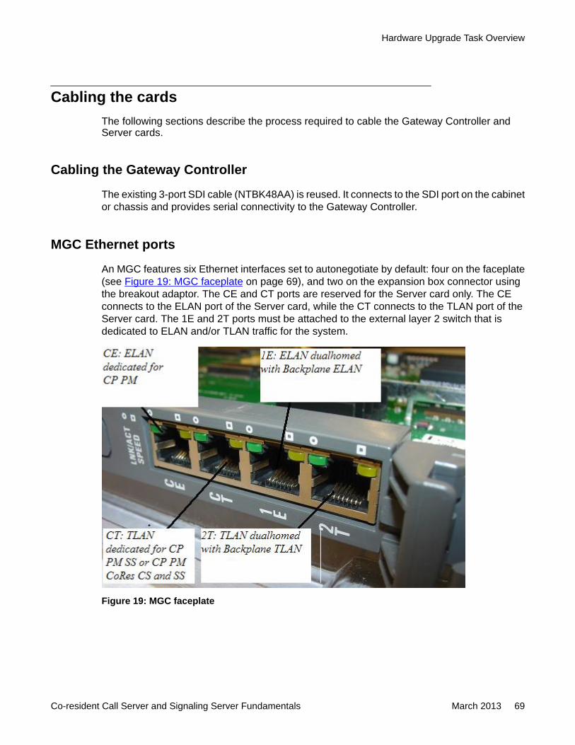
Cabling the cardsThe following sections describe the process required to cable the Gateway Controller andServer cards.
Cabling the Gateway Controller
The existing 3-port SDI cable (NTBK48AA) is reused. It connects to the SDI port on the cabinetor chassis and provides serial connectivity to the Gateway Controller.
MGC Ethernet ports
An MGC features six Ethernet interfaces set to autonegotiate by default: four on the faceplate(see Figure 19: MGC faceplate on page 69), and two on the expansion box connector usingthe breakout adaptor. The CE and CT ports are reserved for the Server card only. The CEconnects to the ELAN port of the Server card, while the CT connects to the TLAN port of theServer card. The 1E and 2T ports must be attached to the external layer 2 switch that isdedicated to ELAN and/or TLAN traffic for the system.
Figure 19: MGC faceplate
Hardware Upgrade Task Overview
Co-resident Call Server and Signaling Server Fundamentals March 2013 69
CP PM or CP DC card cabling
The COM (SDI) port of the CP PM and CP DC card is routed through the backplane of theshelf to the 50-pin Amphinol connector on the back of the shelf. An NTAK19EC cable is requiredto adapt the 50-pin Amphinol to a 25-pin DB connector. Port 0 is used for maintenance access,and Port 1 is for an external modem connection.
Connect the ELAN of the CP PM or CP DC card to the CE port of the Gateway Controller orto the VLAN of the external layer 2 switch that is dedicated to ELAN traffic for the system.
CP MG card cabling
The CP MG card is installed in Slot 0 and is uses the 3-port SDI cable for Gateway Controllerconfiguration. Perform the following procedure to cable the CP MG card for Server serial andLAN connections. An NTC325AAE6 serial port adapter kit is required.
Cabling the CP MG Server
1. Connect a Cat5e or Cat6 Ethernet cable to the TTY1 port on the CP MGfaceplate.
2. Connect a NTC326AAE6 serial port adapter (9-pin or 25-pin) to the other end of theEthernet cable.
3. Connect the Ethernet cable with adapter to a serial port on a maintenanceterminal.
Note:If you require a longer cable to reach your maintenance terminal, you can attacha standard serial port cable to the adapter for extended cable length.
4. Configure the maintenance terminal for VT-100 emulation, 9600 bps, 8,N,1.5. Connect the ELAN cable:
• Connect one end of a shielded Cat5e or Cat6 Ethernet cable to the 1E (ELAN)port on the CP MG faceplate.
• Connect the other end of the Ethernet cable to the ELAN subnet of the CS1000E system.
6. Connect the TLAN cable:
• Connect one end of a shielded Cat5e or Cat6 Ethernet cable to the 2T (TLAN)port on the CP MG faceplate.
• Connect the other end of the Ethernet cable to the TLAN subnet of the CS1000E system.
Migration from an SSC-based small system
70 Co-resident Call Server and Signaling Server Fundamentals March 2013Comments? [email protected]
Linux base and applications installationUse Deployment Manager on the Primary security server for an end-to-end installation andconfiguration of Linux Base and applications. Deployment Manager provides a simplified andunified solution that enables network installation of Linux Base on target servers. The Primarysecurity server is the Deployment Server. Install the Linux Base on the Primary security server(Deployment Server) using a local Linux Base installation media. Upgrade Linux Base on theMember and Backup servers over the network using Network File System (NFS). For moreinformation about Linux Base and application installation, see Linux Platform Base andApplications Installation and Commissioning, NN43001-315.
The CP MG, CP DC, and COTS2 Servers ship with Linux Base pre-installed. For moreinformation about configuring a server pre-loaded with Avaya Linux Base and deployingapplications, see Linux Platform Base and Applications Installation and Commissioning,NN43001-315.
Linux base and applications installation
Co-resident Call Server and Signaling Server Fundamentals March 2013 71

Migration from an SSC-based small system
72 Co-resident Call Server and Signaling Server Fundamentals March 2013Comments? [email protected]
Chapter 9: Patching
Patching the Co-res CS and SS
Note:For detailed information about patching Linux components using Central Patching Managerand local patching by Base Manager, see Linux Platform Base and Applications Installationand Commissioning, NN43001-315.
Support is available for two patch types for the Co-res CS and SS:
• Call Server Binary patches are currently used in Avaya Communication Server 1000(Avaya CS 1000) to patch the Call Server only. The file names for binary patches in VxELLfor the Call Server have the pxxxxx_x.cpl format. VxWorks file names have thepxxxxx.x.cpm format.
• Linux patches are used to patch the Signaling Server, Linux Base and any other Linuxbased applications excluding the Call Server.
You can perform patching from the CLI or Element Manager. Patch files are transferred to theplatform by using FTP/SFTP, a USB drive, or an RMD CF card. For detailed information aboutpatching using Element Manager, see Element Manager System Administration,NN43001-632.
Patching Call Server binary patchesThe method of deploying the Call Server binary patches on the Call Server using the CLI issimilar to deploying patches using the previous release of Avaya CS 1000 Call Server. Youpatch by using the CLI. You must place the binary patch files in the /var/opt/nortel/cs/fs/u/patchfolder. You must enter the pload, pins, poos, pstat and pout patching commands fromthe Call Server PDT shell.
Patching Call Server binary patches
1. Ensure the patch file is in the /var/opt/nortel/cs/fs/u/patch directory.2. Connect to the Co-res CS and SS remotely (ssh) or locally (serial port).3. Log on to the Co-res CS and SS.
Co-resident Call Server and Signaling Server Fundamentals March 2013 73
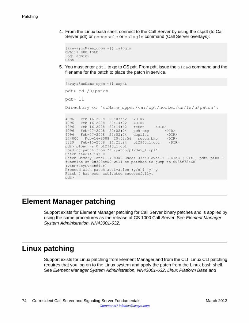
4. From the Linux bash shell, connect to the Call Server by using the cspdt (to CallServer pdt) or csconsole or cslogin command (Call Server overlays):
[avaya@ccName_cppm ~]$ csloginOVL111 000 IDLELogi admin2PASS
5. You must enter pdt1 to go to CS pdt. From pdt, issue the pload command and thefilename for the patch to place the patch in service.
[avaya@ccName_cppm ~]$ cspdtpdt> cd /u/patchpdt> llDirectory of ‘ccName_cppm:/var/opt/nortel/cs/fs/u/patch’:
4096 Feb-16-2008 20:03:52 <DIR>4096 Feb-16-2008 20:14:22 <DIR>4096 Feb-16-2008 20:14:42 reten <DIR>4096 Feb-07-2008 22:02:04 pch_tmp <DIR>4096 Feb-07-2008 22:02:04 deplist <DIR>144000 Feb-16-2008 20:03:56 reten.bkp <DIR>3829 Feb-15-2008 14:21:24 p12345_1.cpl <DIR>pdt> pload -s 0 p12345_1.cplLoading patch from "/u/patch/p12345_1.cpl”Patch handle is: 0Patch Memory Total: 4083KB Used: 335KB Avail: 3747KB ( 91% ) pdt> pins 0function at 0x308be00 will be patched to jump to 0x35f78e60 (vtnProxyEvHandler)Proceed with patch activation (y/n)? [y] yPatch 0 has been activated successfully.pdt>
Element Manager patchingSupport exists for Element Manager patching for Call Server binary patches and is applied byusing the same procedures as the release of CS 1000 Call Server. See Element ManagerSystem Administration, NN43001-632.
Linux patchingSupport exists for Linux patching from Element Manager and from the CLI. Linux CLI patchingrequires that you log on to the Linux system and apply the patch from the Linux bash shell.See Element Manager System Administration, NN43001-632, Linux Platform Base and
Patching
74 Co-resident Call Server and Signaling Server Fundamentals March 2013Comments? [email protected]
Applications Installation and Commissioning, NN43001-315 , and Unified CommunicationsManagement Common Services Fundamentals, NN43001-116.
Call Server deplistSupport exists for Call Server deplist and is applied by using the same procedures as theprevious release of CS 1000 Call Server.
Note:Co-res CS and SS supports installing a deplist from the FMD (hard drive) or RMD (USB, CFcard).
Call Server deplist
Co-resident Call Server and Signaling Server Fundamentals March 2013 75

Patching
76 Co-resident Call Server and Signaling Server Fundamentals March 2013Comments? [email protected]
Chapter 10: Feature operation
Call ServerThe Linux-based Call Server provides the same feature operation and feature managementas the VXWorks-based, with the following exceptions:
• Configuration and management of Network Time Protocol (NTP) occurs within the LinuxBase. Support is unavailable for LD 117 NTP management commands in CS 1000Release 6.0 and later.
• Support exists for CCBR backup and restore on Gateway Controller remote TTY ports.Support is unavailable for CCBR backup and restore on the Server card serial port.
• Support exists for Xmodem sx and rx commands on the Gateway Controller remote TTY(from the Call Server PDT shell). Support is available for the sx and rx commands fromthe Linux Shell.
• Configuration of Time of Day (TOD) management occurs in Linux Base. Support isunavailable for LD 2 TOD configuration commands. Support is unavailable for AttendantConsole Set Based Administration for TOD configuration and management. Support isonly available for the LD 2 TOD print command.
Co-resident Call Server and Signaling Server Fundamentals March 2013 77

Feature operation
78 Co-resident Call Server and Signaling Server Fundamentals March 2013Comments? [email protected]
Chapter 11: Configuration management
OAM User InterfaceWhile support exists for most of the existing Avaya Communication Server 1000E (Avaya CS1000E) Call Server and Signaling Server application user commands for Co-res CS and SS,some changes have been made to allow the Call Server and Signaling Server applications toco-reside and run as Linux applications. The new or modified user interfaces are focused inthe following areas:
• Access to the Co-res CS and SS• IP configuration and management• NTP configuration management• TOD configuration• Point-to-Point Protocol (PPP) configuration• File system layout for the Co-res CS and SS• Co-res CS and SS restart• Geographic Redundancy Survivable Media Gateway Configuration• Serial port configuration• Co-res CS and SS software version• Co-res CS and SS configuration/database backup and restore• Media Gateway Centralized Software Upgrade• location (loop and shelf) configuration• Overlay 137 Stat RMD commands• Overlay 117 security configurations• Accessing RMD and USB from Call Server PDT shell
Co-resident Call Server and Signaling Server Fundamentals March 2013 79
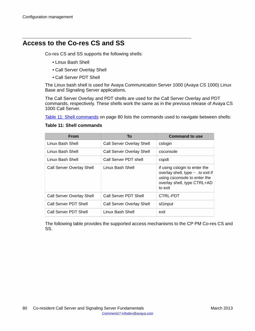
Access to the Co-res CS and SSCo-res CS and SS supports the following shells:
• Linux Bash Shell• Call Server Overlay Shell• Call Server PDT Shell
The Linux bash shell is used for Avaya Communication Server 1000 (Avaya CS 1000) LinuxBase and Signaling Server applications.
The Call Server Overlay and PDT shells are used for the Call Server Overlay and PDTcommands, respectively. These shells work the same as in the previous release of Avaya CS1000 Call Server.
Table 11: Shell commands on page 80 lists the commands used to navigate between shells:
Table 11: Shell commands
From To Command to useLinux Bash Shell Call Server Overlay Shell cslogin
Linux Bash Shell Call Server Overlay Shell csconsole
Linux Bash Shell Call Server PDT shell cspdt
Call Server Overlay Shell Linux Bash Shell if using cslogin to enter theoverlay shell, type ~ . to exit ifusing csconsole to enter theoverlay shell, type CTRL+ADto exit
Call Server Overlay Shell Call Server PDT Shell CTRL-PDT
Call Server PDT Shell Call Server Overlay Shell sl1input
Call Server PDT Shell Linux Bash Shell exit
The following table provides the supported access mechanisms to the CP PM Co-res CS andSS.
Configuration management
80 Co-resident Call Server and Signaling Server Fundamentals March 2013Comments? [email protected]
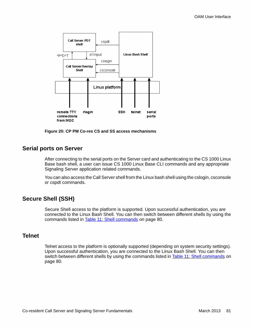
Figure 20: CP PM Co-res CS and SS access mechanisms
Serial ports on Server
After connecting to the serial ports on the Server card and authenticating to the CS 1000 LinuxBase bash shell, a user can issue CS 1000 Linux Base CLI commands and any appropriateSignaling Server application related commands.
You can also access the Call Server shell from the Linux bash shell using the cslogin, csconsoleor cspdt commands.
Secure Shell (SSH)
Secure Shell access to the platform is supported. Upon successful authentication, you areconnected to the Linux Bash Shell. You can then switch between different shells by using thecommands listed in Table 11: Shell commands on page 80.
Telnet
Telnet access to the platform is optionally supported (depending on system security settings).Upon successful authentication, you are connected to the Linux Bash Shell. You can thenswitch between different shells by using the commands listed in Table 11: Shell commands onpage 80.
OAM User Interface
Co-resident Call Server and Signaling Server Fundamentals March 2013 81
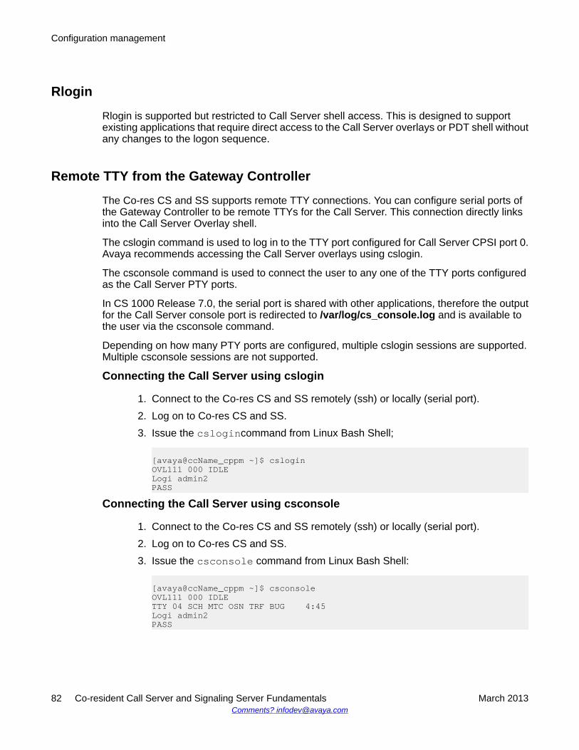
Rlogin
Rlogin is supported but restricted to Call Server shell access. This is designed to supportexisting applications that require direct access to the Call Server overlays or PDT shell withoutany changes to the logon sequence.
Remote TTY from the Gateway Controller
The Co-res CS and SS supports remote TTY connections. You can configure serial ports ofthe Gateway Controller to be remote TTYs for the Call Server. This connection directly linksinto the Call Server Overlay shell.
The cslogin command is used to log in to the TTY port configured for Call Server CPSI port 0.Avaya recommends accessing the Call Server overlays using cslogin.
The csconsole command is used to connect the user to any one of the TTY ports configuredas the Call Server PTY ports.
In CS 1000 Release 7.0, the serial port is shared with other applications, therefore the outputfor the Call Server console port is redirected to /var/log/cs_console.log and is available tothe user via the csconsole command.
Depending on how many PTY ports are configured, multiple cslogin sessions are supported.Multiple csconsole sessions are not supported.
Connecting the Call Server using cslogin
1. Connect to the Co-res CS and SS remotely (ssh) or locally (serial port).2. Log on to Co-res CS and SS.3. Issue the cslogincommand from Linux Bash Shell;
[avaya@ccName_cppm ~]$ csloginOVL111 000 IDLELogi admin2PASS
Connecting the Call Server using csconsole
1. Connect to the Co-res CS and SS remotely (ssh) or locally (serial port).2. Log on to Co-res CS and SS.3. Issue the csconsole command from Linux Bash Shell:
[avaya@ccName_cppm ~]$ csconsoleOVL111 000 IDLETTY 04 SCH MTC OSN TRF BUG 4:45Logi admin2PASS
Configuration management
82 Co-resident Call Server and Signaling Server Fundamentals March 2013Comments? [email protected]
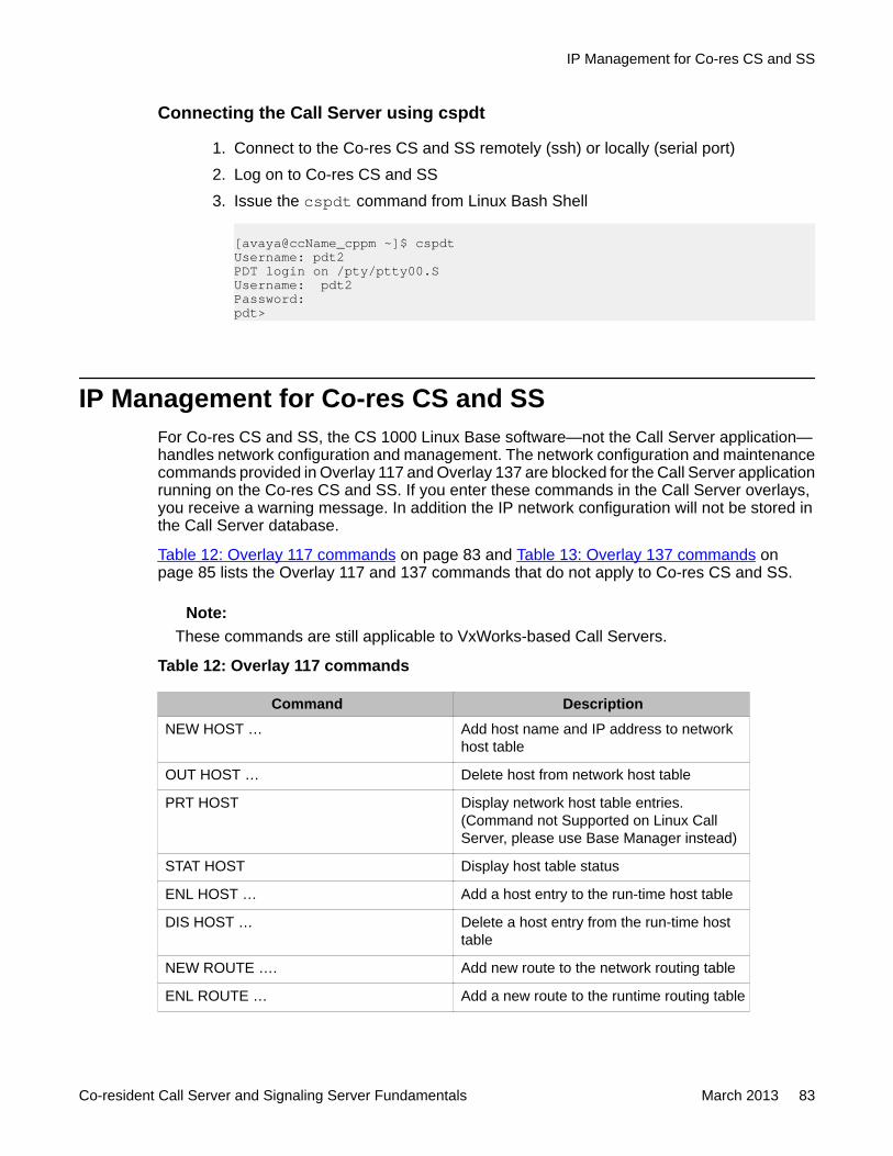
Connecting the Call Server using cspdt
1. Connect to the Co-res CS and SS remotely (ssh) or locally (serial port)2. Log on to Co-res CS and SS3. Issue the cspdt command from Linux Bash Shell
[avaya@ccName_cppm ~]$ cspdtUsername: pdt2PDT login on /pty/ptty00.SUsername: pdt2Password:pdt>
IP Management for Co-res CS and SSFor Co-res CS and SS, the CS 1000 Linux Base software—not the Call Server application—handles network configuration and management. The network configuration and maintenancecommands provided in Overlay 117 and Overlay 137 are blocked for the Call Server applicationrunning on the Co-res CS and SS. If you enter these commands in the Call Server overlays,you receive a warning message. In addition the IP network configuration will not be stored inthe Call Server database.
Table 12: Overlay 117 commands on page 83 and Table 13: Overlay 137 commands onpage 85 lists the Overlay 117 and 137 commands that do not apply to Co-res CS and SS.
Note:These commands are still applicable to VxWorks-based Call Servers.
Table 12: Overlay 117 commands
Command DescriptionNEW HOST … Add host name and IP address to network
host table
OUT HOST … Delete host from network host table
PRT HOST Display network host table entries.(Command not Supported on Linux CallServer, please use Base Manager instead)
STAT HOST Display host table status
ENL HOST … Add a host entry to the run-time host table
DIS HOST … Delete a host entry from the run-time hosttable
NEW ROUTE …. Add new route to the network routing table
ENL ROUTE … Add a new route to the runtime routing table
IP Management for Co-res CS and SS
Co-resident Call Server and Signaling Server Fundamentals March 2013 83
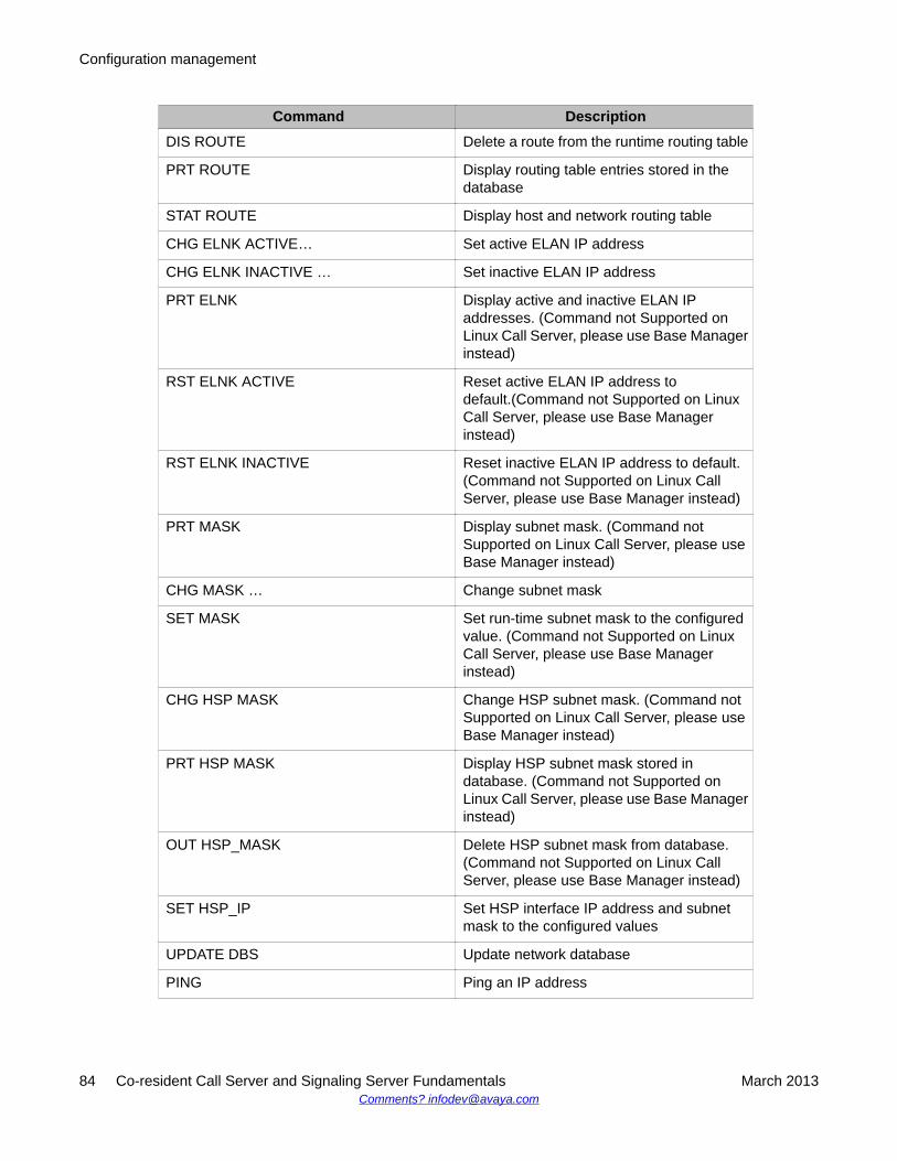
Command DescriptionDIS ROUTE Delete a route from the runtime routing table
PRT ROUTE Display routing table entries stored in thedatabase
STAT ROUTE Display host and network routing table
CHG ELNK ACTIVE… Set active ELAN IP address
CHG ELNK INACTIVE … Set inactive ELAN IP address
PRT ELNK Display active and inactive ELAN IPaddresses. (Command not Supported onLinux Call Server, please use Base Managerinstead)
RST ELNK ACTIVE Reset active ELAN IP address todefault.(Command not Supported on LinuxCall Server, please use Base Managerinstead)
RST ELNK INACTIVE Reset inactive ELAN IP address to default.(Command not Supported on Linux CallServer, please use Base Manager instead)
PRT MASK Display subnet mask. (Command notSupported on Linux Call Server, please useBase Manager instead)
CHG MASK … Change subnet mask
SET MASK Set run-time subnet mask to the configuredvalue. (Command not Supported on LinuxCall Server, please use Base Managerinstead)
CHG HSP MASK Change HSP subnet mask. (Command notSupported on Linux Call Server, please useBase Manager instead)
PRT HSP MASK Display HSP subnet mask stored indatabase. (Command not Supported onLinux Call Server, please use Base Managerinstead)
OUT HSP_MASK Delete HSP subnet mask from database.(Command not Supported on Linux CallServer, please use Base Manager instead)
SET HSP_IP Set HSP interface IP address and subnetmask to the configured values
UPDATE DBS Update network database
PING Ping an IP address
Configuration management
84 Co-resident Call Server and Signaling Server Fundamentals March 2013Comments? [email protected]
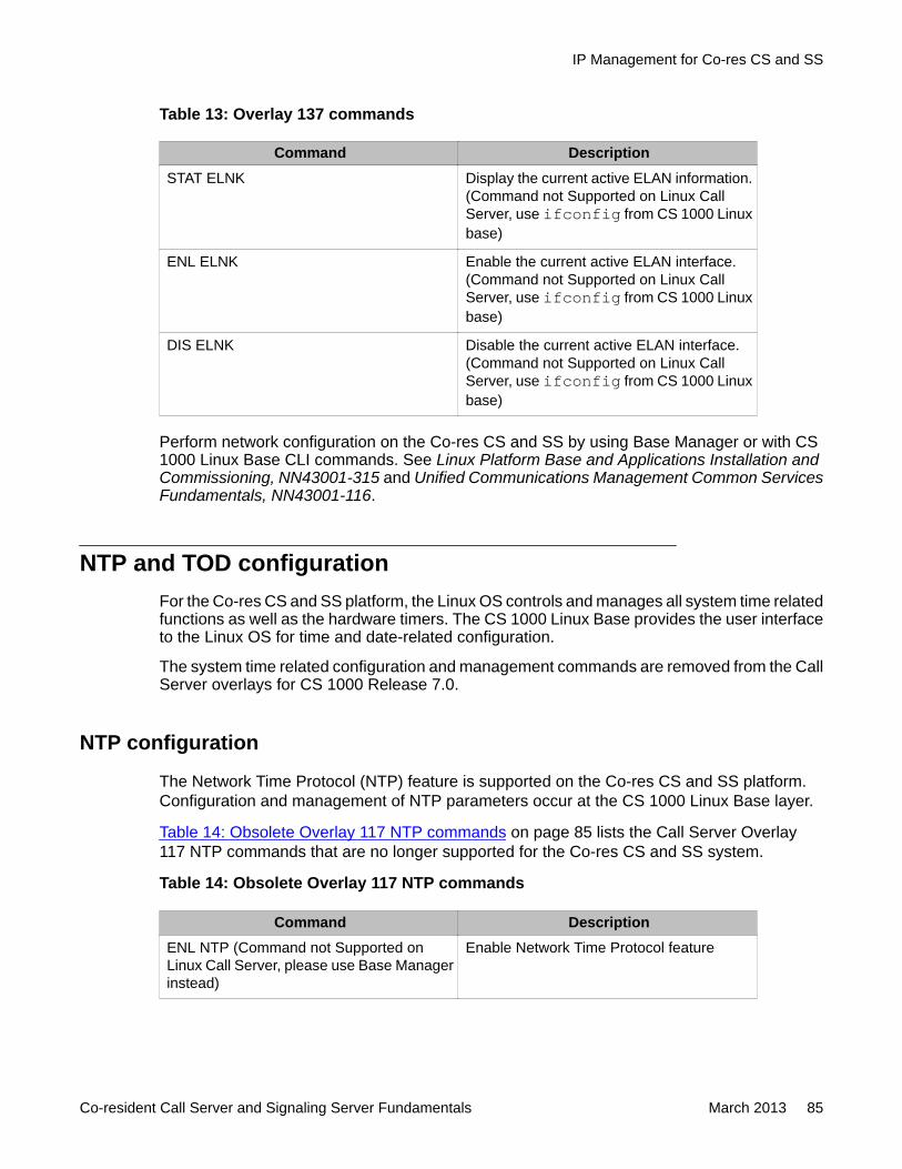
Table 13: Overlay 137 commands
Command DescriptionSTAT ELNK Display the current active ELAN information.
(Command not Supported on Linux CallServer, use ifconfig from CS 1000 Linuxbase)
ENL ELNK Enable the current active ELAN interface.(Command not Supported on Linux CallServer, use ifconfig from CS 1000 Linuxbase)
DIS ELNK Disable the current active ELAN interface.(Command not Supported on Linux CallServer, use ifconfig from CS 1000 Linuxbase)
Perform network configuration on the Co-res CS and SS by using Base Manager or with CS1000 Linux Base CLI commands. See Linux Platform Base and Applications Installation andCommissioning, NN43001-315 and Unified Communications Management Common ServicesFundamentals, NN43001-116.
NTP and TOD configurationFor the Co-res CS and SS platform, the Linux OS controls and manages all system time relatedfunctions as well as the hardware timers. The CS 1000 Linux Base provides the user interfaceto the Linux OS for time and date-related configuration.
The system time related configuration and management commands are removed from the CallServer overlays for CS 1000 Release 7.0.
NTP configuration
The Network Time Protocol (NTP) feature is supported on the Co-res CS and SS platform.Configuration and management of NTP parameters occur at the CS 1000 Linux Base layer.
Table 14: Obsolete Overlay 117 NTP commands on page 85 lists the Call Server Overlay117 NTP commands that are no longer supported for the Co-res CS and SS system.
Table 14: Obsolete Overlay 117 NTP commands
Command DescriptionENL NTP (Command not Supported onLinux Call Server, please use Base Managerinstead)
Enable Network Time Protocol feature
IP Management for Co-res CS and SS
Co-resident Call Server and Signaling Server Fundamentals March 2013 85
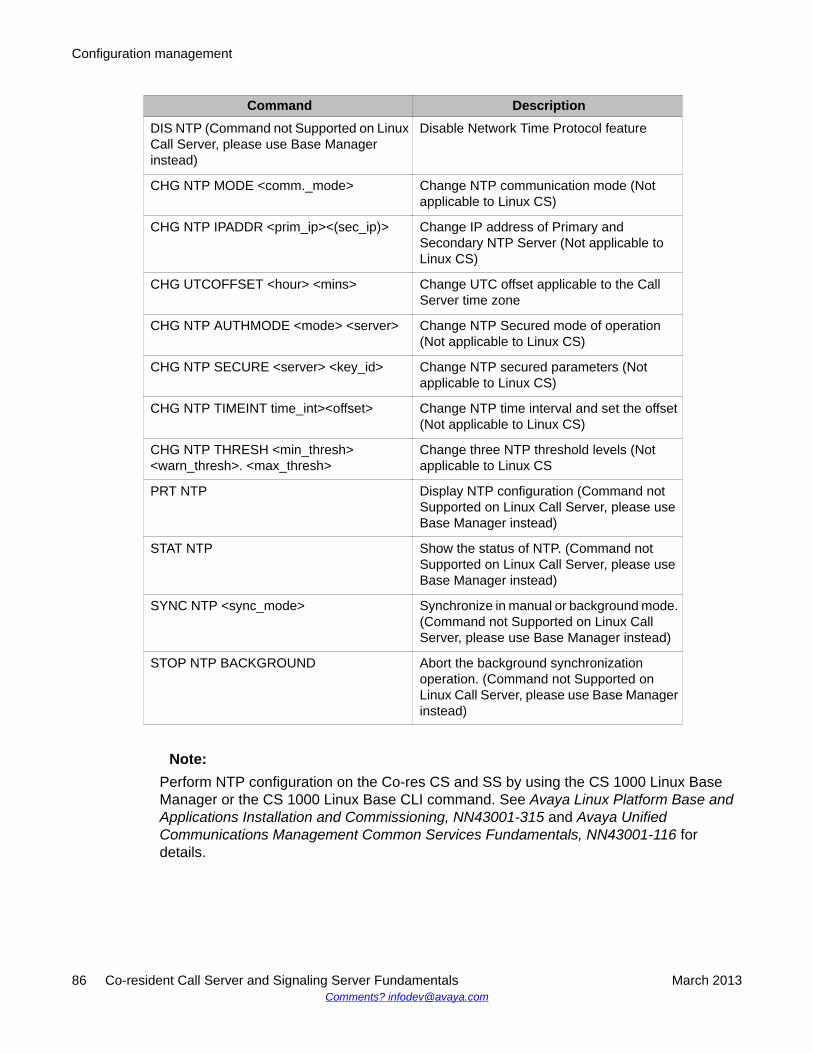
Command DescriptionDIS NTP (Command not Supported on LinuxCall Server, please use Base Managerinstead)
Disable Network Time Protocol feature
CHG NTP MODE <comm._mode> Change NTP communication mode (Notapplicable to Linux CS)
CHG NTP IPADDR <prim_ip><(sec_ip)> Change IP address of Primary andSecondary NTP Server (Not applicable toLinux CS)
CHG UTCOFFSET <hour> <mins> Change UTC offset applicable to the CallServer time zone
CHG NTP AUTHMODE <mode> <server> Change NTP Secured mode of operation(Not applicable to Linux CS)
CHG NTP SECURE <server> <key_id> Change NTP secured parameters (Notapplicable to Linux CS)
CHG NTP TIMEINT time_int><offset> Change NTP time interval and set the offset(Not applicable to Linux CS)
CHG NTP THRESH <min_thresh><warn_thresh>. <max_thresh>
Change three NTP threshold levels (Notapplicable to Linux CS
PRT NTP Display NTP configuration (Command notSupported on Linux Call Server, please useBase Manager instead)
STAT NTP Show the status of NTP. (Command notSupported on Linux Call Server, please useBase Manager instead)
SYNC NTP <sync_mode> Synchronize in manual or background mode.(Command not Supported on Linux CallServer, please use Base Manager instead)
STOP NTP BACKGROUND Abort the background synchronizationoperation. (Command not Supported onLinux Call Server, please use Base Managerinstead)
Note:Perform NTP configuration on the Co-res CS and SS by using the CS 1000 Linux BaseManager or the CS 1000 Linux Base CLI command. See Avaya Linux Platform Base andApplications Installation and Commissioning, NN43001-315 and Avaya UnifiedCommunications Management Common Services Fundamentals, NN43001-116 fordetails.
Configuration management
86 Co-resident Call Server and Signaling Server Fundamentals March 2013Comments? [email protected]
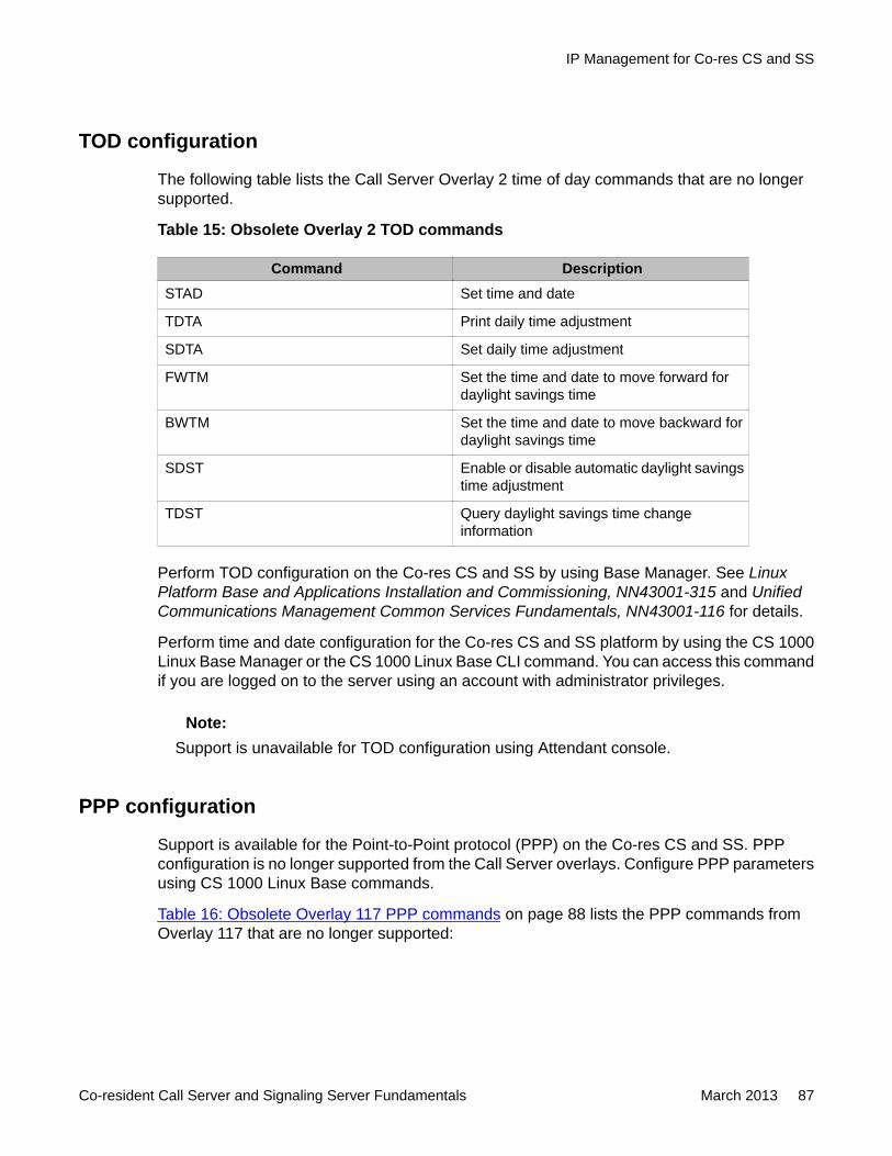
TOD configuration
The following table lists the Call Server Overlay 2 time of day commands that are no longersupported.
Table 15: Obsolete Overlay 2 TOD commands
Command DescriptionSTAD Set time and date
TDTA Print daily time adjustment
SDTA Set daily time adjustment
FWTM Set the time and date to move forward fordaylight savings time
BWTM Set the time and date to move backward fordaylight savings time
SDST Enable or disable automatic daylight savingstime adjustment
TDST Query daylight savings time changeinformation
Perform TOD configuration on the Co-res CS and SS by using Base Manager. See LinuxPlatform Base and Applications Installation and Commissioning, NN43001-315 and UnifiedCommunications Management Common Services Fundamentals, NN43001-116 for details.
Perform time and date configuration for the Co-res CS and SS platform by using the CS 1000Linux Base Manager or the CS 1000 Linux Base CLI command. You can access this commandif you are logged on to the server using an account with administrator privileges.
Note:Support is unavailable for TOD configuration using Attendant console.
PPP configuration
Support is available for the Point-to-Point protocol (PPP) on the Co-res CS and SS. PPPconfiguration is no longer supported from the Call Server overlays. Configure PPP parametersusing CS 1000 Linux Base commands.
Table 16: Obsolete Overlay 117 PPP commands on page 88 lists the PPP commands fromOverlay 117 that are no longer supported:
IP Management for Co-res CS and SS
Co-resident Call Server and Signaling Server Fundamentals March 2013 87
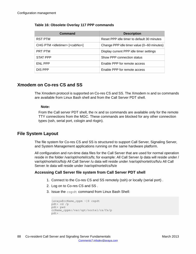
Table 16: Obsolete Overlay 117 PPP commands
Command DescriptionRST PTM Reset PPP idle timer to default 30 minutes
CHG PTM <idletimer> [<cabNo>] Change PPP idle timer value (0--60 minutes)
PRT PTM Display current PPP idle timer settings
STAT PPP Show PPP connection status
ENL PPP Enable PPP for remote access
DIS PPP Enable PPP for remote access
Xmodem on Co-res CS and SS
The Xmodem protocol is supported on Co-res CS and SS. The Xmodem rx and sx commandsare available from Linux Bash shell and from the Call Server PDT shell.
Note:From the Call server PDT shell, the rx and sx commands are available only for the remoteTTY connections from the MGC. These commands are blocked for any other connectiontypes (ssh, serial port, cslogin and rlogin).
File System Layout
The file system for Co-res CS and SS is structured to support Call Server, Signaling Server,and System Management applications running on the same hardware platform.
All configuration and run-time data files for the Call Server that are used for normal operationreside in the folder /var/opt/nortel/cs/fs; for example: All Call Server /p data will reside under /var/opt/nortel/cs/fs/p All Call Server /u data will reside under /var/opt/nortel/cs/fs/u All CallServer /e data will reside under /var/opt/nortel/cs/fs/e
Accessing Call Server file system from Call Server PDT shell
1. Connect to the Co-res CS and SS remotely (ssh) or locally (serial port) .2. Log on to Co-res CS and SS .3. Issue the cspdt command from Linux Bash Shell:
[avaya@ccName_cppm ~]$ cspdtpdt> cd /ppdt> pwdccName_cppm:/var/opt/nortel/cs/fs/ppdt>
Configuration management
88 Co-resident Call Server and Signaling Server Fundamentals March 2013Comments? [email protected]
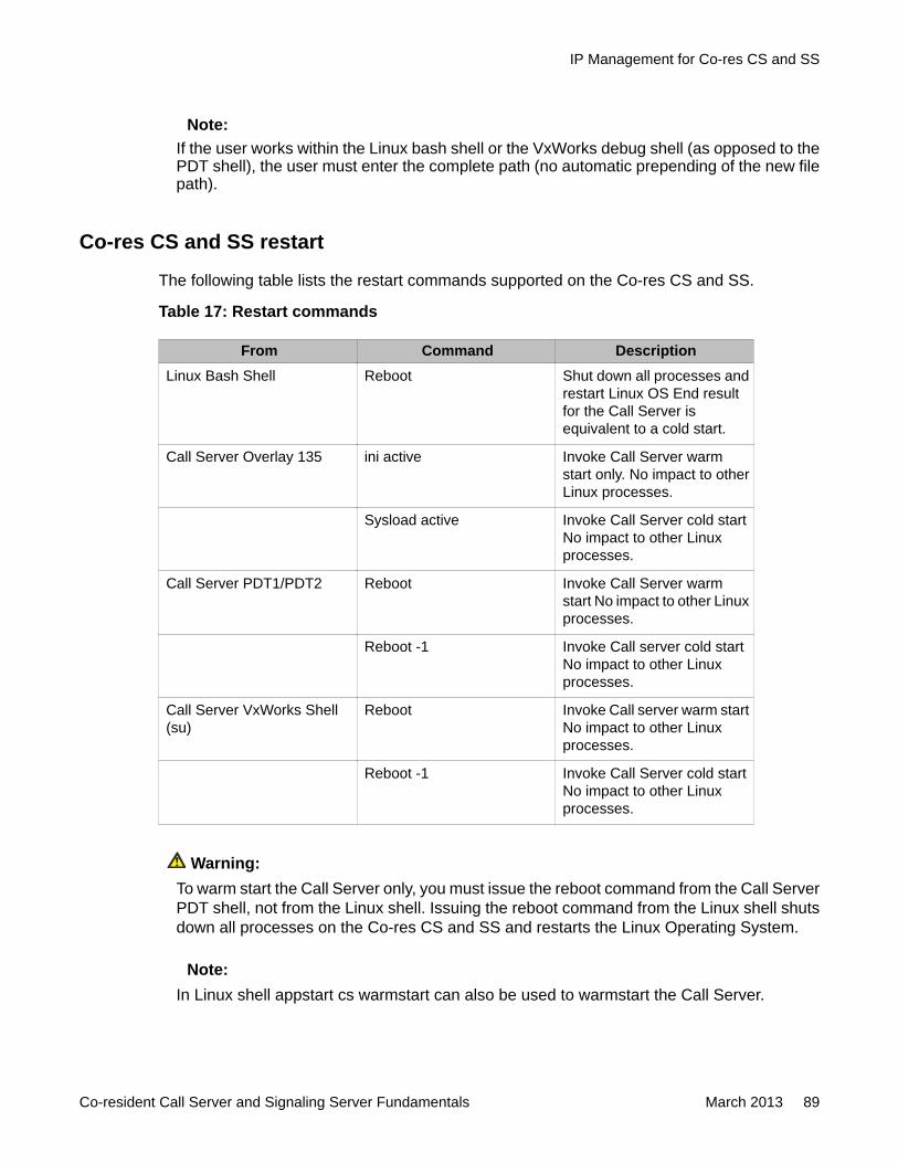
Note:If the user works within the Linux bash shell or the VxWorks debug shell (as opposed to thePDT shell), the user must enter the complete path (no automatic prepending of the new filepath).
Co-res CS and SS restart
The following table lists the restart commands supported on the Co-res CS and SS.
Table 17: Restart commands
From Command DescriptionLinux Bash Shell Reboot Shut down all processes and
restart Linux OS End resultfor the Call Server isequivalent to a cold start.
Call Server Overlay 135 ini active Invoke Call Server warmstart only. No impact to otherLinux processes.
Sysload active Invoke Call Server cold startNo impact to other Linuxprocesses.
Call Server PDT1/PDT2 Reboot Invoke Call Server warmstart No impact to other Linuxprocesses.
Reboot -1 Invoke Call server cold startNo impact to other Linuxprocesses.
Call Server VxWorks Shell(su)
Reboot Invoke Call server warm startNo impact to other Linuxprocesses.
Reboot -1 Invoke Call Server cold startNo impact to other Linuxprocesses.
Warning:To warm start the Call Server only, you must issue the reboot command from the Call ServerPDT shell, not from the Linux shell. Issuing the reboot command from the Linux shell shutsdown all processes on the Co-res CS and SS and restarts the Linux Operating System.
Note:In Linux shell appstart cs warmstart can also be used to warmstart the Call Server.
IP Management for Co-res CS and SS
Co-resident Call Server and Signaling Server Fundamentals March 2013 89
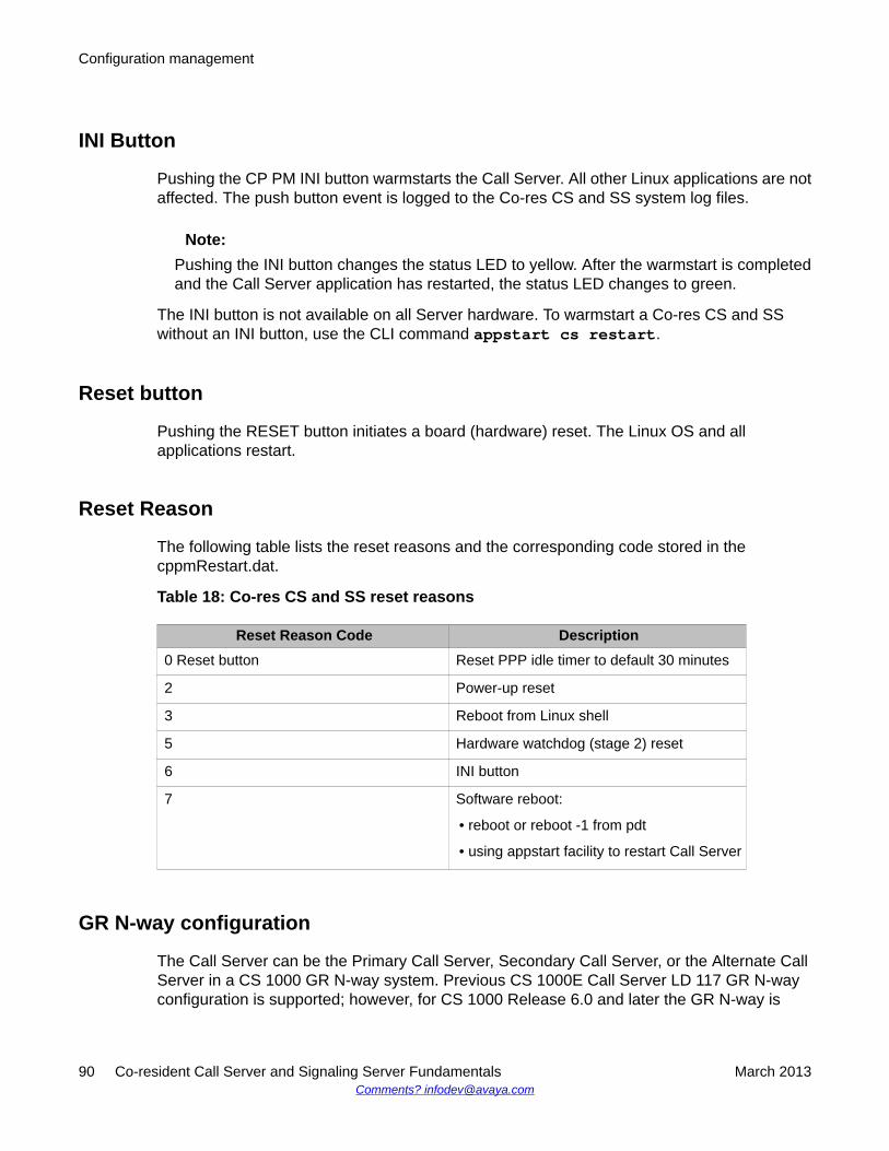
INI Button
Pushing the CP PM INI button warmstarts the Call Server. All other Linux applications are notaffected. The push button event is logged to the Co-res CS and SS system log files.
Note:Pushing the INI button changes the status LED to yellow. After the warmstart is completedand the Call Server application has restarted, the status LED changes to green.
The INI button is not available on all Server hardware. To warmstart a Co-res CS and SSwithout an INI button, use the CLI command appstart cs restart.
Reset button
Pushing the RESET button initiates a board (hardware) reset. The Linux OS and allapplications restart.
Reset Reason
The following table lists the reset reasons and the corresponding code stored in thecppmRestart.dat.
Table 18: Co-res CS and SS reset reasons
Reset Reason Code Description0 Reset button Reset PPP idle timer to default 30 minutes
2 Power-up reset
3 Reboot from Linux shell
5 Hardware watchdog (stage 2) reset
6 INI button
7 Software reboot:
• reboot or reboot -1 from pdt
• using appstart facility to restart Call Server
GR N-way configuration
The Call Server can be the Primary Call Server, Secondary Call Server, or the Alternate CallServer in a CS 1000 GR N-way system. Previous CS 1000E Call Server LD 117 GR N-wayconfiguration is supported; however, for CS 1000 Release 6.0 and later the GR N-way is
Configuration management
90 Co-resident Call Server and Signaling Server Fundamentals March 2013Comments? [email protected]
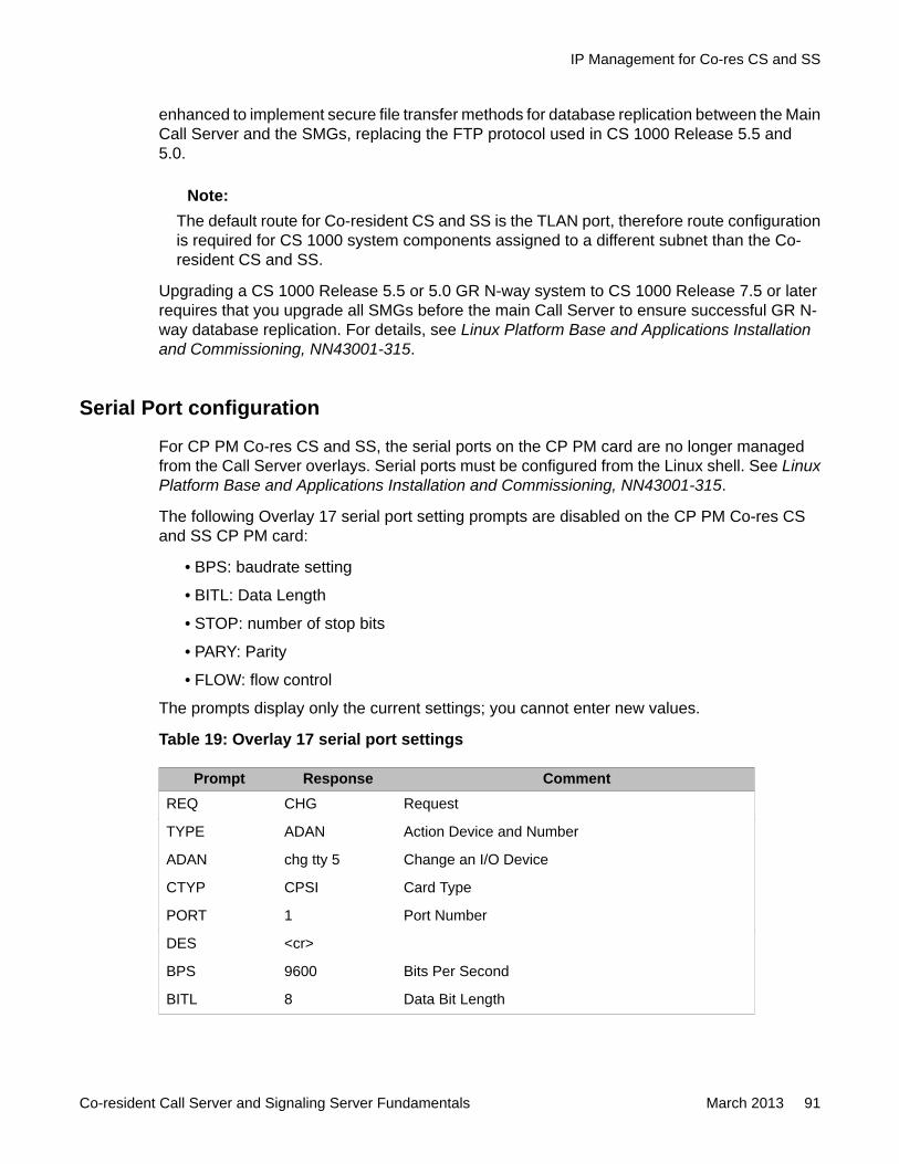
enhanced to implement secure file transfer methods for database replication between the MainCall Server and the SMGs, replacing the FTP protocol used in CS 1000 Release 5.5 and5.0.
Note:The default route for Co-resident CS and SS is the TLAN port, therefore route configurationis required for CS 1000 system components assigned to a different subnet than the Co-resident CS and SS.
Upgrading a CS 1000 Release 5.5 or 5.0 GR N-way system to CS 1000 Release 7.5 or laterrequires that you upgrade all SMGs before the main Call Server to ensure successful GR N-way database replication. For details, see Linux Platform Base and Applications Installationand Commissioning, NN43001-315.
Serial Port configuration
For CP PM Co-res CS and SS, the serial ports on the CP PM card are no longer managedfrom the Call Server overlays. Serial ports must be configured from the Linux shell. See LinuxPlatform Base and Applications Installation and Commissioning, NN43001-315.
The following Overlay 17 serial port setting prompts are disabled on the CP PM Co-res CSand SS CP PM card:
• BPS: baudrate setting
• BITL: Data Length
• STOP: number of stop bits
• PARY: Parity
• FLOW: flow control
The prompts display only the current settings; you cannot enter new values.
Table 19: Overlay 17 serial port settings
Prompt Response CommentREQ CHG Request
TYPE ADAN Action Device and Number
ADAN chg tty 5 Change an I/O Device
CTYP CPSI Card Type
PORT 1 Port Number
DES <cr>
BPS 9600 Bits Per Second
BITL 8 Data Bit Length
IP Management for Co-res CS and SS
Co-resident Call Server and Signaling Server Fundamentals March 2013 91
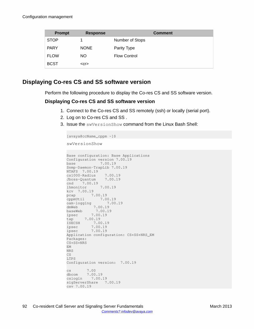
Prompt Response CommentSTOP 1 Number of Stops
PARY NONE Parity Type
FLOW NO Flow Control
BCST <cr>
Displaying Co-res CS and SS software version
Perform the following procedure to display the Co-res CS and SS software version.
Displaying Co-res CS and SS software version
1. Connect to the Co-res CS and SS remotely (ssh) or locally (serial port).2. Log on to Co-res CS and SS .3. Issue the swVersionShow command from the Linux Bash Shell:
[avaya@ccName_cppm ~]$swVersionShow
Base configuration: Base ApplicationsConfiguration version 7.00.19base 7.00.19Snmp-Daemon-TrapLib 7.00.19NTAFS 7.00.19cs1000-Radius 7.00.19Jboss-Quantum 7.00.19cnd 7.00.19lhmonitor 7.00.19kcv 7.00.19pcap 7.00.19cppmUtil 7.00.19oam-logging 7.00.19dmWeb 7.00.19baseWeb 7.00.19ipsec 7.00.19tap 7.00.19ISECSH 7.00.19ipsec 7.00.19ipsec 7.00.19Application configuration: CS+SS+NRS_EMPackages:CS+SS+NRSEMNRSCSLTPSConfiguration version: 7.00.19
cs 7.00dbcom 7.00.19cslogin 7.00.19sigServerShare 7.00.19csv 7.00.19
Configuration management
92 Co-resident Call Server and Signaling Server Fundamentals March 2013Comments? [email protected]
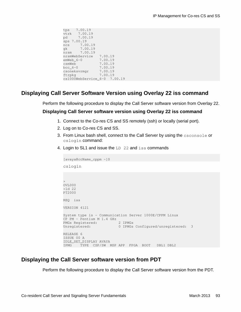
tps 7.00.19vtrk 7.00.19pd 7.00.19sps 7.00.19ncs 7.00.19gk 7.00.19nrsm 7.00.19nrsmWebService 7.00.19emWeb_6-0 7.00.19csmWeb 7.00.19bcc_6-0 7.00.19csoneksvrmgr 7.00.19ftrpkg 7.00.19cs1000WebService_6-0 7.00.19
Displaying Call Server Software Version using Overlay 22 iss command
Perform the following procedure to display the Call Server software version from Overlay 22.
Displaying Call Server software version using Overlay 22 iss command
1. Connect to the Co-res CS and SS remotely (ssh) or locally (serial port).2. Log on to Co-res CS and SS.3. From Linux bash shell, connect to the Call Server by using the csconsole or
cslogin command:
4. Login to SL1 and issue the LD 22 and iss commands
[avaya@ccName_cppm ~]$cslogin
>OVL000>ld 22PT2000
REQ iss
VERSION 4121
System type is - Communication Server 1000E/CPPM LinuxCP PM - Pentium M 1.4 GHzPMGs Registered: 2 IPMGsUnregistered: 0 IPMGs Configured/unregistered: 3
RELEASE 6ISSUE 00 AIDLE_SET_DISPLAY AVAYAIPMG TYPE CSP/SW MSP APP FPGA BOOT DBL1 DBL2
Displaying the Call Server software version from PDT
Perform the following procedure to display the Call Server software version from the PDT.
IP Management for Co-res CS and SS
Co-resident Call Server and Signaling Server Fundamentals March 2013 93
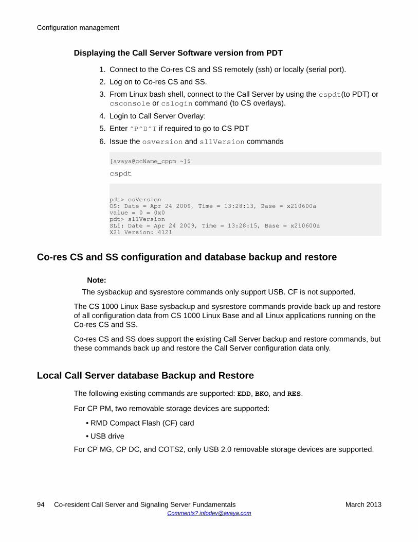
Displaying the Call Server Software version from PDT
1. Connect to the Co-res CS and SS remotely (ssh) or locally (serial port).2. Log on to Co-res CS and SS.3. From Linux bash shell, connect to the Call Server by using the cspdt(to PDT) or
csconsole or cslogin command (to CS overlays).
4. Login to Call Server Overlay:5. Enter ^P^D^T if required to go to CS PDT
6. Issue the osversion and sl1Version commands
[avaya@ccName_cppm ~]$cspdt
pdt> osVersionOS: Date = Apr 24 2009, Time = 13:28:13, Base = x210600avalue = 0 = 0x0pdt> sl1VersionSL1: Date = Apr 24 2009, Time = 13:28:15, Base = x210600aX21 Version: 4121
Co-res CS and SS configuration and database backup and restore
Note:The sysbackup and sysrestore commands only support USB. CF is not supported.
The CS 1000 Linux Base sysbackup and sysrestore commands provide back up and restoreof all configuration data from CS 1000 Linux Base and all Linux applications running on theCo-res CS and SS.
Co-res CS and SS does support the existing Call Server backup and restore commands, butthese commands back up and restore the Call Server configuration data only.
Local Call Server database Backup and Restore
The following existing commands are supported: EDD, BKO, and RES.
For CP PM, two removable storage devices are supported:
• RMD Compact Flash (CF) card
• USB drive
For CP MG, CP DC, and COTS2, only USB 2.0 removable storage devices are supported.
Configuration management
94 Co-resident Call Server and Signaling Server Fundamentals March 2013Comments? [email protected]
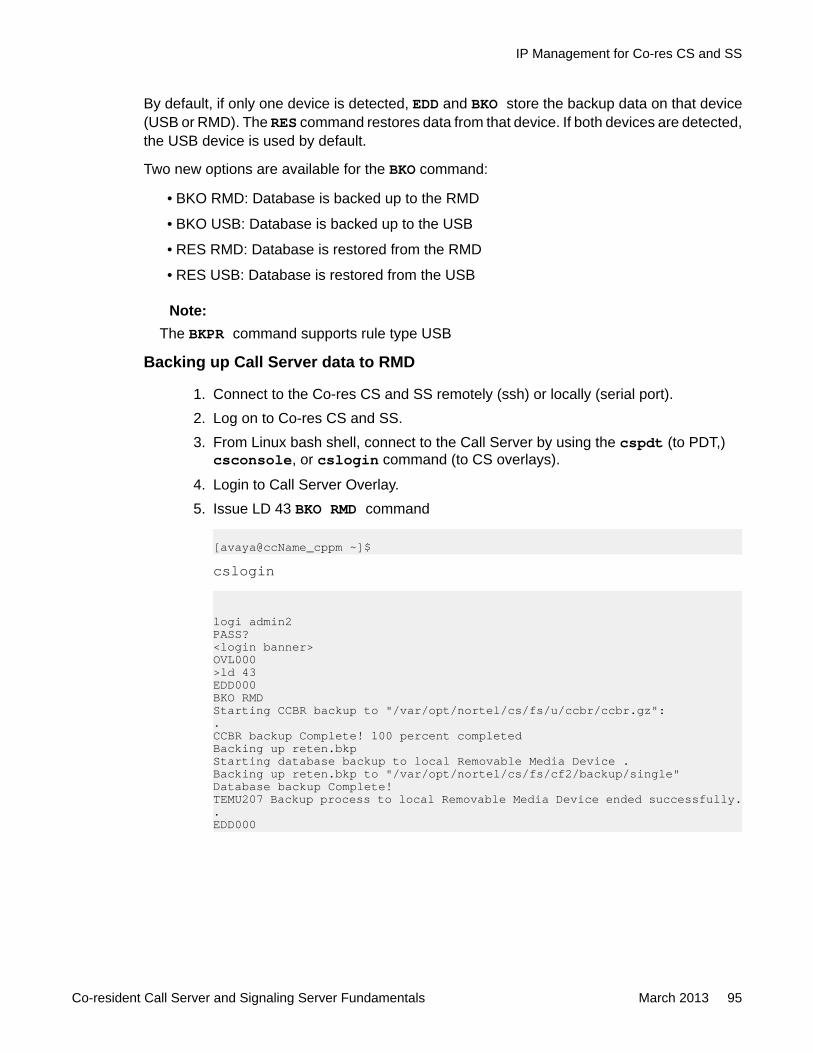
By default, if only one device is detected, EDD and BKO store the backup data on that device(USB or RMD). The RES command restores data from that device. If both devices are detected,the USB device is used by default.
Two new options are available for the BKO command:
• BKO RMD: Database is backed up to the RMD
• BKO USB: Database is backed up to the USB
• RES RMD: Database is restored from the RMD
• RES USB: Database is restored from the USB
Note:The BKPR command supports rule type USB
Backing up Call Server data to RMD
1. Connect to the Co-res CS and SS remotely (ssh) or locally (serial port).2. Log on to Co-res CS and SS.3. From Linux bash shell, connect to the Call Server by using the cspdt (to PDT,)
csconsole, or cslogin command (to CS overlays).
4. Login to Call Server Overlay.5. Issue LD 43 BKO RMD command
[avaya@ccName_cppm ~]$cslogin
logi admin2PASS?<login banner>OVL000>ld 43EDD000BKO RMDStarting CCBR backup to "/var/opt/nortel/cs/fs/u/ccbr/ccbr.gz":.CCBR backup Complete! 100 percent completedBacking up reten.bkpStarting database backup to local Removable Media Device .Backing up reten.bkp to "/var/opt/nortel/cs/fs/cf2/backup/single"Database backup Complete!TEMU207 Backup process to local Removable Media Device ended successfully..EDD000
IP Management for Co-res CS and SS
Co-resident Call Server and Signaling Server Fundamentals March 2013 95
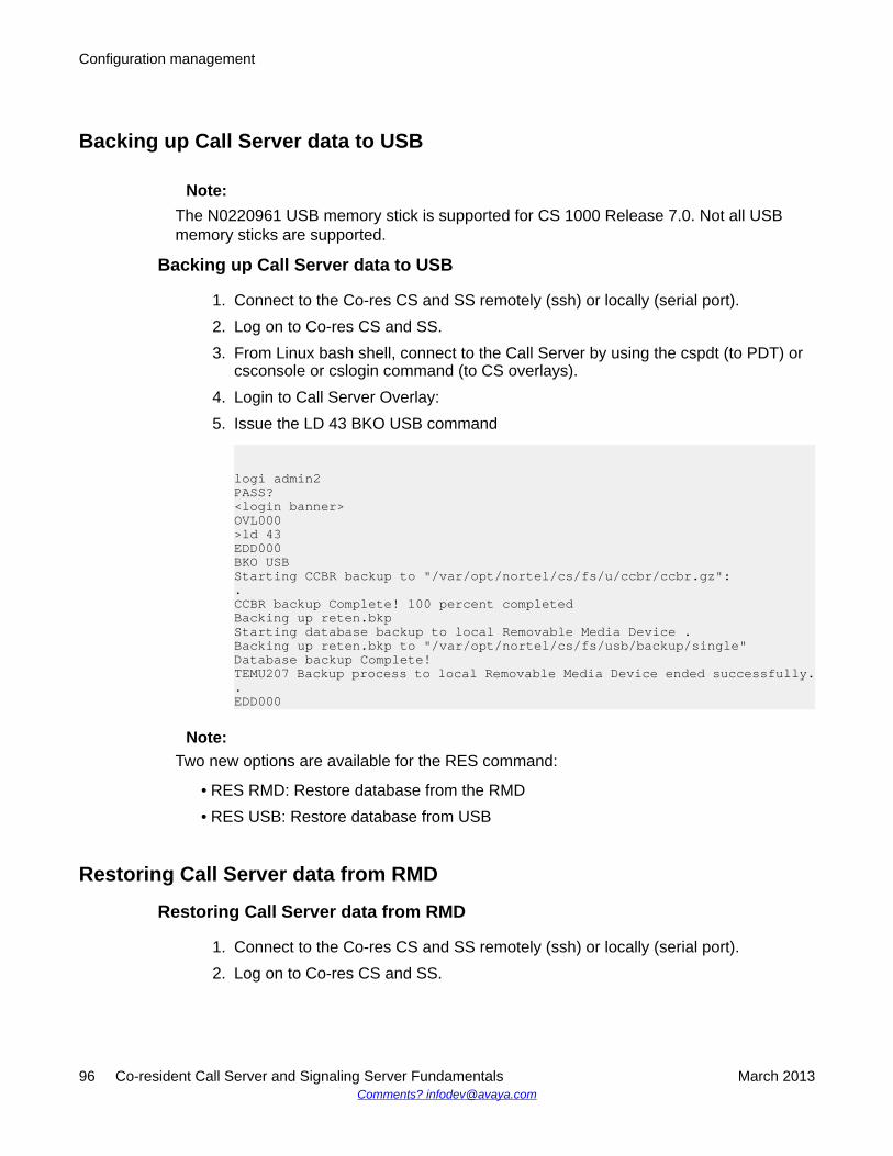
Backing up Call Server data to USB
Note:The N0220961 USB memory stick is supported for CS 1000 Release 7.0. Not all USBmemory sticks are supported.
Backing up Call Server data to USB
1. Connect to the Co-res CS and SS remotely (ssh) or locally (serial port).2. Log on to Co-res CS and SS.3. From Linux bash shell, connect to the Call Server by using the cspdt (to PDT) or
csconsole or cslogin command (to CS overlays).4. Login to Call Server Overlay:5. Issue the LD 43 BKO USB command
logi admin2PASS?<login banner>OVL000>ld 43EDD000BKO USBStarting CCBR backup to "/var/opt/nortel/cs/fs/u/ccbr/ccbr.gz":.CCBR backup Complete! 100 percent completedBacking up reten.bkpStarting database backup to local Removable Media Device .Backing up reten.bkp to "/var/opt/nortel/cs/fs/usb/backup/single"Database backup Complete!TEMU207 Backup process to local Removable Media Device ended successfully..EDD000
Note:Two new options are available for the RES command:
• RES RMD: Restore database from the RMD• RES USB: Restore database from USB
Restoring Call Server data from RMD
Restoring Call Server data from RMD
1. Connect to the Co-res CS and SS remotely (ssh) or locally (serial port).2. Log on to Co-res CS and SS.
Configuration management
96 Co-resident Call Server and Signaling Server Fundamentals March 2013Comments? [email protected]
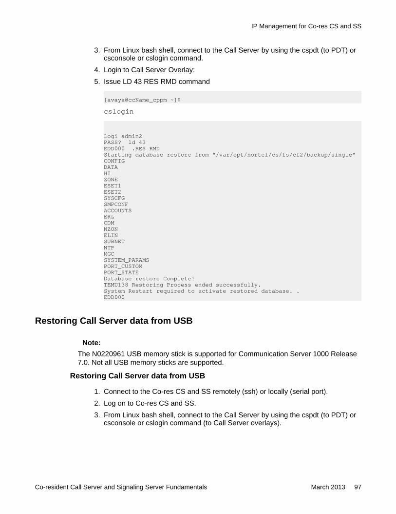
3. From Linux bash shell, connect to the Call Server by using the cspdt (to PDT) orcsconsole or cslogin command.
4. Login to Call Server Overlay:5. Issue LD 43 RES RMD command
[avaya@ccName_cppm ~]$cslogin
Logi admin2PASS? ld 43EDD000 .RES RMDStarting database restore from "/var/opt/nortel/cs/fs/cf2/backup/single"CONFIGDATAHIZONEESET1ESET2SYSCFGSMPCONFACCOUNTSERLCDMNZONELINSUBNETNTPMGCSYSTEM_PARAMSPORT_CUSTOMPORT_STATEDatabase restore Complete!TEMU138 Restoring Process ended successfully.System Restart required to activate restored database. .EDD000
Restoring Call Server data from USB
Note:The N0220961 USB memory stick is supported for Communication Server 1000 Release7.0. Not all USB memory sticks are supported.
Restoring Call Server data from USB
1. Connect to the Co-res CS and SS remotely (ssh) or locally (serial port).2. Log on to Co-res CS and SS.3. From Linux bash shell, connect to the Call Server by using the cspdt (to PDT) or
csconsole or cslogin command (to Call Server overlays).
IP Management for Co-res CS and SS
Co-resident Call Server and Signaling Server Fundamentals March 2013 97
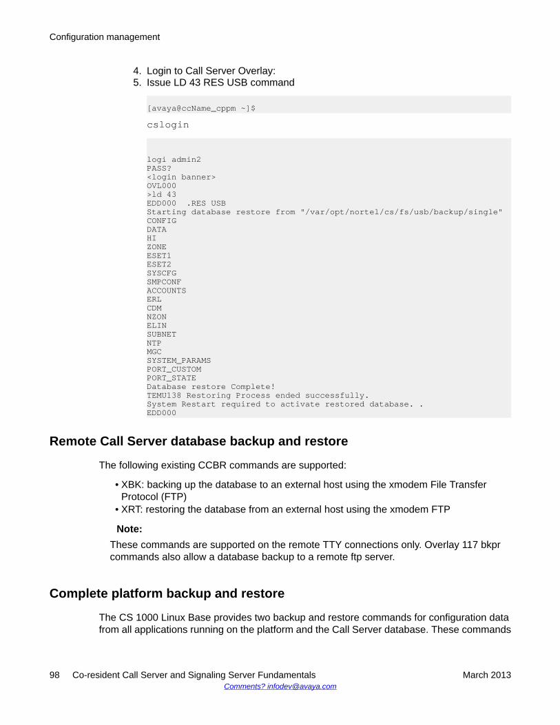
4. Login to Call Server Overlay:5. Issue LD 43 RES USB command
[avaya@ccName_cppm ~]$cslogin
logi admin2PASS?<login banner>OVL000>ld 43EDD000 .RES USBStarting database restore from "/var/opt/nortel/cs/fs/usb/backup/single"CONFIGDATAHIZONEESET1ESET2SYSCFGSMPCONFACCOUNTSERLCDMNZONELINSUBNETNTPMGCSYSTEM_PARAMSPORT_CUSTOMPORT_STATEDatabase restore Complete!TEMU138 Restoring Process ended successfully.System Restart required to activate restored database. .EDD000
Remote Call Server database backup and restore
The following existing CCBR commands are supported:
• XBK: backing up the database to an external host using the xmodem File TransferProtocol (FTP)
• XRT: restoring the database from an external host using the xmodem FTP
Note:These commands are supported on the remote TTY connections only. Overlay 117 bkprcommands also allow a database backup to a remote ftp server.
Complete platform backup and restore
The CS 1000 Linux Base provides two backup and restore commands for configuration datafrom all applications running on the platform and the Call Server database. These commands
Configuration management
98 Co-resident Call Server and Signaling Server Fundamentals March 2013Comments? [email protected]
are sysbackup and sysrestore. For details, see Linux Platform Base and ApplicationsInstallation and Commissioning, NN43001-315.
Note:Avaya recommends performing a data dump (EDD command) before executing thesysbackup command.
Call Server backup using Overlay 117 backup rules
In previous releases, the bkpr commands in Overlay 117 allowed users to configure a backuprule for backing up the Call Server database to a Secondary Call Server, the FMD, an RMD oran external remote FTP server. In addition to these targets, Co-res CS and SS supportsbacking up to a USB device as follows:
• new bkpr <ruleNumber> <ruleType> [N of Version] [Name]
• chg bkpr <ruleNumber> <ruleType> [N of Version] [Name]
where ruleType = <SCS | FTP | FMD |RMD | USB>
Media Gateway Centralized Software Upgrade
The Co-res CS and SS supports the existing Centralized Media Gateway software upgradefeature for upgrading the loadware on the Gateway Controller. The option to select thesequential or simultaneous upgrade method is no longer available during the Co-res CS andSS installation. The default setting for Centralized Software Upgrade is enabled and sequentialupon completion of the Co-res CS and SS system installation.
You can use the existing Overlay 143 UPGMG command to disable the Centralize SoftwareUpgrade feature. Use the same command to select the sequential or simultaneous upgradeoptions.
Note:If you add additional Media Gateways to the system after you enable the CentralizedSoftware Upgrade feature, the Co-res CS and SS automatically downloads the currentGateway Controller loadware to the newly added Media Gateways.
Note:The Centralized Software Upgrade settings are not backed up during Call Server Overlay43 EDD or CS 1000 Linux Base sysbackup. These settings must be re-entered using theOverlay 143 UPGMG command after a Co-res CS and SS installation or upgrade.
IP Management for Co-res CS and SS
Co-resident Call Server and Signaling Server Fundamentals March 2013 99
Server card location (loop and shelf) configuration
In order for the Co-res CS and SS to respond correctly to the Inventory and STAT CPUcommands in overlays 117 and 137 respectively, the Server card location information must beconfigured correctly.
On the Co-res CS and SS, the Server card location configuration can only be performed usingthe Overlay 117 CHG LCL commands. Unlike a VxWorks-based Call Server, the Co-res CSand SS does not support configuring the loop, shelf and side settings during the installprocess.
Configuration files
The network database file (inet.db) is not used in the Co-res CS and SS and is not backed upas part of the Call Server database. You must use the CS 1000 Linux Base sysbackup andsysrestore commands to back up the network configuration information.
Security configuration
UCM configurationIP Security configuration is no longer supported for the Co-res CS and SS Call Server. Instead,IP Security parameters must be configured from Avaya Unified Communications Management(UCM). See Unified Communications Management Common Services Fundamentals,NN43001-116 for details.
The following table lists the ISSS commands from LD 117 not supported on the CP PM Co-res CS and SS Call Server.
Table 20: LD 117: IPSSS commands not supported on the CP PM Co-res CS and SS CallServer
Command DescriptionCHG ISEC Change ISEC pre-shared key or security
level (ISEC--Intra System SignalingSecurity)
COMMIT ISEC Commit for ISEC profile changes
CONFIRM ISEC Used to confirm PSK between Active CallServer and other elements
Configuration management
100 Co-resident Call Server and Signaling Server Fundamentals March 2013Comments? [email protected]
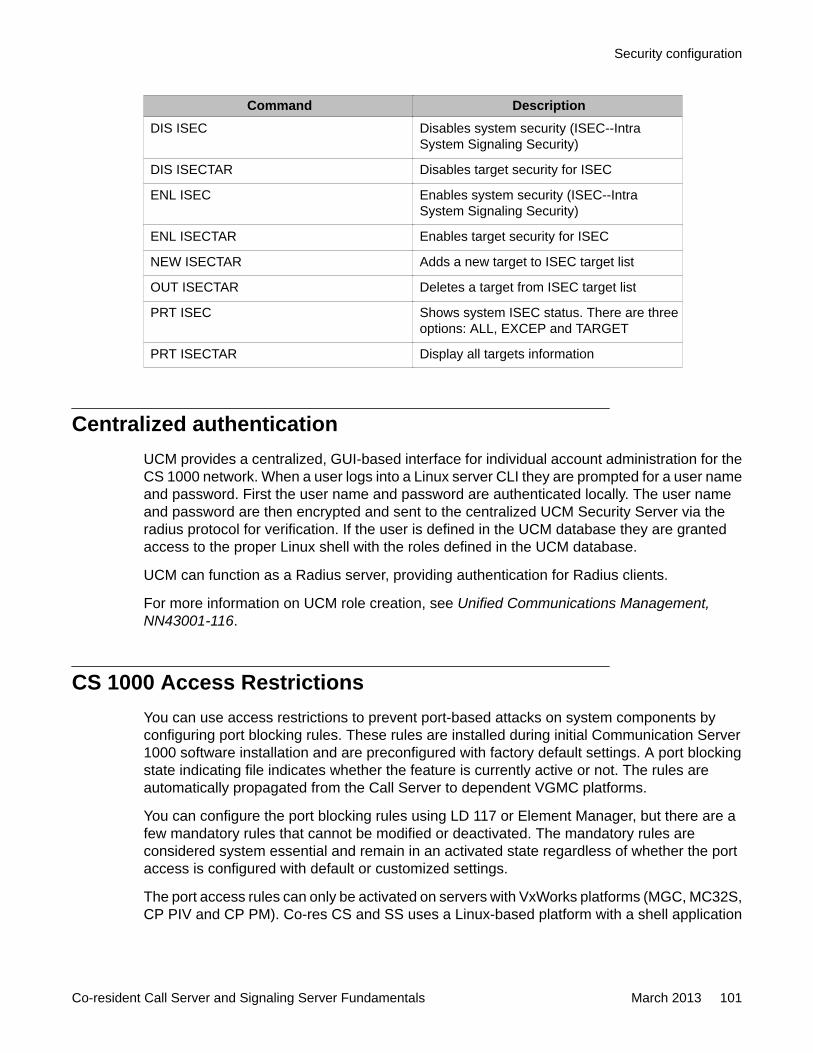
Command DescriptionDIS ISEC Disables system security (ISEC--Intra
System Signaling Security)
DIS ISECTAR Disables target security for ISEC
ENL ISEC Enables system security (ISEC--IntraSystem Signaling Security)
ENL ISECTAR Enables target security for ISEC
NEW ISECTAR Adds a new target to ISEC target list
OUT ISECTAR Deletes a target from ISEC target list
PRT ISEC Shows system ISEC status. There are threeoptions: ALL, EXCEP and TARGET
PRT ISECTAR Display all targets information
Centralized authenticationUCM provides a centralized, GUI-based interface for individual account administration for theCS 1000 network. When a user logs into a Linux server CLI they are prompted for a user nameand password. First the user name and password are authenticated locally. The user nameand password are then encrypted and sent to the centralized UCM Security Server via theradius protocol for verification. If the user is defined in the UCM database they are grantedaccess to the proper Linux shell with the roles defined in the UCM database.
UCM can function as a Radius server, providing authentication for Radius clients.
For more information on UCM role creation, see Unified Communications Management,NN43001-116.
CS 1000 Access RestrictionsYou can use access restrictions to prevent port-based attacks on system components byconfiguring port blocking rules. These rules are installed during initial Communication Server1000 software installation and are preconfigured with factory default settings. A port blockingstate indicating file indicates whether the feature is currently active or not. The rules areautomatically propagated from the Call Server to dependent VGMC platforms.
You can configure the port blocking rules using LD 117 or Element Manager, but there are afew mandatory rules that cannot be modified or deactivated. The mandatory rules areconsidered system essential and remain in an activated state regardless of whether the portaccess is configured with default or customized settings.
The port access rules can only be activated on servers with VxWorks platforms (MGC, MC32S,CP PIV and CP PM). Co-res CS and SS uses a Linux-based platform with a shell application
Security configuration
Co-resident Call Server and Signaling Server Fundamentals March 2013 101
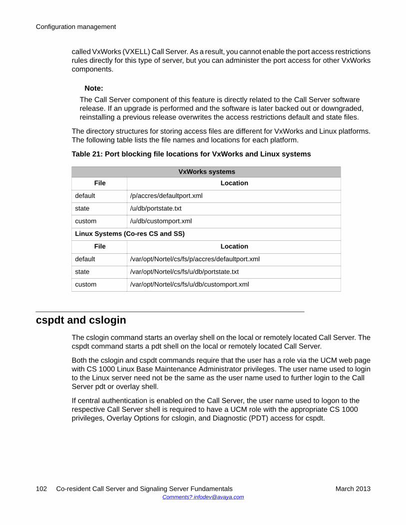
called VxWorks (VXELL) Call Server. As a result, you cannot enable the port access restrictionsrules directly for this type of server, but you can administer the port access for other VxWorkscomponents.
Note:The Call Server component of this feature is directly related to the Call Server softwarerelease. If an upgrade is performed and the software is later backed out or downgraded,reinstalling a previous release overwrites the access restrictions default and state files.
The directory structures for storing access files are different for VxWorks and Linux platforms.The following table lists the file names and locations for each platform.
Table 21: Port blocking file locations for VxWorks and Linux systems
VxWorks systemsFile Location
default /p/accres/defaultport.xml
state /u/db/portstate.txt
custom /u/db/customport.xml
Linux Systems (Co-res CS and SS)
File Location
default /var/opt/Nortel/cs/fs/p/accres/defaultport.xml
state /var/opt/Nortel/cs/fs/u/db/portstate.txt
custom /var/opt/Nortel/cs/fs/u/db/customport.xml
cspdt and csloginThe cslogin command starts an overlay shell on the local or remotely located Call Server. Thecspdt command starts a pdt shell on the local or remotely located Call Server.
Both the cslogin and cspdt commands require that the user has a role via the UCM web pagewith CS 1000 Linux Base Maintenance Administrator privileges. The user name used to loginto the Linux server need not be the same as the user name used to further login to the CallServer pdt or overlay shell.
If central authentication is enabled on the Call Server, the user name used to logon to therespective Call Server shell is required to have a UCM role with the appropriate CS 1000privileges, Overlay Options for cslogin, and Diagnostic (PDT) access for cspdt.
Configuration management
102 Co-resident Call Server and Signaling Server Fundamentals March 2013Comments? [email protected]
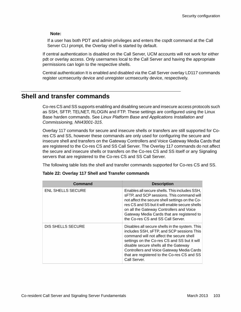
Note:If a user has both PDT and admin privileges and enters the cspdt command at the CallServer CLI prompt, the Overlay shell is started by default.
If central authentication is disabled on the Call Server, UCM accounts will not work for eitherpdt or overlay access. Only usernames local to the Call Server and having the appropriatepermissions can login to the respective shells.
Central authentication It is enabled and disabled via the Call Server overlay LD117 commandsregister ucmsecurity device and unregister ucmsecurity device, respectively.
Shell and transfer commandsCo-res CS and SS supports enabling and disabling secure and insecure access protocols suchas SSH, SFTP, TELNET, RLOGIN and FTP. These settings are configured using the LinuxBase harden commands. See Linux Platform Base and Applications Installation andCommissioning, NN43001-315.
Overlay 117 commands for secure and insecure shells or transfers are still supported for Co-res CS and SS, however these commands are only used for configuring the secure andinsecure shell and transfers on the Gateway Controllers and Voice Gateway Media Cards thatare registered to the Co-res CS and SS Call Server. The Overlay 117 commands do not affectthe secure and insecure shells or transfers on the Co-res CS and SS itself or any Signalingservers that are registered to the Co-res CS and SS Call Server.
The following table lists the shell and transfer commands supported for Co-res CS and SS.
Table 22: Overlay 117 Shell and Transfer commands
Command DescriptionENL SHELLS SECURE Enables all secure shells. This includes SSH,
sFTP, and SCP sessions. This command willnot affect the secure shell settings on the Co-res CS and SS but it will enable secure shellson all the Gateway Controllers and VoiceGateway Media Cards that are registered tothe Co-res CS and SS Call Server.
DIS SHELLS SECURE Disables all secure shells in the system. Thisincludes SSH, sFTP, and SCP sessions Thiscommand will not affect the secure shellsettings on the Co-res CS and SS but it willdisable secure shells all the GatewayControllers and Voice Gateway Media Cardsthat are registered to the Co-res CS and SSCall Server.
Security configuration
Co-resident Call Server and Signaling Server Fundamentals March 2013 103
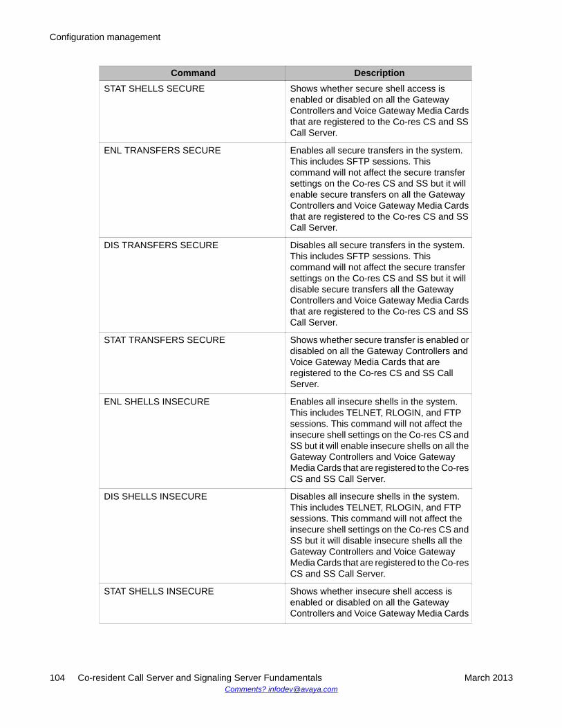
Command DescriptionSTAT SHELLS SECURE Shows whether secure shell access is
enabled or disabled on all the GatewayControllers and Voice Gateway Media Cardsthat are registered to the Co-res CS and SSCall Server.
ENL TRANSFERS SECURE Enables all secure transfers in the system.This includes SFTP sessions. Thiscommand will not affect the secure transfersettings on the Co-res CS and SS but it willenable secure transfers on all the GatewayControllers and Voice Gateway Media Cardsthat are registered to the Co-res CS and SSCall Server.
DIS TRANSFERS SECURE Disables all secure transfers in the system.This includes SFTP sessions. Thiscommand will not affect the secure transfersettings on the Co-res CS and SS but it willdisable secure transfers all the GatewayControllers and Voice Gateway Media Cardsthat are registered to the Co-res CS and SSCall Server.
STAT TRANSFERS SECURE Shows whether secure transfer is enabled ordisabled on all the Gateway Controllers andVoice Gateway Media Cards that areregistered to the Co-res CS and SS CallServer.
ENL SHELLS INSECURE Enables all insecure shells in the system.This includes TELNET, RLOGIN, and FTPsessions. This command will not affect theinsecure shell settings on the Co-res CS andSS but it will enable insecure shells on all theGateway Controllers and Voice GatewayMedia Cards that are registered to the Co-resCS and SS Call Server.
DIS SHELLS INSECURE Disables all insecure shells in the system.This includes TELNET, RLOGIN, and FTPsessions. This command will not affect theinsecure shell settings on the Co-res CS andSS but it will disable insecure shells all theGateway Controllers and Voice GatewayMedia Cards that are registered to the Co-resCS and SS Call Server.
STAT SHELLS INSECURE Shows whether insecure shell access isenabled or disabled on all the GatewayControllers and Voice Gateway Media Cards
Configuration management
104 Co-resident Call Server and Signaling Server Fundamentals March 2013Comments? [email protected]
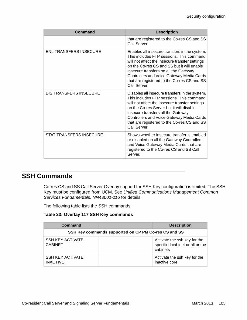
Command Descriptionthat are registered to the Co-res CS and SSCall Server.
ENL TRANSFERS INSECURE Enables all insecure transfers in the system.This includes FTP sessions. This commandwill not affect the insecure transfer settingson the Co-res CS and SS but it will enableinsecure transfers on all the GatewayControllers and Voice Gateway Media Cardsthat are registered to the Co-res CS and SSCall Server.
DIS TRANSFERS INSECURE Disables all insecure transfers in the system.This includes FTP sessions. This commandwill not affect the insecure transfer settingson the Co-res Server but it will disableinsecure transfers all the GatewayControllers and Voice Gateway Media Cardsthat are registered to the Co-res CS and SSCall Server.
STAT TRANSFERS INSECURE Shows whether insecure transfer is enabledor disabled on all the Gateway Controllersand Voice Gateway Media Cards that areregistered to the Co-res CS and SS CallServer.
SSH CommandsCo-res CS and SS Call Server Overlay support for SSH Key configuration is limited. The SSHKey must be configured from UCM. See Unified Communications Management CommonServices Fundamentals, NN43001-116 for details.
The following table lists the SSH commands.
Table 23: Overlay 117 SSH Key commands
Command DescriptionSSH Key commands supported on CP PM Co-res CS and SS
SSH KEY ACTIVATECABINET
Activate the ssh key for thespecified cabinet or all or thecabinets
SSH KEY ACTIVATEINACTIVE
Activate the ssh key for theinactive core
Security configuration
Co-resident Call Server and Signaling Server Fundamentals March 2013 105
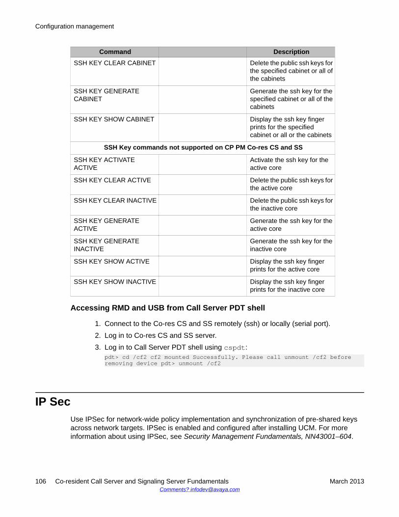
Command DescriptionSSH KEY CLEAR CABINET Delete the public ssh keys for
the specified cabinet or all ofthe cabinets
SSH KEY GENERATECABINET
Generate the ssh key for thespecified cabinet or all of thecabinets
SSH KEY SHOW CABINET Display the ssh key fingerprints for the specifiedcabinet or all or the cabinets
SSH Key commands not supported on CP PM Co-res CS and SS
SSH KEY ACTIVATEACTIVE
Activate the ssh key for theactive core
SSH KEY CLEAR ACTIVE Delete the public ssh keys forthe active core
SSH KEY CLEAR INACTIVE Delete the public ssh keys forthe inactive core
SSH KEY GENERATEACTIVE
Generate the ssh key for theactive core
SSH KEY GENERATEINACTIVE
Generate the ssh key for theinactive core
SSH KEY SHOW ACTIVE Display the ssh key fingerprints for the active core
SSH KEY SHOW INACTIVE Display the ssh key fingerprints for the inactive core
Accessing RMD and USB from Call Server PDT shell
1. Connect to the Co-res CS and SS remotely (ssh) or locally (serial port).2. Log in to Co-res CS and SS server.3. Log in to Call Server PDT shell using cspdt:
pdt> cd /cf2 cf2 mounted Successfully. Please call unmount /cf2 beforeremoving device pdt> unmount /cf2
IP SecUse IPSec for network-wide policy implementation and synchronization of pre-shared keysacross network targets. IPSec is enabled and configured after installing UCM. For moreinformation about using IPSec, see Security Management Fundamentals, NN43001–604.
Configuration management
106 Co-resident Call Server and Signaling Server Fundamentals March 2013Comments? [email protected]
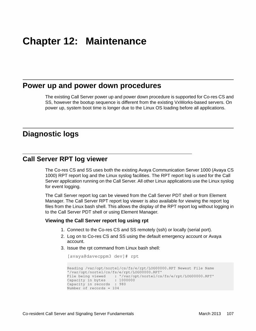
Chapter 12: Maintenance
Power up and power down proceduresThe existing Call Server power up and power down procedure is supported for Co-res CS andSS, however the bootup sequence is different from the existing VxWorks-based servers. Onpower up, system boot time is longer due to the Linux OS loading before all applications.
Diagnostic logs
Call Server RPT log viewerThe Co-res CS and SS uses both the existing Avaya Communication Server 1000 (Avaya CS1000) RPT report log and the Linux syslog facilities. The RPT report log is used for the CallServer application running on the Call Server. All other Linux applications use the Linux syslogfor event logging.
The Call Server report log can be viewed from the Call Server PDT shell or from ElementManager. The Call Server RPT report log viewer is also available for viewing the report logfiles from the Linux bash shell. This allows the display of the RPT report log without logging into the Call Server PDT shell or using Element Manager.
Viewing the Call Server report log using rpt
1. Connect to the Co-res CS and SS remotely (ssh) or locally (serial port).2. Log on to Co-res CS and SS using the default emergency account or Avaya
account.3. Issue the rpt command from Linux bash shell:
[avaya@davecppm3 dev]# rpt
Reading /var/opt/nortel/cs/fs/e/rpt/LOG00000.RPT Newest File Name "/var/opt/nortel/cs/fs/e/rpt/LOG00000.RPT"File being viewed : "/var/opt/nortel/cs/fs/e/rpt/LOG00000.RPT"Capacity in bytes : 1000000Capacity in records : 980Number of records = 104
Co-resident Call Server and Signaling Server Fundamentals March 2013 107
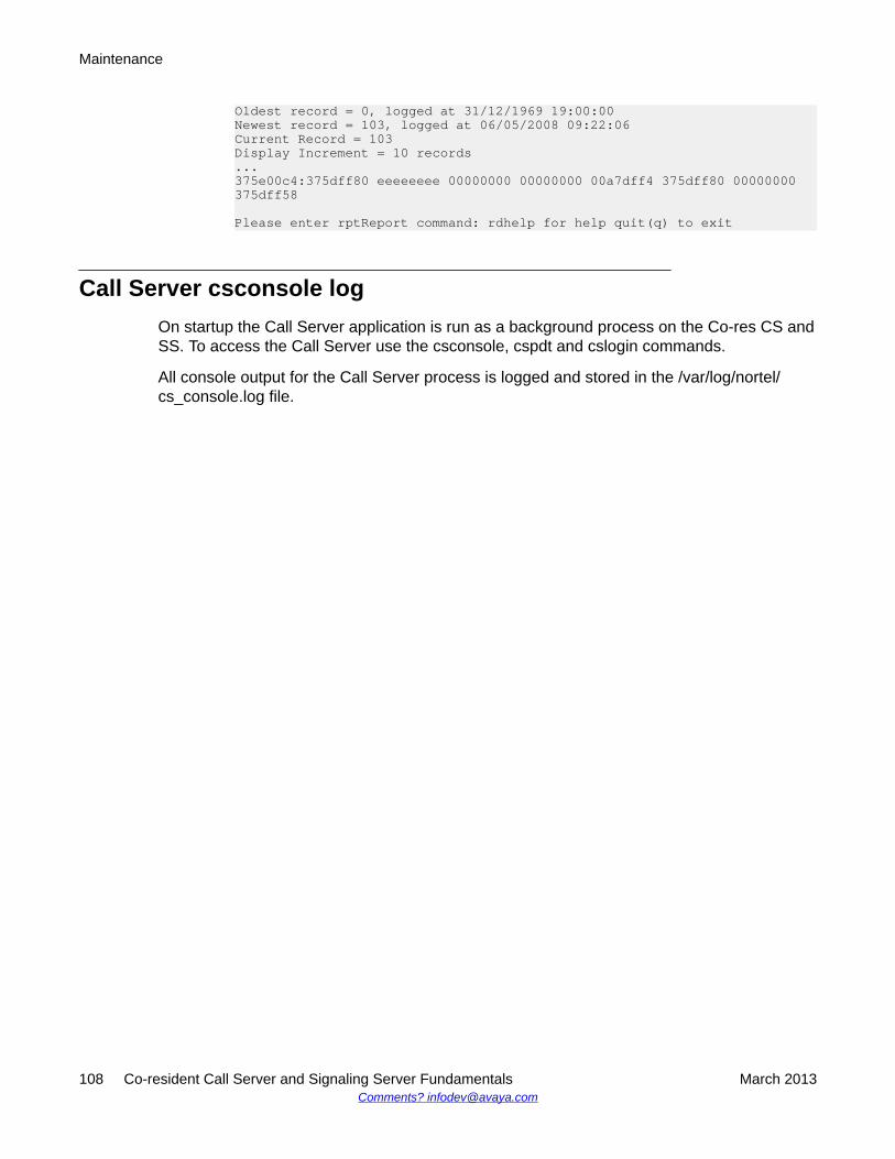
Oldest record = 0, logged at 31/12/1969 19:00:00Newest record = 103, logged at 06/05/2008 09:22:06Current Record = 103Display Increment = 10 records...375e00c4:375dff80 eeeeeeee 00000000 00000000 00a7dff4 375dff80 00000000 375dff58
Please enter rptReport command: rdhelp for help quit(q) to exit
Call Server csconsole logOn startup the Call Server application is run as a background process on the Co-res CS andSS. To access the Call Server use the csconsole, cspdt and cslogin commands.
All console output for the Call Server process is logged and stored in the /var/log/nortel/cs_console.log file.
Maintenance
108 Co-resident Call Server and Signaling Server Fundamentals March 2013Comments? [email protected]
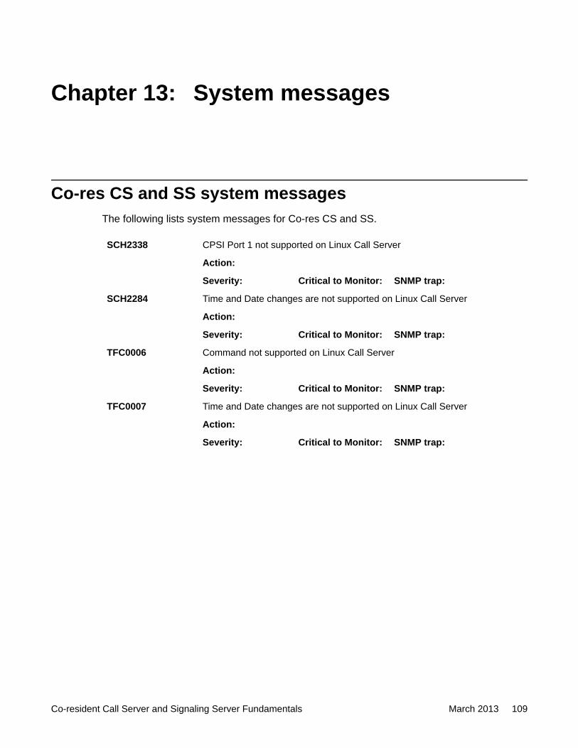
Chapter 13: System messages
Co-res CS and SS system messagesThe following lists system messages for Co-res CS and SS.
SCH2338 CPSI Port 1 not supported on Linux Call Server
Action:
Severity: Critical to Monitor: SNMP trap:
SCH2284 Time and Date changes are not supported on Linux Call Server
Action:
Severity: Critical to Monitor: SNMP trap:
TFC0006 Command not supported on Linux Call Server
Action:
Severity: Critical to Monitor: SNMP trap:
TFC0007 Time and Date changes are not supported on Linux Call Server
Action:
Severity: Critical to Monitor: SNMP trap:
Co-resident Call Server and Signaling Server Fundamentals March 2013 109

System messages
110 Co-resident Call Server and Signaling Server Fundamentals March 2013Comments? [email protected]


