U.P.B. Sci. Bull., Series D, Vol. 75, Iss. 2, 2013 ISSN 1454-2358 CONSIDERATIONS REGARDING ROUNDNESS MEASUREMENT OF CLOSED PROFILES AND OPEN PROFILES Daniela CIOBOATĂ 1 , Doru Dumitru PALADE 2 , Dănuţ STANCIU 3 , Aurel ABĂLARU 4 This paper presents some considerations regarding the optimization of shape deviations measurement then open or closed circular profiles. The paper analyzes the differences between the measurement and evaluation techniques for open and closed circular profiles. Some factors affecting the measurement accuracy are analyzed and a model of numerical simulation to assess the errors introduced by measurement software based on least squares method is presented. Keyword: roundness, open profile, closed profile, least squares method, eccentricity 1. Introduction The geometric shape accuracy is one of the four issues of interest regarding the manufacturing accuracy (dimensional precision, accuracy of the geometric shapes, precision of the mutual position of the surfaces, quality of the surfaces). Dimensional, shape and position deviations control is very important because the technological processes give: - Assurance of the product quality; - Inshapeation about processes; - Process control. The measurement of parts roundness is very important for manufacturing industry (for crankshafts, camshafts, bearings and guides measurement). The manner of determining the shape deviations influences the accuracy and functionality of the mechanisms. The circular shape is one of the most important geometric primitive shapes. Numerous devices and instruments depend critically on the rotation. 1 Eng., National Institute for Mechatronics and Measurement Techniques - INCDMTM Bucharest, Romania, e-mail: [email protected]2 Phd. Eng., National Institute for Mechatronics and Measurement Techniques – INCDMTM, Romania, Bucharest, e-mail: [email protected]3 Eng., National Institute for Mechatronics and Measurement Techniques - INCDMTM Bucharest, Romania, E-mail: [email protected]4 Phd. Eng., National Institute for Mechatronics and Measurement Techniques - INCDMTM Bucharest , Romania, e-mail: [email protected]
CONSIDERATIONS REGARDING ROUNDNESS MEASUREMENT OF CLOSED PROFILES AND OPEN
PROFILES
Daniela CIOBOATĂ1, Doru Dumitru PALADE2, Dănuţ STANCIU3, Aurel ABĂLARU4
This paper presents some considerations regarding the optimization of shape deviations measurement then open or closed circular profiles. The paper analyzes the differences between the measurement and evaluation techniques for open and closed circular profiles. Some factors affecting the measurement accuracy are analyzed and a model of numerical simulation to assess the errors introduced by measurement software based on least squares method is presented.
Keyword: roundness, open profile, closed profile, least squares method,
eccentricity
1. Introduction
The geometric shape accuracy is one of the four issues of interest regarding the manufacturing accuracy (dimensional precision, accuracy of the geometric shapes, precision of the mutual position of the surfaces, quality of the surfaces).
Dimensional, shape and position deviations control is very important because the technological processes give:
- Assurance of the product quality; - Inshapeation about processes; - Process control. The measurement of parts roundness is very important for manufacturing
industry (for crankshafts, camshafts, bearings and guides measurement). The manner of determining the shape deviations influences the accuracy and functionality of the mechanisms.
The circular shape is one of the most important geometric primitive shapes. Numerous devices and instruments depend critically on the rotation. 1 Eng., National Institute for Mechatronics and Measurement Techniques - INCDMTM Bucharest, Romania, e-mail: [email protected] 2 Phd. Eng., National Institute for Mechatronics and Measurement Techniques – INCDMTM, Romania, Bucharest, e-mail: [email protected] 3 Eng., National Institute for Mechatronics and Measurement Techniques - INCDMTM Bucharest, Romania, E-mail: [email protected] 4 Phd. Eng., National Institute for Mechatronics and Measurement Techniques - INCDMTM Bucharest , Romania, e-mail: [email protected]
130 Daniela Cioboata, Doru Dumitru Palade, Danut Stanciu, Aurel Abalaru
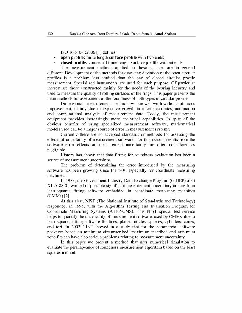
ISO 16 610-1:2006 [1] defines: - open profile: finite length surface profile with two ends; - closed profile: connected finite length surface profile without ends.
The measurement methods applied to these surfaces are in general different. Development of the methods for assessing deviation of the open circular profiles is a problem less studied than the one of closed circular profile measurement. Specialized instruments are used for such purpose. Of particular interest are those constructed mainly for the needs of the bearing industry and used to measure the quality of rolling surfaces of the rings. This paper presents the main methods for assessment of the roundness of both types of circular profile.
Dimensional measurement technology knows worldwide continuous improvement, mainly due to explosive growth in microelectronics, automation and computational analysis of measurement data. Today, the measurement equipment provides increasingly more analytical capabilities. In spite of the obvious benefits of using specialized measurement software, mathematical models used can be a major source of error in measurement systems.
Currently there are no accepted standards or methods for assessing the effects of uncertainty of measurement software. For this reason, results from the software error effects on measurement uncertainty are often considered as negligible.
History has shown that data fitting for roundness evaluation has been a source of measurement uncertainty.
The problem of determining the error introduced by the measuring software has been growing since the '80s, especially for coordinate measuring machines.
In 1988, the Government-Industry Data Exchange Program (GIDEP) alert X1-A-88-01 warned of possible significant measurement uncertainty arising from least-squares fitting software embedded in coordinate measuring machines (CMMs) [2].
At this alert, NIST (The National Institute of Standards and Technology) responded, in 1995, with the Algorithm Testing and Evaluation Program for Coordinate Measuring Systems (ATEP-CMS). This NIST special test service helps to quantify the uncertainty of measurement software, used by CMMs, due to least-squares fitting software for lines, planes, circles, spheres, cylinders, cones, and tori. In 2002 NIST showed in a study that for the commercial software packages based on minimum circumscribed, maximum inscribed and minimum zone fits can have also serious problems relating to measurement uncertainty.
In this paper we present a method that uses numerical simulation to evaluate the pershapeance of roundness measurement algorithm based on the least squares method.
Considerations regarding roundness measurement of closed profiles and open profiles 131
2. Roundness assessment methods
For roundness deviation measuring, different methods and measuring equipment can be used, from universal up to very special measuring devices.
The most accurate method for determining roundness of a component is to measure the variation of radius from an accurate rotational datum using a scanning probe. The probe must remain in contact with the surface and collects a high density of data points. Assessment of roundness is based on the use of reference futures which are fitted to the data. Shape errors of the components are measured relative to these futures.
Frequently, the surfaces of the workpieces are not full and their profiles determined in certain cross-sections are non-closed circle. These profiles can be evaluated also in relation to various reference elements.
The reference circles for roundness measurement are standardized by ISO 12181-1:2011, ANSI-B89.3.1:1994 and other standards in the world.
Standardization of reference elements for roundness measurement is important to ensure that measurements made with different equipment are compatible.
Four reference elements are internationally accepted for roundness measurement defined as follows [3]:
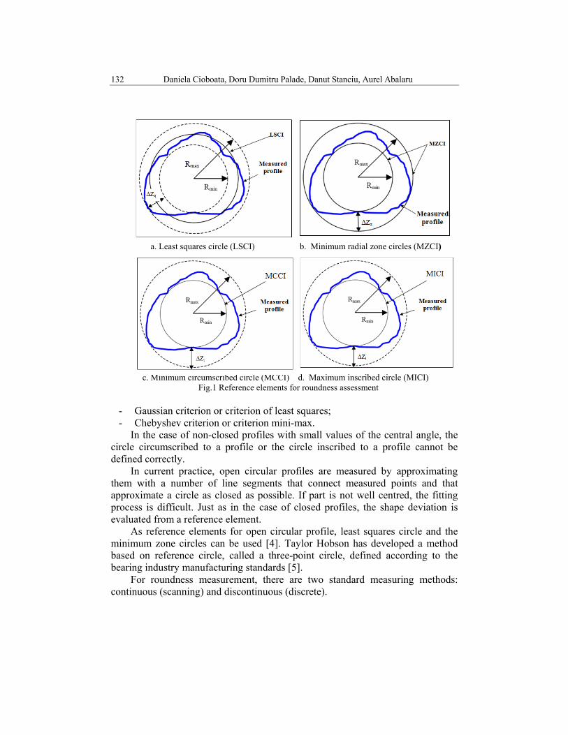
- Least squares circle (LSCI): circle such that the sum of the squares of the local roundness deviations is a minimum (figure 1 a);
- Minimum radial zone circles (MZCI): two concentric circles enclosing the roundness profile and having the least radial separation (figure 1 b);
- Minimum circumscribed circle (MCCI): smallest possible circle that can be fitted around the roundness profile (figure 1 c);
- Maximum inscribed circle (MICI): largest possible circle that can be fitted within the roundness profile (figure 1 d).
Whatever the method of roundness evaluation is used, the following steps are needed:
First step: determination of the reference figure center from which to determine the out of roundness;
The second step: determination of the reference circle radius; The third step: out of roundness assessment. The main criteria used for solving the above mentioned assessment methods are:
132 Daniela Cioboata, Doru Dumitru Palade, Danut Stanciu, Aurel Abalaru
a. Least squares circle (LSCI) b. Minimum radial zone circles (MZCI)
c. Minimum circumscribed circle (MCCI) d. Maximum inscribed circle (MICI)
Fig.1 Reference elements for roundness assessment
- Gaussian criterion or criterion of least squares; - Chebyshev criterion or criterion mini-max.
In the case of non-closed profiles with small values of the central angle, the circle circumscribed to a profile or the circle inscribed to a profile cannot be defined correctly.
In current practice, open circular profiles are measured by approximating them with a number of line segments that connect measured points and that approximate a circle as closed as possible. If part is not well centred, the fitting process is difficult. Just as in the case of closed profiles, the shape deviation is evaluated from a reference element.
As reference elements for open circular profile, least squares circle and the minimum zone circles can be used [4]. Taylor Hobson has developed a method based on reference circle, called a three-point circle, defined according to the bearing industry manufacturing standards [5].
For roundness measurement, there are two standard measuring methods: continuous (scanning) and discontinuous (discrete).
Considerations regarding roundness measurement of closed profiles and open profiles 133
The continuous method provides more detailed inshapeation about workpiece and measuring surface. There is a shorter distance between points at continuous measurement method (figure 2 a)[6], than for the detailed discontinuous method. But the measuring time is longer. This method has advantage in equivalent results at repeatable measuring and during change position of measured part. The question is which is the optimum number of measured points for a given measurement task.
At discontinuous method, the distance between data points is greater (Fig. 2 b) [6]. Results are relatively inaccurate and do not provide full inshapeation about shape and size of measured surface. Repeatable measurement of workpieces with low point numbers leads to various results.
a. Data points – continuous method b. Data points – discontinuous method (CMM) Fig.2 Distance between datapoints in case of continuous and discontinuous methods
3. Factors affecting the accuracy of roundness measurement
Some of the most important factors that affect the result of the roundness measurement are: the number of measuring points, their distribution and the fitting element.
Because of computational algorithms and approximations, the out-of-roundness value may differ depending on the algorithm used for fitting element assessment. The smallest possible value for the out-of-roundness of a given profile is the one determined by MZCI assessment. The out-of-roundness determined by LSC varied from 1% to more than 20% over those assessments by MZCI, while values obtained by MICI and MCCI methods are generally somewhat larger than those determined by the LSCI method [7].
The LSCI is the most commonly method used in practice for out-of-roundness measurement, because of its simplicity. This is a well understood and fast method having a smaller number of unknown parameters.
Other advantages of LSCI method are: - it is less affected by extreme radial coordinates, because the circle of least
squares is determined based on average of all measured points on the periphery of the profile;
- it is unique determined;
134 Daniela Cioboata, Doru Dumitru Palade, Danut Stanciu, Aurel Abalaru
- allows changing of the coordinate system by translation and rotation the measured profile.
Experience has shown that the result of LSCI method is influenced by the number of measured points and by eccentricity between the profile centre and rotation centre.
We performed a numerical simulation method to determine the influence of measured points, eccentricity and radius of the profile on the error of assessment the roundness. This testing method allows to choose the optimum number of samples with respect to the desired measurement accuracy and to analyze the influence of eccentricity of the workpiece on measurement accuracy.
It also allowed testing of the measurement software to determine the measurement uncertainty.
4. Numerical simulation method
The method is based on simulated points acquisition by generating N number of random data points Δi, with normal distribution.
2
1
0
2
1
0
=Δ
=
Δ=
−=Δ
∑
∑
=
−
=
N
N
t)t;rand(
N
i
N
ii
i
i
σ
μ (1)
where : - t and t are lower and upper tolerance limits of the considered profile; μ is the mean value σ is the standard deviation of the mean (for a 95,45% confidence level).
The out of roundness is: iMINiMAXCAF Δ−Δ= (2)
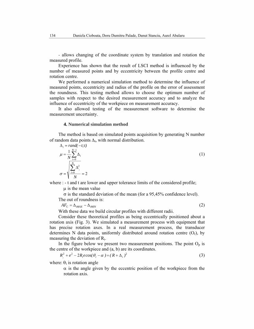
With these data we build circular profiles with different radii. Consider these theoretical profiles as being eccentrically positioned about a
rotation axis (Fig. 3). We simulated a measurement process with equipment that has precise rotation axes. In a real measurement process, the transducer determines N data points, uniformly distributed around rotation centre (Or), by measuring the deviation of Ri.
In the figure below we present two measurement positions. The point Op is the centre of the workpiece and (a, b) are its coordinates.
222 2 )R()cos(eReR iiiiΔ+=−−+ αθ (3)
where: θi is rotation angle α is the angle given by the eccentric position of the workpiece from the rotation axis.
Considerations regarding roundness measurement of closed profiles and open profiles 135
Fig.3 Measurement process diagram
αα
πθ
sinb
cosae
N,...,i,N
i*i
==
−=−
= 101
2
(4)
To simplify calculations we consider a=b. The solutions of equation (3) are:
( )
( )2
454454522
45445452
22
22
)]sin/b()R[()sin/b(sin/b
])R()sin/b[()sin/b(sin/bR
i
ii
°−Δ++°±°
=Δ+−°−°±°
= (5)
Because b and a are much smaller than R, the solution with the plus sign in the shapeula 5, is considered.
After determining the Ri values, the coordinate xi and yi of each Pi point are calculated.
iii
iiisinRycosRx
θθ
== (6)
These are the theoretical coordinates of Pi points on the periphery of the considered profile, in the equipment coordinate system.
These values are used to determine: - the radius of LSCI (RLSC)
∑−
=
=1
0
1 N
iiLSC R
NR (7)
- the eccentricity of LSC from the centre of rotation (aLSC, bLSC)
∑∑−
=
−
=
==1
0
1
0
22 N
iiLSC
N
iiLSC y
Nb;x
Na (8)
- out-of-roundness (ΔZq)
136 Daniela Cioboata, Doru Dumitru Palade, Danut Stanciu, Aurel Abalaru
iLSCiLSCLSCiq sinbcosaRRZ θθ −−−=Δ (9)
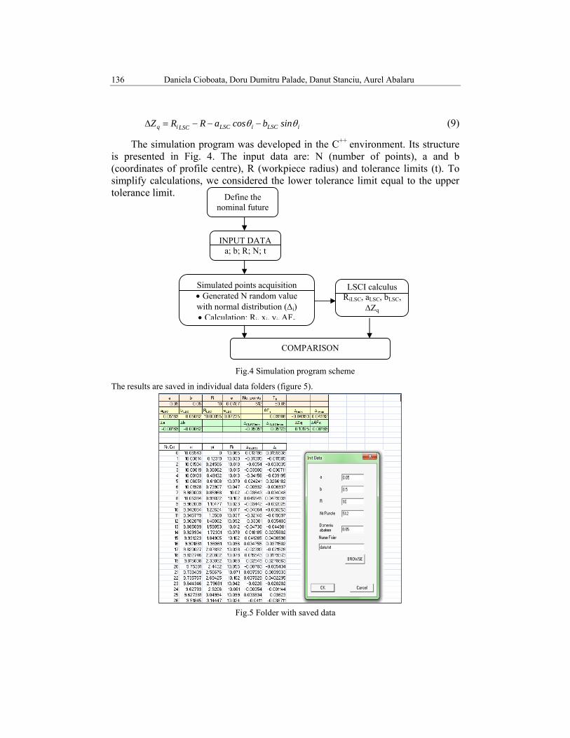
The simulation program was developed in the C++ environment. Its structure is presented in Fig. 4. The input data are: N (number of points), a and b (coordinates of profile centre), R (workpiece radius) and tolerance limits (t). To simplify calculations, we considered the lower tolerance limit equal to the upper tolerance limit.
Fig.4 Simulation program scheme
The results are saved in individual data folders (figure 5).
Fig.5 Folder with saved data
INPUT DATA a; b; R; N; t
Define the nominal future
Simulated points acquisition • Generated N random value with normal distribution (Δi) • Calculation: Ri, xi, yi, AFc
LSCI calculus RiLSC, aLSC, bLSC,
ΔZq
COMPARISON
Considerations regarding roundness measurement of closed profiles and open profiles 137
4. Results
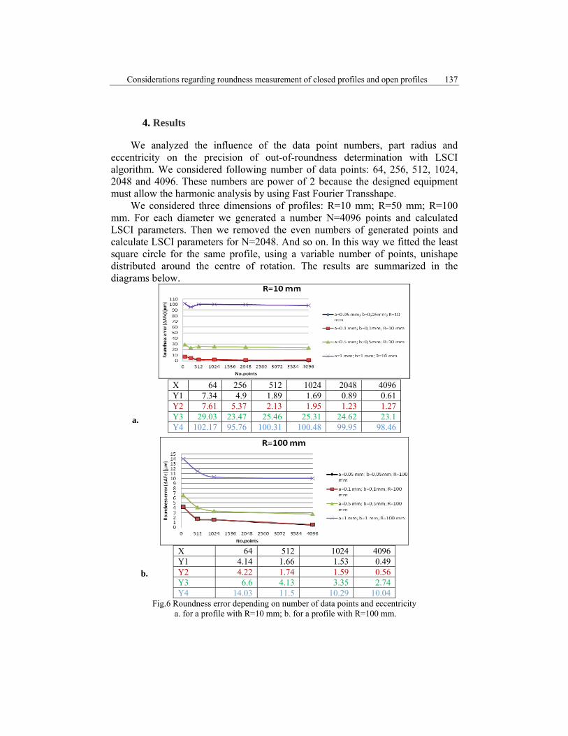
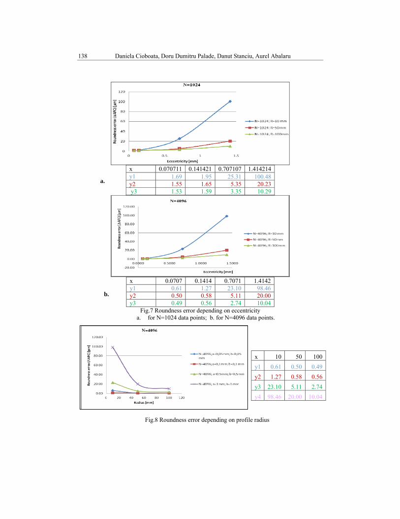
We analyzed the influence of the data point numbers, part radius and eccentricity on the precision of out-of-roundness determination with LSCI algorithm. We considered following number of data points: 64, 256, 512, 1024, 2048 and 4096. These numbers are power of 2 because the designed equipment must allow the harmonic analysis by using Fast Fourier Transshape.
We considered three dimensions of profiles: R=10 mm; R=50 mm; R=100 mm. For each diameter we generated a number N=4096 points and calculated LSCI parameters. Then we removed the even numbers of generated points and calculate LSCI parameters for N=2048. And so on. In this way we fitted the least square circle for the same profile, using a variable number of points, unishape distributed around the centre of rotation. The results are summarized in the diagrams below.
Considerations regarding roundness measurement of closed profiles and open profiles 139
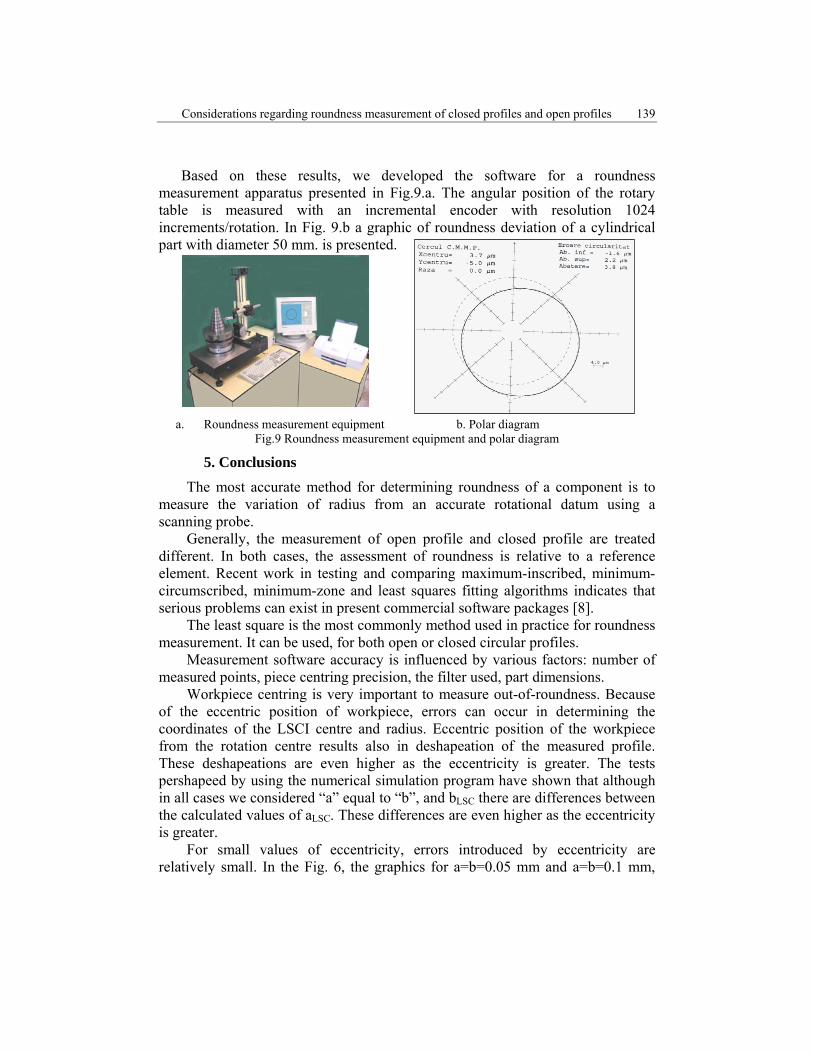
Based on these results, we developed the software for a roundness measurement apparatus presented in Fig.9.a. The angular position of the rotary table is measured with an incremental encoder with resolution 1024 increments/rotation. In Fig. 9.b a graphic of roundness deviation of a cylindrical part with diameter 50 mm. is presented.
a. Roundness measurement equipment b. Polar diagram Fig.9 Roundness measurement equipment and polar diagram
5. Conclusions
The most accurate method for determining roundness of a component is to measure the variation of radius from an accurate rotational datum using a scanning probe.
Generally, the measurement of open profile and closed profile are treated different. In both cases, the assessment of roundness is relative to a reference element. Recent work in testing and comparing maximum-inscribed, minimum-circumscribed, minimum-zone and least squares fitting algorithms indicates that serious problems can exist in present commercial software packages [8].
The least square is the most commonly method used in practice for roundness measurement. It can be used, for both open or closed circular profiles.
Measurement software accuracy is influenced by various factors: number of measured points, piece centring precision, the filter used, part dimensions.
Workpiece centring is very important to measure out-of-roundness. Because of the eccentric position of workpiece, errors can occur in determining the coordinates of the LSCI centre and radius. Eccentric position of the workpiece from the rotation centre results also in deshapeation of the measured profile. These deshapeations are even higher as the eccentricity is greater. The tests pershapeed by using the numerical simulation program have shown that although in all cases we considered “a” equal to “b”, and bLSC there are differences between the calculated values of aLSC. These differences are even higher as the eccentricity is greater.
For small values of eccentricity, errors introduced by eccentricity are relatively small. In the Fig. 6, the graphics for a=b=0.05 mm and a=b=0.1 mm,
140 Daniela Cioboata, Doru Dumitru Palade, Danut Stanciu, Aurel Abalaru
are almost superimposed. For a=b=1 mm the errors in determining the roundness are much larger.
The number of measuring points also influences the accuracy of determining the roundness value. As the number of points increases, accuracy of measurement is higher. It is found that for N=64…512 points and R=10 mm, the errors of determining the roundness value have significant variations (Fig. 6 a). Similar for N=64…1024 points and R=100 mm (figure 6 b). For a larger number of points, the graphs are approximately linear.
This testing method allowed us to choose the rotary incremental transducer to obtain an optimal number of data points required with respect to desired measurement accuracy and to analyze the influence of eccentric positioning of the workpiece from the rotation axis of measurement equipment that we designed.
The experiments presented in this paper were made by simulating a scanning process without filtering data. The results reveal errors introduced by the LSCI algorithm. In metrological practice, scanning without filter gives significantly higher roundness values, than when using Gauss or other filters.
For accurate measurement of roundness by scanning are recommended: use of an adequate number of measured points; more accurate centring of the workpiece from the axes of rotation; raw data filtering.
R E F E R E N C E S
[1] ISO 16610/TS-1:2006, Geometrical product specifications (GPS) — Filtration —Part 1: Overview and basic concepts
[2] C. Diaz, Algorithm Testing and Evaluation Program for Coordinate Measuring Systems: Testing Methods, NISTIR 5686, U.S. Department of Commerce, National Institute of Standards and Technology (NIST), July 1995
[3] ISO 12181-1:2011, Geometrical product specifications (GPS) ― Roundness, Part 1: Vocabulary and parameters of roundness
[4] D. Whitehouse, Surfaces and their Measurement, Editura: Hermes Penton, London 2002, ISBN: 9781903996010
[5] S. Adamczak, D. Janecki, Problems concerning the measurement of shape profiles of non-closed cylindrical surfaces of machine parts, Measurement Science Review, vol.1, no.1, 2001 147-150
[6] L. Ocenasova, B. Gapinski, R. Cep, L. Gregova, B. Barisic, J. Novakova, and L. Petrkovska, Roundness Deviation Measuring Strategy at Coordination Measuring Machines and Conventional Machines, World Academy of Science, Engineering and Technology 56 2009, 523-526
[7] ANSI-B89.3.1: 1994, Out of Roundness, Measurement [8] C. Shakarj, A Look at Mathematical and Computational Issues in Manufacturing Inspection
Using Coordinate Measuring Machines, Manufacturing Engineering Laboratory, NIST, 2006 [9] A. Görög, Number of Points for Roundness Measurement – Measured Results Comparison,
Faculty of Materials Science and Technology in Trnava, Slovak University of Technology in Bratislava, Number 30 2011