30
CONTRACT DOCUMENTS PRE-PROCUREMENT FOR ALVARADO HYDROELECTRIC FACILITY REHABILITATION SPECIFICATION 647A ADDENDUM NO. 3 San Diego County Water Authority

CONTRACT DOCUMENTS
PRE-PROCUREMENT FOR
ALVARADO HYDROELECTRIC FACILITY REHABILITATION
SPECIFICATION 647 A
ADDENDUM NO. 3
San Diego County Water Authority

File: Q0333.010.2 - Addendum 3.docx
ADDENDUM 3
SAN DIEGO COUNTY WATER AUTHORITY
PRE-PROCUREMENT FOR ALVARADO HYDROELECTRIC FACILITY REHABILITATION
SPECIFICATION 647A
January 25, 2018 The following ADDENDUM 3 shall be made part of the Contract Documents, and the bidder shall acknowledge receipt thereof on Page 3 of the bid proposal forms. Revisions are made to the Contract Documents as described below: I. REVISIONS TO VOLUME I OF II
A. Add General Conditions Section 1.2, Definitions, Paragraph (ll), as follows:
(ll) Professional Engineer: An individual licensed by a governmental agency to prepare,
sign, and seal engineering plans, drawings, and specifications.
B. Delete Section 01010, Project Summary, Part 1.04, Paragraph C, and replace with the following: C. Liquidated damages shall be assessed in the amount of $24,000 for each percent or
portion thereof the turbine generator efficiency is less than the guaranteed efficiencies identified in the Bid Proposal at the rated flow and head conditions. Efficiencies shall be determined by field tests performed in accordance with Section 11200, Turbine, in the presence of the Supplier. Efficiency liquidated damages shall not exceed 10 percent of total contract value. If tested efficiency is less than 95 percent of the guaranteed efficiency, the Engineer may reject the unit in its entirety and Supplier shall make corrections required to bring the unit within 95 percent efficiency or provide a new unit that will meet the guaranteed efficiency.
C. Delete Section 01311, Progress Schedules, Part 1.18, Paragraph H, and replace with the
following: H. If the Supplier does not submit a TIA for a specific change order or delay within the
specified time, the Engineer will decide the appropriate method for the Supplier to perform a schedule impact analysis. The Engineer’s decision on the chosen method will be final.
D. Delete Section 01640, Supplier’s Services, Part 1.01, Paragraph A, and replace with the
following: A. International Electrotechnical Commission
62006 Hydraulic machines - Acceptance tests of small hydroelectric installations 60041 Field acceptance tests to determine the hydraulic performance of hydraulic
turbines, storage pumps and pump-turbines

Addendum 3 – Pre-Procurement for Alvarado Hydroelectric Facility Rehabilitation, Specification 647A January 25, 2018 Page 2
File: Q0333.010.2 - Addendum 3.docx
E. Add Section 01640, Supplier’s Services, Part 1.04, Paragraph F, as follows:
F. The Supplier will not be compensated for days spent at the site to correct issues that
are a result of the Supplier’s non-conformance with the Contract Documents or other Supplier responsibilities including, but not limited to, warranty work.
F. Delete Section 01640, Supplier’s Services, Part 1.06, Paragraph E, and replace with the
following: E. Provide a list of turbine field tests to be conducted by the General Construction
Contractor. The tests shall include, at a minimum, efficiency performance testing in accordance with IEC 62006. After the Certificate of Proper Installation and Certified Field Test Results for each piece of equipment have been duly executed and issued, the turbine systems, including vibration monitoring, cooling water systems, and turbine isolation valve systems will be tested to demonstrate satisfactory operation and compliance with guarantees. Turbine representative shall make any adjustments necessary to ensure that the equipment supplied complies with guarantees. Turbine representative shall certify field tests are complete after the Certificate of Test Results has been duly executed and issued.
G. Delete Section 01701, Contract Closeout, in its entirety, and replace with Attachment 1/
Addendum 3.
H. Delete Section 11200, Turbine, Part 2.02, Paragraph A, and replace with the following. A. Runner. Supplier may manufacture the runner from either a solid machined forging,
or a one-piece casting or a combination of plate steel and castings, accurately machined, and ground on all exterior surfaces to provide a minimum 250 or better finish, and statically and dynamically balanced in manufacturer's shop. The water passages shall have uniform sections, smooth surfaces ground to a 125 finish and be free from hollows, depressions, cracks or projections that might cause local cavitation pitting. Surface waviness or fairness shall comply with the requirements of IEC 60193 for Francis turbine runners and have a waviness of less than 0.01. The runner shall be homologous to the model in its water passage.
I. Delete Section 11200, Turbine, Part 2.02, Paragraph H, Item 1, and replace with the
following: 1. The turbine runner shall be directly coupled to the generator shaft. The shaft shall be
as specified in Section 16210, Generator. The coupling key or flange and bolts shall be of ample size to operate at any speed up to the maximum runaway speed without detrimental vibration or distortion.
J. Delete Section 15120, Electric Motor Actuators, Part 2.01, Paragraph A, and replace with the
following:

Addendum 3 – Pre-Procurement for Alvarado Hydroelectric Facility Rehabilitation, Specification 647A January 25, 2018 Page 3
File: Q0333.010.2 - Addendum 3.docx
A. Actuators designated in the Contract Documents as “intelligent electric motor actuators” shall be Auma – SIPOS Seven, or equal.
K. Delete Section 16161, Panels, Cabinets, and Consoles, Part 2.02, Paragraph B, and replace
with the following: B. Construct control panel enclosures from formed 12-gauge steel. Grind all exposed
edges and welds on the enclosure smooth. Paint the exterior of the enclosure with a rust-inhibiting primer and two coats of epoxy paint or powder coat. Exterior finish color shall be ANSI 61 Gray. Provide formed 12-gauge steel subpanels for attaching surface-mounted components inside the cabinet. Attach all components with machine screws into threaded holes and include threaded connections on the subpanel. Do not use rivets or back of panel nuts.
L. Delete Section 16161, Panels, Cabinets, and Consoles, Part 2.02, Paragraph E, and replace with the following: E. Paint the interior of the enclosure with two coats of white gloss enamel or powder
coat white. The interior can be the same color as the exterior as long as the subpanels are painted white.
M. Delete Section 16161, Panels, Cabinets, and Consoles, Part 2.02, Paragraph H, Item 11, and replace with the following: 11. Isolation Amplifier (Signal Converter): Provide DIN-rail mounted 3-way isolation
amplifier which accepts a standard 4 to 20 mA DC input signal and provides an isolated 4 to 20 mA DC output. Isolation amplifiers shall be Phoenix Contact Model MINI MCR-SL-RPSS-I-I, no exceptions.
N. Delete Section 16161, Panels, Cabinets, and Consoles, Part 2.02, Paragraph I, Items 2 and 3, and replace with the following: 2. Primary Digital Directional Overcurrent and Non-Directional Overcurrent Protection
Relay (67P, 50P/51P, 67NP and 50NP/51NP), also including undervoltage (27P), overvoltage (59P), current unbalance (46), and under-frequency (81U) & over-frequency(81O) protection functions for 12,000V, 3-phase, 60 Hz, SDG&E interconnection line protection as shown on the metering and relay one-line diagram, also including RS485 ports and ModBus protocol, equipped with 125 volt dc power supply, suitable for 5A current transformer secondary, 60 Hz operating frequency, target module, A-B-C phase rotation, Schweitzer Engineering Laboratories.
3. Secondary Digital Directional Overcurrent and Non-Directional Overcurrent Protection Relay (67S, 50S/51S, 67NS and 50NS/51NS), also including undervoltage (27S), overvoltage (59S), current unbalance (46), and under-frequency (81U) & over-frequency(81O) protection functions for 12,000V, 3-phase, 60 Hz, SDG&E interconnection line protection as shown on the metering and relay one-line diagram, also including RS485 ports and ModBus protocol, equipped with 125 volt dc power

Addendum 3 – Pre-Procurement for Alvarado Hydroelectric Facility Rehabilitation, Specification 647A January 25, 2018 Page 4
File: Q0333.010.2 - Addendum 3.docx
supply, suitable for 5A current transformer secondary, 60 Hz operating frequency, target module, A-B-C phase rotation, Schweitzer Engineering Laboratories.
O. Delete Section 16161, Panels, Cabinets, and Consoles, Part 3.01, Paragraph A, and replace with the following: A. Complete, assemble, wire, and test each control panel and interface cabinet at the
factory. Test in accordance with the latest UL and NEMA Standards. Provide UL 508A label as applicable on all cabinets.
P. Delete Section 16210, Generator, Part 1.03, Paragraph D, and replace with the following:
D. The generator stator windings shall be in a Y configuration with the neutral
connected to ground through a distribution transformer which shall have a neutral grounding resistor connected to its secondary for generator ground protection. The neutral grounding equipment shall be located in a dedicated cubicle adjacent to the generator. The generator high voltage terminals shall also have a dedicated cubicle. Low resistance or reactor grounding methods may be allowed with approval by the Engineer.
Q. Delete Section 16210, Generator, Part 1.04, Paragraphs A and B in their entirety, and replace
with the following: A. National Electrical Manufacturers Association
MG 1 Motors and Generators (Section IV Performance Standards Applying To All
Machines, Part 32 – Synchronous Generators (Exclusive of Generators Covered by ANSI Standards C50.12, C50.13, C50.14, and C50.15 Above 5000 kVA) Ratings)
B. Institute of Electrical and Electronics Engineers
C50.12 Standard for Salient-Pole 50 Hz and 60 Hz Synchronous Generators and Generator/Motors for Hydraulic Turbine Applications Rated 5 MVA and Above
43 Recommended Practice for Testing Insulation Resistance of Rotating
Machinery 85 Test Procedure for Airborne Sound Measurements on Rotating Electric
Machinery 115 Test Procedure for Airborne Sound Measurements on Rotating Electric
Machinery 286 Recommended Practice for Measurement of Power Factor Tip-Up of Electric
Machinery Stator Coil Insulation

Addendum 3 – Pre-Procurement for Alvarado Hydroelectric Facility Rehabilitation, Specification 647A January 25, 2018 Page 5
File: Q0333.010.2 - Addendum 3.docx
522 Guide for Testing Turn Insulation of Form-Wound Stator Coils for Alternating-Current Electric Machines
810 Standard for Hydraulic Turbine and Generator Shaft Couplings and Shaft
Runout Tolerances
R. Delete Section 16210, Generator, Part 1.06, Paragraph A, Item 5, and replace with the following: 5. Range of Operating Voltage +10%
Range of Voltage Regulation +0.5%
S. Delete Section 16210, Generator, Part 2.02, Paragraph C, Items 1 and 2, and replace with the following: 1. The shaft shall be accurately machined and finished and shall have forged flanges
conforming to ANSI B49.1 or plain shaft end with key. Machine the shaft flanges and ends as necessary to properly connect the turbine runner to the generator shaft.
2. Runout shall be checked by rotating the generator shaft and aligning the generator,
runner, and spiral case in the turbine manufacturer's shop in accordance with Section 11200, Turbine, Part 2.06. Runout shall not exceed tolerances recommended in the IEEE 810.
T. Delete Section 16210, Generator, Part 2.02, Paragraph D, Items 2 and 3, and replace with the
following: 2. Provide a combined babbit lined, oil lubricated thrust and guide bearing between the
turbine and generator. It shall be of the latest design, with ample capacity to support axial thrust and counter thrust in both directions parallel to shaft axis under the most unfavorable operating conditions.
3. Provide one babbit lined, oil lubricated outboard guide bearing for the generator. The
lubrication system for the bearings may be self lubricated slinger rings or a self-contained lubricating system including oil reservoirs, oil piping, valves, and necessary appurtenances. Line all surfaces in contact with the shaft with white antifriction metal.
U. Delete Section 16210, Generator, Part 2.04, Paragraph D, Item 1, and replace with the
following: 1. Provide an adequate number of space heaters evenly distributed in the air housing to
prevent condensation of moisture on the windings when the generator is idle and ambient temperature is below 40°C. The space heaters shall be suitable for operation on a 480 VAC, 3 phase, 60 Hz or 120 VAC, single phase, 60 Hz source. Arrange the space heaters so that the load is approximately equally distributed between the
Addendum 3 – Pre-Procurement for Alvarado Hydroelectric Facility Rehabilitation, Specification 647A January 25, 2018 Page 6
File: Q0333.010.2 - Addendum 3.docx
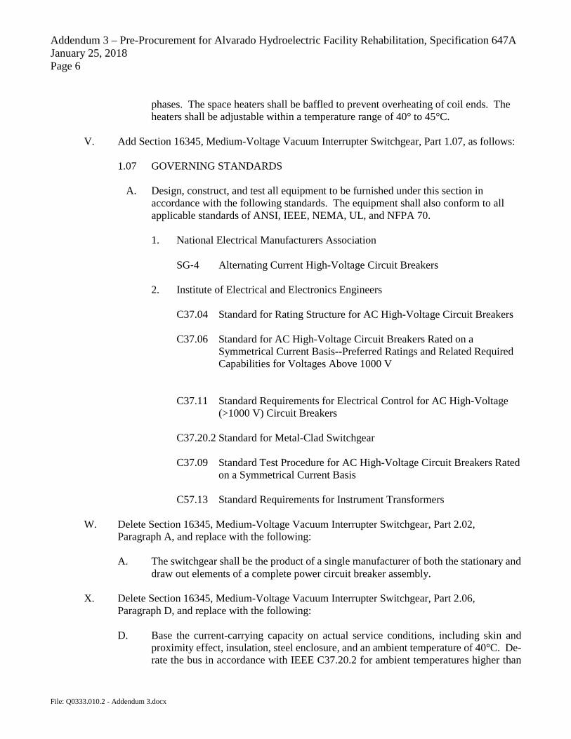
phases. The space heaters shall be baffled to prevent overheating of coil ends. The heaters shall be adjustable within a temperature range of 40° to 45°C.
V. Add Section 16345, Medium-Voltage Vacuum Interrupter Switchgear, Part 1.07, as follows:
1.07 GOVERNING STANDARDS
A. Design, construct, and test all equipment to be furnished under this section in accordance with the following standards. The equipment shall also conform to all applicable standards of ANSI, IEEE, NEMA, UL, and NFPA 70.
1. National Electrical Manufacturers Association
SG‑4 Alternating Current High-Voltage Circuit Breakers
2. Institute of Electrical and Electronics Engineers
C37.04 Standard for Rating Structure for AC High-Voltage Circuit Breakers C37.06 Standard for AC High-Voltage Circuit Breakers Rated on a
Symmetrical Current Basis--Preferred Ratings and Related Required Capabilities for Voltages Above 1000 V
C37.11 Standard Requirements for Electrical Control for AC High-Voltage
(>1000 V) Circuit Breakers C37.20.2 Standard for Metal-Clad Switchgear C37.09 Standard Test Procedure for AC High-Voltage Circuit Breakers Rated
on a Symmetrical Current Basis C57.13 Standard Requirements for Instrument Transformers
W. Delete Section 16345, Medium-Voltage Vacuum Interrupter Switchgear, Part 2.02, Paragraph A, and replace with the following: A. The switchgear shall be the product of a single manufacturer of both the stationary and
draw out elements of a complete power circuit breaker assembly.
X. Delete Section 16345, Medium-Voltage Vacuum Interrupter Switchgear, Part 2.06, Paragraph D, and replace with the following: D. Base the current-carrying capacity on actual service conditions, including skin and
proximity effect, insulation, steel enclosure, and an ambient temperature of 40°C. De-rate the bus in accordance with IEEE C37.20.2 for ambient temperatures higher than

Addendum 3 – Pre-Procurement for Alvarado Hydroelectric Facility Rehabilitation, Specification 647A January 25, 2018 Page 7
File: Q0333.010.2 - Addendum 3.docx
40°C. Supply the bus in unit lengths that will permit the reassembly of the units in the field.
Y. Delete Section 16910, Programmable Logic Controller, Part 1.06, Paragraph A, and replace
with the following: A. Provide a network of field sales and support personnel in San Diego County. They
shall provide product application assistance by trained and experienced engineers to assist with system development, to include initial system start up, selection of PLC hardware, I/O and communication module selection, development of ladder logic programming and troubleshooting through telephone consultation and on-site support.
Z. Delete Section 16910, Programmable Logic Controller, Part 2.10, Paragraph C, and replace
with the following: C. Provide a written five year guaranty to the continuing availability of all hardware, or
its equivalent replacement. The guaranty shall include all PLC modules, power supplies controllers, chassis/backplane, and other panel-mounted devices.
AA. Delete Section 16911, Programming Software for Programmable Logic Controller, Part 1.05,
Paragraph A, and replace with the following: A. The manufacturer shall have a network of field sales and support personnel in San
Diego County, providing product application assistance by trained and experienced engineers to design, configure, de-bug and maintain a PLC’s ladder-logic/function block program through telephone consultation and on-site checkout. This support service shall also be available seven days a week and 24 hours per day if emergency assistance is required.
BB. Delete Section 16911, Programmable Logic Controller, Part 2.06, Paragraph A, and replace
with the following: A. Deliver the programming software to the Water Authority’s Escondido Office at 610
W. Fifth Ave, Escondido, CA 92025. Deliver the software unopened, in the manufacturer’s packaging, free of any shipping damage. The Water Authority will inspect the software before unpacking and will reject any items that appear to be damaged during shipping.
CC. Delete Section 16911, Programmable Logic Controller, Part 2.07, Paragraph C, and replace
with the following: C. Provide a written five year guaranty to the continuing availability of all programming
software, or its equivalent replacement, that was provided. The guaranty shall cover all programming software for the PLC series hardware provided including configuration of I/O, communication links and drivers, and memory management.

Addendum 3 - Pre-Procurement for Alvarado Hydroelectric Facility Rehabilitation, Specification 64 7 A January 25, 2018 Page 8
DD. Delete Appendix C, Unit and Master PLC 1/0 Lists, and replace with Attachment 2/Addendum 3.
II. REVISIONS TO VOLUME II OF II
A. Delete the Turbine/Generator- Guaranteed Performance Worksheet in the Bid Proposal and replace with Attachment 3/Addendum 3.
Ill REVISIONS TO THE PLANS
A. Delete Note 4 on Drawing M-1, Hydroelectric Facility Plan, and replace with the following:
4. Preliminary Turbine/Generator footprint shown for reference. Footprint of actual turbine generator furnished shall maintain minimum clearances shown.
B. Delete Drawing 1-3, SD28/Alvarado Facility Overview, and replace with Attachment 4/Addendum 3.
C. Delete Drawing 1-4, Flow Control Valve, and replace with Attachment 5/Addendum 3.
D. Delete Drawing 1-5, Turbine/Generator, and replace with Attachment 6/Addendum 3.
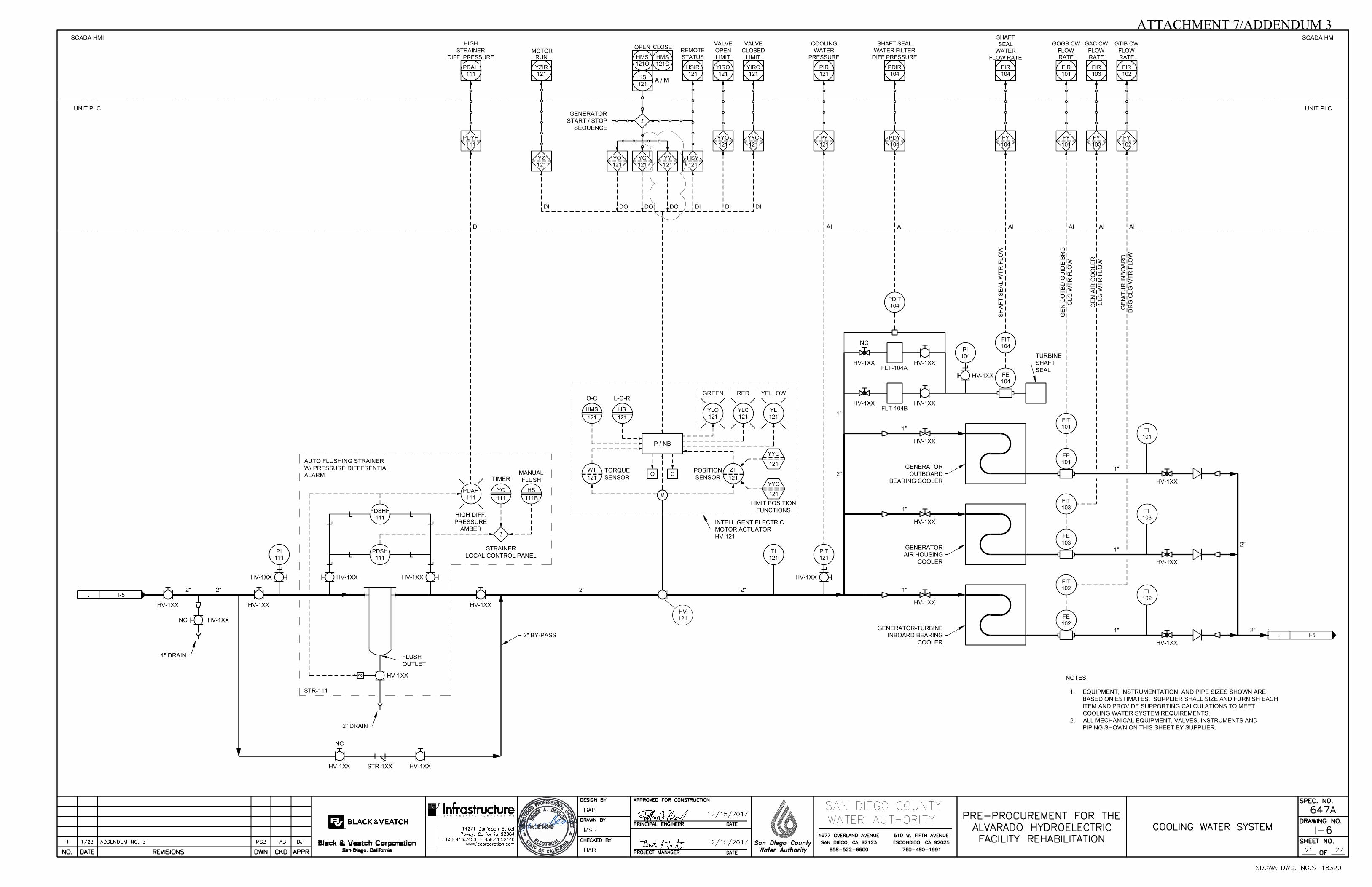
E. Delete Drawing 1-6, Cooling Water System, and replace with Attachment 7/Addendum 3.
F. Delete Drawing 1-8, Panel Layout, and replace with Attachment 8/Addendum 3.
IV. QUESTIONS AND ANSWERS
See Attachment 9/ Addendum 3 for questions and answers.
SAN DIEGO COUNTY WATER AUTHORITY
Jerry Dir ctor of Engineering
File: Q0333 .0I0.2 -Addendum 3.docx

ATTACHMENT 1/ADDENDUM 3
SPECIFICATION 647A CONTRACT CLOSEOUT JANUARY 25, 2018 01701 - 1 File: Q0333.010.2 - Att 1 01701 Contract Closeout.docx
SECTION 01701 - CONTRACT CLOSEOUT
PART 1 - GENERAL
1.01 DEFINITIONS
A. Punchlist: A list of incomplete and defective Work as identified in the Plans and Specifications.
1.02 FINAL INSPECTION REQUEST
A. Before requesting the final inspection, submit the following items to the Engineer:
1. Operating manuals and instructions. 2. Maintenance stock items; spare parts; special tools. 3. Certificates of inspection and written acceptance by permittee, local governing agencies having
jurisdiction, and property owners. 4. All required vendor training, testing, and startup.
B. Notify the Engineer when in the Supplier's judgment, the Work is considered ready for its intended use.
C. Complete all work for the safe and complete use or operation of the facility as intended. Temporary safeguards will not be considered for final inspection.
D. Submit a Supplier-generated punchlist of all work items that remain to be completed concurrently with the request for final inspection.
1.03 PUNCHLIST
A. The Engineer will review the status of the work and the requirements in Part 1.02 herein to determine if the work is ready for final inspection. If the Engineer determines the work is not ready for final inspection, the Engineer will notify the Supplier in writing within three days of completing the review and state the reasons. If the Engineer determines the work is ready for final inspection, the following procedures will be followed:
1. The Engineer will review the work and the Supplier’s punchlist to ensure that all deficiencies in the work have been noted on the punchlist.
2. The Engineer will schedule and conduct a walk-through of the Work with representatives of the Engineer, Supplier, and others for the purpose of formally reviewing the work, the punchlist, and the readiness of the Work for its intended use. A copy of the punchlist will be furnished to all participants, and any additional deficiencies noted during the walk-through will be noted thereon.
1.04 FINAL COMPLETION
A. Final Completion will be deemed to have occurred when the Work is completed and the following have occurred.
1. All punchlist items have been corrected, signed off by the Supplier and Engineer, and verified during the final walk-through.

ATTACHMENT 1/ADDENDUM 3
SPECIFICATION 647A CONTRACT CLOSEOUT JANUARY 25, 2018 01701 - 2 File: Q0333.010.2 - Att 1 01701 Contract Closeout.docx
2. The Engineer has approved required updates to submittals affected by punchlist items.
3. Demobilization and site cleanup are complete including the removal of temporary utility connections to the satisfaction of the Engineer and the agency owning the utility.
4. Facilities and equipment have been demonstrated to be functioning as specified or required.
5. All permits requiring completion notification requirements have been submitted and accepted by the governing agency.
PART 2 - PRODUCTS - NOT USED
PART 3 - EXECUTION - NOT USED
END OF SECTION

Appendix C UNIT PLC I/O LIST
Configure communication of the network devices to provide all of the signals required by the Water Authority.Following is a sample list of network signals that may be required by the Water Authority.
PLC I/O Tag I/O Type ANALOG Signal Type DIGITAL Signal Type Equip Tag Description Drawing No.
UNIT PLC PDY-101 AI 4-20 mA PDIT-101 TURBINE INLET VALVE DIFFERENTIAL PRESSURE I-5UNIT PLC PDY-105 AI 4-20 mA PDIT-105 TURBINE FLOW (W-K DIFFERENTIAL PRESSURE, PLC to calculate flow) I-5UNIT PLC PY-102 AI 4-20 mA PIT-102 TURBINE INLET PRESSURE I-5UNIT PLC PY-103 AI 4-20 mA PIT-103 TURBINE DISCHARGE PRESSURE I-5UNIT PLC SY-101 AI, HSC or CFM coordinate signal with sensor SIT-101 GENERATOR SPEED I-5UNIT PLC ZY-100 AI 4-20 mA T-100 WICKET GATES ACTUATOR POSITION I-5UNIT PLC WY-100 AI 4-20 mA T-100 WICKET GATES ACTUATOR TORQUE I-5UNIT PLC TY-101 AI-RTD Pt 100 RTD TE-101 GENERATOR OUTBD GUIDE BEARING TEMPERATURE I-5UNIT PLC TY-101A AI-RTD Pt 100 RTD TE-101A GENERATOR OUTBD GUIDE BEARING OIL TEMPERATURE I-5UNIT PLC TY-102 AI-RTD Pt 100 RTD TE-102 GENERATOR-TURBINE INBD GUIDE BEARING TEMPERATURE I-5UNIT PLC TY-102A AI-RTD Pt 100 RTD TE-102A GENERATOR-TURBINE INBD GUIDE BEARING OIL TEMPERATURE I-5UNIT PLC TY-104A AI-RTD Pt 100 RTD TE-104A GENERATOR AIR COOLER (HOT AIR SIDE) TEMPERATURE I-5UNIT PLC TY-104B AI-RTD Pt 100 RTD TE-104B GENERATOR AIR COOLER (HOT AIR SIDE) TEMPERATURE I-5UNIT PLC HSY-002 DI 120V AC actuator pwr HV-002 TURBINE INLET ISOLATION VALVE HV-002 IN AUTO I-3UNIT PLC YZ-002 DI 120V AC actuator pwr HV-002 TURBINE INLET ISOLATION VALVE HV-002 MOTOR RUNNING I-3UNIT PLC YYC-002 DI 120V AC actuator pwr HV-002 TURBINE INLET ISOLATION VALVE HV-002 CLOSED LIMIT I-3UNIT PLC YYO-002 DI 120V AC actuator pwr HV-002 TURBINE INLET ISOLATION VALVE HV-002 OPEN LIMIT I-3UNIT PLC HSY-100 DI 120V AC actuator pwr T-100 TURBINE IN AUTO I-5UNIT PLC YZ-100 DI 120V AC actuator pwr T-100 TURBINE ACTUATOR MOTOR RUNNING I-5UNIT PLC YYC-100 DI 120V AC actuator pwr T-100 WICKET GATES CLOSED LIMIT I-5UNIT PLC YYO-100 DI 120V AC actuator pwr T-100 WICKET GATES OPEN LIMIT I-5UNIT PLC HSY-101 DI 120V AC actuator pwr HV-101 TURBINE INLET VALVE HV-101 IN AUTO I-5UNIT PLC YZ-101 DI 120V AC actuator pwr HV-101 TURBINE INLET ISOLATION VALVE HV-101 ACTUATOR MOTOR RUNNING I-5UNIT PLC YYC-101 DI 120V AC actuator pwr HV-101 TURBINE INLET VALVE HV-101 CLOSED LIMIT I-5UNIT PLC YYO-101 DI 120V AC actuator pwr HV-101 TURBINE INLET VALVE HV-101 OPEN LIMIT I-5UNIT PLC HSY-103 DI 120V AC actuator pwr HV-103 TURBINE INLET BYPASS VALVE HV-103 IN REMOTE I-5UNIT PLC YZ-103 DI 120V AC actuator pwr HV-103 TURBINE INLET BYPASS VALVE HV-103 ACTUATOR MOTOR RUNNING I-5UNIT PLC YYC-103 DI 120V AC actuator pwr HV-103 TURBINE INLET BYPASS VALVE HV-103 CLOSED LIMIT I-5UNIT PLC YYO-103 DI 120V AC actuator pwr HV-103 TURBINE INLET BYPASS VALVE HV-103 OPEN LIMIT I-5UNIT PLC HSY-104 DI 120V AC actuator pwr HV-104 TURBINE DISCHARGE VALVE HV-104 IN AUTO I-5UNIT PLC YZ-104 DI 120V AC actuator pwr HV-104 TURBINE DISCHARGE VALVE HV-104 ACTUATOR MOTOR RUNNING I-5UNIT PLC YYC-104 DI 120V AC actuator pwr HV-104 TURBINE DISCHARGE VALVE HV-104 CLOSED LIMIT I-5UNIT PLC YYO-104 DI 120V AC actuator pwr HV-104 TURBINE DISCHARGE VALVE HV-104 OPEN LIMIT I-5UNIT PLC LYH-101 DI 24V DC PLC pwr LSH-101 GENERATOR OUTBD GUIDE BEARING WATER IN OIL I-5UNIT PLC LYH-102 DI 24V DC PLC pwr LSH-102 GENERATOR-TURBINE INBD BEARING WATER IN OIL I-5UNIT PLC SYH-101 DI 24V DC PLC pwr SSH-101 GENERATOR OVER SPEED I-5UNIT PLC VYH-100 DI 24V DC PLC pwr VIB MON GENERATOR HIGH VIBRATION ALARM I-5UNIT PLC VYHH-100 DI 24V DC PLC pwr VIB MON GENERATOR HIGH VIBRATION TRIP ALARM I-5UNIT PLC YY-101 DI 24V DC PLC pwr FIRE PNL GENERATOR FIRE DETECTED I-5
SPECIFICATION 647ADECEMBER 2017File: Q0333.010.2 - 16910 Programmable Logic Controllers.docx
PROGRAMMABLE LOGIC CONTROLLERS16910 - C1
I/O List
ATTACHMENT 2/ADDENDUM 3

Appendix C UNIT PLC I/O LIST
PLC I/O Tag I/O Type ANALOG Signal Type DIGITAL Signal Type Equip Tag Description Drawing No.
UNIT PLC FY-101 AI 4-20 mA FIT-101 GENERATOR OUTBD GUIDE BEARING COOLING WATER FLOW RATE I-6UNIT PLC FY-102 AI 4-20 mA FIT-102 GENERATOR-TURBINE INBD BEARING COOLING WATER FLOW RATE I-6UNIT PLC FY-103 AI 4-20 mA FIT-103 GENERATOR AIR COOLER COOLING WATER FLOW RATE I-6UNIT PLC FY-104 AI 4-20 mA FIT-104 GENERATOR SHAFT SEAL WATER FLOW RATE I-6UNIT PLC PDY-104 AI 4-20 mA PDIT-104 SHAFT SEAL WATER FILTER HIGH DIFFERENTIAL PRESSURE I-6UNIT PLC PDYH-111 DI 24V DC PLC pwr PDSHH-111 STRAINER HIGH DIFFERENTIAL PRESSURE ALARM I-6UNIT PLC PY-121 AI 4-20 mA PIT-121 COOLING WATER PRESSURE I-6UNIT PLC HSY-121 DI 120V AC actuator pwr HV-121 COOLING WATER VALVE HV-121 IN REMOTE I-6UNIT PLC YZ-121 DI 120V AC actuator pwr HV-121 COOLING WATER VALVE HV-121 ACTUATOR MOTOR RUNNING I-6UNIT PLC YYC-121 DI 120V AC actuator pwr HV-121 COOLING WATER VALVE HV-121 CLOSED LIMIT I-6UNIT PLC YYO-121 DI 120V AC actuator pwr HV-121 COOLING WATER VALVE HV-121 OPEN LIMIT I-6UNIT PLC EYH-020A DI 24V DC PLC pwr 52G-27C GENERATOR CIRCUIT BREAKER CLOSING POWER OK E-7UNIT PLC EYH-020B DI 24V DC PLC pwr 52G-27T GENERATOR CIRCUIT BREAKER TRIPPING POWER OK E-7UNIT PLC YYC-020 DI 24V DC PLC pwr 52Ga GENERATOR CIRCUIT BREAKER CLOSED E-7UNIT PLC YYO-020 DI 24V DC PLC pwr 52Gb GENERATOR CIRCUIT BREAKER OPENED E-7UNIT PLC YY-020A DI 24V DC PLC pwr DMR1 GENERATOR DMR1 RELAY TROUBLE E-7UNIT PLC YY-020B DI 24V DC PLC pwr DMR1 GENERATOR DMR1 RELAY LOSS OF FUSE E-7UNIT PLC YY-020L DI 24V DC PLC pwr 86G GENERATOR LOCKOUT RELAY OPERATED E-7UNIT PLC YCC-020 DO 125V DC 52G-C GENERATOR BREAKER CLOSE COMMAND E-7UNIT PLC YCO-020 DO 125V DC 52G-T UNIT NORMAL SHUTDOWN - GENERATOR BREAKER TRIP COMMAND E-7UNIT PLC YCT-020L DO 125V DC 86G-T UNIT EMERGENCY SHUTDOWN - 86G LOCKOUT RELAY TRIP COMMAND E-7UNIT PLC YO-002 DO 120V AC actuator pwr HV-002 TURBINE INLET ISOLATION VALVE HV-002 OPEN COMMAND I-3UNIT PLC YC-002 DO 120V AC actuator pwr HV-002 TURBINE INLET ISOLATION VALVE HV-002 CLOSE COMMAND I-3UNIT PLC YY-002 DO 120V AC actuator pwr HV-002 TURBINE INLET ISOLATION VALVE HV-002 ENABLE COMMAND I-3UNIT PLC YC-100A DO 125V DC T-100 EMERGENCY SHUTDOWN - CLOSE WICKET GATES I-5UNIT PLC YO-100 DO 120V AC actuator pwr T-100 WICKET GATE OPEN COMMAND (MODULATING SERVICE) I-5UNIT PLC YC-100 DO 120V AC actuator pwr T-100 WICKET GATE CLOSE COMMAND (MODULATING SERVICE) I-5UNIT PLC YY-100 DO 120V AC actuator pwr T-100 WICKET GATE ENABLE COMMAND I-5UNIT PLC YO-101 DO 120V AC actuator pwr HV-101 TURBINE INLET VALVE HV-101 OPEN COMMAND I-5UNIT PLC YC-101 DO 120V AC actuator pwr HV-101 TURBINE INLET VALVE HV-101 CLOSE COMMAND I-5UNIT PLC YY-101 DO 120V AC actuator pwr HV-101 TURBINE INLET VALVE HV-101 ENABLE COMMAND I-5UNIT PLC YO-103 DO 120V AC actuator pwr HV-103 TURBINE INLET BYPASS VALVE HV-103 OPEN COMMAND I-5UNIT PLC YC-103 DO 120V AC actuator pwr HV-103 TURBINE INLET BYPASS VALVE HV-103 CLOSE COMMAND I-5UNIT PLC YY-103 DO 120V AC actuator pwr HV-103 TURBINE INLET BYPASS VALVE HV-103 ENABLE COMMAND I-5UNIT PLC YO-104 DO 120V AC actuator pwr HV-104 TURBINE DISCHARGE VALVE HV-104 OPEN COMMAND I-5UNIT PLC YC-104 DO 120V AC actuator pwr HV-104 TURBINE DISCHARGE VALVE HV-104 CLOSE COMMAND I-5UNIT PLC YY-104 DO 120V AC actuator pwr HV-104 TURBINE DISCHARGE VALVE HV-104 ENABLE COMMAND I-5UNIT PLC YO-121 DO 120V AC actuator pwr V-121 COOLING WATER VALVE HV-121 OPEN COMMAND I-6UNIT PLC YC-121 DO 120V AC actuator pwr V-121 COOLING WATER VALVE HV-121 CLOSE COMMAND I-6UNIT PLC YY-121 DO 120V AC actuator pwr V-121 COOLING WATER VALVE HV-121 ENABLE COMMAND I-6UNIT PLC FY-101 HSC or CFM 120V AC GENPT GENERATOR FREQUENCY (Hz) E-5UNIT PLC FY-102 HSC or CFM 120V AC BUSPT BUS FREQUENCY (Hz) E-5UNIT PLC EY-101AB AI-MOD DM1 GENERATOR PHASE A-B VOLTAGE E-5UNIT PLC EY-101BC AI-MOD DM1 GENERATOR PHASE B-C VOLTAGE E-5UNIT PLC EY-101CA AI-MOD DM1 GENERATOR PHASE C-A VOLTAGE E-5
SPECIFICATION 647ADECEMBER 2017File: Q0333.010.2 - 16910 Programmable Logic Controllers.docx
PROGRAMMABLE LOGIC CONTROLLERS16910 - C2
I/O List
ATTACHMENT 2/ADDENDUM 3

Appendix C UNIT PLC I/O LIST
PLC I/O Tag I/O Type ANALOG Signal Type DIGITAL Signal Type Equip Tag Description Drawing No.
UNIT PLC IY-101A AI-MOD DM1 GENERATOR PHASE A CURRENT E-5UNIT PLC IY-101B AI-MOD DM1 GENERATOR PHASE B CURRENT E-5UNIT PLC IY-101C AI-MOD DM1 GENERATOR PHASE C CURRENT E-5UNIT PLC JY-101 AI-MOD DM1 GENERATOR REAL POWER (WATTS) E-5UNIT PLC JY-102 AI-MOD DM1 GENERATOR REACTIVE POWER (VARS) E-5UNIT PLC JY-103 AI-MOD DM1 GENERATOR POWER FACTOR E-5UNIT PLC JQ-101 DI-MOD DM1 GENERATOR KILOWATT HOUR (PULSE) E-5UNIT PLC JQ-102 DI-MOD DM1 GENERATOR KVAR HOUR (PULSE) E-5UNIT PLC VY-101A AI-MOD VIB-100 GENERATOR OUTBOARD GUIDE BEARING X DIRECTION VIBRATION I-5UNIT PLC VY-101B AI-MOD VIB-100 GENERATOR OUTBOARD GUIDE BEARING Y DIRECTION VIBRATION I-5UNIT PLC VY-101C AI-MOD VIB-100 GENERATOR OUTBOARD THRUST BEARING AXIAL VIBRATION 1 I-5UNIT PLC VY-101D AI-MOD VIB-100 GENERATOR OUTBOARD THRUST BEARING AXIAL VIBRATION 2 I-5UNIT PLC VY-102A AI-MOD VIB-100 GENERATOR-TURBINE INBOARD BEARING X DIRECTION VIBRATION I-5UNIT PLC VY-102B AI-MOD VIB-100 GENERATOR-TURBINE INBOARD BEARING Y DIRECTION VIBRATION I-5UNIT PLC VY-103 AI-MOD VIB-100 TURBINE SHAFT KEYPHASOR TIMING VIBRATION I-5UNIT PLC EXC-100 DI-MOD EXC-100 EXCITATION SYSTEM FAILUREUNIT PLC EXC-100 AI-MOD EXC-100 EXCITATION AMPSUNIT PLC EXC-100 AI-MOD EXC-100 EXCITATION VOLTSUNIT PLC TY-105A RTD Pt 100 RTD TE-105A via DMR1 GENERATOR STATOR CORE TEMP 1 I-5UNIT PLC TY-105B RTD Pt 100 RTD TE-105B via DMR1 GENERATOR STATOR CORE TEMP 2 I-5UNIT PLC TY-105C RTD Pt 100 RTD TE-105C via DMR1 GENERATOR STATOR CORE TEMP 3 I-5UNIT PLC TY-106A RTD Pt 100 RTD TE-106A via DMR1 PHASE A GENERATOR STATOR WINDING TEMP 1 I-5UNIT PLC TY-106B RTD Pt 100 RTD TE-106B via DMR1 PHASE A GENERATOR STATOR WINDING TEMP 2 I-5UNIT PLC TY-106C RTD Pt 100 RTD TE-106C via DMR1 PHASE B GENERATOR STATOR WINDING TEMP 1 I-5UNIT PLC TY-106D RTD Pt 100 RTD TE-106D via DMR1 PHASE B GENERATOR STATOR WINDING TEMP 2 I-5UNIT PLC TY-106E RTD Pt 100 RTD TE-106E via DMR1 PHASE C GENERATOR STATOR WINDING TEMP 1 I-5UNIT PLC TY-106F RTD Pt 100 RTD TE-106F via DMR1 PHASE C GENERATOR STATOR WINDING TEMP 2 I-5
SPECIFICATION 647ADECEMBER 2017File: Q0333.010.2 - 16910 Programmable Logic Controllers.docx
PROGRAMMABLE LOGIC CONTROLLERS16910 - C3
I/O List
ATTACHMENT 2/ADDENDUM 3

Appendix C MASTER PLC I/O LIST
Configure communication of the network devices to provide all of the signals required by the Water Authority.Following is a sample list of network signals that may be required by the Water Authority.
PLC I/O Tag I/O Type ANALOG Signal Type DIGITAL Signal Type Equip Tag Description Drawing No.
MASTER PLC FY-001 AI 4-20 mA FIT-001 SAN DIEGO 12 PIPELINE FLOW RATE - MAIN METER VAULT I-3MASTER PLC YYC-001 DI 24V DC PLC pwr HV-001 48" TURNOUT VALVE HV-001 CLOSED LIMIT I-3MASTER PLC YYO-001 DI 24V DC PLC pwr HV-001 48" TURNOUT VALVE HV-001 OPEN LIMIT I-3MASTER PLC YYC-003 DI 24V DC PLC pwr HV-003 FCV INLET ISOLATION VALVE HV-003 CLOSED LIMIT I-3MASTER PLC YYO-003 DI 24V DC PLC pwr HV-003 FCV INLET ISOLATION VALVE HV-003 OPEN LIMIT I-3MASTER PLC PY-200 AI 4-20 mA PIT-200 FCV INLET PRESSURE I-4MASTER PLC PY-201 AI 4-20 mA PIT-201 FCV DISCHARGE PRESSURE I-4MASTER PLC PY-202 AI 4-20 mA PIT-202 FCV ORIFICE DISCHARGE PRESSURE I-4MASTER PLC ZY-201 AI 4-20 mA FCV-201 FLOW CONTROL VALVE FCV-201 ACTUATOR POSITION I-4MASTER PLC WY-201 AI 4-20 mA FCV-201 FLOW CONTROL VALVE FCV-201 ACTUATOR TORQUE I-4MASTER PLC HSY-201 DI 120V AC actuator pwr FCV-201 FLOW CONTROL VALVE FCV-201 IN AUTO I-4MASTER PLC YZ-201 DI 120V AC actuator pwr FCV-201 FLOW CONTROL VALVE FCV-201 ACTUATOR MOTOR RUNNING I-4MASTER PLC YYC-201 DI 120V AC actuator pwr FCV-201 FLOW CONTROL VALVE FCV-201 CLOSED LIMIT I-4MASTER PLC YYO-201 DI 120V AC actuator pwr FCV-201 FLOW CONTROL VALVE FCV-201 OPEN LIMIT I-4MASTER PLC HSY-203 DI 120V AC actuator pwr HV-203 FCV DISCHARGE ISOLATION VALVE HV-203 IN AUTO I-4MASTER PLC YZ-203 DI 120V AC actuator pwr HV-203 FCV DISCHARGE ISOLATION VALVE HV-203 ACTUATOR MOTOR RUNNING I-4MASTER PLC YYC-203 DI 120V AC actuator pwr HV-203 FCV DISCHARGE ISOLATION VALVE HV-203 CLOSED LIMIT I-4MASTER PLC YYO-203 DI 120V AC actuator pwr HV-203 FCV DISCHARGE ISOLATION VALVE HV-203 OPEN LIMIT I-4MASTER PLC YY-700 DI 24V DC PLC pwr FIRE PNL PLANT FIRE DETECTED I-5MASTER PLC LYH-001 DI 24V DC PLC pwr LSH-001 VALVE VAULT FLOODED ALARM I-7MASTER PLC YY-002 DI 24V DC PLC pwr MTR SUMP PNL REVENUE METER VAULT SUMP PUMP COMMON TROUBLE I-7MASTER PLC LYHH-002 DI 24V DC PLC pwr LSHH-002 REVENUE METER VAULT SUMP HIGH LEVEL ALARM I-7MASTER PLC LYH-003 DI 24V DC PLC pwr LSH-003 REVENUE METER VAULT FLOODED ALARM I-7MASTER PLC YY-301 DI 24V DC PLC pwr HEF SUMP PNL HEF BLDG SUMP PUMP COMMON TROUBLE I-7MASTER PLC LYHH-301 DI 24V DC PLC pwr LSHH-301 HEF BLDG SUMP HIGH LEVEL ALARM I-7MASTER PLC LYH-302 DI 24V DC PLC pwr LSH-302 HEF BLDG SUMP FLOODED ALARM I-7MASTER PLC FYH-303 DI 24V DC PLC pwr HPB-303 EYEWASH ALARM (LOCAL PB ACTIVATED) I-7MASTER PLC YA-700 DI 24V DC PLC pwr FIRE PNL PLANT FIRE PANEL TROUBLEMASTER PLC EYH-010A DI 24V DC PLC pwr 52D-27C INTERCONNECTION CIRCUIT BREAKER DC CLOSING POWER OK E-6MASTER PLC EYH-010B DI 24V DC PLC pwr 52D-27T INTERCONNECTION CIRCUIT BREAKER DC TRIPPING POWER OK E-6MASTER PLC YYC-010 DI 24V DC PLC pwr 52Da INTERCONNECTION CIRCUIT BREAKER CLOSED E-6MASTER PLC YYO-010 DI 24V DC PLC pwr 52Db INTERCONNECTION CIRCUIT BREAKER OPENED E-6MASTER PLC YY-012 DI 24V DC PLC pwr DMR2 INTERCONNECTION DMR2 RELAY TROUBLE E-6MASTER PLC YY-013 DI 24V DC PLC pwr DMR3 INTERCONNECTION DMR3 RELAY TROUBLE E-6MASTER PLC EYH-050A DI 24V DC PLC pwr 52S-27C STATION AUX TRANSFORMER CIRCUIT BREAKER DC CLOSING POWER OK E-8MASTER PLC EYH-050B DI 24V DC PLC pwr 52S-27T STATION AUX TRANSFORMER CIRCUIT BREAKER DC TRIPPING POWER OK E-8MASTER PLC YYC-050 DI 24V DC PLC pwr 52Sa STATION AUX TRANSFORMER CIRCUIT BREAKER CLOSED E-8MASTER PLC YYO-050 DI 24V DC PLC pwr 52Sb STATION AUX TRANSFORMER CIRCUIT BREAKER OPENED E-8MASTER PLC YY-050A DI 24V DC PLC pwr DFR1 STATION AUX TRANSFORMER OVERCURRENT RELAY OPERATED E-8MASTER PLC EYL-062 DI 24V DC PLC pwr BTY LOW BATTERY VOLTAGEMASTER PLC EY-061 DI 24V DC PLC pwr BYC-1 BATTERY CHARGER 1 TROUBLEMASTER PLC EY-061A DI 24V DC PLC pwr BYC-1 BATTERY CHARGER 1 AC FAILUREMASTER PLC EY-062 DI 24V DC PLC pwr BYC-2 BATTERY CHARGER 2 TROUBLEMASTER PLC EY-062A DI 24V DC PLC pwr BYC-2 BATTERY CHARGER 2 AC FAILUREMASTER PLC EY-063 DI 24V DC PLC pwr UPS-1 UNINTERRUPTIBLE POWER SUPPLY TROUBLE
SPECIFICATION 647ADECEMBER 2017File: Q0333.010.2 - 16910 Programmable Logic Controllers.docx
PROGRAMMABLE LOGIC CONTROLLERS16910 - C4
I/O List
ATTACHMENT 2/ADDENDUM 3

Appendix C MASTER PLC I/O LIST
PLC I/O Tag I/O Type ANALOG Signal Type DIGITAL Signal Type Equip Tag Description Drawing No.
MASTER PLC YY-81 DI 24V DC PLC pwr YS-81 INTRUSION ALARM EXTERIOR DOOR 1 MASTER PLC YY-82 DI 24V DC PLC pwr YS-82 INTRUSION ALARM EXTERIOR DOOR 2 MASTER PLC YY-83 DI 24V DC PLC pwr YS-83 INTRUSION ALARM EXTERIOR DOOR 3 MASTER PLC YY-84 DI 24V DC PLC pwr YS-84 INTRUSION ALARM - CONTROL ROOM DOORMASTER PLC YY-080 DI 24V DC PLC pwr HVAC HVAC SYSTEM TROUBLEMASTER PLC YO-201 DO 120V AC actuator pwr FCV-201 FLOW CONTROL VALVE FCV-201 OPEN COMMAND (MODULATING SERVICE) I-4MASTER PLC YC-201 DO 120V AC actuator pwr FCV-201 FLOW CONTROL VALVE FCV-201 CLOSE COMMAND (MODULATING SERVICE) I-4MASTER PLC YY-201 DO 120V AC actuator pwr FCV-201 FLOW CONTROL VALVE FCV-201 ENABLE COMMAND I-4MASTER PLC YO-203 DO 120V AC actuator pwr HV-203 FCV DISCHARGE ISOLATION VALVE HV-203 OPEN COMMAND I-4MASTER PLC YC-203 DO 120V AC actuator pwr HV-203 FCV DISCHARGE ISOLATION VALVE HV-203 CLOSE COMMAND I-4MASTER PLC YY-203 DO 120V AC actuator pwr HV-203 FCV DISCHARGE ISOLATION VALVE HV-203 ENABLE COMMAND I-4MASTER PLC EY-021AB AI-MOD DM2 MCC-1 PHASE A-B VOLTAGEMASTER PLC EY-021BC AI-MOD DM2 MCC-1 PHASE B-C VOLTAGEMASTER PLC EY-021CA AI-MOD DM2 MCC-1 PHASE C-A VOLTAGEMASTER PLC IY-021A AI-MOD DM2 MCC-1 PHASE A-B CURRENTMASTER PLC IY-021B AI-MOD DM2 MCC-1 PHASE B-C CURRENTMASTER PLC IY-021C AI-MOD DM2 MCC-1 PHASE C-A CURRENTMASTER PLC JY-021 AI-MOD DM2 MCC-1 REAL POWER (WATTS)MASTER PLC JY-022 AI-MOD DM2 MCC-1 REACTIVE POWER (VARS)MASTER PLC EY-102AB AI-MOD DMV 12 KV SWGR BUS PHASE A-B VOLTAGEMASTER PLC EY-102BC AI-MOD DMV 12 KV SWGR BUS PHASE B-C VOLTAGEMASTER PLC EY-102CA AI-MOD DMV 12 KV SWGR BUS PHASE C-A VOLTAGE
SPECIFICATION 647ADECEMBER 2017File: Q0333.010.2 - 16910 Programmable Logic Controllers.docx
PROGRAMMABLE LOGIC CONTROLLERS16910 - C5
I/O List
ATTACHMENT 2/ADDENDUM 3

THIS PAGE INTENTIONALLY LEFT BLANK

ATTACHMENT 3/ADDENDUM 3
SPECIFICATION 647A BID PROPOSAL JANUARY 25, 2018 PAGE 10 File: Q0333.010.2 - Att 3 TG Efficiency Bid Worksheet.doc
Turbine/Generator – Guaranteed Performance Worksheet
Bidder guarantees the turbine and generator performance as completed in the table below. Bidder shall compete table with the following directions. (1) Bidder inputs guaranteed turbine efficiency and generator efficiency at each condition. (2) Bidder calculates Turbine Generator Output (kW) = Turbine Discharge (cfs) x Net Head (ft) x Turbine Efficiency x Generator Efficiency / 11.8 (3) Bidder calculates Annual Generation (MWh) = Turbine Generator Output (kW) x (Percent of annual hours at condition) X 8760 / 1000. Round to the
nearest whole number. (4) Bidder provides estimated runaway discharge and estimated speed at each condition. (5) Bidder sums the annual generation at each condition to arrive at the Total Annual Generation. Divide. Use the total annual MWh generation to compute
the deduction for Bid Item No. 11.
Turbine / Generator – Guaranteed Performance System
Discharge (cfs)
Turbine Discharge
(cfs)
Net Head Water
Elevation (ft)
Tailwater Elevation
(ft)
Net Head (ft)
Turbine Efficiency (Percent)
(1)
Generator Efficiency
at 1.0 PF
(Percent) (1)
Turbine Generator
Output (kW) (2)
Percent of Annual Hours at
Condition (assumed)
Annual Generation
at this condition,
MWh (3)
Estimated Runaway
Speed Discharge
(cfs) +/- 10%
(4)
Estimated Runaway
Speed (rpm)
(4)
Example 39 210 16 194 .87 .97 541 9% 427 - - 0 0 236.0 15.5 220.5 0 0 0 9.1% 0
39 39 232.7 16.9 215.8 9.1% 50 50 231.0 17.7 213.3 9.1% 59 59 228.9 18.6 210.3 9.1% 61 61 227.8 19.1 208.7 9.1% 70 70 226.5 19.6 206.9 9.1% 80 80 222.3 21.6 200.7 9.1% 85 85 220.8 22.4 198.4 9.1%
100 100 215.6 24.8 190.8 9.1% 119 106 208.0 28.1 179.9 9.1% 151 99 194.4 30.6 163.8 9.1%
Total Annual Generation 100%
(5)

THIS PAGE INTENTIONALLY LEFT BLANK

MASTER PLC
SCADA HMI
MASTER PLC
SCADA HMI
.
.
.
BF
69
" P
IP
EL
IN
E #
4
48" 48"
FIT
001
42" 42"
48" 48"
VALVE VAULT
METER VAULT
42"
.
M
42"
M
3" 3"
3"
GEN-100
.
36"42"
COOLING
WATER LINE
HEF BUILDING
.
.
TO ALVARADO WTP
.
.
.
EL MONTE PIPELINE
.
68"
FIR
001
T-100
2"
M
EL MONTE
PIPELINE
YS
001
C
YS
001
O
YIRO
001
YIRC
001
YS
003
O
YS
003
C
YIRO
003
YIRC
003
VALVE VAULT
68"
VALVE VAULT
36"
48"
68"
36" 36"
M
M
2"
NOTES:
1. ALL ITEM LABELS WILL BE AS FOLLOWS:
000 SERIES FOR ANYTHING OUTSIDE HEF
100 SERIES FOR TURBINE TRAIN
200 SERIES FOR FCV TRAIN
FCV-201
ORF-202
HV-203
HV-101
HV-103
HV-121
HV-104
.
.
WASTE WATER
I-7SUMP
SEE SH I-5
SEE SH I-4
SEE SH I-7
GREEN RED
PUSH
BUTTON
LAMP
TEST
INDICATOR PANEL
HV-003
MONITOR
LIGHTS
O
YL
003
C
YL
003
HMS
003
M
GREEN RED
PUSH
BUTTON
LAMP
TEST
INDICATOR PANEL
HV-001
MONITOR
LIGHTS
O
YL
001
C
YL
001
HMS
001
BY
GCC
BY
SUPPLIER
BY
SUPPLIER
BY
GCC
BY
SUPPLIER
BY
SDCWA
BY
SDCWA
BY
SUPPLIER
YYO
001
YYC
001
FY
001
YYO
003
YYC
003
DI DI DI DIAI
P / NB
O C
ZT
002
POSITION
SENSOR
YYO
YYC
002
YLO
002
YLC
002
YL
GREEN RED YELLOW
WT
002
TORQUE
SENSOR
O-C L-O-R
LIMIT POSITION
FUNCTIONS
M
002
002
INTELLIGENT ELECTRIC
MOTOR ACTUATOR
HV-002
HSIR
002
POSITION
HOA
HSY
002
HMS
002C
CLOSE
YC
002
HMS
002O
OPEN
YO
002
YZIR
002
RUN
MOTOR
YZ
002
YIRO
002
YYO
002
YIRC
002
YYC
002
VALVE
OPEN
LIMIT
VALVE
CLOSED
LIMIT
SD12
FLOW
RATE
DI DI DI DIDODO
HV
002
HV
003
HV
001
FE
001
FLOW
METER
HMS
002
HS
002
VALVE
OPEN
LIMIT
VALVE
OPEN
LIMIT
VALVE
CLOSED
LIMIT
VALVE
CLOSED
LIMIT
I
208V 3 PHASE
42"
2"
UNIT PLC
YY
002
DO
YYO
002
YYC
002
YY
002
HMSO
002
HMSC
002
HS
002
YLO
002
YLC
002
H-O-A
PUSH
BUTTONS
GREEN RED
MONITOR LIGHTS
W/ PUSH BUTTON
LAMP TEST
AUTO
AUTO
HAND
MASTER
PLC PANEL
HAND
E N G I N E E R I N G C O R P O R A T I O N
ATTACHMENT 4/ADDENDUM 3

MASTER PLC
SCADA HMI
MASTER PLC
SCADA HMI
.
.
I-3 .
.
I-3
I
YZIR
201
RUN
MOTOR
ZIR
201
POSITION
VALVE
HSIR
201
POSITION
HOA
YIRO
201
YIRC
201
HS
201
ZK
201
POSITION SETPOINT
MANUAL VALVE
A / M
48" 42"
FLOW
CONTROL
PIR
200
PRESSURE
FCV INLET
PIT
200
PIR
201
PRESSURE
FCV DISCH
PIT
201
PIR
202
PRESSURE
ORIFICE DISCH
PIT
202
NOTES:
1. ALL ITEM LABELS WILL BE AS FOLLOWS:
000 SERIES FOR ANYTHING OUTSIDE HEF
100 SERIES FOR TURBINE TRAIN
200 SERIES FOR FCV TRAIN
2. ALL VALVES, INSTRUMENTS, ORIFICE AND PIPING
SHOWN ON THIS SHEET BY GENERAL
CONSTRUCTION CONTRACTOR.
V-2XX V-2XX V-2XX
ORF-202
48" 42"
.
I
HSIR
203
POSITION
HOA
YIRO
203
YIRC
203
HMS
203O
OPEN
HMS
203C
CLOSE
OP
EN
CL
OS
E
VALVE
OPEN
LIMIT
VALVE
CLOSED
LIMIT
P / NB
O C
ZT
201
POSITION
SENSOR
YYO
YYC
201
YLO
201
YLC
201
YL
GREEN RED YELLOW
WT
201
TORQUE
SENSOR
O-C L-O-R
LIMIT POSITION
FUNCTIONS
M
201
201
INTELLIGENT ELECTRIC
MOTOR ACTUATOR
FCV-201
P / NB
O C
ZT
203
POSITION
SENSOR
YYO
YYC
203
YLO
203
YLC
203
YL
GREEN RED YELLOW
WT
203
TORQUE
SENSOR
O-C L-O-R
LIMIT POSITION
FUNCTIONS
M
203
203
INTELLIGENT ELECTRIC
MOTOR ACTUATOR
HV-203
FCV
201
HV
203
HMS
201
HS
201
HMS
203
HS
203
PY
200
YZ
201
ZY
201
YC
201
HSY
201
YYO
201
YYC
201
PY
201
PY
202
YO
203
YC
203
HSY
203
YYO
203
YYC
203
WY
201
WI
201
TORQUE
VALVE
VALVE
OPEN
LIMIT
VALVE
CLOSED
LIMIT
YZIR
203
RUN
MOTOR
YZ
203
AI AI AI AIAIDI DI DI DI DI DI DI DIDO DODO
208V 3 PHASE 208V 3 PHASE
YO
201
DO
YYO
201
YYC
201
YY
201
HMSO
201
HMSC
201
HS
201
YLO
201
YLC
201
H-O-A
PUSH
BUTTONS
GREEN RED
MONITOR LIGHTS
W/ PUSH BUTTON
LAMP TEST
AUTO
AUTO
HAND
MASTER
PLC PANEL
YY
201
DO
YY
203
DO
YYO
203
YYC
203
YY
203
HMSO
203
HMSC
203
HS
203
YLO
203
YLC
203
H-O-A
PUSH
BUTTONS
GREEN RED
MONITOR LIGHTS
W/ PUSH BUTTON
LAMP TEST
AUTO
AUTO
HAND
HAND HAND
E N G I N E E R I N G C O R P O R A T I O N
ATTACHMENT 5/ADDENDUM 3
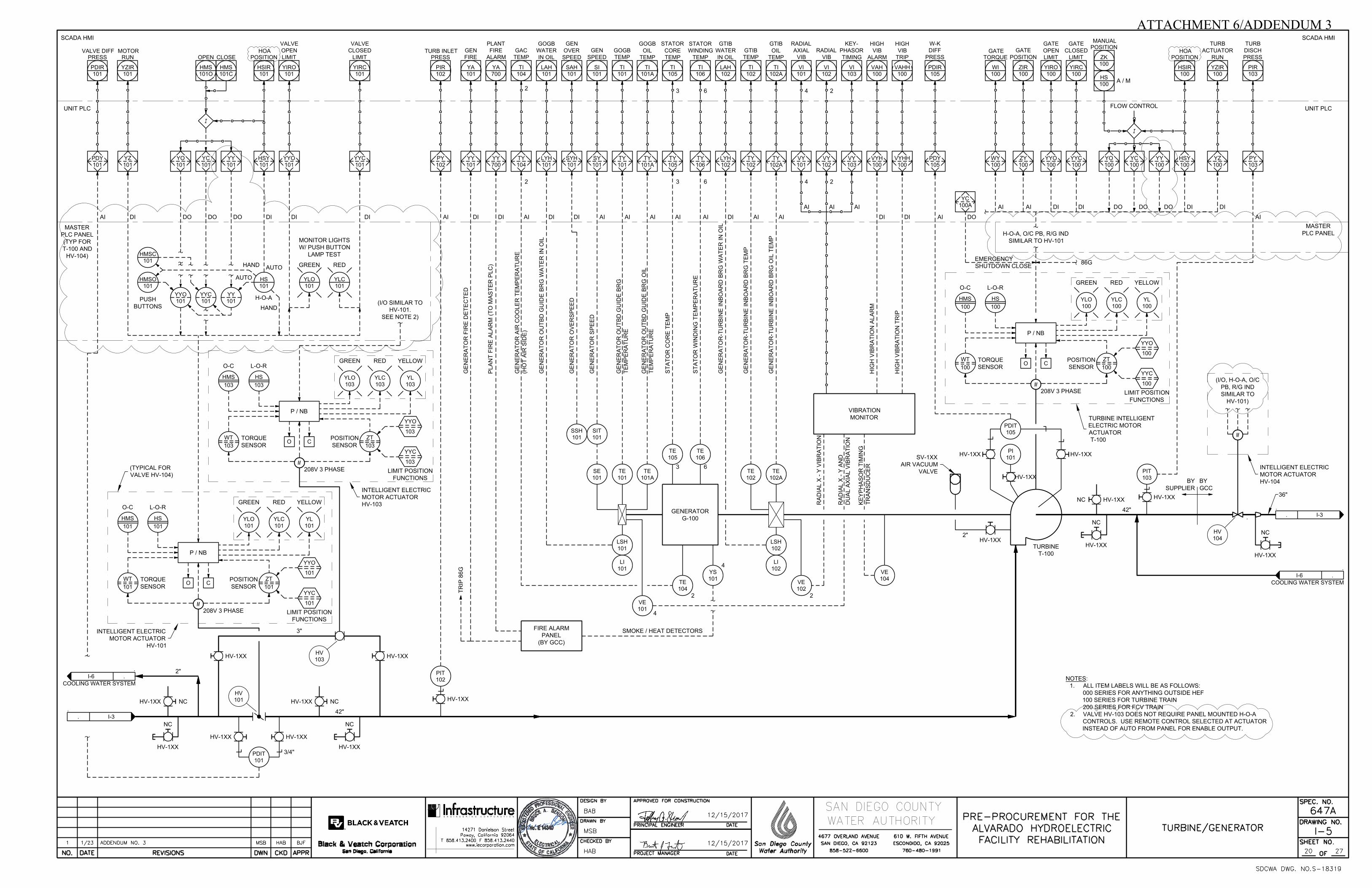
UNIT PLC
SCADA HMI
.
.
I-3
.
.
I-3
PIT
103
PI
101
PDIT
101
PIT
102
.
.
COOLING WATER SYSTEM
I-6
YZIR
101
RUN
MOTOR
HMS
101O
OPEN
HMS
101C
CLOSE
HSIR
101
POSITION
HOA
PDIR
101
PRESS
VALVE DIFF
YIRO
101
YIRC
101
PIR
102
PRESS
TURB INLET
I
42"
3"
YA
101
YA
700
TI
104
LAH
101
SAH
101
SI
101
TI
101
TI
101A
TI
105
TI
106
LAH
102
TI
102
TI
102A
VI
101
VI
102
VI
103
VAH
100
VAHH
100
WI
100
TORQUE
GATE
ZIR
100
YIRO
100
YIRC
100
HS
100
GEN
FIRE
PLANT
FIRE
ALARM
GAC
TEMP
GEN
SPEED
GOGB
TEMP
GTIB
TEMP
RADIAL
VIB
GATE
POSITION
GOGB
WATER
IN OIL
GEN
OVER
SPEED
STATOR
CORE
TEMP
STATOR
WINDING
TEMP
GTIB
WATER
IN OIL
RADIAL
AXIAL
VIB
KEY-
PHASOR
TIMING
HIGH
VIB
ALARM
HIGH
VIB
TRIP
GTIB
OIL
TEMP
GOGB
OIL
TEMP ZK
100
POSITION
MANUAL
HSIR
100
POSITION
HOA
YZIR
100
FLOW CONTROL
I
UNIT PLC
SCADA HMI
A / M
FIRE ALARM
PANEL
(BY GCC)
TR
IP
8
6G
GENERATOR
G-100
SIT
101
SSH
101
TE
105
TE
106
TE
101A
TE
101
SE
101
LSH
101
TE
104
YS
101
VE
101
TE
102A
TE
102
LSH
102
VE
102
VIBRATION
MONITOR
VE
104
86G
42"
.
.
COOLING WATER SYSTEM
I-6
36"
SMOKE / HEAT DETECTORS
GE
NE
RA
TO
R F
IR
E D
ET
EC
TE
D
PL
AN
T F
IR
E A
LA
RM
(T
O M
AS
TE
R P
LC
)
GE
NE
RA
TO
R A
IR
C
OO
LE
R T
EM
PE
RA
TU
RE
(H
OT
A
IR
S
ID
E)
GE
NE
RA
TO
R O
UT
BD
G
UID
E B
RG
W
AT
ER
IN
O
IL
GE
NE
RA
TO
R O
VE
RS
PE
ED
GE
NE
RA
TO
R S
PE
ED
GE
NE
RA
TO
R O
UT
BD
G
UID
E B
RG
TE
MP
ER
AT
UR
E
GE
NE
RA
TO
R O
UT
BD
G
UID
E B
RG
O
IL
TE
MP
ER
AT
UR
E
ST
AT
OR
C
OR
E T
EM
P
ST
AT
OR
W
IN
DIN
G T
EM
PE
RA
TU
RE
GE
NE
RA
TO
R-T
UR
BIN
E IN
BO
AR
D B
RG
W
AT
ER
IN
O
IL
GE
NE
RA
TO
R-T
UR
BIN
E IN
BO
AR
D B
RG
T
EM
P
GE
NE
RA
TO
R-T
UR
BIN
E IN
BO
AR
D B
RG
O
IL
T
EM
P
HIG
H V
IB
RA
TIO
N A
LA
RM
HIG
H V
IB
RA
TIO
N T
RIP
EMERGENCY
SHUTDOWN CLOSE
RA
DIA
L X
- Y
V
IB
RA
TIO
N
RA
DIA
L X
- Y
A
ND
DU
AL
A
XIA
L V
IB
RA
TIO
N
KE
YP
HA
SO
R T
IM
IN
G
TR
AN
SD
UC
ER
3 6
4
2
4
2
2
2
3
3
6
6
4
4
2
2
TURBINE
T-100
NOTES:
1. ALL ITEM LABELS WILL BE AS FOLLOWS:
000 SERIES FOR ANYTHING OUTSIDE HEF
100 SERIES FOR TURBINE TRAIN
200 SERIES FOR FCV TRAIN
2. VALVE HV-103 DOES NOT REQUIRE PANEL MOUNTED H-O-A
CONTROLS. USE REMOTE CONTROL SELECTED AT ACTUATOR
INSTEAD OF AUTO FROM PANEL FOR ENABLE OUTPUT.
HV-1XX HV-1XX
HV-1XXHV-1XX
HV-1XX
HV-1XX
.
HV-1XX
2"
SV-1XX
AIR VACUUM
VALVE
BY
SUPPLIER
BY
GCC
3/4"
HV-1XX
NC
HV-1XX
NC
HV-1XX
NC
HV-1XX
NC
HV-1XX NC HV-1XX NC
HV-1XXNC
HV-1XX
PDIT
105
(I/O, H-O-A, O/C
PB, R/G IND
SIMILAR TO
HV-101)
M
PDIR
105
W-K
DIFF
PRESS
P / NB
O C
ZT
101
POSITION
SENSOR
YYO
YYC
101
YLO
101
YLC
101
YL
GREEN RED YELLOW
WT
101
TORQUE
SENSOR
O-C L-O-R
LIMIT POSITION
FUNCTIONS
M
101
101
INTELLIGENT ELECTRIC
MOTOR ACTUATOR
HV-101
HMS
101
HS
101
P / NB
O C
ZT
103
POSITION
SENSOR
YYO
YYC
103
YLO
103
YLC
103
YL
GREEN RED YELLOW
WT
103
TORQUE
SENSOR
O-C L-O-R
LIMIT POSITION
FUNCTIONS
M
103
103
INTELLIGENT ELECTRIC
MOTOR ACTUATOR
HV-103
HMS
103
HS
103
(I/O SIMILAR TO
HV-101.
SEE NOTE 2)
VALVE
OPEN
LIMIT
VALVE
CLOSED
LIMIT
GATE
OPEN
LIMIT
GATE
CLOSED
LIMIT
PIR
103
TURB
DISCH
PRESS
PY
102
YY
101
YY
700
TY
104
LYH
101
SYH
101
SY
101
TY
101
TY
101A
TY
105
TY
106
LYH
102
TY
102
TY
102A
VY
101
VY
102
VY
103
VYH
100
VYHH
100
PDY
105
WY
100
ZY
100
YYO
100
YYC
100
YC
100
HSY
100
YZ
100
YC
100A
PDY
101
YZ
101
YO
101
YC
101
HSY
101
YYO
101
YYC
101
PY
103
AI AI AI AI AI AI AI AI
AI AI AI
AI
AI AI
AIDI DI DI DI DI DI DI DI AI DI AI DI DI
DI DI DI DIDO
DODODO
P / NB
O C
ZT
100
POSITION
SENSOR
YYO
YYC
100
YLO
100
YLC
100
YL
GREEN RED YELLOW
WT
100
TORQUE
SENSOR
O-C L-O-R
LIMIT POSITION
FUNCTIONS
M
100
100
TURBINE INTELLIGENT
ELECTRIC MOTOR
ACTUATOR
T-100
HMS
100
HS
100
(TYPICAL FOR
VALVE HV-104)
208V 3 PHASE
208V 3 PHASE
208V 3 PHASE
HV
103
HV
101
HV-1XXHV-1XX
HV
104
INTELLIGENT ELECTRIC
MOTOR ACTUATOR
HV-104
TURB
ACTUATOR
RUN
2"
LI
101
LI
102
YO
100
DO
YY
100
DO
H-O-A, O/C PB, R/G IND
SIMILAR TO HV-101
MASTER
PLC PANEL
YYO
101
YYC
101
YY
101
HMSO
101
HMSC
101
HS
101
YLO
101
YLC
101
H-O-A
PUSH
BUTTONS
GREEN RED
MONITOR LIGHTS
W/ PUSH BUTTON
LAMP TEST
AUTO
AUTO
HAND
MASTER
PLC PANEL
(TYP FOR
T-100 AND
HV-104)
YY
101
DO
HAND
E N G I N E E R I N G C O R P O R A T I O N
ATTACHMENT 6/ADDENDUM 3
UNIT PLC
SCADA HMI
UNIT PLC
SCADA HMI
.
.
I-5
1" DRAIN
PDSH
111
PDSHH
111
2" DRAIN
I
111
PDAH
YC
111
HS
111B
2" 2"
2" BY-PASS
AUTO FLUSHING STRAINER
W/ PRESSURE DIFFERENTIAL
ALARM
FLUSH
OUTLET
STR-111
NC
NC
HIGH DIFF.
PRESSURE
AMBER
TIMER
MANUAL
FLUSH
STRAINER
LOCAL CONTROL PANEL
TI
121
PIT
121
.
.
I-5
.
1"
HV-1XX
1"
GENERATOR-TURBINE
INBOARD BEARING
COOLER
1"
1"
GENERATOR
AIR HOUSING
COOLER
.
1"
HV-1XX
1"
GENERATOR
OUTBOARD
BEARING COOLER
2"
2"
NOTES:
1. EQUIPMENT, INSTRUMENTATION, AND PIPE SIZES SHOWN ARE
BASED ON ESTIMATES. SUPPLIER SHALL SIZE AND FURNISH EACH
ITEM AND PROVIDE SUPPORTING CALCULATIONS TO MEET
COOLING WATER SYSTEM REQUIREMENTS.
2. ALL MECHANICAL EQUIPMENT, VALVES, INSTRUMENTS AND
PIPING SHOWN ON THIS SHEET BY SUPPLIER.
PDAH
111
HIGH
STRAINER
DIFF. PRESSURE HMS
121O
OPEN
HS
121
HMS
121C
CLOSE
A / M
PIR
121
COOLING
WATER
PRESSURE
FIR
101
FIR
103
FIR
102
GE
N O
UT
BD
G
UID
E B
RG
CL
G W
TR
F
LO
W
GE
N A
IR
C
OO
LE
R
CL
G W
TR
F
LO
W
GE
N/T
UR
IN
BO
AR
D
BR
G C
LG
W
TR
F
LO
W
IGENERATOR
START / STOP
SEQUENCE
HSIR
121
YIRO
121
YIRC
121
VALVE
CLOSED
LIMIT
VALVE
OPEN
LIMIT
REMOTE
STATUS
HV-1XX
HV-1XX
HV-1XX
PI
111
HV-1XX HV-1XX HV-1XX
HV-1XX
HV-1XX
HV-1XX
HV-1XX
2"
TI
101
TI
103
TI
102
.
HV-1XX
HV-1XX
HV-1XX
HV-1XX
PDIT
104
PI
104
HV-1XX
PDIR
104
FIR
104
HV-1XX
HV-1XX HV-1XX
FLT-104B
1"
NC
TURBINE
SHAFT
SEAL
SHAFT SEAL
WATER FILTER
DIFF PRESSURE
SHAFT
SEAL
WATER
FLOW RATE
SH
AF
T S
EA
L W
TR
F
LO
W
S
FE
104
FIT
104
FE
101
FIT
101
FE
103
FIT
103
FE
102
FIT
102
P / NB
O C
ZT
121
POSITION
SENSOR
YYO
YYC
121
YLO
121
YLC
121
YL
GREEN RED YELLOW
WT
121
TORQUE
SENSOR
O-C L-O-R
LIMIT POSITION
FUNCTIONS
M
121
121
INTELLIGENT ELECTRIC
MOTOR ACTUATOR
HV-121
HMS
121
HS
121
PDYH
111
YO
121
YC
121
HSY
121
YYO
121
YYC
121
PY
121
PDY
104
FY
104
FY
101
FY
103
FY
102
YZ
121
YZIR
121
RUN
MOTOR
DI DI DI DIDODO
GOGB CW
FLOW
RATE
GAC CW
FLOW
RATE
GTIB CW
FLOW
RATE
DI AI AI AI AI AI AI
HV
121
2" 2"
HV-1XX
HV-1XX
STR-1XX
FLT-104A
YY
121
DO
E N G I N E E R I N G C O R P O R A T I O N
ATTACHMENT 7/ADDENDUM 3

NOTES:
1. EACH PANEL SHALL BE NEMA 12 ENCLOSURE 90"H X 20"D X WIDTH AS NOTED.
2. GENERAL FRONT PANEL LAYOUTS SHOWN TO SIZE PANELS. SUPPLIER SHALL
SUBMIT DETAILED PANEL INTERIOR AND EXTERIOR LAYOUTS.
3. TYPICAL VALVE CONTROL DEVICES: GREEN OPEN AND RED CLOSED
INDICATING LIGHTS, GREEN OPEN AND RED CLOSE PUSHBUTTONS,
MAINTAINED HAND-OFF-AUTO SWITCH. ALL DEVICES SHALL BE PROVIDED
WITH LEGENDS.
E N G I N E E R I N G C O R P O R A T I O N
ATTACHMENT 8/ADDENDUM 3

ATTACHMENT 9/ADDENDUM 3
Question Answer
1 How is SCOOP content valued in bid evaluation? See Contract Documents, Notice Inviting Bids, Section 3, and Instructions to Bidders, Section 3.0. Schedule A‐1, Designation of All Subcontractors, including Subcontractors/Vendors/Service Providers is to be completed and submitted as part of bid.
2 Is there a possibility to provide a lower voltage system, maybe at 480V or 2400V, with a GSU transformer to provide additional generator protection?
Provide 12kV generator per the Contract Documents. See Addendum 3 for allowable alternate grounding methods.
3 Section 11200, Turbine, Part 2.02, Paragraph A. The old IEC 193 1965 Edition contained an Amendment 1, but the current IEC 60193 does not contain an Amendment 1. Can you please clarify?
See Addendum 3 for updated standard references.
4 Section 11200, Turbine, Part 1.07, Paragraph C, Item 4. Can you please explain the significance of the “Existing conditions” and “FRS II conditions”? Additionally, is the turbine expected to operate down to heads as low as 150 feet?
The upstream headwater elevation will permanently change in the near future as a result of another project named "FRS II." The two hydraulic conditions in Section 11200, Turbine, Part 1.07, Paragraph C, Item 4 represent the current conditions and future conditions. The turbine is required to operate within the conditions defined in the Contract Documents.
5 Section 01640, Supplier's Services, Part 1.01, Paragraph A. IEC 60041 is not applicable to small hydro and IEC 62006 should be used for machines with unit power up to about 15 MW and reference diameter of about 3 m. Can you please confirm or clarify which standard we are to work to?
See Addendum 3 for updated standard references.
6 Section 01640, Supplier's Services, Part 1.06, Paragraph A states “The General Construction Contractor will direct and perform start up and commissioning for all systems for the Project. The General Construction Contractor will provide or coordinate the equipment and labor to perform field tests required to validate the performance of the supplier equipment.”IEC 60041 states:4.3 Personnel ‐ The selection of personnel to conduct the test and procedures in connection therewith are matters of prime importance.4.3.1 Chief of test ‐ A Chief of test shall be appointed by agreement between the two parties. He should be competent to supervise all of the calibrations, measurements and calculations necessary to determine the performance of the machine. He shall exercise authority over all observers. He shall supervise the conduct of the test in accordance with this standard and any written agreement made prior to the test by the contracting parties. He shall be responsible for the calibration of all test instruments and for all test measurements. He shall report on test conditions and be responsible for the computation of results including the determination of the measurement uncertainties and the preparation of the final report On any question pertaining to the test his decision, subject to the provisions of 4.5.1,4.7.6 and 4.9.1, shall be final.4.3.2 Choice of personnel ‐ The testing team shall have the necessary competence and experience for the correct installation and utilization of the measuring equipment.“The two parties” refer to the supplier and the purchaser. How does the supplier ensure that the General Contractor will provide suitably qualified labor?
Refer to Section 01640, Supplier's Services, Part 1.04 for Supplier's responsibilities including providing staff to witness and validate the General Construction Contractor's installation and testing. Section 01640, Supplier's Services, Part 1.04 includes requirements to notify the Engineer in writing if work is being performed contrary to Supplier's instructions.
7 Section 01640, Supplier's Services, Part 1.06, Paragraph E. Could you please explain the proposed method of flow measurement, as the drawings provided in Alvarado Pre‐Procurement Bid Set.pdf do not show any suitable location for accurate flow measurement in accordance with IEC 60041?
The General Construction Contractor will install a Venturi flow meter upstream of the turbine that will be used for testing. Refer to Drawing I‐3 which identifies this meter as instrument FE‐001.
Questions and Answers - Pre-Procurement for Alvarado Hydroelectric Facility Rehabilitation, Spec 647A
Q0333.010.2 - Questions and Answers.XLSX

ATTACHMENT 9/ADDENDUM 3
Question Answer
8 Section 16210, Generator, Part 1.04, Paragraph A. NEMA MG 5.1 was withdrawn in 1982. Please advise which alternative standard is to be used for runout checks?
See Addendum 3 for updated standard references.
9 Section 16210, Generator, Part 1.04, Paragraph B. IEEE 85 was withdrawn in 1980. Please advise which alternative standard to be used?
IEEE published no replacement. Use IEEE 85.
10 Section 16210, Generator, Part 1.03, Paragraph B. Can you please advise if an air‐cooled generator to IP21 or IP23 would be acceptable?
No that is not acceptable.
11 Section 16210, Generator, Part 1.03, Paragraph C. Would a lower voltage generator plus a GSU transformer be acceptable to propose?
No.
12 Section 16210, Generator, Part 1.04, Paragraph B. ANSI C50.12 is typically applied for generators over 5 MVA. Can you please advise which specification we should follow for this project?
Follow IEEE/ANSI C50.12 per the Contract Documents.
13 Section 16210, Generator, Part 1.04, Paragraph D. This is not a common standard to reference for rotating electrical machines. Can you please advise the intent of this line item and how it will be implemented and to which standard?
Follow IEC 994 per the Contract Documents.
14 Section 16210, Generator, Part 1.04, Paragraph E. Can you please advise if a plain shaft end with key will be acceptable to propose?
Yes. See Addendum 3.
15 Section 16210, Generator, Part 1.05, Paragraph C. Our calculations are performed by engineers that typically do not hold Professional Engineer licenses in the USA. Will professionally licensed/certified engineers from other jurisdictions be recognized?
Calculations must be performed by a registered professional engineer. See Addendum 3.
16 Section 16210, Generator, Part 1.05, Paragraph D. Our calculations are performed by engineers that typically do not hold Professional Engineer licenses in the USA. Will professionally licensed/certified engineers from other jurisdictions be recognized?
Calculations must be performed by a registered professional engineer. See Addendum 3.
17 Section 16210, Generator, Part 1.05, Paragraph E. Our calculations are performed by engineers that do not hold Structural Engineer licenses in the State of California. Will professionally licensed/certified engineers from other jurisdictions be recognized?
No, calculations must be performed by a registered structural engineer in the State of California.
18 Section 16210, Generator, Part 1.06, Paragraph A, Item 5. Can you please clarify what is required and whether or not a smaller range will be acceptable?
See Addendum 3 for updated requirements.
19 Section 16210, Generator, Part 1.06, Paragraph B, Item 1. Will a bearing solution utilizing anti‐friction roller bearings be acceptable for this smaller kW generator?
No. See Addendum 3.
20 Section 16210, Generator, Part 1.06, Paragraph C, Item 1. This is not a common standard to reference for rotating electrical machines. Can you please explain the intent of this line item?
Follow IEC 994 per the Contract Documents.
21 Section 16210, Generator, Part 2.02, Paragraph B, Item 1. Please advise if a cylindrical rotor construction would be acceptable to propose?
No.
22 Section 16210, Generator, Part 2.02, Paragraph B, Item 7. Would it be acceptable for the generator manufacturer to suggest an alternate first critical speed for review by the owner/consultant?
No.
23 Section 16210, Generator, Part 2.02, Paragraph C, Item 1. Can you please advise if a plain shaft end with key will be acceptable to propose?
Yes. See Addendum 3.
24 Section 16210, Generator, Part 2.02, Paragraph C, Item 2. It is wholly impractical to receive the turbine’s runner and spiral case, construct a suitable foundation, and couple the generator and turbine runner at our shop and conduct a system runout check. Also, as described above, NEMA MG5.1 was withdrawn in 1982. We request this be removed from the specification.
No. See Addendum 3 for updated requirements.
25 Section 16210, Generator, Part 2.02, Paragraph D, Items 3 and 6. Will a bearing solution utilizing anti‐friction roller bearings be acceptable for this smaller kW generator?
No. See Addendum 3 for updated requirements.
26 Section 16210, Generator, Part 2.04, Paragraph A, Item 1, Subitem a. Can you please advise the need for core RTDs and also whether or not it will be acceptable to remove this from the scope?
No provide per Contract Documents.
Q0333.010.2 - Questions and Answers.XLSX

ATTACHMENT 9/ADDENDUM 3
Question Answer
27 Section 16210, Generator, Part 2.04, Paragraph A, Items 5 and 6. Can you please advise the need for smoke and heat detectors and also whether or not it will be acceptable to remove this from the scope? If they are necessary, can we please request clarification on the manufacturer and model of detectors desired?
No provide per Contract Documents.
28 Section 16210, Generator, Part 2.04, Paragraph D, Item 1. Would heaters with an amperage of 120V be acceptable? Additionally, as this is a small generator we would not recommend providing adjustable space heaters – please advise if this will be acceptable?
See Addendum 3 for updated requirements. Provide adjustable heaters per the Contract Documents.
29 Turbine/Generator – Guaranteed Performance Worksheet ‐ The Net Head column does not equal the “Net Head Water Elevation” column minus the “Tailwater Elevation” column at flows of 50, 80 and 100 cfs because of a rounding error. As it is an important part of the supplier evaluation, can you please clarify the exact values you would like us to use for the performance guarantees?
See Addendum 3 for updated worksheet.
30 Section 16345, Medium‐Voltage Vacuum Interrupter Switchgear, Part 1.03. Can the type of switchgear be confirmed as metal‐enclosed, metalclad, or metalclad arc‐resistant along with the applicable IEEE/ANSI standards be provided?
Provide metalclad per Section 16345, Medium‐Voltage Vacuum Interrupter Switchgear, Part 2.03, Paragraph A. See Addendum 3 for applicable references.
31 Section 16345, Medium‐Voltage Vacuum Interrupter Switchgear, Parts 2.01. Is it acceptable to the Water Authority that the utility metering section be manufactured by others than those listed?
No.
32 Section 16345, Medium‐Voltage Vacuum Interrupter Switchgear, Part 2.02. Is it acceptable to the Water Authority that the NEMA 3R enclosures be manufactured by others than those listed?
No.
33 Section 16345, Medium‐Voltage Vacuum Interrupter Switchgear, Part 2.02, Paragraph A states “The switchgear shall be the product of a manufacturer of both the stationary and draw out elements of a complete power circuit breaker assembly.” Please clarify the intent of this statement. Is the entire switchgear assembly including enclosures to be the manufacture of Eaton, GE or Schneider/SquareD? Or can the circuit breaker units and draw‐out cradle assemblies to be of manufacture by Eaton, GE or Schneider/SquareD while the balance of the assembly manufactured by custom switchgear manufacturers?
The entire switchgear assembly, including enclosures, shall be from by the same manufacturer. See Addendum 3.
34 Section 16910, Programmable Logic Controller, Part 1.05.. Please confirm the terms relating to the manufacturer of the PLC hardware and software. Does the term “manufacturer” apply to the manufacturer of the PLC hardware and software? Or does this term apply to the system integrator that provides the electrical engineering services for the integration, PLC control programming, protective relay integration and programming, and other electrical equipment relating to the overall turbine/generator and auxiliary equipment?
The term manufacturer applies to the ControlLogix PLC hardware, not the system integrator.
35 Section 16910, Programmable Logic Controller, Part 1.06 states “programming and troubleshooting through telephone consultation and on‐site support. This support shall be available during normal Water Authority working hours between 6:00 a.m. and 4:30 p.m., Monday through Thursday.” Please clarify the time constraints for this requirement. When is this requirement required to start and terminate? For example will the availability of this service begin during the dry testing phase and then terminate at the completion of commissioning?
See Addendum 3 for updated requirements. This requirement applies to the manufacturer of the ControlLogix PLC hardware.
Q0333.010.2 - Questions and Answers.XLSX

ATTACHMENT 9/ADDENDUM 3
Question Answer
36 Section 16910, Programmable Logic Controller, Part 1.06, Paragraph C states “The manufacturer shall have a field service department staffed with experienced representatives stationed within San Diego County with the capability of providing on‐site support. This support shall be available seven days a week and 24 hours per day with a two‐hour minimum call back and be on‐site within four hours after the first initial phone call. All hardware components used by the Water Authority shall be available and in stock in San Diego County seven days a week, 24 hours per day.” Please confirm who this requirement is intended to apply to. Does this requirement apply to the PLC hardware and software manufacturer (in this case specified to be Rockwell/Allen‐Bradley)? Or does this requirement apply to the engineering service provider that integrates the protection and control system as noted above?
The term manufacturer applies to the ControlLogix PLC hardware, not the system integrator.
37 Section 16910, Programmable Logic Controller, Part 2.01, Paragraph B. In this item of the specification, redundancy is mentioned. The network diagram I‐2 shows redundant CPU’s for the “Master PLC.” Please confirm that the only redundancy requirement is for the Master PLC – CPU’s and no other redundancy is required in the Master or Unit Control PLC systems.
The Master PLC shall have redundant CPUs as shown on I‐2. The Unit PLC does not require redundant CPUs as shown on I‐2. Provide redundant power supplies as specified in Section 16910, Programmable Logic Controller, Part 2.03, Paragraph D, and as shown on I‐9.
38 Section 16910, Programmable Logic Controller, Part 2.05, Paragraph D, Item 4. Please provide the clarification of the time stamping requirement. For example is this to be for sequence of events recording or similar? How will the time be standardized i.e. a satellite clock? What is the timing resolution for the stamping? And please provide the intent and when the time stamps are to occur? Also how the time stamped events are to be stored?
Per Section 16910, Programmable Logic Controller, Part 2.05, Paragraph D, Item 4, Input/Output modules shall support time stamping of data. No time stamping function is required in the Unit PLC.
39 Section 16910, Programmable Logic Controller, Part 2.10, Paragraph C. Please confirm who this additional warranty requirement applies to. Does this requirement apply to the PLC hardware and software manufacturer (in this case specified to be Rockwell/Allen‐Bradley)? Or does this requirement apply to the engineering service provider that integrates the protection and control system as noted above?
See Addendum 3 for updated requirements.
40 Section 16161, Control Panels, Part 2.01. How is the protection and control panel location in this plant to be classified? From the drawings the protection and control panels appear to be below grade.
PLC panel enclosures are NEMA 12 per I‐8 and E‐9.
41 Section 16161, Control Panels, Part 3.01. Please confirm that UL509 is acceptable for the panel approval. No, UL509 is not acceptable. See Addendum 3 for updated requirements.
42 Section 11200, Turbine, Part 2.05, Paragraph B. May we please request that the interior surfaces of the turbine, penstock, and draft tube be painted with System No. 7 from Section 09901, Painting and Coating, Part 2.02, Paragraph A?
No.
43 Section 16161, Control Panels, Part 2.02, Paragrah E states “Except for stainless steel enclosures, paint the interior with two coats of white gloss enamel.” Typically the enclosure body internal and external are painted the same color at the same time. Would it be acceptable to propose provide subpanels that are powder coated white with ANSI 61 gray painted interior of the enclosure body?
See Addendum 3 for updated requirements.
44 Section 16161, Control Panels, Part 2.02, Paragraph H, Item 8 and Drawing I‐12. Please clarify the discrepancy of the receptacle model: Triplite Isobar‐4 vs Phoenix Contact EM‐DOU‐120/20.
Drawing I‐12 represents typical control panel wiring. The Phoenix Contact EM‐DOU‐120/20 is part of the typical fixture terminal assembly. The Receptacle Surge Suppressor in Section 16161, Part 2.02, Paragraph H, Item 8 supports peripheral system equipment power supplies with cord type plugs.
Q0333.010.2 - Questions and Answers.XLSX
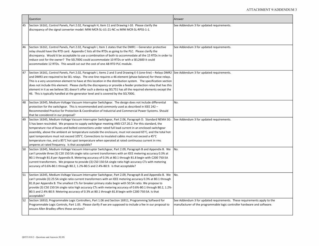
ATTACHMENT 9/ADDENDUM 3
Question Answer
45 Section 16161, Control Panels, Part 2.02, Paragraph H, Item 11 and Drawing I‐10. Please clarify the discrepancy of the signal converter model: MINI MCR‐SL‐U1‐21‐NC vs MINI MCR‐SL‐RPSS‐1‐1.
See Addendum 3 for updated requirements.
46 Section 16161, Control Panels, Part 2.02, Paragraph I, Item 1 states that the DMR1 – Generator protective relay should have the RTD card. Appendix C lists all the RTDs as going to the PLC. Please clarify the discrepancy. Would it be acceptable to use a combination of both to accommodate all the 15 RTDs in order to reduce cost for the owner? The SEL700G could accommodate 10 RTDs or with a SEL2600 it could accommodate 12 RTDs. This would cut out the cost of one AB RTD PLC module.
See Addendum 3 for updated requirements.
47 Section 16161, Control Panels, Part 2.02, Paragraph I, Items 2 and 3 and Drawing E‐5 (one‐line) – Relays DMR2 and DMR3 are required to be SEL relays. The one‐line requires a 46 element (phase balance) for these relays. This is a very uncommon element to have at this location in the distribution system. The specification section does not include this element. Please clarify the discrepancy or provide a feeder protection relay that has this element in it as we believe SEL doesn’t offer such a device eg SEL751 has all the required elements except the 46. This is typically handled at the generator level and is covered by the SEL700G.
See Addendum 3 for updated requirements.
48 Section 16345, Medium‐Voltage Vacuum Interrupter Switchgear. The design does not include differential protection for the switchgear. This is recommended and commonly used as described in IEEE 242 – Recommended Practice for Protection & Coordination of Industrial and Commercial Power Systems. Should that be considered in our proposal?
No.
49 Section 16345, Medium‐Voltage Vacuum Interrupter Switchgear, Part 2.06, Paragraph D. Standard NEMA SG‐5 has been rescinded. We propose to supply switchgear meeting ANSI C37.20.2. Per this standard, the temperature rise of buses and bolted connections under rated full load current in an enclosed switchgear assembly, above the ambient air temperature outside the enclosure, must not exceed 65°C, and the total hot spot temperature must not exceed 105°C. Connections to insulated cables must not exceed a 45°C temperature rise, and a 85°C hot spot temperature when operated at rated continuous current in rms amperes at rated frequency. Is that acceptable?
See Addendum 3 for updated requirements.
50 Section 16345, Medium‐Voltage Vacuum Interrupter Switchgear, Part 2.09, Paragraph B and Appendix B. We can’t provide three (3) C20 150:5A single ratio current transformers with an IEEE metering accuracy 0.3% at B0.1 through B1.8 per Appendix B. Metering accuracy of 0.3% at B0.1 through B1.8 begin with C200 750:5A current transformers. We propose to provide (3) C50 150:5A single ratio high accuracy CTs with metering accuracy of 0.6%‐B0.1 through B0.2, 1.2%‐B0.5 and 2.4%‐B0.9. Is that acceptable?
No.
51 Section 16345, Medium‐Voltage Vacuum Interrupter Switchgear, Part 2.09, Paragraph B and Appendix B. We can’t provide (3) 25:5A single ratio current transformers with an IEEE metering accuracy 0.3% at B0.1 through B1.8 per Appendix B. The smallest CTs for breaker primary stabs begin with 50:5A ratio. We propose to provide (3) C50 150:5A single ratio high accuracy CTs with metering accuracy of 0.6%‐B0.1 through B0.2, 1.2%‐B0.5 and 2.4%‐B0.9. Metering accuracy of 0.3% at B0.1 through B1.8 begin with C200 750:5A. Is that acceptable?
No.
52 Section 16910, Programmable Logic Controllers, Part 1.06 and Section 16911, Programming Softward for Programmable Logic Controls, Part 1.05. Please clarify if we are supposed to include a fee in our proposal to ensure Allen Bradley offers these services?
See Addendum 3 for updated requirements. These requirements apply to the manufacturer of the programmable logic controller hardware and software.
Q0333.010.2 - Questions and Answers.XLSX

ATTACHMENT 9/ADDENDUM 3
Question Answer
53 Appendix C and Drawings I‐3 to I‐6 and I‐12. Drawing I‐12 shows an “Enable” digital output for the valve control. Appendix C does not list this as a digital output nor is it shown on drawings I‐3 to I‐6. Please address the discrepancy and clarify if the “Enable” DO and associated interposing relays are supposed to be included.
See Addendum 3 for updated requirements.
54 Are the vibration probes themselves, listed on the Instrumentation List as VE‐101A, VE‐101B, VE‐101C, VE‐101D, VE‐102A, VE‐102B, supplied by the generator manufacter installed in the generator or the controls contractor for installation in the field?
Furnish and install vibration probes in accordance with Specification 16210, Generator.
55 After reviewing terms of the request for proposal, can the Water Authority waive the requirement to have equipment in the USA? Our equipment is manufacturered in Brazil, but to date we have no installations in the USA.
No.
56 Will it be possible to provide a further extension to the bid deadline? Switchgear suppliers named in the Contract Documents are advising they need more time to comply with the requirements. We request the bid deadline be extended until February 16, 2018.
No.
Q0333.010.2 - Questions and Answers.XLSX


