24
Translation of the Original Manual Control Unit KEH-P / Force-1.DIN Assembly and Operating Manual Superior Clamping and Gripping
Translation of the Original Manual
Control Unit
KEH-P / Force-1.DIN
Assembly and Operating Manual
Superior Clamping and Gripping
Translation of the Original Manual
Imprint:
Copyright:
This manual remains the copyrighted property of SCHUNK GmbH & Co. KG. It is solely
supplied to our customers and operators of our products and forms part of the unit. This
documentation may not be duplicated or made accessible to third parties, in particular
competitive companies, without our prior permission.
Technical changes:
We reserve the right to make alterations for the purpose of technical improvement.
Document number:
Edition: 3.0 |March 14, 2014|en
© SCHUNK GmbH & Co. KG, Lauffen/Neckar
All rights reserved
Dear customer,
congratulation on choosing a SCHUNK product. By choosing SCHUNK, you have opted
for the highest precision, top quality and best service.
You are going to increase the process reliability of your production and achieve best
machining results – to the customer's complete satisfaction.
SCHUNK products are inspiring.
Our detailed assembly and operation manual will support you.
Do you have further questions? You may contact us at any time – even after purchase.
Kindest Regards
Yours SCHUNK GmbH & Co. KG
Precision Workholding Systems
Bahnhofstr. 106 – 134
D-74348 Lauffen/Neckar
Tel. +49-7133-103-2503
Fax +49-7133-103-2189
www.schunk.com
QM.UC.00002-R3.0 |en

Table of contents
QM.UC.00002-R3.0 |en 3
Table of contents
1 About this manual .................................................................................................... 4
1.1 Warnings ................................................................................................................... 4
1.1.1 Signal words .................................................................................................. 4
1.1.2 Symbols ......................................................................................................... 4
2 Basic safety notes .................................................................................................... 5
2.1 Intended use ............................................................................................................. 5
2.2 Environmental and operating conditions ................................................................. 5
2.3 Product safety........................................................................................................... 6
2.3.1 Protective equipment ................................................................................... 6
2.4 Personnel qualification ............................................................................................. 6
2.5 Use of personal protective equipment .................................................................... 7
2.6 Notes on particular risks ........................................................................................... 7
3 Warranty .................................................................................................................. 8
4 Scope of delivery ...................................................................................................... 9
5 Technical Data ......................................................................................................... 10
5.1 Identification plate ................................................................................................. 11
5.2 Dimensions ............................................................................................................. 12
6 Installation .............................................................................................................. 14
7 Initial commissioning and normal operation ............................................................ 16
7.1 Initial commissioning .............................................................................................. 16
7.2 Normal operation ................................................................................................... 18
8 Troubleshooting ...................................................................................................... 20
9 Servicing and maintenance ...................................................................................... 21
10 Storage .................................................................................................................... 22
11 Disposal .................................................................................................................. 23
12 Spare parts .............................................................................................................. 24

About this manual
4 QM.UC.00002-R3.0 |en
About this manual
This instruction is an integral part of the product and contains im-
portant information for a safe and proper installation, commis-
sioning, operation, maintenance and helps for an easier trouble
shooting.
Before using the product, read and note the instruction, especially
the chapter "Basic safety notes".
Warnings
The following signal words and symbols are used to highlight dan-
gers.
Signal words
DANGER Dangers for persons.
Non-compliance will inevitably cause irreversible injury or death.
WARNING Dangers for persons.
Non-compliance may cause irreversible injury or death.
CAUTION Dangers for persons.
Non-observance may cause minor injuries.
ATTENTION Information about avoiding material damage
Symbols
Warning about a danger point
Warning about dangerous electrical voltage
Danger of magnetic field
Danger of falling down workpieces
General mandatory sign to prevent material damage
1
1.1
1.1.1
1.1.2
Basic safety notes
QM.UC.00002-R3.0 |en 5
Basic safety notes
Intended use
This control unit has exclusively been designed for the operation of
SCHUNK electro-permanent magnetic chucks, during the use of
which it is essential, that the time between two ON/OFF cycles is
not less than 3 minutes.
This control unit has furthermore been designed for the installa-
tion inside the electrical cabinet of machine tools for the clamping
and machining of workpieces and must operate in dry interiors
with a relative air humidity of 5-15 % (max. 50% at 40°, without
condensation) and an ambient temperature of 5°-40°C.
The requirements of the applicable standards must be observed.
The control unit may only be used in the context of its defined ap-
plication parameters.
For its intended use it is also essential to observe the technical da-
ta, the installation and operation notes as well as the maintenance
intervals indicated in the present manual.
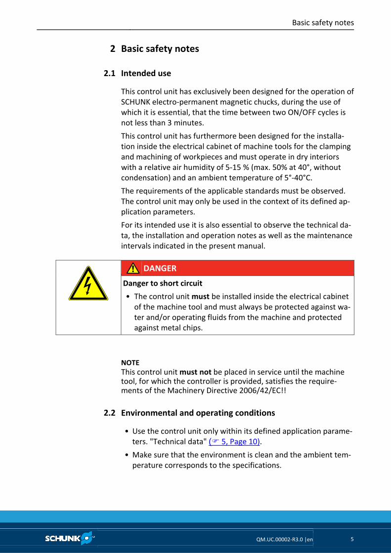
DANGER
Danger to short circuit
• The control unit must be installed inside the electrical cabinet
of the machine tool and must always be protected against wa-
ter and/or operating fluids from the machine and protected
against metal chips.
NOTE
This control unit must not be placed in service until the machine tool, for which the controller is provided, satisfies the require-ments of the Machinery Directive 2006/42/EC!!
Environmental and operating conditions
• Use the control unit only within its defined application parame-
ters. "Technical data" (� 5, Page 10).
• Make sure that the environment is clean and the ambient tem-
perature corresponds to the specifications.
2
2.1
2.2

Basic safety notes
6 QM.UC.00002-R3.0 |en
Product safety
Dangers arise from the control unit, if e.g.:
• the control unit is not used in accordance with its intended
purpose.
• the control unit has not been installed or maintained properly.
• the safety and installation notes have not been observed.
Avoid any manner of working that may interfere with the function
and operational safety of the control unit.
Wear protective equipment.
NOTE
More information is contained in the relevant chapters.
Protective equipment
Provide safety devices according to the EC Machinery Directive.
Personnel qualification
Installation, first commissioning, maintenance, and repair of the
control unit may be performed by trained qualified personnel, on-
ly. Any person called upon by the operator to work on the control
unit must have read and understood the complete installation and
operating manual especially the chapter "Basic safety notes" (� 2,
Page 5). This applies particularly to personnel used only occasion-
ally, such as maintenance personnel.
2.3
2.3.1
2.4

Basic safety notes
QM.UC.00002-R3.0 |en 7
DANGER
Danger due to a magnetic field.
This control unit always uses a magnetic system. The following
groups of persons must not come into contact with it:
• Persons with pacemakers.
• Persons with metal or electronic prostheses.
• Persons with insulin pumps.
• Persons with muscular stimulation systems.
• Pregnant women.
• These persons should always keep a safe distance of at least
2m to the unit.
Use of personal protective equipment
When using this product, observe the relevant industrial safety
regulations and use the personal protective equipment (PPE) re-
quired!
• Use protective gloves, safety shoes and safety goggles.
• Observe safe distances.
• Minimal safety requirements for the use of equipment.
Notes on particular risks
• Remove the energy supplies before installation, modification,
maintenance, or adjustment work.
• Ensure that no residual energy remains inside the system.
• Perform maintenance, modifications, and additions outside the
danger zone.
• For all work, secure the control unit against accidental opera-
tion.
2.5
2.6
Warranty
8 QM.UC.00002-R3.0 |en
Warranty
The warranty is valid for 12 months from the delivery date to the
production facility under the following conditions:
• Intended use in 1-shift operation
• Observe the mandatory maintenance intervals.
• Observe the environmental and operating conditions.
Parts touching the work piece and wearing parts are not part of
the warranty.
The buyer agrees to send a written detailed report on newly dis-
covered defects of the control unit to SCHUNK within 10 days after
identification.
3
Procedure in the
event of warranty

Scope of delivery
QM.UC.00002-R3.0 |en 9
Scope of delivery
Fig. 1
The scope of delivery includes:
• Control unit
• Remote control (supplied as standard on the KEH-P series, on
request for all other types)
4
Power
adjustment LED
tenza
MAG-LED
MAG-push button
KEY push button
DEMAG push button
DEMAG-LED
Power adjustment
push buttons
LED KEY

Technical Data
10 QM.UC.00002-R3.0 |en
Technical Data
Type FORCE-1.DIN / KEH.P / KEH.R
Mains voltage 200 – 230 – 400 – 460 (VAC)
Frequency 50Hz / 60Hz
Phases 2 + PE
Rated current 32 A
Rated short circuit current 6 kA
Breaking current of the fuse for
the auxiliary cir-cuit
500 mA at 500 V AC
IP rating IP20 regarding the control unit
IP rating of the equipment in which it is installed:
at customer’s care
Activation time >0.3s at cycle 3; < 8s at cycle 8
Activation change 1 (de-) magnetization - max. every 3 min.
Weight ~ 2 kg
Ambient temperature 5° - 55° C
Ambient conditions Operation in dry interiors
with a relative air humidity of approx. 5 - 15%
Protect product from caustic vapors and excessive heat.
5

Technical Data
QM.UC.00002-R3.0 |en 11
Identification plate
The identification plate is placed on the control unit cover:
Fig. 2
Information Description
Id. No. Product code no.
Type Model
Serial No. Product serial no.
Work No. Product production no.
Voltage Rated voltage (mains)
Frequency Rated frequency (mains)
Channels Number of output channels
Phases Phases (mains)
Current Rated current (mains)
Lcm Rated short-circuit data
Year Year of manufacture
Weight Weight
The identification plate must never be removed! Please always
have the serial no. at hand when contacting SCHUNK about tech-
nical matters.
5.1

Technical Data
12 QM.UC.00002-R3.0 |en
Dimensions
Fig. 3 Dimensions FORCE-1.DIN and KEH.R
Fig. 4 Dimensions FORCE-1.DIN.2
5.2
KEH-P01
FORCE-1.DIN
FORCE-1.DIN.1C
KEH.R01
KEH.R02
KEH.R03
KEH-P02
FORCE-1.DIN.2
FORCE-1.DIN.2C

Technical Data
QM.UC.00002-R3.0 |en 13
Fig. 5 Dimensions FORCE-1.DIN.3 and FORCE-1.DIN.4
FORCE-1.DIN.5, FORCE-1.DIN.6, FORCE-1.DIN.7 and FORCE-1.DIN.8
KEH-P03-P08
FORCE-1.DIN.4
FORCE-1.DIN.3C
FORCE-1.DIN.4C

Installation
14 QM.UC.00002-R3.0 |en
Installation
PERICOLO
Danger of electric shock!
Touching live parts can cause death by electric shock.
• All the electrical connections must be carried out by an elec-
trician who has all the relevant information for the job. Al-
ways observe laws, regulations and standards applicable at
the site of installation and operation.
1 Check the packaging before accepting the control unit.
2 Open the packaging and take out the control unit.
3 Check the control unit for transport damage!
4 Compare the control unit with the specifications given in the
order!
DANGER
Danger caused by short-circuit.
Never start up the control unit if you have detected visual dam-
age!
• Notify the freight carrier or SCHUNK GmbH & Co. KG immedi-
ately if you detect damage and/or missing components! (With
all the relevant details.)
5 Compare the performance data on the identification plate of
the control unit with the data of the electricity grid on site.
6
Installation
QM.UC.00002-R3.0 |en 15
6 Position the control unit inside the electrical cabinet of the
machine tool, making sure that the requirements of the IP
protection class (� 5, Page 10) are met. We recommend
installing the control unit and its power supply interrupting
devices in an easily accessible place for maintenance and
repairs, at a distance of approx. 0.6 to 1.7 m above the
operating level.
NOTICE
Damage to the control unit due to a short-circuit.
The control unit could be damaged by oil or water.
• The positioning of the control unit inside the machining area
of the machine tool should be avoided during its installation
and operation. Please install the control unit always and only
on the inside of the machine tool’s electrical cabinet.
7 Carry out all the electrical connections necessary for the use of
the product according to the enclosed wiring diagram.
The following devices must be installed upstream to the control
unit in order to protect the unit, other devices and persons:
1 Protection device for overcurrent, i.e. fuse or circuit breakers.
This device must comply with the specifications indicated on
the manual of the magnetic chuck as well as with the relevant
regulations and standards applicable in the country of installa-
tion and operation. These devices must be designed for aM-
type fuses or for type C circuit breakers.
2 Highly sensitive residual current device of 32mA, type A or B,
in case of earth leakage. Automatic power off must be
checked at the end of installation!
NOTE
Always connect the grounding conductor of the feeder cable, in order to avoid electric shocks and reduce interferences. The user is has to guarantee an efficient grounding, complying with the cur-rent regulations.

Initial commissioning and normal operation
16 QM.UC.00002-R3.0 |en
Initial commissioning and normal operation
Initial commissioning
After having installed the control unit (� 6, Page 14) as well as the
electro-permanent magnetic chucks connected to the same, the
following proper functioning must be checked:
1 Ensure that the magnetic chuck is not magnetized, by means
of the steel tip of a screw driver.
NOTE
There may be slight remanent magnetization upon delivery, e.g. due to the handling of the chucks with lifting magnets.
DANGER
Danger of electric shock due to a faulty connection.
Touching live parts can cause death by electric shock.
• The following step may only be taken after a correct installa-
tion and inspection of the protection devices (� 6, Page 14).
2 Apply voltage to the control unit.
3 Place the workpiece onto the magnetic chuck.
WARNING
Danger due to suspended loads.
If this work requires the use of lifting equipment, cranes etc.,
please keep the respective safe distances!
4 Carry out a magnetization test.
REMARK
For a proper connection of the external control signals, please
refer to the specific wiring diagram the control unit is supplied
with.
5 Make sure that the workpiece remains clamped onto the
magnetic chuck.
7
7.1
Initial commissioning and normal operation
QM.UC.00002-R3.0 |en 17
CAUTION
Risk of injury due to workpieces coming undone due to a faulty
display of the magnetic system.
• Ensure that the workpiece is properly clamped on the magnetic
chuck (for example with the steel tip of a screwdriver), by tak-
ing the suitable safety precautions!
6 Carry out a demagnetization cycle.
REMARK
For a proper connection of the external control signals, please
refer to the specific wiring diagram the control unit is supplied
with.
7 Make sure that the workpiece has been released from the
magnetic chuck.
8 Remove the workpiece from the magnetic chuck.
9 Please contact SCHUNK if the expected results are not
achieved even after having strictly followed the a.m. steps.
PLEASE NOTE
Please always have the serial no. at hand when contacting SCHUNK
about technical matters!
Initial commissioning and normal operation
18 QM.UC.00002-R3.0 |en
Normal operation
To guarantee a proper functioning of the control unit, please carry
out the following steps:
1 Ensure that the magnetic chuck is not magnetized, by means
of the steel tip of a screw driver.
2 Apply voltage to the control unit.
3 Place the workpiece onto the magnetic chuck.
WARNING
Danger due to suspended loads.
If this work requires the use of lifting equipment, cranes etc.,
please keep the respective safe distances!
4 Carry out a magnetization cycle on the chuck.
REMARK
For a proper connection of the external control signals, please
refer to the specific wiring diagram the control unit is supplied
with.
5 Make sure that the workpiece remains clamped onto the
magnetic chuck.
CAUTION
Risk of injury due to workpieces coming undone due to a faulty
display of the magnetic clamping system.
• Ensure that the workpiece is properly clamped on the magnetic
chuck (for example with the steel tip of a screwdriver), by tak-
ing the suitable safety precautions!
6 The workpiece is now ready to be machined.
7 Carry out the demagnetization of the chuck.
REMARK
For a proper connection of the external control signals, please
refer to the specific wiring diagram the control unit is supplied
with.
7.2

Initial commissioning and normal operation
QM.UC.00002-R3.0 |en 19
8 Make sure that the workpiece has been released from the
magnetic chuck.
9 Remove the workpiece from the magnetic chuck.
10 Please contact SCHUNK if the expected results are not
achieved even after having strictly followed the a.m. steps.
NOTICE
Damage to the magnetic chuck due to overheating
The control unit has been designed for cycle times (magnetization
and demagnetization) of at least 3 minutes to avoid overheating
of the magnetic chuck (� 5, Page 10). Non-observance of these
instructions may cause irreversible damage to the magnetic
chucks and render the warranty void!
Troubleshooting
20 QM.UC.00002-R3.0 |en
Troubleshooting
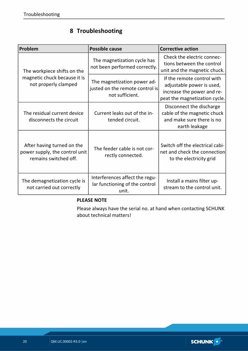
Problem Possible cause Corrective action
The workpiece shifts on the
magnetic chuck because it is
not properly clamped
The magnetization cycle has
not been performed correctly.
Check the electric connec-
tions between the control
unit and the magnetic chuck.
The magnetization power ad-
justed on the remote control is
not sufficient.
If the remote control with
adjustable power is used,
increase the power and re-
peat the magnetization cycle.
The residual current device
disconnects the circuit
Current leaks out of the in-
tended circuit.
Disconnect the discharge
cable of the magnetic chuck
and make sure there is no
earth leakage
After having turned on the
power supply, the control unit
remains switched off.
The feeder cable is not cor-
rectly connected.
Switch off the electrical cabi-
net and check the connection
to the electricity grid
The demagnetization cycle is
not carried out correctly
Interferences affect the regu-
lar functioning of the control
unit.
Install a mains filter up-
stream to the control unit.
PLEASE NOTE
Please always have the serial no. at hand when contacting SCHUNK
about technical matters!
8
Servicing and maintenance
QM.UC.00002-R3.0 |en 21
Servicing and maintenance
Excellent and careful maintenance is a decisive factor for optimum
safety, functioning and performance and a longer service life of
the product.
DANGER
Maintenance work must always be performed by an electrician.
The maintenance personnel must read this operating manual
carefully. Work inside the control unit must be done by SCHUNK
Service personnel only.
This type of control unit has exclusively been designed to be in-
stalled inside the electrical cabinet of the machine tool and
doesn’t therefore require any specific maintenance.
However, we recommend checking the conditions of the connec-
tion cables to the mains and to the magnetic chucks on a monthly
basis.
Furthermore, the proper operation of the residual current device
upstream of the control unit has to be checked regularly, accord-
ing to the manufacturer’s recommended intervals and methods.
Please follow the a.m. instructions and maintenance intervals so as
to avoid repairs and resulting down-times, failures and inconven-
ience.
Defective electrical and electromechanical components must al-
ways be replaced by SCHUNK Service personnel. If components are
replaced by the operator, this automatically renders the warranty
void.
After maintenance and before reconnecting and restarting the
control unit, all protection devices must be reinstalled.
9
Storage
22 QM.UC.00002-R3.0 |en
Storage
When storing the control unit for a longer period of time (max. 8
months), observe the following instructions to ensure its function-
ality up to the time of installation:
• Ensure correct packaging!
Recommendation: store the product in its original packaging.
• The control unit and the packaging should be inspected at regu-
lar intervals.
• Inspect packaging for outer damage and effects due to impacts
or weather.
• Make sure that the ambient temperature and humidity inside
the warehouse correspond to the specifications indicated in the
present user’s and maintenance manual.
10

Disposal
QM.UC.00002-R3.0 |en 23
Disposal
This product is made of plastic, electrical, and electronic compo-
nents. If it is taken out of operation, it has to be disposed of in
compliance with the applicable regulations.
As soon as the end of the lifecycle has been reached, the control
unit has to be decommissioned, i.e. put into a state in which it can
no longer be used for its original intended use and in which it is
still possible to recycle the raw materials contained.
NOTE
SCHUNK GmbH & Co. KG assumes no liability for material damage or personal injury that may result from reusing individual compo-nents of the control unit for purposes other than the original in-tended use! SCHUNK GmbH & Co. KG provides neither implicit nor explicit declarations about possible usability of recycled compo-nents after decommissioning the control unit.
Procedure for final decommissioning and disposal of the control
unit:
CAUTION
Risk of injury.
Decommissioning, disassembly and disposal of the control unit
must be performed by qualified persons using suitable tools.
1 Ensure that the machine tool has safely come to a halt. Dis-
connect all the electrical, hydraulic and pneumatic connec-
tions that could cause unexpected movements of the machine
or its components.
2 Disconnect the product from all devices.
� Have the control unit disposed of by a company specialized
in the disposal of electrical equipment.
11

Spare parts
24 QM.UC.00002-R3.0 |en
Spare parts
Please contact the SCHUNK service department for any spare parts
request.
12


