Autodesk® Civil 3D® Corridors: Cul-de-Sacs Are Not a Dead End Angel Espinoza – KETIV Technologies CV23-4 Learn how to create 3D cul-de-sac and knuckle designs with Autodesk Civil 3D. Learn step-by-step how to enhance your 3D models. This class will benefit all civil engineering professionals. Attendees should have general AutoCAD knowledge.. Key Topics: - Alignments and Profiles - Superimposed Profiles - Subassemblies and Assemblies - Corridors - Learn basic and intermediate designs Target Audience: All-levels of users of Autodesk Civil 3D. Engineers, designers, and technicians About the Speaker: Angel is the civil applications director at KETIV Technologies, in Fullerton California, where he has worked for over 8 years. Prior to KETIV, Angel had over 14 years of civil engineering experience with firms in Southern California. Angel's students consistently rate him as a very competent, fun, and articulate instructor. He first learned AutoCAD in 1987 from none other than Lynn Allen. His blog "Angel's Civil 3D Thoughts" is commonly referenced by many industry e- zines and directories. [email protected]
Transcript
Autodesk® Civil 3D® Corridors:
Cul-de-Sacs Are Not a Dead End Angel Espinoza – KETIV Technologies
CV23-4 Learn how to create 3D cul-de-sac and knuckle designs with Autodesk Civil 3D. Learn step-by-step how to enhance your 3D models. This class will benefit all civil engineering professionals. Attendees should have general AutoCAD knowledge..
Key Topics: - Alignments and Profiles - Superimposed Profiles - Subassemblies and Assemblies - Corridors - Learn basic and intermediate designs
Target Audience: All-levels of users of Autodesk Civil 3D. Engineers, designers, and technicians
About the Speaker: Angel is the civil applications director at KETIV Technologies, in Fullerton California, where he has worked for over 8 years. Prior to KETIV, Angel had over 14 years of civil engineering experience with firms in Southern California. Angel's students consistently rate him as a very competent, fun, and articulate instructor. He first learned AutoCAD in 1987 from none other than Lynn Allen. His blog "Angel's Civil 3D Thoughts" is commonly referenced by many industry e-zines and directories. [email protected]
Autodesk® Civil 3D® Corridors: Cul-de-Sacs Are Not a Dead End
2
Introduction
This 90-minute course will provide a complete fundamental understanding of corridor creation and implementation, with a focus on designing Cul-de-Sacs and Knuckles. With this knowledge you will be able to apply these and similar techniques to address the design challenges you face.
What are Corridors?
A corridor is a three-dimensional representation of a design feature that is built from various Autodesk Civil 3D objects and data. In order to build a corridor we need a surface, a horizontal alignment, a vertical alignment (profile), and various subassemblies that together define an assembly.
Corridor objects are created along one or more baselines (alignments) by placing 2D typical sections (assembly) at specified increments. Optionally, we can place matching slope subassemblies within our assembly that reach a surface model at each increment location as well (Figure 1).
Figure 1
Autodesk® Civil 3D® Corridors: Cul-de-Sacs Are Not a Dead End
3
Subassemblies
Subassemblies are the basic building blocks of corridor models.
A subassembly is an AutoCAD drawing object (AECC_Subassembly) that defines the geometry of a component used in a corridor section (assembly). Through the tool catalogs (Figure 2) and tool palette (Figure 3), Autodesk Civil 3D provides preconfigured subassemblies (Figure 4) for components such as travel lanes, curbs, side slopes and ditches. These parts are defined independently as subassemblies. You can link any type of subassembly to make up a typical assembly and apply the same assembly for a station range along an alignment. Subassemblies are defined by a set of points (markers), links, and optionally closed areas referred to as shapes.
The subassemblies provided with Autodesk Civil 3D have built-in intelligent behavior. They can automatically adapt to conditions such as superelevation and cut or fill requirements. For example, a side slope subassembly has variable slopes that change automatically depending on the depth of cut along the corridor. In fill conditions exceeding a given depth, the shoulder automatically widens to include a guardrail or barrier.
In addition to ready-to-use subassemblies, Civil 3D includes 12 generic subassemblies for user specified configurations. It also allows you to create custom subassembly objects with the “Create Subassembly from Polyline” command, or design more sophisticated ones using VBA macro code.
Some subassemblies can require corresponding surfaces, alignments and/or profiles for defining that geometry. These additional constraints are referred to as “Logical Names” in the Corridor creation process.
Figure 2 Figure 3 Figure 4
Autodesk® Civil 3D® Corridors: Cul-de-Sacs Are Not a Dead End
4
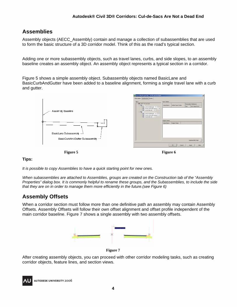
Assemblies Assembly objects (AECC_Assembly) contain and manage a collection of subassemblies that are used to form the basic structure of a 3D corridor model. Think of this as the road’s typical section.
Adding one or more subassembly objects, such as travel lanes, curbs, and side slopes, to an assembly baseline creates an assembly object. An assembly object represents a typical section in a corridor.
Figure 5 shows a simple assembly object. Subassembly objects named BasicLane and BasicCurbAndGutter have been added to a baseline alignment, forming a single travel lane with a curb and gutter.
Figure 5 Figure 6
Tips:
It is possible to copy Assemblies to have a quick starting point for new ones.
When subassemblies are attached to Assemblies, groups are created on the Construction tab of the “Assembly Properties” dialog box. It is commonly helpful to rename these groups, and the Subassemblies, to include the side that they are on in order to manage them more efficiently in the future.(see Figure 6)
Assembly Offsets When a corridor section must follow more than one definitive path an assembly may contain Assembly Offsets. Assembly Offsets will follow their own offset alignment and offset profile independent of the main corridor baseline. Figure 7 shows a single assembly with two assembly offsets.
Figure 7
After creating assembly objects, you can proceed with other corridor modeling tasks, such as creating corridor objects, feature lines, and section views.
Autodesk® Civil 3D® Corridors: Cul-de-Sacs Are Not a Dead End
5
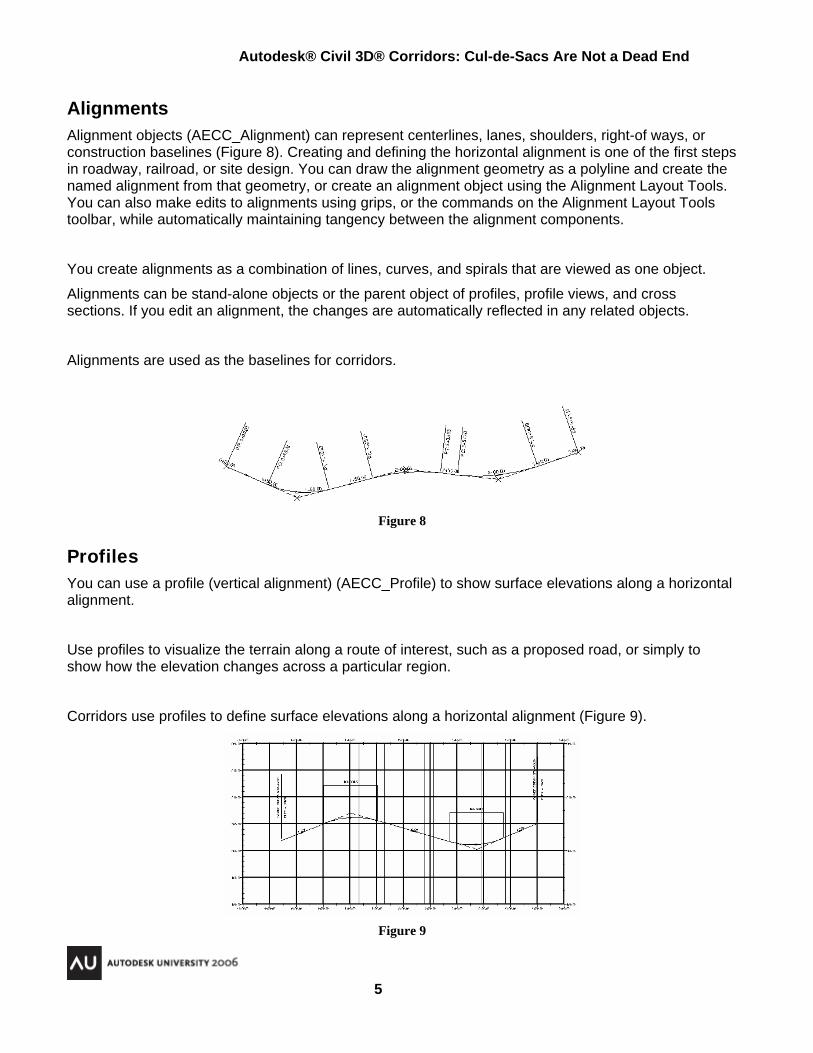
Alignments Alignment objects (AECC_Alignment) can represent centerlines, lanes, shoulders, right-of ways, or construction baselines (Figure 8). Creating and defining the horizontal alignment is one of the first steps in roadway, railroad, or site design. You can draw the alignment geometry as a polyline and create the named alignment from that geometry, or create an alignment object using the Alignment Layout Tools. You can also make edits to alignments using grips, or the commands on the Alignment Layout Tools toolbar, while automatically maintaining tangency between the alignment components.
You create alignments as a combination of lines, curves, and spirals that are viewed as one object.
Alignments can be stand-alone objects or the parent object of profiles, profile views, and cross sections. If you edit an alignment, the changes are automatically reflected in any related objects.
Alignments are used as the baselines for corridors.
Figure 8
Profiles You can use a profile (vertical alignment) (AECC_Profile) to show surface elevations along a horizontal alignment.
Use profiles to visualize the terrain along a route of interest, such as a proposed road, or simply to show how the elevation changes across a particular region.
Corridors use profiles to define surface elevations along a horizontal alignment (Figure 9).
Figure 9
Autodesk® Civil 3D® Corridors: Cul-de-Sacs Are Not a Dead End
6
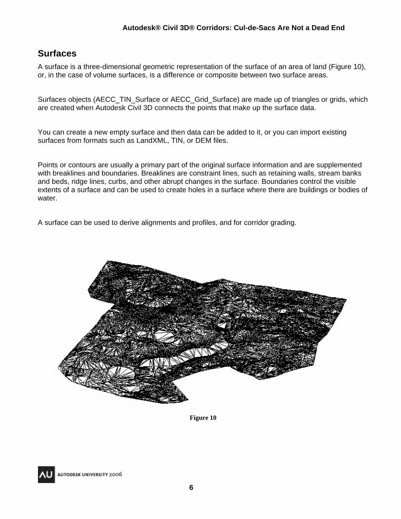
Surfaces A surface is a three-dimensional geometric representation of the surface of an area of land (Figure 10), or, in the case of volume surfaces, is a difference or composite between two surface areas.
Surfaces objects (AECC_TIN_Surface or AECC_Grid_Surface) are made up of triangles or grids, which are created when Autodesk Civil 3D connects the points that make up the surface data.
You can create a new empty surface and then data can be added to it, or you can import existing surfaces from formats such as LandXML, TIN, or DEM files.
Points or contours are usually a primary part of the original surface information and are supplemented with breaklines and boundaries. Breaklines are constraint lines, such as retaining walls, stream banks and beds, ridge lines, curbs, and other abrupt changes in the surface. Boundaries control the visible extents of a surface and can be used to create holes in a surface where there are buildings or bodies of water.
A surface can be used to derive alignments and profiles, and for corridor grading.
Figure 10
Autodesk® Civil 3D® Corridors: Cul-de-Sacs Are Not a Dead End
7
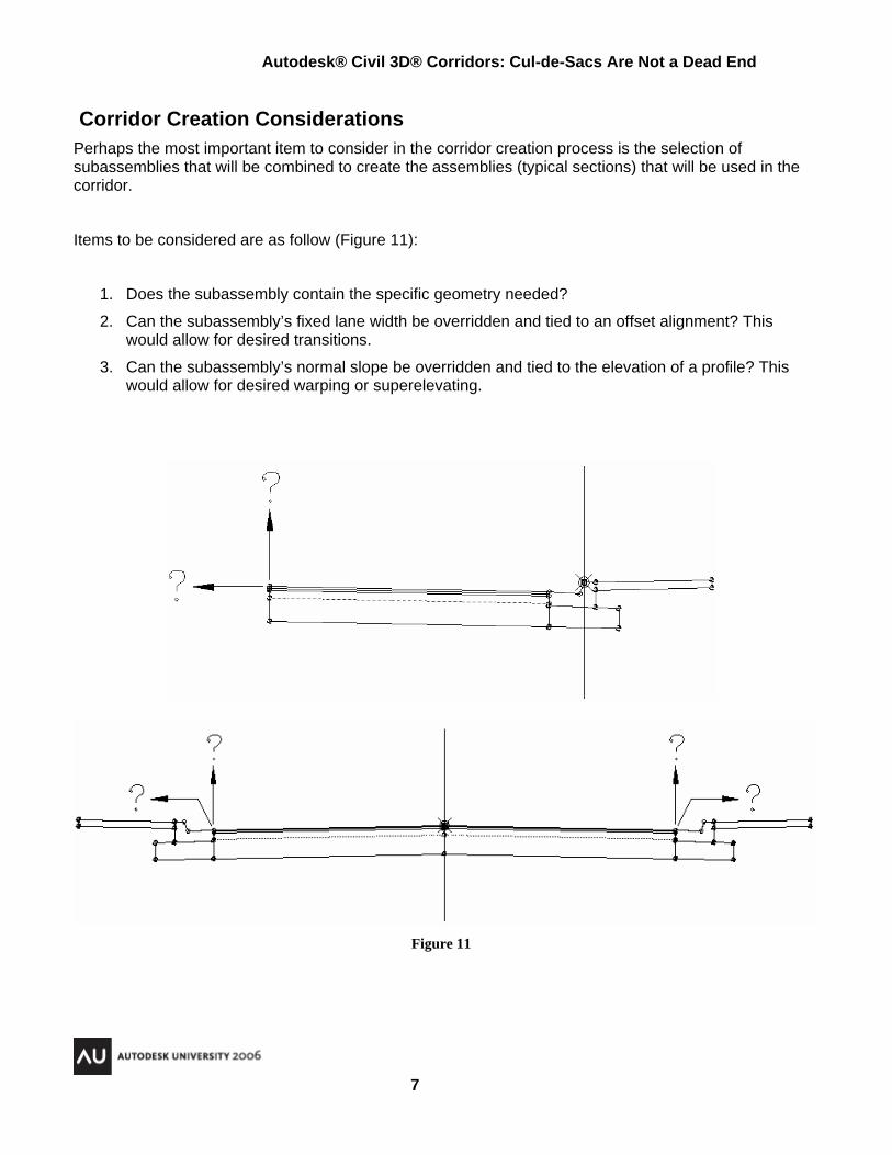
Corridor Creation Considerations Perhaps the most important item to consider in the corridor creation process is the selection of subassemblies that will be combined to create the assemblies (typical sections) that will be used in the corridor.
Items to be considered are as follow (Figure 11):
1. Does the subassembly contain the specific geometry needed?
2. Can the subassembly’s fixed lane width be overridden and tied to an offset alignment? This would allow for desired transitions.
3. Can the subassembly’s normal slope be overridden and tied to the elevation of a profile? This would allow for desired warping or superelevating.
Figure 11
Autodesk® Civil 3D® Corridors: Cul-de-Sacs Are Not a Dead End
8
Creating Corridor Objects General Overview Before you create corridors, you must have existing data, such as existing ground surfaces, alignments (centerline or baselines such as curb line or edge of pavement), profiles (vertical alignments), and typical sections (assemblies).
Set up procedure 1. Build the existing ground surfaces.
2. Design the horizontal alignments.
3. Sample existing ground profiles and draw in a profile view.
4. Design finished grade profiles (vertical alignments) in profile view.
5. Specify design speed and superelevation parameters for the curve groups on the centerline alignment and design offsets (if required).
6. Define the required subassemblies.
7. Create and maintain the required assemblies.
Corridor Creation 1. Use the Create Corridor or Create Simple Corridor commands.
2. Select the baseline (horizontal alignment) along which the corridor will run.
3. Select the corresponding profile (vertical alignment) along which the corridor will run.
4. Select the assemblies to use as typical sections on the corridor alignment.
In the Create Corridor Dialog Box address the following:
5. Assign addition parameters
a. Station range(s) to assign assemblies.
b. Frequency to assign assemblies on tangents, curves, and spirals.
c. Logical names for subassemblies that require them
i. Specify constraining alignments
ii. Specify constraining profiles
iii. Specify constraining surfaces
Optional as required:
6. Modify the corridor properties to create additional baselines with related profiles and assemblies.
7. Modify the corridor properties to create corridor surfaces and related boundaries.
Autodesk® Civil 3D® Corridors: Cul-de-Sacs Are Not a Dead End
9
Creating a Knuckle Corridor Object - Oustside Inward It is assumed that at this point that there are alignment objects and a proposed profile for alignments.
Create Assembly (For Knuckle and Cul-de-Sacs) 1. Click Corridors menu > Create Assembly.
2. In the Create Assembly Dialog Box (Figure 12), in the Name field, enter a name for the assembly. (In this example we create 18’ Rt In and 18’ Lt In)
3. For Description, enter an optional description of the assembly.
4. For Assembly Style and Code Set Style, you can accept the default style, select another style, or create a new style. Figure 12
5. Click to select a layer. Note: If you do not select a layer, the corridor is placed on the default layer.
6. Click OK.
7. To insert the assembly into the drawing, click a baseline location in the drawing. Notice the baseline point (Figure 13). This location is attached to the alignment and profile. Figure 13
Attach Subassemblies 1. Select UrbanCurbGutterGeneral subassembly from a tool palette in the Tool
Palettes window (Figure 14), or from a tool catalog through the Content Browser.
2. To attach the subassembly to the assembly baseline location, select the baseline point or the baseline marker (Figure 15). Typically, the baseline marker displays as a vertical line.
The subassembly name is displayed in the Subassemblies collection in the Prospector tree.
A subassembly group is added to the assembly. Figure 14
3. With AutoCAD’s move command Move the UrbanCurbGutterGeneral subassembly so that the top of curb is at the baseline point. (Figure 16)
4. To add a subassemblies to the subassembly just added, select the new subassembly (LaneTowardCrown) in a tool palette, or in a tool catalog, then select an appropriate marker point on the previously added subassembly (Figure 17). Use the Properties Palette to set appropriate settings such as side and width.
Note 1: It will be necessary to construct another assembly that is a mirror image (Figure 18). Name it 18’ Lt In
Autodesk® Civil 3D® Corridors: Cul-de-Sacs Are Not a Dead End
10
Create Corridor 1. Click Corridors menu > Create Corridor.
2. Select an alignment in the drawing or press Enter to select an alignment in the “Select An Alignment” dialog box. (Figure 19)
Figure 19
3. Select a profile in the drawing or press Enter to select a profile in the “Select a Profile” dialog box. This profile should correspond with the appropriate top of curb.
4. Select an assembly in the drawing or press Enter to select an assembly in the “Select an Assembly” dialog box. (Select assembly 18’ Lt In for alignment shown above)
5. In the Create Corridor Dialog Box, in the “Corridor name:” field, enter a name for the corridor. (Figure 20)
Figure 20
To name the corridor, select its default name and enter a new name, or use the name template.
Autodesk® Civil 3D® Corridors: Cul-de-Sacs Are Not a Dead End
11
6. In the Description field, enter a description for the corridor. (Figure 21)
7. Click to select a layer. Note: If you do not select a layer, the corridor is placed on the default layer.
Figure 21
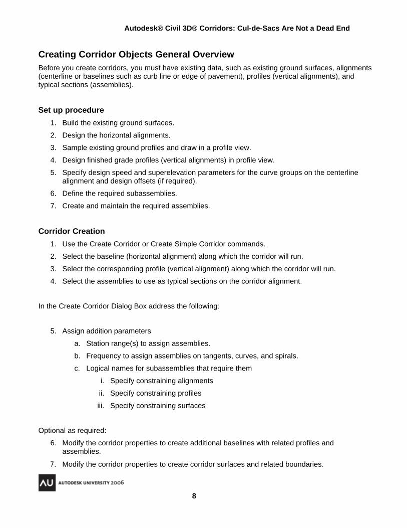
8. Press the “Add a new baseline” button (blue plus sign) (Figure 21) to add the second baseline alignment (Figure 22).
Figure 22
Autodesk® Civil 3D® Corridors: Cul-de-Sacs Are Not a Dead End
12
Figure 23
9. Right Click on second baseline and choose “Add Region…” . This will then allow the selection of second profile and second assembly (this assembly should be 18’ Rt In). You will end up with Figure 24.
Figure 24
Autodesk® Civil 3D® Corridors: Cul-de-Sacs Are Not a Dead End
13
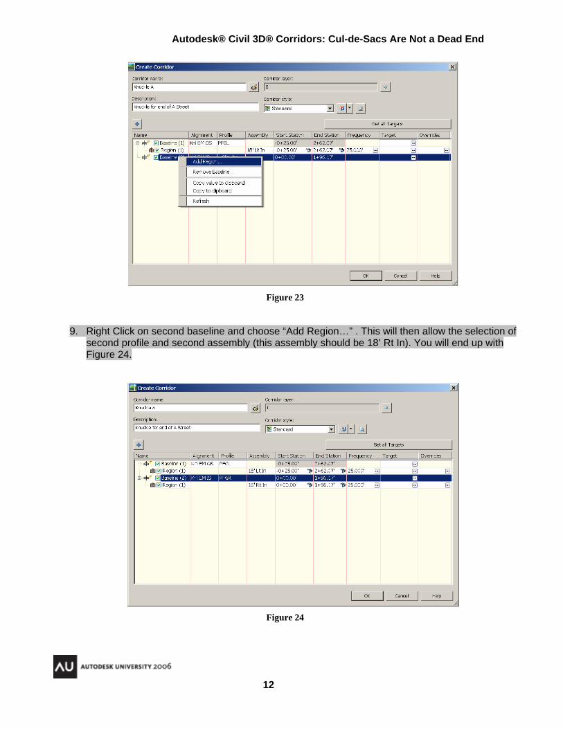
10. Press the “Set all targets” button to assign an alignment and profile to control crown line in the “Target Mapping” dialog box. Figure 25.
Figure 25
11. Press Ok to return to “Create Corridor” dialog box.
12. Press the buttons within the “Frequency” column (Figure 26) to bring up the “Frequency to Apply Assemblies” dialog box (Figure 27).
13. Modify Frequency (values of 4 to 10 tend to work well for Knuckles and Cul-de-Sacs).
14. Repeat per baseline. Figure 26
Figure 27
Autodesk® Civil 3D® Corridors: Cul-de-Sacs Are Not a Dead End
14
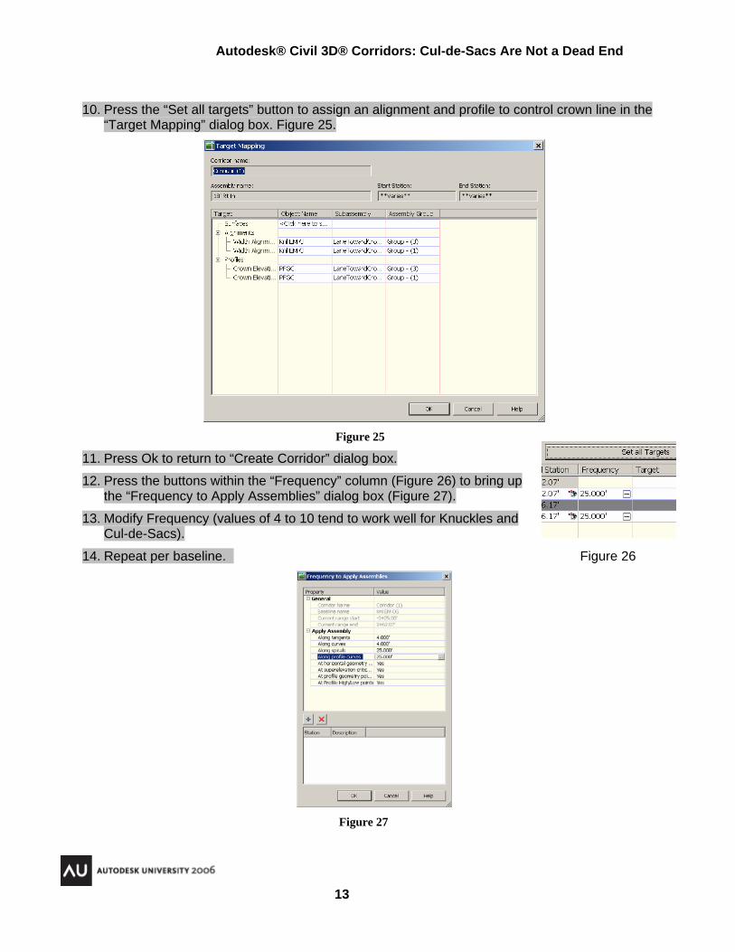
15. Press the buttons within the Start Station column and End Station column (Figure 28) to specify where corridor will begin and end.
Figure 28
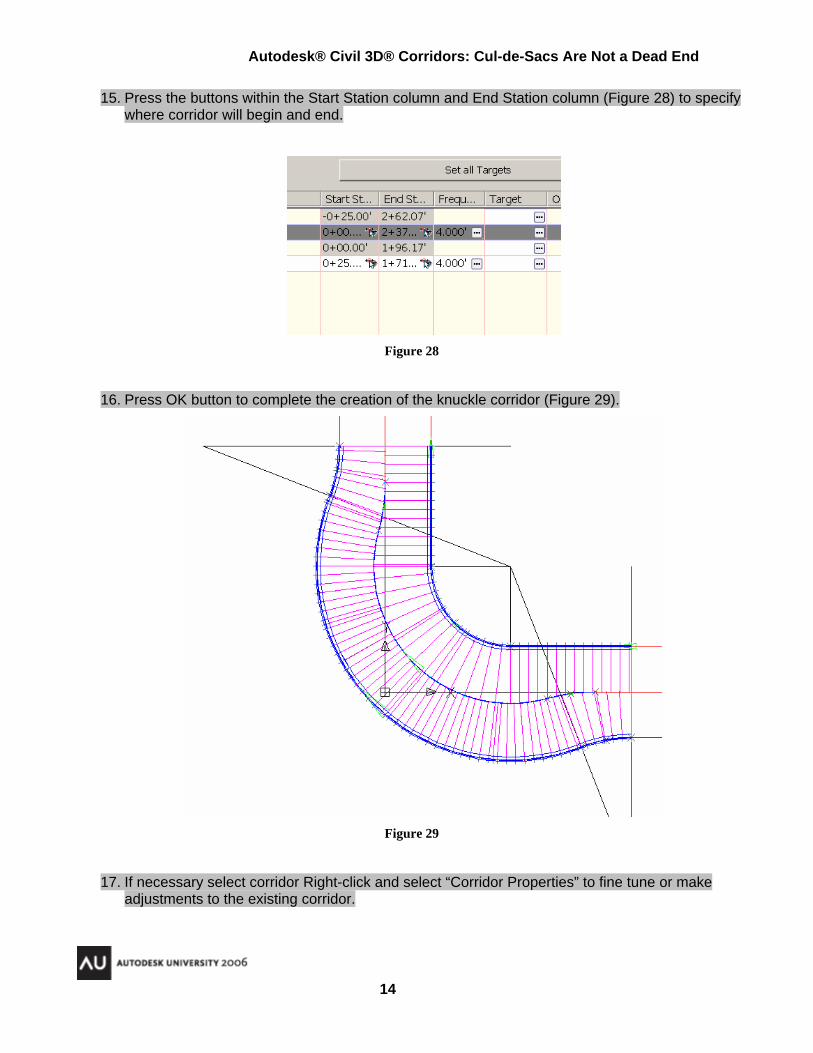
16. Press OK button to complete the creation of the knuckle corridor (Figure 29).
Figure 29
17. If necessary select corridor Right-click and select “Corridor Properties” to fine tune or make adjustments to the existing corridor.
Autodesk® Civil 3D® Corridors: Cul-de-Sacs Are Not a Dead End
15
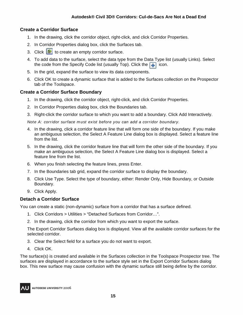
Create a Corridor Surface 1. In the drawing, click the corridor object, right-click, and click Corridor Properties.
2. In Corridor Properties dialog box, click the Surfaces tab.
3. Click to create an empty corridor surface.
4. To add data to the surface, select the data type from the Data Type list (usually Links). Select the code from the Specify Code list (usually Top). Click the icon.
5. In the grid, expand the surface to view its data components.
6. Click OK to create a dynamic surface that is added to the Surfaces collection on the Prospector tab of the Toolspace.
Create a Corridor Surface Boundary 1. In the drawing, click the corridor object, right-click, and click Corridor Properties.
2. In Corridor Properties dialog box, click the Boundaries tab.
3. Right-click the corridor surface to which you want to add a boundary. Click Add Interactively.
Note A: corridor surface must exist before you can add a corridor boundary.
4. In the drawing, click a corridor feature line that will form one side of the boundary. If you make an ambiguous selection, the Select A Feature Line dialog box is displayed. Select a feature line from the list.
5. In the drawing, click the corridor feature line that will form the other side of the boundary. If you make an ambiguous selection, the Select A Feature Line dialog box is displayed. Select a feature line from the list.
6. When you finish selecting the feature lines, press Enter.
7. In the Boundaries tab grid, expand the corridor surface to display the boundary.
8. Click Use Type. Select the type of boundary, either: Render Only, Hide Boundary, or Outside Boundary.
9. Click Apply.
Detach a Corridor Surface You can create a static (non-dynamic) surface from a corridor that has a surface defined.
1. Click Corridors > Utilities > “Detached Surfaces from Corridor…”.
2. In the drawing, click the corridor from which you want to export the surface.
The Export Corridor Surfaces dialog box is displayed. View all the available corridor surfaces for the selected corridor.
3. Clear the Select field for a surface you do not want to export.
4. Click OK.
The surface(s) is created and available in the Surfaces collection in the Toolspace Prospector tree. The surfaces are displayed in accordance to the surface style set in the Export Corridor Surfaces dialog box. This new surface may cause confusion with the dynamic surface still being define by the corridor.
Autodesk® Civil 3D® Corridors: Cul-de-Sacs Are Not a Dead End
16
Intersections Samples
Figure 27
Figure 28
Autodesk® Civil 3D® Corridors: Cul-de-Sacs Are Not a Dead End
17
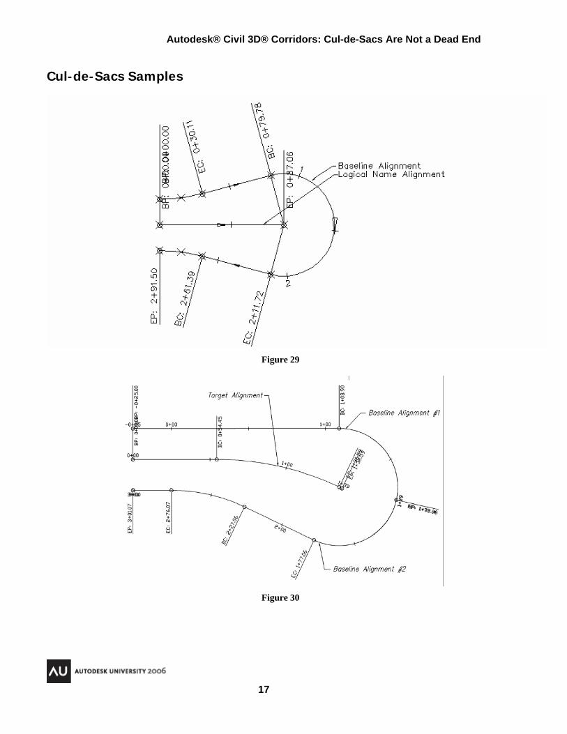
Cul-de-Sacs Samples
Figure 29
Figure 30
Autodesk® Civil 3D® Corridors: Cul-de-Sacs Are Not a Dead End
18
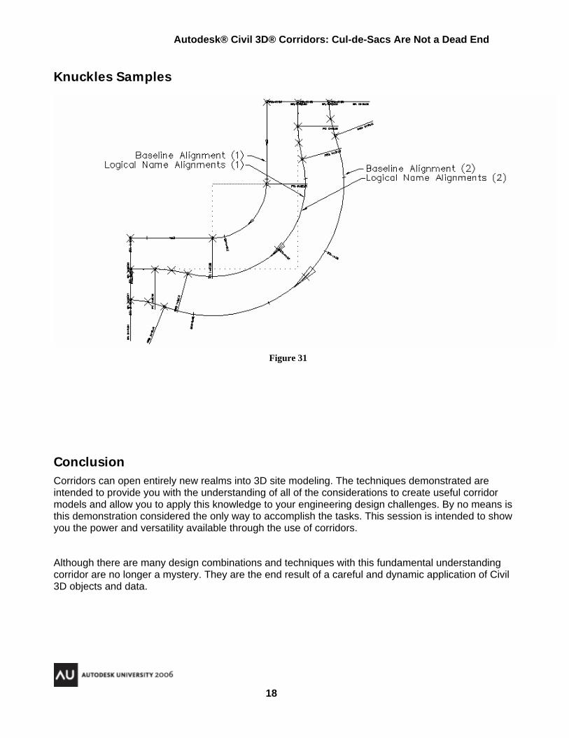
Knuckles Samples
Figure 31
Conclusion Corridors can open entirely new realms into 3D site modeling. The techniques demonstrated are intended to provide you with the understanding of all of the considerations to create useful corridor models and allow you to apply this knowledge to your engineering design challenges. By no means is this demonstration considered the only way to accomplish the tasks. This session is intended to show you the power and versatility available through the use of corridors.
Although there are many design combinations and techniques with this fundamental understanding corridor are no longer a mystery. They are the end result of a careful and dynamic application of Civil 3D objects and data.