31
Mesoscopic Devices Demonstration of a 75 W portable SOFC generator Jerry Martin—Mesoscopic Devices, LLC Tad Armstrong—MSRI Anil Virkar—Univ. of Utah Mesoscopic Devices

Mesoscopic Devices
Demonstration of a 75 W portable SOFC generator
Jerry Martin—Mesoscopic Devices, LLCTad Armstrong—MSRI
Anil Virkar—Univ. of Utah
Mesoscopic Devices

Mesoscopic Devices

Mesoscopic Devices
OutlineWhy portable SOFC?System designStack requirementsPerformanceNext generation 250 W generator

Mesoscopic Devices
Why portable SOFC’s?Operation on hydrocarbon fuels
High energy density fuel>3X advantage over methanol or hydridesSafe, readily available fuels
Simple fuel reformingCPOX is small, fast, lightweight
Quieter than IC-engine generatorsLighter than batteries

Mesoscopic Devices
SOFC advantagesQuiet
<52 dBAUndetectable at 10 m outside
Good fuel efficiencyEstimated 3160 W-hr/kg fuel (~26%)
CompactLunchbox size, ~3 kg
High peak-to-average power ratiosVia battery hybridization.

Mesoscopic Devices
SOFC advantages (cont’d.)Common fuels
Propane, kerosene todayGasoline and diesel with development
Operation in wide range of ambient conditionsHigh specific energy compared to batteries
Up to 2000 W-hr/kgBetter than batteries for periods longer than 12 hours
Long periods between maintenance500 hours is a reasonable near-term goalUp to 2000 hours with development

Mesoscopic Devices
SOFC challengesSlow startup and shutdown(current generation)
~1 hour to power delivery~1 hour for safe shutdown Not suitable for frequent start-stop cycles
Limited sulfur tolerance Sulfur must be reduced to ppm levels in fuel
Some degradation with thermal cycling
Mesoscopic Devices
Mesoscopic Devices
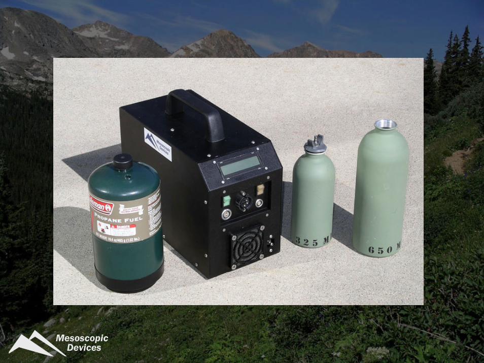
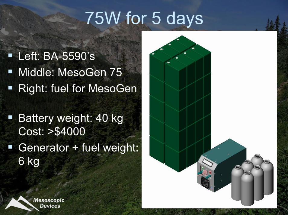
75W for 5 days
Left: BA-5590’sMiddle: MesoGen 75Right: fuel for MesoGen
Battery weight: 40 kgCost: >$4000Generator + fuel weight: 6 kg

Mesoscopic Devices
System configurationFuel options
PropaneDesulfurized keroseneFuel supply subsystem is only change
Optimized for multi-day missions:Direct power for communications equipmentBattery charging
12 or 24 V DC options

Mesoscopic Devices
Block diagram
Air blower Stack
+-
Fuel tank(liquid)
fuelpump
Insulation
recuperator
vaporizerpower
conditioning
partialoxidation
tail-gascombustor

Mesoscopic Devices
CPOX implicationsSimplest reformerNo water to recover or carryMillisecond contact time design leads to very small reformersFast start, fast response
Leads to dilute anode stream 25% H2, 21% CO47% N2, 6% H2O+CO2
Mesoscopic Devices
System integrationBOP components demonstrated to> 1000 hrs between maintenanceControl system
Steady state controlFully automated startup and shutdown
Battery hybridization provides peak power capability

Mesoscopic Devices
Integrated 75 W system

Mesoscopic Devices
System integration challengesAccurate fuel and air metering at minimum weight, size and power drawAir blower power draw, lifetimeStack performance at high fuel utilization

Mesoscopic Devices
Mass breakout: 75W system
Fuel 1.8-6 kg
Stack 0.7 kg
BOP 2.3 kg
3 day mission, 75W 10 day mission, 75W
Weight Distribution (Wet)
fuel71%
stack8%
BOP21%
Weight Distribution (Wet)
fuel42%
stack16%
BOP42%

Mesoscopic Devices
Stack requirementsHigh volumetric power densityHigh fuel utilizationHigh cell voltage
Must simultaneously achieve all three for lightweight, efficient system
Critical parameters:Stack power density >400 W/LStack specific power > 100 W/kgLow dP, <0.5 psi (3 kPa)

Mesoscopic Devices
Stack performance requirements
High performance on dilute reformate stream (~50% (H2 + CO), 50% N2)Multiple thermal cyclesLight weight (including compression hardware, headers, etc.)

Mesoscopic Devices
Planar stacks17 cells16 cm2 active area0.7 kg / 0.2 liters64 x 64 x 47 mm~450 W/liter at operating conditions12 V / 7.5 A / 90 W
1.8 in.
47 mm
2.5 in.
64 mm

Mesoscopic Devices
Stack power curve50% H2 in N260% fuel util.40% air util.
0
5
10
15
20
0
25
50
75
100
0 2 4 6 8 10
Volta
ge, V
Power, W
Current, A
Mesoscopic Devices
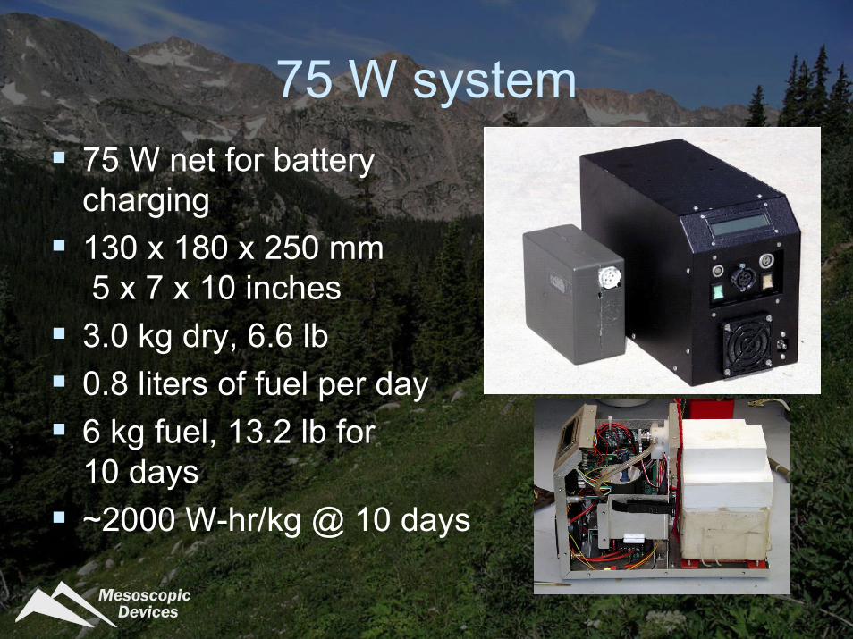
75 W system75 W net for battery charging130 x 180 x 250 mm5 x 7 x 10 inches
3.0 kg dry, 6.6 lb0.8 liters of fuel per day6 kg fuel, 13.2 lb for 10 days~2000 W-hr/kg @ 10 days

Mesoscopic Devices
TemperaturesStack temperature ~ 800 CCase temperature ~ 60 CExhaust gas ~ 120 C
250 W dissipation

Mesoscopic Devices
System load curve
0
5
10
15
20
0
10
20
30
40
50
60
70
80
0 1 2 3 4 5 6 7
volta
ge (V
) power (W
)
current (A)
propane5-17-2005
Mesoscopic Devices
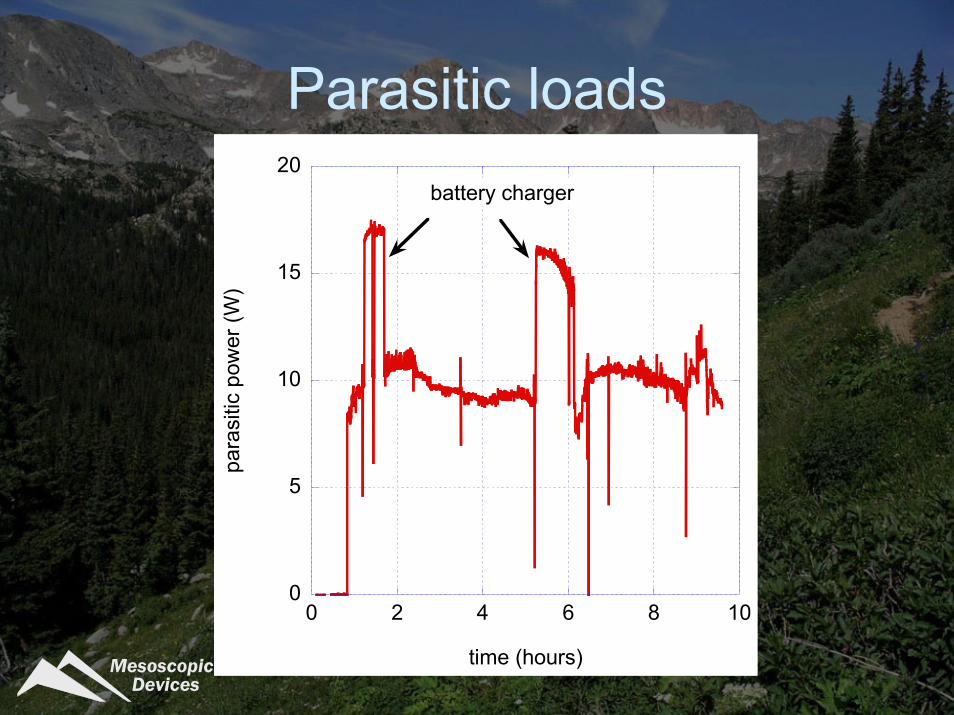
Parasitic loads
0
5
10
15
20
0 2 4 6 8 10
para
sitic
pow
er (W
)
time (hours)
battery charger

Mesoscopic Devices
Effect of hybridization
0
5
10
15
0
10
20
30
40
50
60
0 1 2 3 4 5
volta
ge (V
) power (W
)
currrent (A)hy
brid
ope
ratio
n
Mesoscopic Devices
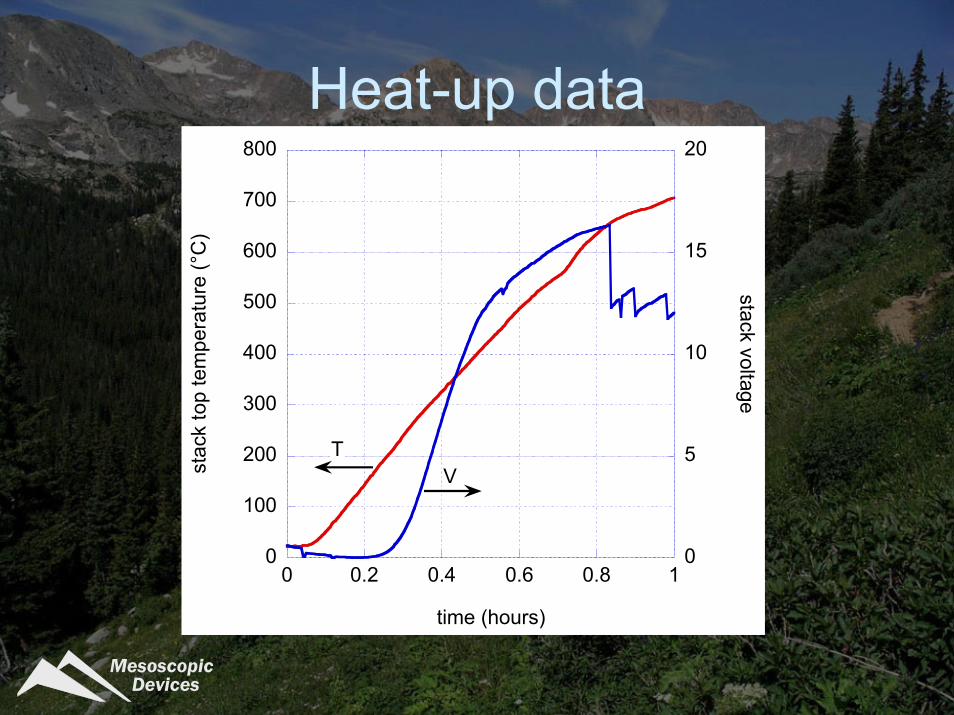
Heat-up data
0
100
200
300
400
500
600
700
800
0
5
10
15
20
0 0.2 0.4 0.6 0.8 1
stac
k to
p te
mpe
ratu
re (°
C)
stack voltage
time (hours)
TV

Mesoscopic Devices
Gross and net power
0
10
20
30
40
50
60
0 2 4 6 8 10 12 14
load
pow
er (W
)
time (hours)
acquire load curves
stack starts to carry internal loads (42 min)
stack power
load power

Mesoscopic Devices
Addressing challengesChanges for future systems
Tubular stacksTighter integration
Leads toShorter startup timesHigher power density
Air supply system changesLengthen maintenance interval

Mesoscopic Devices
Hot zone integrationTight integration in the hot zone is critical75 W system
Planar stacksVolume: 700 ml
250 W systemTubular stacksVolume : 1265 ml85% increase inhot zone volumetricpower density

Mesoscopic Devices
Tube test resultsSimulated CPOX60% fuel util.Ø10 mm
0
0.2
0.4
0.6
0.8
1
1.2
0
0.05
0.1
0.15
0.2
0.25
0.3
0 2 4 6 8 10 12 14
Vol
ts (V
)
Pow
er (W/cm
2)
Current (A)

Mesoscopic Devices
AcknowledgementsThis work was supported by
US Defense Advanced Research Projects Agency (contract MDA972-03-C-0060) Office of Naval Research (contract N00014-05-C-0051)


