Design Practice Prof. Shantanu Bhattacharya Department of Mechanical Engineering Indian Institute of Technology, Kanpur Lecture - 36 and 37 Introduction to Group Technology Welcome to the course Design Practice lecture module 36 and 37. I am Sanjay Kumar, course TA for this course and today we will study a new topic that is called Group Technology. (Refer Slide Time: 00:32) Group technology, in this topic you will know how to organise the workshop such that where machines will be assembled and parts will be distinguished with each other. Group technology is a manufacturing philosophy that seeks to improve productivity. Actually the motto of this group technology is to improve the productivity by grouping parts and products with similar characteristics into families and forming production cell with a group of dissimilar machining process. It means it is a grouping of products and machine, so that your productivity can be improved. This was first introduced by Frederick Taylor in 1999 as a way to improve productivity and one of the long term benefit of group technology is it helps implement a manufacturing strategy aimed at greater automation, using use your GT. You can you can transform your industry into an automation that is the requirement of 21 st century automation. 1
Transcript
Design PracticeProf. Shantanu Bhattacharya
Department of Mechanical EngineeringIndian Institute of Technology, Kanpur
Lecture - 36 and 37Introduction to Group Technology
Welcome to the course Design Practice lecture module 36 and 37. I am Sanjay Kumar, course
TA for this course and today we will study a new topic that is called Group Technology.
(Refer Slide Time: 00:32)
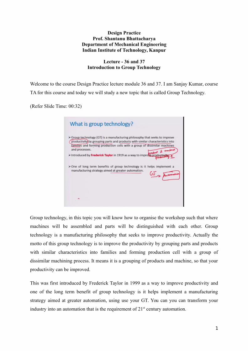
Group technology, in this topic you will know how to organise the workshop such that where
machines will be assembled and parts will be distinguished with each other. Group
technology is a manufacturing philosophy that seeks to improve productivity. Actually the
motto of this group technology is to improve the productivity by grouping parts and products
with similar characteristics into families and forming production cell with a group of
dissimilar machining process. It means it is a grouping of products and machine, so that your
productivity can be improved.
This was first introduced by Frederick Taylor in 1999 as a way to improve productivity and
one of the long term benefit of group technology is it helps implement a manufacturing
strategy aimed at greater automation, using use your GT. You can you can transform your
industry into an automation that is the requirement of 21st century automation.
1
(Refer Slide Time: 01:46)
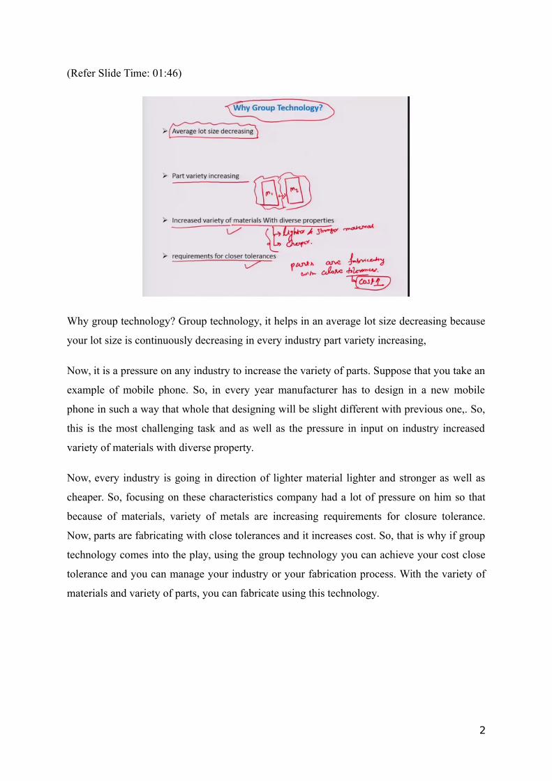
Why group technology? Group technology, it helps in an average lot size decreasing because
your lot size is continuously decreasing in every industry part variety increasing,
Now, it is a pressure on any industry to increase the variety of parts. Suppose that you take an
example of mobile phone. So, in every year manufacturer has to design in a new mobile
phone in such a way that whole that designing will be slight different with previous one,. So,
this is the most challenging task and as well as the pressure in input on industry increased
variety of materials with diverse property.
Now, every industry is going in direction of lighter material lighter and stronger as well as
cheaper. So, focusing on these characteristics company had a lot of pressure on him so that
because of materials, variety of metals are increasing requirements for closure tolerance.
Now, parts are fabricating with close tolerances and it increases cost. So, that is why if group
technology comes into the play, using the group technology you can achieve your cost close
tolerance and you can manage your industry or your fabrication process. With the variety of
materials and variety of parts, you can fabricate using this technology.
2
(Refer Slide Time: 03:53)
So, I am taking one example for that. So, this is the fast food chain, doctor, dentists, and also
manufacturing to find fast food chain. What happens one company is opening lot of store all
over the world, but most challenge of task is mental test, taste of food and as well as quality
of food. So, with the help of food technology, you can achieve these kind of properties for
food chain store and similarly, you can see here the family of part. I will explain what the
family of part is. You know you can say see here they are four parts and each has some
similarity. All are circular in shape.
So, this is the circular shape and you can distinguish these objects by circular shaped. So,
these are called family of part.
3
(Refer Slide Time: 05:15)
So, implementing group technology, where to implement good technology? Generally, plants
using traditional batch production and process type layout where you can implement your
group technology if the parts can be grouped into part family, your part family.
So, product with similar characteristics can be group together, and this group is known as part
family where you are grouping variety of products with the similar characteristics. How to
implement group technology? First you will have to identify part family, so that you can
make lot of family; family 1, family 2, family 3 and each family has a variety of parts which
have a similar characteristic, rearrange production machine into machine cell. So, to
implement group technology will have to rearrange your production machine, existing
production machine into machine sale, machine cell.
So, machine cell, what is machine cell? It is a group of machines with similar kind of
operation. For example, drilling machine, boring machine. You can plug both machine into
one, so that because main task of these machines are to make a hole and to enlarge a hole
with the higher dimension. So, the grouping of these machines with similar characteristics is
called machine cells. So, in a group technology you will have to do first two things. First you
will have to group together, you will have to make a part family, first one and second one
machine cells. Then part family variety of parts is a group of variety of parts and here as well
as variety of machines. So, you will have to first identify your part family, then you will have
4
to make a machine cell and for machine cell, you will have to change rearrange your
production machine.
(Refer Slide Time: 07:59)
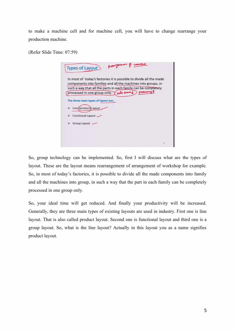
So, group technology can be implemented. So, first I will discuss what are the types of
layout. These are the layout means rearrangement of arrangement of workshop for example.
So, in most of today’s factories, it is possible to divide all the made components into family
and all the machines into group, in such a way that the part in each family can be completely
processed in one group only.
So, your ideal time will get reduced. And finally your productivity will be increased.
Generally, they are three main types of existing layouts are used in industry. First one is line
layout. That is also called product layout. Second one is functional layout and third one is a
group layout. So, what is the line layout? Actually in this layout you as a name signifies
product layout.
5
(Refer Slide Time: 09:19)
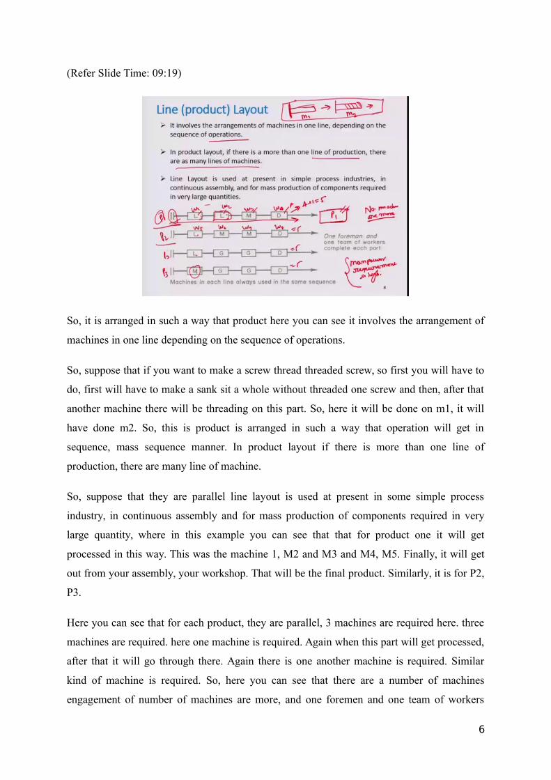
So, it is arranged in such a way that product here you can see it involves the arrangement of
machines in one line depending on the sequence of operations.
So, suppose that if you want to make a screw thread threaded screw, so first you will have to
do, first will have to make a sank sit a whole without threaded one screw and then, after that
another machine there will be threading on this part. So, here it will be done on m1, it will
have done m2. So, this is product is arranged in such a way that operation will get in
sequence, mass sequence manner. In product layout if there is more than one line of
production, there are many line of machine.
So, suppose that they are parallel line layout is used at present in some simple process
industry, in continuous assembly and for mass production of components required in very
large quantity, where in this example you can see that that for product one it will get
processed in this way. This was the machine 1, M2 and M3 and M4, M5. Finally, it will get
out from your assembly, your workshop. That will be the final product. Similarly, it is for P2,
P3.
Here you can see that for each product, they are parallel, 3 machines are required here. three
machines are required. here one machine is required. Again when this part will get processed,
after that it will go through there. Again there is one another machine is required. Similar
kind of machine is required. So, here you can see that there are a number of machines
engagement of number of machines are more, and one foremen and one team of workers
6
complete each part. Here in each of production line they are one foremen and one team of
workers. Worker 1 here W2, W3, W4. There are four workers in a one production line, other
in production line 2, another they will be W5, W6, W7 ,W8 here. So, you can see that here
manpower requirement is high. So, in this kind of layout machines requirements are high and
as well as manpower requirement is high. So, cost will be, the product cost will be very high
as compared to other layout process.
(Refer Slide Time: 11:59)
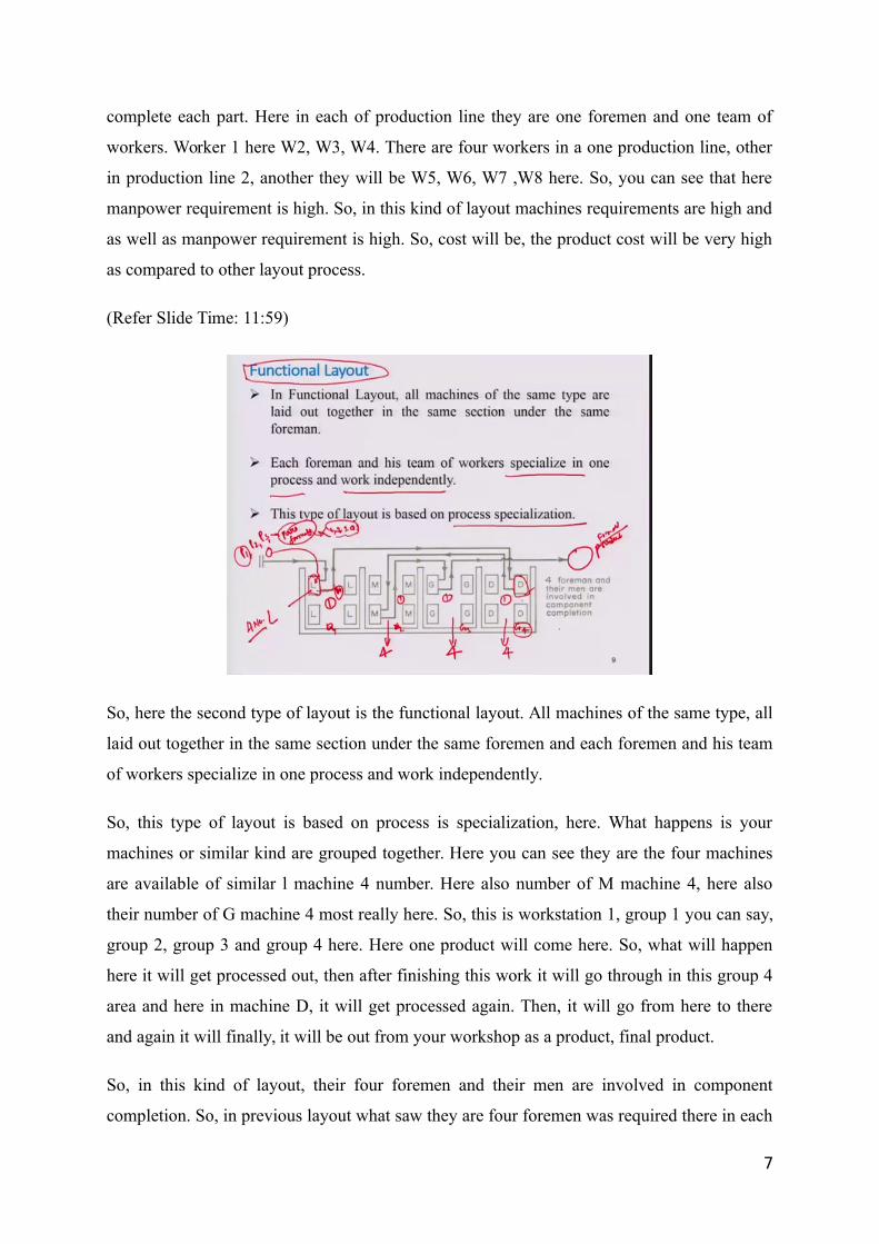
So, here the second type of layout is the functional layout. All machines of the same type, all
laid out together in the same section under the same foremen and each foremen and his team
of workers specialize in one process and work independently.
So, this type of layout is based on process is specialization, here. What happens is your
machines or similar kind are grouped together. Here you can see they are the four machines
are available of similar l machine 4 number. Here also number of M machine 4, here also
their number of G machine 4 most really here. So, this is workstation 1, group 1 you can say,
group 2, group 3 and group 4 here. Here one product will come here. So, what will happen
here it will get processed out, then after finishing this work it will go through in this group 4
area and here in machine D, it will get processed again. Then, it will go from here to there
and again it will finally, it will be out from your workshop as a product, final product.
So, in this kind of layout, their four foremen and their men are involved in component
completion. So, in previous layout what saw they are four foremen was required there in each
7
production line, there are four workers with one foreman. So, number of workers were 5,
human being was four plus one equals to 5. Again here 5 and in this case you can see that
they are only 1 foreman, and 1 foreman, 1 foreman, 1 foreman, here foreman and each
machine. If these machines are worked in sequentially, then only one worker will be required.
If all machines are engaged parallel that is may be possible that more than one worker will be
required in each group.
So, as compared to your product layout, here number of human being, woman worker will be
reduced and also, there will be it will act in a functional manner. So, suppose that you have
four three-part family P1, P2, P3, these are the part family. Part family I told you earlier; what
is the group of similar kind of parts. Here it may be possible that 1, 2, 3, 4. Therefore, parts in
will be there in one group. So, that is called P3 part family. So, suppose that one-part family
will come here and there one drilling is required. So, it will all drilling will be processed in
this machine, then it will transfer to this machine again. So, it works in a functional manner.
(Refer Slide Time: 14:57)
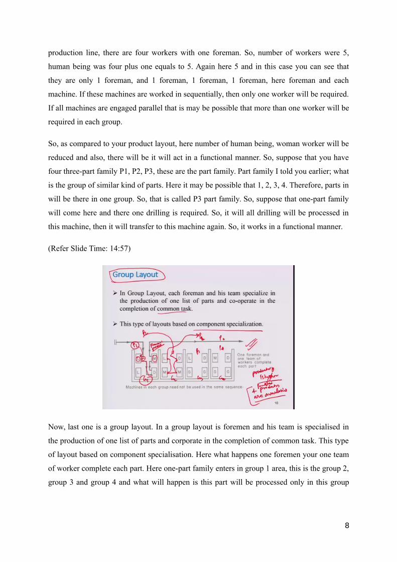
Now, last one is a group layout. In a group layout is foremen and his team is specialised in
the production of one list of parts and corporate in the completion of common task. This type
of layout based on component specialisation. Here what happens one foremen your one team
of worker complete each part. Here one-part family enters in group 1 area, this is the group 2,
group 3 and group 4 and what will happen is this part will be processed only in this group
8
only, and one and each machine there will be one specialized person assigned to these
machines.
So, what will happen when it will come to here, then specialized person will process this part
in this machine. Again this will transfer it to this machine drilling and after that drilling,
milling will take place here. So, as it machines one worker is assigned and these are
specialised doing this work in lathe. So, here what happens these are after the exit. It will
come out as a finished product.
So, here again part P2 will come enter in this place like this one, then it will, they may be
done this again this one. Then, it will enter it to two lathe and after that it will take out. So,
here you can see that all family part 1, P1, P2, P3, P4 a process parallel with a similar number
of human beings as compared to functional layout, but here productivity is higher in this case
because your all machines are engaged in the same time and your four products are available,
finished product are available. So, this is the most appropriate layout that is being used in
industry that is called group layout.
(Refer Slide Time: 17:13)
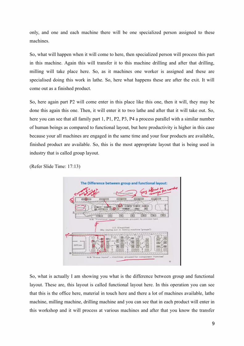
So, what is actually I am showing you what is the difference between group and functional
layout. These are, this layout is called functional layout here. In this operation you can see
that this is the office here, material in touch here and there a lot of machines available, lathe
machine, milling machine, drilling machine and you can see that in each product will enter in
this workshop and it will process at various machines and after that you know the transfer
9
transportation of this product part from one machine to another machine, it creates a zigzag
path.
So, it is very complicated and it is very difficult to manage for a production engineer to
manage the workshop. So, if number of part are less, then it may work out, but generally in
actual condition what happens due to variety of parts are processed in one workshop this day.
So, these are the parts, these are the very becomes very complicated. So, as compared to your
functional layout here, you can see that in a group layout here you can see that everything is
well mannered designed. One part will enter through in one group and here what will happen,
it will go through there. Then, lathe machine, then milling drilling and after that it will come
out as a reached product.
So, here you can see that it a very simplified. It takes very low space and lower in one’s part
move to in a very lower area as compared to your functional parts. Suppose that here one part
enters here, it will go through there, then it will come out there. So, it moves. So,
transportation time is higher. Transportation time of part in a workshop is higher, here. It is
very parts are fabricated in a very simplified manner. So, I am giving you one example.
(Refer Slide Time: 19:46)
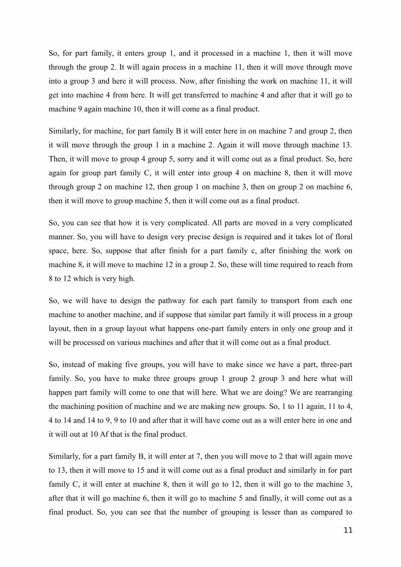
Suppose that we have a three-part family A, B and C. So, in a functional layout what happens
they are group of machines of similar functionality is placed at group wise 1, 2 here 11, 12,
13 here 4, 5, 6, 7, 8, 9, 10, 11, 12, 13, 14, 15. There fifteen machines are available and it has
we have divided in five groups; group 1 group 2, group 3, group 4 and group 5.
10
So, for part family, it enters group 1, and it processed in a machine 1, then it will move
through the group 2. It will again process in a machine 11, then it will move through move
into a group 3 and here it will process. Now, after finishing the work on machine 11, it will
get into machine 4 from here. It will get transferred to machine 4 and after that it will go to
machine 9 again machine 10, then it will come as a final product.
Similarly, for machine, for part family B it will enter here in on machine 7 and group 2, then
it will move through the group 1 in a machine 2. Again it will move through machine 13.
Then, it will move to group 4 group 5, sorry and it will come out as a final product. So, here
again for group part family C, it will enter into group 4 on machine 8, then it will move
through group 2 on machine 12, then group 1 on machine 3, then on group 2 on machine 6,
then it will move to group machine 5, then it will come out as a final product.
So, you can see that how it is very complicated. All parts are moved in a very complicated
manner. So, you will have to design very precise design is required and it takes lot of floral
space, here. So, suppose that after finish for a part family c, after finishing the work on
machine 8, it will move to machine 12 in a group 2. So, these will time required to reach from
8 to 12 which is very high.
So, we will have to design the pathway for each part family to transport from each one
machine to another machine, and if suppose that similar part family it will process in a group
layout, then in a group layout what happens one-part family enters in only one group and it
will be processed on various machines and after that it will come out as a final product.
So, instead of making five groups, you will have to make since we have a part, three-part
family. So, you have to make three groups group 1 group 2 group 3 and here what will
happen part family will come to one that will here. What we are doing? We are rearranging
the machining position of machine and we are making new groups. So, 1 to 11 again, 11 to 4,
4 to 14 and 14 to 9, 9 to 10 and after that it will have come out as a will enter here in one and
it will out at 10 Af that is the final product.
Similarly, for a part family B, it will enter at 7, then you will move to 2 that will again move
to 13, then it will move to 15 and it will come out as a final product and similarly in for part
family C, it will enter at machine 8, then it will go to 12, then it will go to the machine 3,
after that it will go machine 6, then it will go to machine 5 and finally, it will come out as a
final product. So, you can see that the number of grouping is lesser than as compared to
11
functional layout and as well as this complicated pathway are completely eliminated or
partially eliminated in group layout. So, always that is why group layout is better than
functional layout.
(Refer Slide Time: 25:49)
Now, come to the point how you will identify your part family because in a group technology,
I told you two things are required; part family and second one is machine cells. It is grouping
of machine of similar nature and grouping of parts machine cells. So, now we will discuss
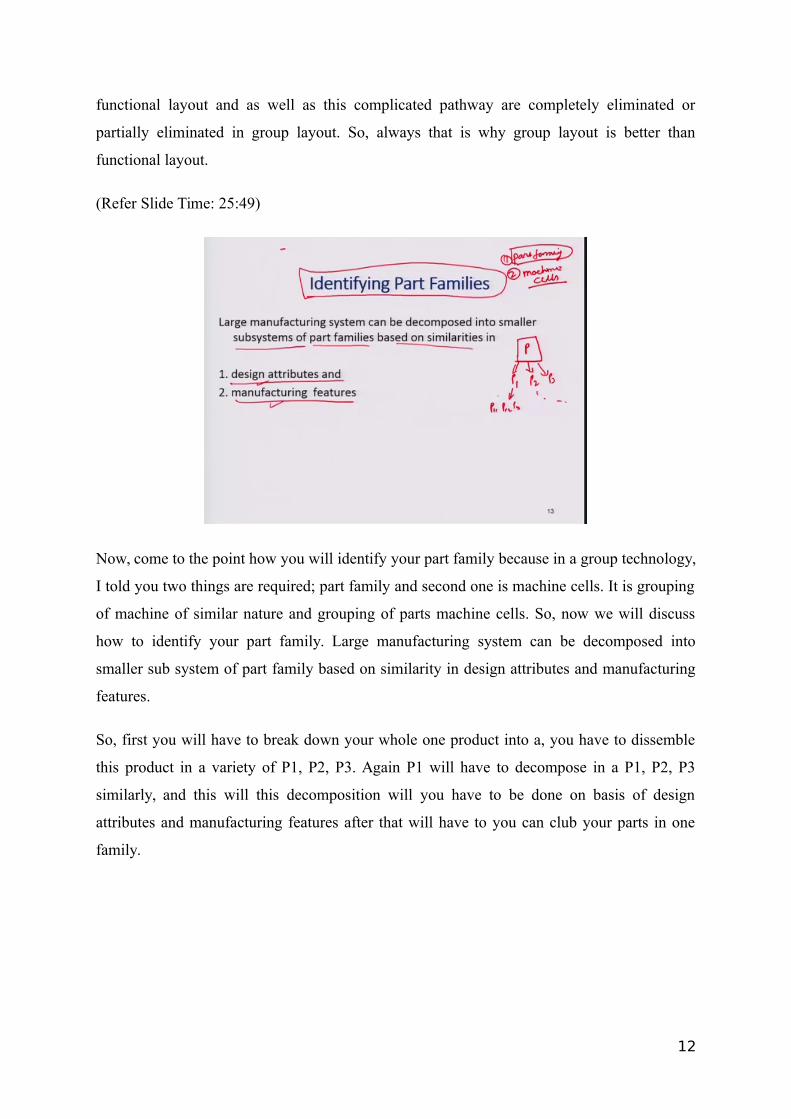
how to identify your part family. Large manufacturing system can be decomposed into
smaller sub system of part family based on similarity in design attributes and manufacturing
features.
So, first you will have to break down your whole one product into a, you have to dissemble
this product in a variety of P1, P2, P3. Again P1 will have to decompose in a P1, P2, P3
similarly, and this will this decomposition will you have to be done on basis of design
attributes and manufacturing features after that will have to you can club your parts in one
family.
12
(Refer Slide Time: 27:01)
So, design attributes, what are the design attributes? Part configuration for example round or
prismatic dimensional envelope length to diameter ratio, you can distinguish your parts using
L by D ratio, surface integrity. Surface roughness dimension tolerance suppose that we have
one ball one square and each have a surface roughness of 10 microns. So, we can club both
parts in one group. On basis of surface roughness, a material type suppose that this is made
by steel. Again it is made by steel, but shape is different, but material is same, so that we can
club both materials in a one family.
So, raw material state it depends on how you your planning to make a family of different
parts.
13
(Refer Slide Time: 27:59)
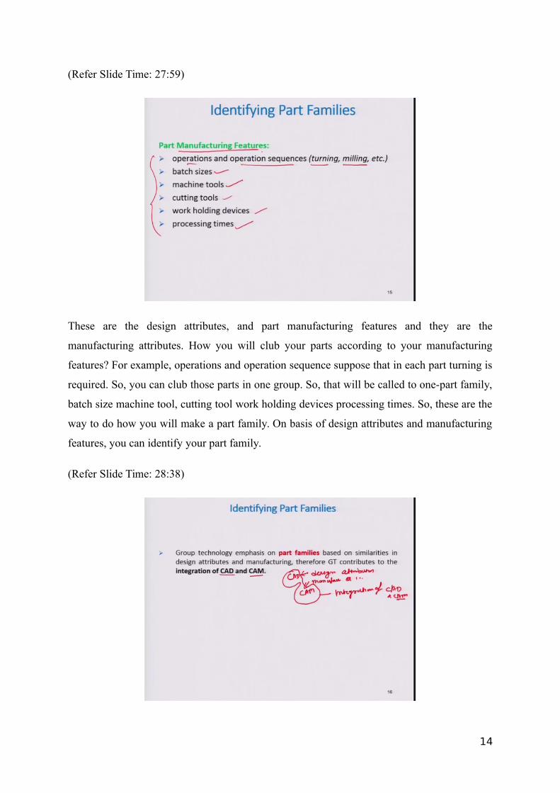
These are the design attributes, and part manufacturing features and they are the
manufacturing attributes. How you will club your parts according to your manufacturing
features? For example, operations and operation sequence suppose that in each part turning is
required. So, you can club those parts in one group. So, that will be called to one-part family,
batch size machine tool, cutting tool work holding devices processing times. So, these are the
way to do how you will make a part family. On basis of design attributes and manufacturing
features, you can identify your part family.
(Refer Slide Time: 28:38)
14
Group technology emphasis on part family based on similarities in design attributes and
manufacturing; therefore, GT contributes to the integration of CAD and CAM because you
are using design attributes as well as manufacturing attributes.
So, these attributed to CAD and this tend related to CAM. So, finally in actual case you are
clubbing CAM and CAM. So, that is why in a good technology technique, this is the
complete integration of CAD and CAM, computer aided designing and computer aided
manufacturing.
(Refer Slide Time: 29:30)
Now, I will tell you what is the part family. A part family is a collection having similar design
characteristics. Here you can see that for example, these also different parts, but it has a these
have similar characteristics. You will have to make a drilling of diameter in each part, so that
the other round in shape. So, you can club together in one family.
They are the manufacturing process. So, here you can see these are the parts part 1, part 2,
part 3, part 4 , part 5, part 6, but each parts required similar kind of process. Suppose you will
have to make drilling in each part. So, drilling will be done here. So, these parts are grouped
together on basis of manufacturing process. So, these are the part family equal to function of
P1, P2, P3, P4, P5, P6, on basis of your operation drilling is required. So, that in each part
that is why you have clubbed together on the basis of manufacturing process.
15
They are generally three methods of for identifying part family. First one is visual inspection,
second one is classification and coding and third one is production flow analysis. I will
discuss each method in detail.
(Refer Slide Time: 31:09)
First is visual inspection method. In this method what happens use photos or part prints
utilize subjective judgement here you can see they are the variety of parts are available, but
on basis of visualisation, one professional experience professionals are required for visual
inspection.
So, by using visual inspection, you can distinguish these parts in a variety of groups, so that
part family will be complete. Here you can see that these are the after visual inspection. There
two groups are G1 and G2 part family and G1 part G2 part family here, here the prismatic
parts; this one this one, this one and this one. So, these are the prismatic in shape and here
they are rotational part. So, these are clubbed together and they are clubbed together in
different. So, these are completely based on the visual inspection, but sometimes it is very
fast process, but if the variety of parts are available more, lot of parts are available in a
workshop, so it is very difficult for an engineer to distinguish all parts in different groups. So,
it is very well experienced person is required.
16
(Refer Slide Time: 32:50)
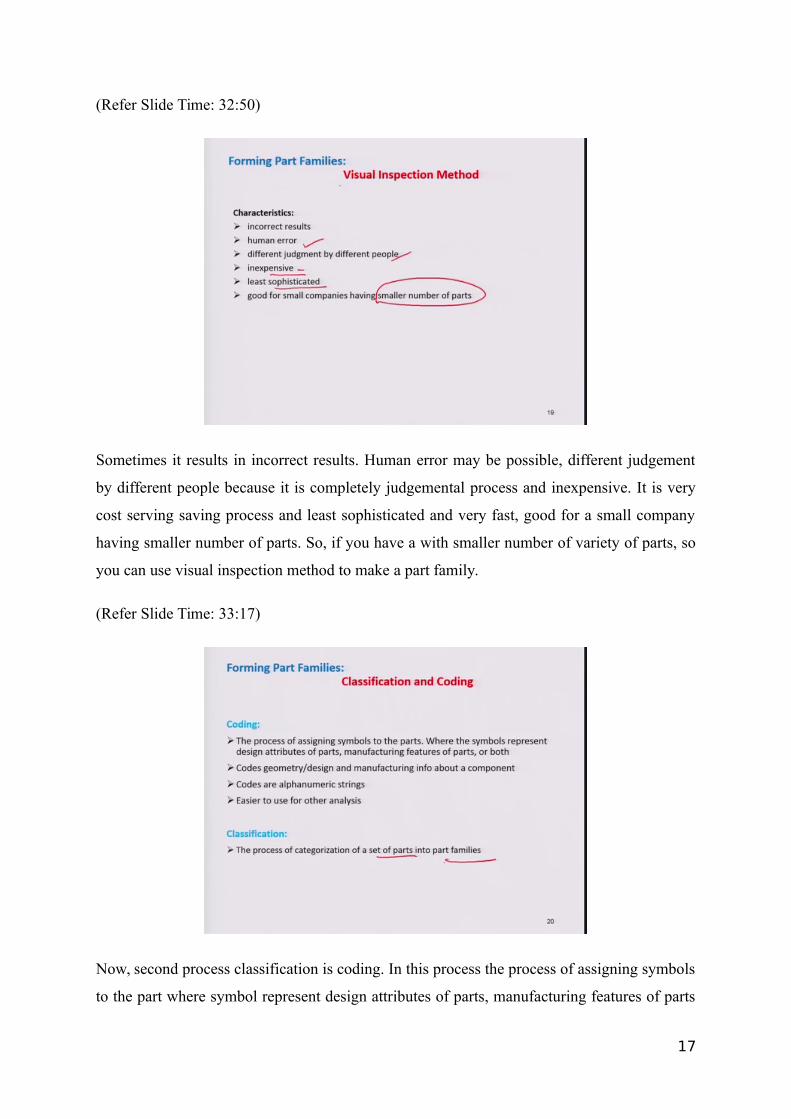
Sometimes it results in incorrect results. Human error may be possible, different judgement
by different people because it is completely judgemental process and inexpensive. It is very
cost serving saving process and least sophisticated and very fast, good for a small company
having smaller number of parts. So, if you have a with smaller number of variety of parts, so
you can use visual inspection method to make a part family.
(Refer Slide Time: 33:17)
Now, second process classification is coding. In this process the process of assigning symbols
to the part where symbol represent design attributes of parts, manufacturing features of parts
17
or both code. Geometry or design manufacturing info about a component codes are
alphanumeric string. Generally, if you have a variety of parts number of parts are available,
you are going to fabricate in your workshop.
So, each parts you can have to make a code for that, so that you can distinguish each part.
One part from another during codes and classification, the process of categorisation of a set
of part into part family is known as classification. After coding you can make a different
group, classify all code in different groups. So, those are known as part family.
(Refer Slide Time: 34:12)
It is a string of characters capturing information about an item. Three main types of coding
system structure are available. Classification coding first one is called monocode or
hierarchical structure. Second one is polycode or chain type structure and third one is mixed
mode structure.
18
(Refer Slide Time: 34:36)
Monocode here this is a code in which each digit amplifies the information given in the
previous digit and it is very difficult to construct. It is also known as hierarchical layout.
Coding system here you can see that first this one is suppose that one code is 3 2 x. Here
again this x, this one depends on this one, previous one.
So, it makes hierarchy for that and each code, one code is dependent on your previous code.
So, it is very difficult to construct and provide a deep analysis usually and it is generally used
for generally permanent information. So, monocode generally used in an engine. So, you can
find it in any automobile engine. There standard code is, the unique code is available there.
So, that is generally based on monocode.
19
(Refer Slide Time: 35:42)
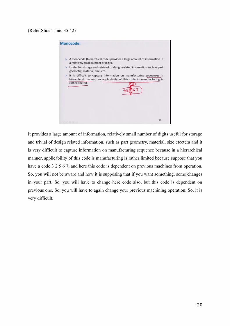
It provides a large amount of information, relatively small number of digits useful for storage
and trivial of design related information, such as part geometry, material, size etcetera and it
is very difficult to capture information on manufacturing sequence because in a hierarchical
manner, applicability of this code is manufacturing is rather limited because suppose that you
have a code 3 2 5 6 7, and here this code is dependent on previous machines from operation.
So, you will not be aware and how it is supposing that if you want something, some changes
in your part. So, you will have to change here code also, but this code is dependent on
previous one. So, you will have to again change your previous machining operation. So, it is
very difficult.
20
(Refer Slide Time: 36:40)
Another type code is Polycode. This code symbols are independent of each other. So, benefit
advantage of this code is, it is independent of each other and each digit in specific location of
the code describes a unique property of the work piece and it is very easy to learn and useful
infatuating situations. Even you can understand what the code is, meaning of that code.
So, Polycode suppose that one part has to travel through for operation and at each operation,
it signifies one code. So, one worker who does not belong to that work of, but if you will
provide a seat for coding, coding seat to him, so what will happen he can understand, this
code signifies to this operation. So, this part can be processed in this manner. So, here I will
be going to one example for that.
21
(Refer Slide Time: 37:40)
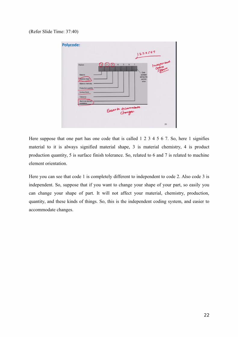
Here suppose that one part has one code that is called 1 2 3 4 5 6 7. So, here 1 signifies
material to it is always signified material shape, 3 is material chemistry, 4 is product
production quantity, 5 is surface finish tolerance. So, related to 6 and 7 is related to machine
element orientation.
Here you can see that code 1 is completely different to independent to code 2. Also code 3 is
independent. So, suppose that if you want to change your shape of your part, so easily you
can change your shape of part. It will not affect your material, chemistry, production,
quantity, and these kinds of things. So, this is the independent coding system, and easier to
accommodate changes.
22
(Refer Slide Time: 38:53)
Now, one other example you can see that their class of feature external shape, this is the digit
signified by one again in a. So, therefore, digits are available 1 2 3 4 and suppose that if you
are choosing external shape, so here if you want to make its cylindrical with deviations, you
just will take 1 2. So, this code will be 1 2. It means 1 3 means this part has an external shape
and cylindrical in shape and without any deviation. So, external shape can be either
cylindrical prismatic. So, that is why 1 and 2 are independent.
(Refer Slide Time: 39:40)
23
Now, third one is a hybrid structure and it includes both polycode monocode. So, here we can
see that is using it uses both type of codes; polycode and monocode. Also here you can see
Polycode are independent 1, 2, 3, 4, 5, 6, 7, 8, 9, 10, 11, 12, 13, 14, 15, and we have to
Monocode suppose that this one depends on 15, 12, 9, 6, and 3. So, you suppose that if I am
saying one code is alive in sequence, so you cannot say on which machine or previous
machine, either 9 or 6 it has processed.
So, you will have to go in detail for that to know on which because it depends on a previous
coding system. So, on which machine it has been processed again here similar kind of, so that
if you are mixed together both codes, then it will become a hybrid structure.
(Refer Slide Time: 40:45)
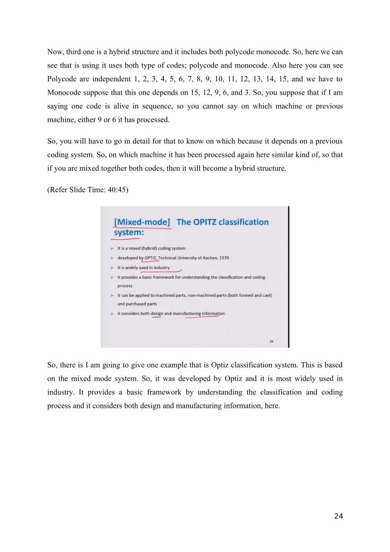
So, there is I am going to give one example that is Optiz classification system. This is based
on the mixed mode system. So, it was developed by Optiz and it is most widely used in
industry. It provides a basic framework by understanding the classification and coding
process and it considers both design and manufacturing information, here.
24
(Refer Slide Time: 41:07)
This is the general form of mixed code. In Optiz classification system here that three types of
codes generally used in this system form code, supplementary code and secondary code.
What is the form code? It focuses on part geometry dimensions and feature relevant to part
design and supplementary code includes information relevant to manufacturing, such as raw
material tolerance and surface roughness, and it is for example, it is signified by 6 7 8 9 and
the secondary code intended to identify the production operation type and sequence and it is
generally signified by A B C D, and it can be designed by the user firm to serve own need.
So, it is not a standard coding system. You can change your coding system according to your
requirement.
25
(Refer Slide Time: 42:04)
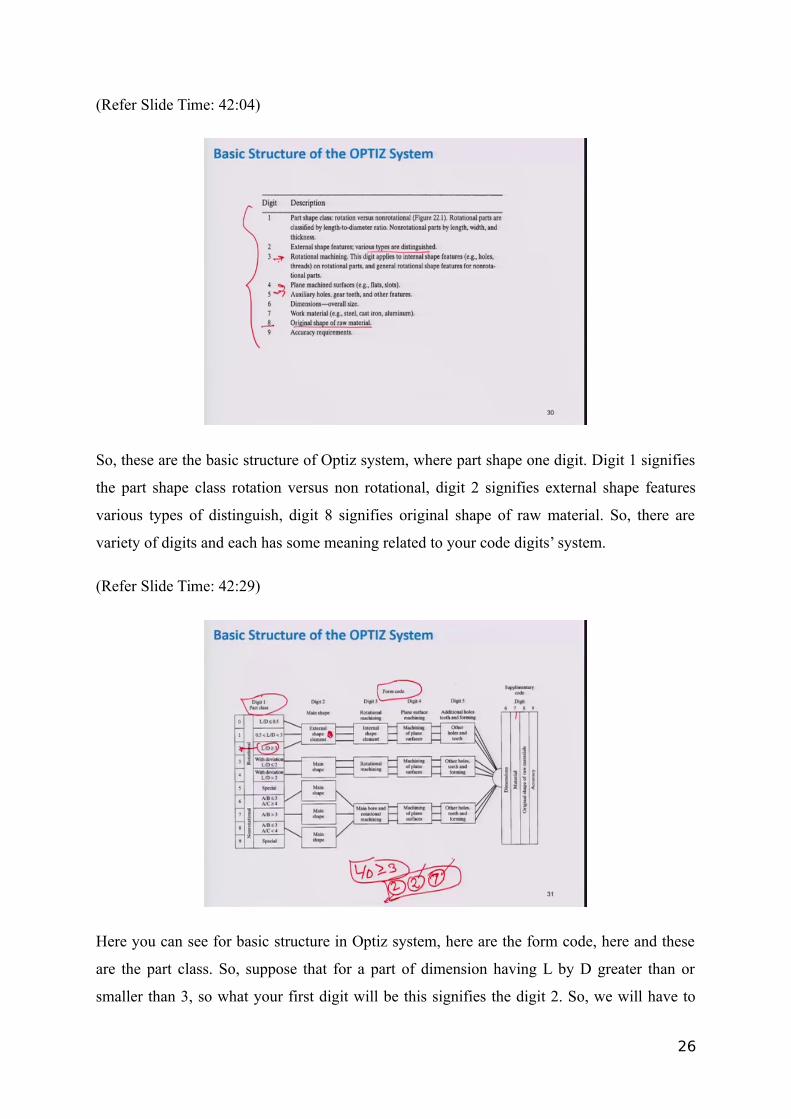
So, these are the basic structure of Optiz system, where part shape one digit. Digit 1 signifies
the part shape class rotation versus non rotational, digit 2 signifies external shape features
various types of distinguish, digit 8 signifies original shape of raw material. So, there are
variety of digits and each has some meaning related to your code digits’ system.
(Refer Slide Time: 42:29)
Here you can see for basic structure in Optiz system, here are the form code, here and these
are the part class. So, suppose that for a part of dimension having L by D greater than or
smaller than 3, so what your first digit will be this signifies the digit 2. So, we will have to
26
select D 2 and in a form code suppose that it requires external shape element, then it will go
through the internal shape element machining plane of surface other holes and teeth. So, it
signifies as a digit again 2.
Suppose that it will go external shape is required, again for material characterization, here
will have to go supplementary code. Then, again for material will have to suppose you have
taking materials type 7, so this code signifies what is the dimension of your part and in which
machine it will go through and what kind of material it is.
(Refer Slide Time: 43:33)
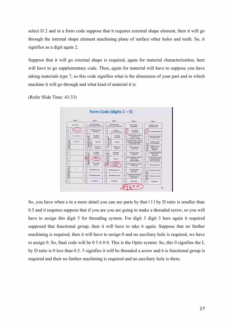
So, you have when a in a more detail you can see parts by that l l l by D ratio is smaller than
0.5 and it requires suppose that if you are you are going to make a threaded screw, so you will
have to assign this digit 5 for threading system. For digit 3 digit 3 here again it required
supposed that functional group, then it will have to take 6 again. Suppose that no further
machining is required, then it will have to assign 0 and no auxiliary hole is required, we have
to assign 0. So, final code will be 0 5 6 0 0. This is the Optiz system. So, this 0 signifies the L
by D ratio is 0 less than 0.5. 5 signifies it will be threaded a screw and 6 is functional group is
required and their no further machining is required and no auxiliary hole is there.
27
(Refer Slide Time: 44:35)
So, this is the form code 5, digit form code. There you can see here one example for that this
is the one rotational part design below determine the form code in Optiz part classification
and coding system. So, here you can see length is 1.5 and diameter is 1. So, L by D is equal
to 1.5. So, for L by D 1.5 you have to take one signifies digit with one digit. 1 is equal to digit
1. Again both ends stepped with the screw threaded one end. Here you can see that one end is
screwed and it is stepped in the shape. So, digit 2 is 5 here. You can see threaded, this
threaded to step into both end. So, one part is threaded.
So, you have to choose 5 again for internal shape part contains a through hole. There is one
hole through hole in this part. So, for through hole part, you will have to select here one
smooth or step to one end and no shape element functional group. So, you will have to
choose one again planar surface machining, no machining is required. So, 0 and auxiliary
holes, there no holes are there. So, again on digit 5, it signifies as 0.
So, final form code of this Optiz system is 1 5 1 0 0. So, this is the way how you will make a
form code for your part and this is very easy.
28
(Refer Slide Time: 46:02)
Another example you can see here L by D for two based on the pitch circle diameter of the
gear. So, fifth digit is 1 again. For external shape, there is steppes on one side with functional
groups. So, second digit is 3. Internal shape, the third digit is 1 because of a through hole
plane surface machining the four digit is 0 because there is no plane surface machining, there
is no any machining on outer side auxiliary holes and gear teeth. The fifth digit is 6 because
there are spur gear teeth on the part. Here you can see that the teeths are available. So, you
will have to design it with 6. So, final code will be 1 3 1 0 6 for the system.
(Refer Slide Time: 46:49)
29
Now, this is the third type of coding system. This is called Flow Analysis and product flow
analysis method for identifying part family and associated machine grouping based on the
required manufacturing process need for each part.
Here you can see that you are, these are the machines M1 M2 M3 M4 M5 M6 M7 and these
are the part family A B C D E F. So, what you are doing is, you are making a flow system,
you are giving 1 1 1 1 1. So, machines are either one suppose that for part family, it will be
machine on M1 and M5. So, you will have to assign it with 1 1. Rest of there will be either
you can write 0 or nothing. 0 0 again for part family B, it will be processed only on 1. So, rest
of the machine will be 0, you assign 0 0. So, it is a matrix method. Here you can represent
your flow system flow diagram in a matrix form. So, spot for example, for E machine, it is it
will have processed on machine 2 and machine 3. Now, after doing this which product will be
processed on which machine, then you can group together. Here you can see that CEI EI. So,
CEI and it will get it processed on 3 2 6 generally.
So, here these are the 1 1 1. Rest of will be 0. So, generally partially this CEIR one-part
family, on basis of machining operation. So, this is based on matrix mathematical matrix
form.
(Refer Slide Time: 48:51)
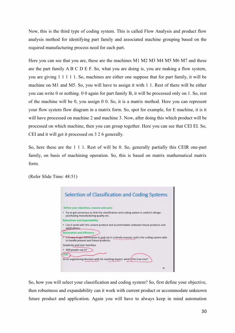
So, how you will select your classification and coding system? So, first define your objective,
then robustness and expandability can it work with current product or accommodate unknown
future product and application. Again you will have to always keep in mind automation
30
because every industry is moving towards to automation complete automation. It is easy to
get information in and out in a timely manner. So, that automatic retrieval system is an
incorporating industry.
So, you will have to make coding, make a code for accordingly will people use it or not cost
as an engineering decision with far reaching impact. What is the true cost one will have to
always keep in mind cost because every industry is situated only for making profit?
(Refer Slide Time: 49:36)
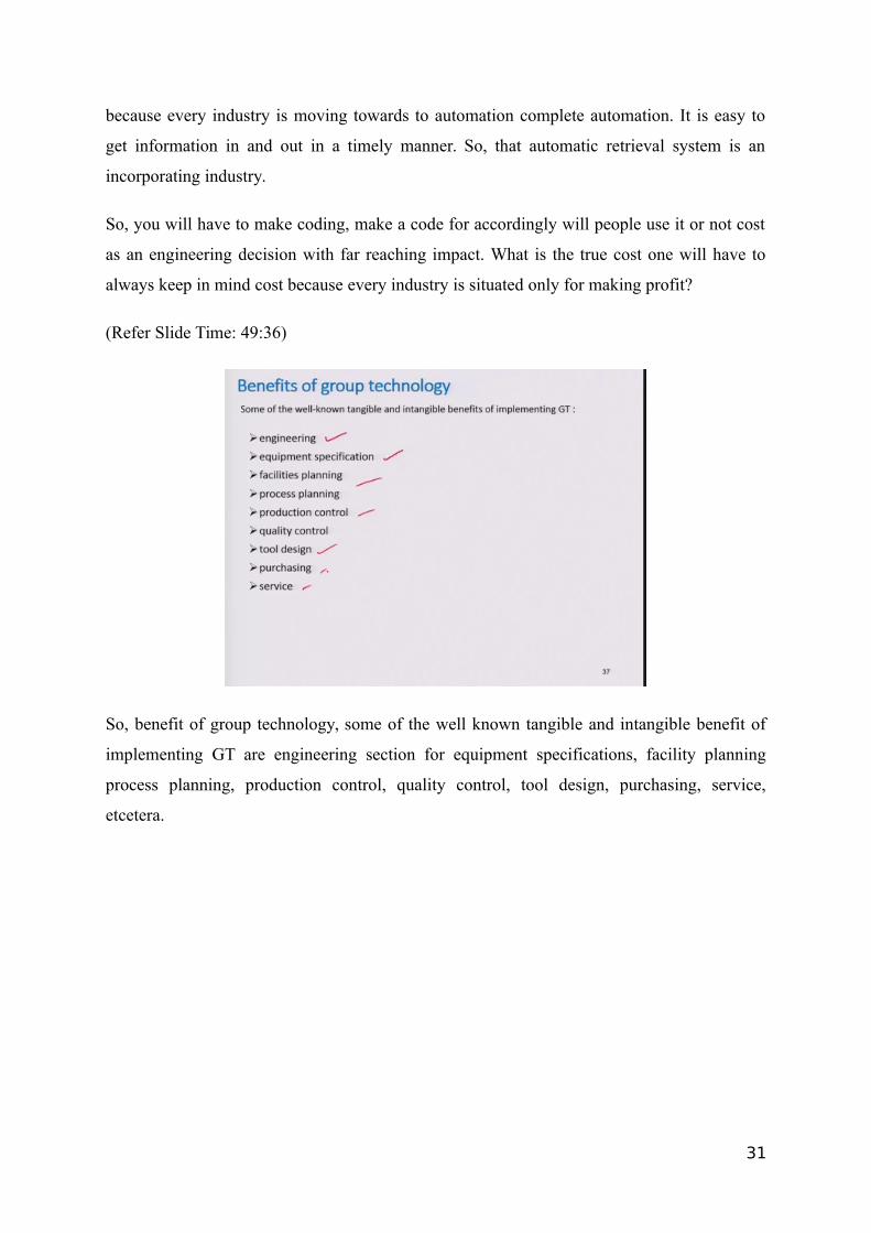
So, benefit of group technology, some of the well known tangible and intangible benefit of
implementing GT are engineering section for equipment specifications, facility planning
process planning, production control, quality control, tool design, purchasing, service,
etcetera.
31
(Refer Slide Time: 49:53)
So, engineering design if you are improving group technology in engineering design, so what
will happen is, reduction in a new part design, reduction in number of drawing through
standardization and reduction of number of similar part easy retrieval of similar function part
and identification of substitute parts and you can easily change your design because based on
your group technology if you are changing one part, so rest of it will be same, but only that
particular operation will get changed using a group technology techniques.
(Refer Slide Time: 50:22)
32
So, another is layout planning. So, you can plan your workshop in such a way that lead time,
age reduced and productivity will be higher than reduced metal handling effort because it
requires space as well as manpower and time.
(Refer Slide Time: 50:45)
Specification of equipment, tools, jigs and fixtures; you can standardization of equipment,
implementation of cellular manufacturing system and significant reduction in upfront cost
incurred in the release of new parts for manufacturing.
(Refer Slide Time: 51:02)
33
There are the benefit, other benefits in manufacturing process planning. The reduction in set
of time and production time, alternative routing leading to improve part routing and reduction
in number of machine operation and numerical control programming time. So, using group
technology process plan can be done.
(Refer Slide Time: 51:30)
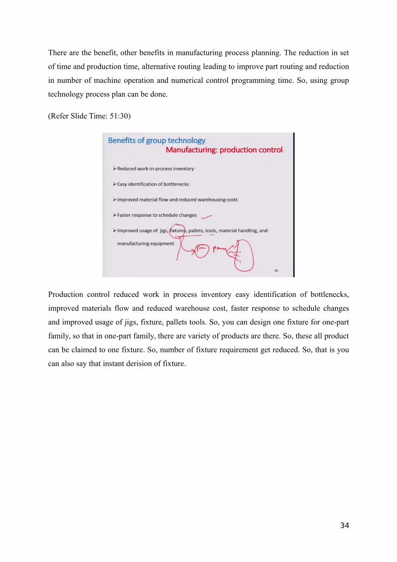
Production control reduced work in process inventory easy identification of bottlenecks,
improved materials flow and reduced warehouse cost, faster response to schedule changes
and improved usage of jigs, fixture, pallets tools. So, you can design one fixture for one-part
family, so that in one-part family, there are variety of products are there. So, these all product
can be claimed to one fixture. So, number of fixture requirement get reduced. So, that is you
can also say that instant derision of fixture.
34
(Refer Slide Time: 52:08)
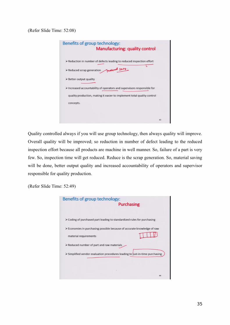
Quality controlled always if you will use group technology, then always quality will improve.
Overall quality will be improved; so reduction in number of defect leading to the reduced
inspection effort because all products are machine in well manner. So, failure of a part is very
few. So, inspection time will get reduced. Reduce is the scrap generation. So, material saving
will be done, better output quality and increased accountability of operators and supervisor
responsible for quality production.
(Refer Slide Time: 52:49)
35
Now, purchasing, coding of purchase part leading to standardized rule of purchasing
economics in purchasing possible because of accurate knowledge of raw metal requirements.
So, if you use standard coding system, so any buyer can check. You can check coding system
of that part and can say that this is made by this material. So, this is very easier. This will be
very easier for the buyer as well as the vendor. So, reduced number of parts and raw materials
simplified vendor evolution procedure leading to just in time purchasing.
Also, inventory will be also reduced using group technology because if in a functional layout
near every machine has some space to keep them to hold some parts, so those parts will get
finished after in serial manner. So, those kind of inventory will get reduced in a group
technology by customer service.
(Refer Slide Time: 53:55)
Accurate and faster cost estimates, you can estimate your cost of a product very efficiently
because you have planned everything. For that you have a well stabilized process layout. So,
that part will become this machine and it will get what is the lead time, how many workers
should be required and what will be each work machines efficiency machine production rate.
So, you can include those all factors, you can estimate your cost in a better way. Efficient
spare part management leading to better customer service and lower lead times, these are the
benefits of the group technology, but as well as a group technology has certain limitations
also because in every industry, you cannot.
36
Suppose that one industry is 50-year-old and they are using functional layout and suppose
that if you are going to incorporate group technology. So, what you will have to do you have
to move your all machines from here to there. So, it will take a lot of time manpower as well
as cost. So, sometimes worker will not be happy to change their work.
So, it is very difficult to, sometime it is very difficult to incorporate group technology
techniques in existing old industries, but it takes lot of money to incorporate these techniques,
but if you will look in a long term, then group technology will be better for your industry in a
long term, because it will suppose that you have invested a 10 million rupees for
incorporating group technology, so you cannot return back those moneys in within a year. So,
you will have to wait for that. So, overall group technology technique is a very good
technique to incorporate. So, it is generally actually you can say that it is a factory designing
layout designing system.
So, I am closing this module here and in the next module, I will discuss some other topics.