DEVELOPMENT OF STAINLESS STEEL TROLLEY NUR ADILAH BINTI AHMAD Report submitted in partial fulfilment of the requirements for the award of Diploma in Mechanical Engineering Faculty of Mechanical Engineering UNIVERSITI MALAYSIA PAHANG NOVEMBER 2008
Transcript
DEVELOPMENT OF STAINLESS STEEL TROLLEY
NUR ADILAH BINTI AHMAD
Report submitted in partial fulfilment of the requirements
for the award of
Diploma in Mechanical Engineering
Faculty of Mechanical Engineering
UNIVERSITI MALAYSIA PAHANG
NOVEMBER 2008
II
SUPERVISOR’S DECLARATION
I hereby declare that I have checked this project and in my opinion this project is
satisfactory in terms of scope and quality for the award of Diploma in Mechanical
Engineering
Signature
Name of Supervisor: RUSLI BIN GHANI
Position: INSTRUCTOR ENGINEER
Date:
Signature
Name of Panel:
Position:
Date:
III
STUDENT’S DECLARATION
I hereby declare that the work in this report is my own except for quotations and
summaries which have been duly acknowledged. The report has not been accepted
for any diploma and is not concurrently submitted for award of other diploma.
Signature
Name: NUR ADILAH BINTI AHMAD
ID Number: MB06009
Date: 16 OCTOBER 2008
IV
ACKNOWLEDGEMENTS
I would like to express my gratitude and appreciation to all those who gave
me the possibility to complete this report. Special thanks is due to my supervisor Mr.
Rusli bin Ghani whose help, stimulating suggestions and encouragement helped me
in all time of fabrication process and in writing this report.
I would also like to acknowledge with much appreciation the crucial role of
the staff in Mechanical Laboratory, who gave me a permission to use the mechanical
equipment and also the machine and to design the drawing and giving a permission
to use all the necessary tools in the laboratory.
Many thanks go to the all lecturer and supervisors who have given their full
effort in guiding the team in achieving the goal as well as their encouragement to
maintain our progress in track. My profound thanks go to all classmates, especially
to my friends for spending their time in helping and giving support whenever I need
it in fabricating my project.
V
ABSTRACT
This report presents about trolley that always been used especially in lab. This
trolley is a device which is important in order to ease transportation and to decrease
the load when we want to lift or transport heavy items from one place to another.
The idea of the fabricating of this trolley is based on student’s creativity. The
selection of suitable materials in the fabricating of this trolley is a loaded material
which has minimum weight, long life-span and can detain heavy load. Materials are
proposed for the fabrication of the trolley is a stainless steel material. In this report,
we’ll also be having more to the fabrication of this trolley.
VI
ABSTRAK
Laporan ini membentangkan tentang troli yang sering kali digunakan terutamanya di
dalam makmal. Troli merupakan suatu perkakas yang penting untuk memudahkan
pergerakan dan meringankan beban ketika hendak mengangkat atau mengubah
barang yang berat dari satu tempat ke satu tempat. Idea pembentukan troli ini
berdasarkan kreativiti pelajar sendiri. Pemilihan bahan yang sesuai untuk digunakan
bagi pembentukkan troli ini merupakan bahan yang mempunyai berat yang ringan,
jangka hayat yang tahan lama dan boleh menahan beban yang berat. Bahan yang
dicadangkan untuk pembentukkan troli ini merupakan material jenis stainless steel.
Dalam laporan ini juga akan lebih memfokuskan kepada pembentukkan troli.
VII
TABLE OF CONTENTS
Page
SUPERVISOR’S DECLARATION II
STUDENT’S DECLARATION III
ACKNOWLEDGEMENTS IV
ABSTRACT V
ABSTRAK VI
TABLE OF CONTENTS VII
LIST OF TABLES XI
LIST OF FIGURES XII
LIST OF SYMBOLS XIV
LIST OF ABBREVIATIONS XV
CHAPTER 1 INTRODUCTION
1.1 Project Synopsis 1
1.1.1 General Project Synopsis 1
1.1.2 Specific Project Synopsis 2
1.2 Problem Statement 2
1.3 Project Scope of Work 2
1.3.1 Literature Review 2
1.3.2 Sketching and Designing 2
1.3.3 Fabrication 2
1.3.4 Testing and Evaluation 2
1.4 Project Objectives 3
1.4.1 General Objectives 3
1.4.2 Specific Project Objectives 3
1.5 Project Flow Chart 4
VIIICHAPTER 2 LITERATURE REVIEW
2.1 Introduction 7
2.2 Paper Review 7
2.2.1 Trolley Types and Functions 7
2.3 Technical Review 8
2.3.1 Pictures 8
2.4 Basic Part 9
2.4.1 Wheels 9
2.4.2 Body 9
2.4.3 Handle Bar 9
2.5 Joining Method 9
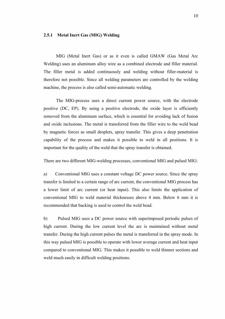
2.5.1 Metal Inert Gas (MIG) Welding 10
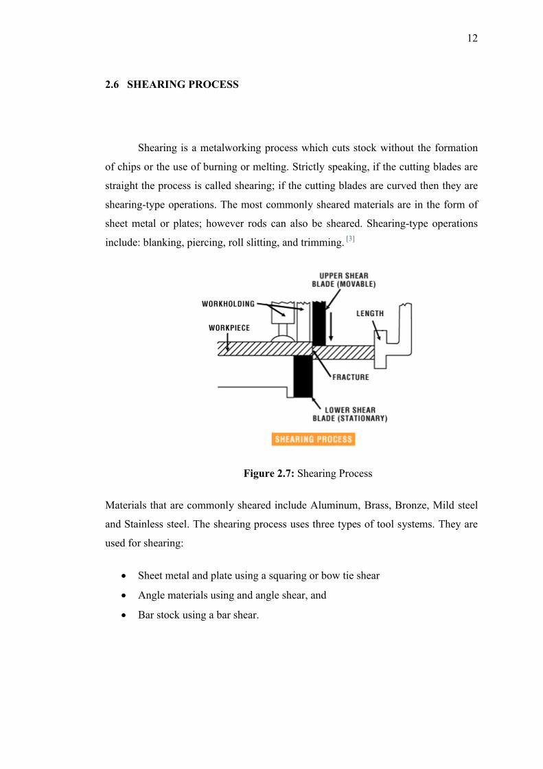
2.6 Shearing Machine 12
2.7 Bending Machine 13
2.8 Drilling 14
2.8.1 Drill Press 14
2.9 Grinding Process 15
CHAPTER 3 METHODOLOGY
3.1 Introduction 17
3.2 Design 17
3.2.1 Strength 17
3.2.2 Ergonomic Factors 17
3.2.3 Suit to Environment 17
3.3 Drawing 18
3.3.1 Sketching 18
3.3.2 CAD Drawing 18
3.4 Design Specification 18
3.5 Sketching Drawing Selection 18
3.5.1 Sketching 1 19
3.5.1 Sketching 2 19
IX3.5.3 Sketching 3 20
3.6 Sketching Selection 20
3.6.1 Suggested Selection 20
3.7 Computer Aided Design Drawing 21
3.8 Overview of the Design 21
4.8.1 Design Description 21
3.9 Calculation 22
3.9.1 Engineering strain on a sheet during bending 22
3.9.2 Bend Allowance 23
3.9.3 Bend Radius 23
3.9.4 Bend Force 23
3.9.5 Cutting Force 24
3.10 Fabrication Process 24
3.10.1 Process Involve 25
3.10.2 Material of The Project 25
3.10.3 Step by Step Process 27
3.10.4 Fabrication Process 28
CHAPTER 4 RESULTS AND DISCUSSION
4.1 Introduction 32
4.2 Project Problem 32
4.2.1 Literature Review 32
4.2.2 Design and Sketching 32
4.2.3 Fabrication Process 32
4.2.4 Material Preparation 32
4.2.5 Budget Preparation 32
4.3 Problem During Fabrication Process 33
4.3.1 Material (Stainless Steel) 33
4.3.2 Welding Process 33
4.3.3 Bending Process 34
XCHAPTER 5 CONCLUSSION AND RECOMMENDATION
5.1 Introduction 35
5.2 Conclusion 35
5.3 Recommendation 36
5.3.1 Facilities 36
5.3.2 Student Budget 36
5.4 Future Work 36
REFERENCES38
APPENDICES39
XI
LIST OF TABLES
Table No. Page
1 Project Schedule 4
XII
LIST OF FIGURES
Figure No. Page
1.1 Project Flow Chart 8
2.1 Hospital Trolley 8
2.2 Full-storage Trolley 8
2.3 Luggage Trolley 8
2.4 Lightweight Portable 8
2.5 Metal Inert Gas (MIG) Welding 9
2.6 Schematic of Metal Inert Gas (MIG) Welding 11
2.7 Shearing Process 12
2.8 Shearing Machine 13
2.9 Bending Machine 14
2.10 Drill Press Machine 15
2.11 Grinder 16
3.1 Sketching 1 19
3.2 Sketching 2 19
XIII
3.3 Sketching 3 20
3.4 Sketching 4 20
3.5 CAD Drawing 21
3.6 Explode CAD Drawing 22
3.7 Sheet Plate 26
3.8 Hollow Steel 26
3.9 Wheel 26
3.10 Cutting sheet plate using shearing machine 28
3.11 Bending Process 29
3.12 Cutting sheet plate for more shape using vertical saw 29
3.13 Drilling Process 30
3.14 Welding process using MIG welding 30
3.15 Finishing step using grinder 31
4.1 The result of the high voltage 33
4.2 Spring back in Bending 34
XIV
LIST OF SYMBOLS
e Strain
σ Stress (N/m2)
E Young's Modulus = σ /e (N/m2)
y Distance of surface from neutral surface (m).
R Radius of neutral axis (m)
I Moment of Inertia (m4 - more normally cm4)
Z Section modulus = I/ymax(m3 - more normally cm3)
M Moment (Nm)
W Total load on beam (kg ) or (N as force units)
F Concentrated force on beam (N)
S Shear Force on Section (N)
L Length of beam (m)
x Distance along beam (m)
XV
LIST OF ABBREVIATIONS
AL Aluminium
AISI The American Iron and Steel Institute
ASTM American Society for Testing and Materials
CAD Computer Aided Design
MIG Metal Inert Gas Welding
PPE Personal Protective Equipment
UHMWPE Ultra high molecular weight polyethylene
SMAW Shielded metal arc welding
UMP Universiti Malaysia Pahang
1
CHAPTER 1
INTRODUCTION
1.1 PROJECT SYNOPSIS
1.1.1 General Project Synopsis
The project involves designing and fabricating a Trolley. As the Diploma final
year project allocates the duration of 1 semester, this large man-hour project
therefore requires significant efforts of the students to participate. Basically the
entire trolley could be divided into three stages, which are concept review and
development, designing and fabrication.
The trolley is equipped by using stainless steel 304 2B material which include,
rectangular plate steel, round hollow steel, and wheels in manufacturing process by
perform MIG welding to joint the parts and etc. The advantages of the proposed
trolley to be developed can be seen to be moved such that, man are offered to make
their task easier since the trolley will facilitate them to transfer heavy items for
instance, computer and etc.
The process of development is initiated from designing the shape of the trolley
by considering the function as well. In order to produce user friendly product that is
suitable to the consumer, consideration to the ergonomic factor is taken into account.
It involves the measurement process before the materials are cut into pieces before
joined together.
2
1.1.2 Specific Project Synopsis
My project title is Development of Stainless Steel Trolley. The project
involves small analysis of the Trolley frame body and fabrication of the trolley itself
with concerns regarding strength, durability, ergonomic factor, and convenience.
Test need to be done to verify the strength of the trolley right before the fabrication
process to avoid material and fund wasting. The projects prerequisites are Static,
Dynamic and Strength of Material. Overall, the project will meet acquire skills of
design, analysis, and fabrication.
1.2 PROBLEM STATEMENT
The concept of the trolley is to facilitate man for loading items. This trolley
will primarily help staff especially members of Faculty of Mechanical Engineering
to load and unload heavy items that’s need trolley for convenience. Members are
facing problem while the need to bring things from one place to another due to
unavailability of trolley. Thus, with the development of this trolley, it is hope that it
can contribute to give them ideas how to overcome problem in loading items by
choose the better way in facilitate their routine at University Malaysia Pahang
especially for Faculty of Mechanical Engineering staff.
1.3 PROJECT SCOPE OF WORK
1.3.1 Literature Review: Valuable data are searched and gathered. Considering
the shape of the trolley in terms of its complexity and method to produce.
1.3.2 Sketching & Designing: Sketching and designing using Solidwork software
in creating the design of the trolley.
1.3.3 Fabrication: Fabricate and produce the trolley by using all necessary
manufacturing process such as welding, cutting, grinding and etc.
1.3.4 Testing & Evaluation: Simulate the mechanism of the trolley produce is in
line with the expected function to be.
3
1.4 PROJECT OBJECTIVES
1.4.1 General Objectives
Diploma final year project objective is to practice the knowledge and skill
of the student that have been gathered before in solving problem using academic
research, to born an engineer that have enough knowledge and skill. This project
also important to train and increase the student capability to get know, research,
data gathering, analysis making and then solve a problem by research or scientific
research.
The project also will educate the student in communication like in a
presentation and educate them to defend their research in the presentation. The
project also will generate students that have capability to make a good research
report in thesis form or technical writing. This project also can produce and train
student to capable of doing work with minimal supervisory and more independent in
searching, detailing and expanding the experiences and knowledge.
1.4.2 Specific Project Objectives
The project objectives are to design trolley that is suite to its application
especially for loading items and to minimize the manufacturing cost by minimize the
complexity of the trolley and simulate the material used with cheaper material but
having high strength and endurance.
4
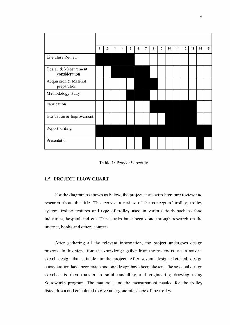
Table 1: Project Schedule
1.5 PROJECT FLOW CHART
For the diagram as shown as below, the project starts with literature review and
research about the title. This consist a review of the concept of trolley, trolley
system, trolley features and type of trolley used in various fields such as food
industries, hospital and etc. These tasks have been done through research on the
internet, books and others sources.
After gathering all the relevant information, the project undergoes design
process. In this step, from the knowledge gather from the review is use to make a
sketch design that suitable for the project. After several design sketched, design
consideration have been made and one design have been chosen. The selected design
sketched is then transfer to solid modelling and engineering drawing using
Solidworks program. The materials and the measurement needed for the trolley
listed down and calculated to give an ergonomic shape of the trolley.
Presentation
Report writing
Evaluation & Improvement
Fabrication
Methodology study
Acquisition & Material preparation
Design & Measurement consideration
Literature Review
151413121110987654321
5
Next, after the needed material is listed, acquisition step take places. There are
only a few materials that need to buy such as wheels. Some of the needed material is
well-prepared by the university.
After all the parts needed had been gathered, the project proceeds to next step
that is fabrication process. The finished drawing and sketching is used as a reference
by following the measurement and the type of materials needed. The fabrication
process that involved is cutting, welding, and others. If all the parts had been
processed, the parts are joined together to produce full-scaled trolley. Here come the
testing and evaluation process. The trolley will be test to see if it fulfills the
requirement such as ergonomic aspect, safety, strength and manoeuvrability. During
the testing, if problem occur such as malfunction or unstable platform, the trolley
will step back to the previous process, where the error is fixed. The trolley is
expected to have an error that may cause the part to be re-designed and re-fabricate
again.
After all the parts had been joined together, here comes the last phase of
process that is data discussion. In data discussion, the draft report and all the related
articles are gathered and hand over to the supervisor for error checking. The finish
product will be compared with the report to make sure that there is no mistake on
both project and report.
After the product and the report had been approved by the supervisor, the
report is rearrange and print out to submit at the supervisor, the project coordinator
and faculty of Mechanical Engineering. In this stage, the final presentation was also
being prepared and waited to be present.
6
Figure 1.1: Project Flow Chart
Literature Study
Acquisition & PreparationOf material
Fabrication / Improvement
Need Modification
Presentation & Submission
Designing:
•Sketching & Design
•Material Listing
•Measurement
Testing & Evaluation
Report Preparation
Data Discussion
Yes
No
7
CHAPTER 2
LITERATURE REVIEW
2.1 INTRODUCTION
The trolley is a mechanism that allowed man to transfer their heavy items
such as computers, files and etc to other places. It’s help man to do their work
without having a problem due to the heavy loading. Its also helps to reduce pain in
waist, back, hand and feet. No mater how light the loading is, people usually will
suffocate a large pain in their body if lifting the items in many times. So, this is
when the people rely upon a trolley that can do items transferring many times with
just a little effort. From the statement above conclude that the trolley playing a major
role as an items transferring mechanism for people without having a problem of
doing that. A trolley also functioned as a helper to people to hold items orderly
while transferring between rough lands.
2.2 PAPER REVIEW
2.2.1 Trolley types and functions
(i) Food Trolley: a small table on wheel or castor that typically used to convey
foods and drinks.
(ii) Supermarket trolley: a large metal basket or frame on wheels used for
transporting heavy and unwieldy items.
(iii) Luggage trolley: a frame on wheel used to transporting heavy luggage at
airport or railway station.
8
(iv) Hospital trolley: a tray on wheels for transporting icebox for organ, surgery
items and others.
(v) Full-storage trolley: a cabinet on wheel for keeping workshop tools and
transporting them easily.
(vi) Lightweight portable trolley: a platform on wheels for transporting wide and
heavy items in workshop, office, warehouse and etc.