eel e*3 Z '.+ ~% ;i,+ R. & M. No. 3663 MINISTRY OF DEFENCE AERONAUTICAL RESEARCH COUNC1L REPORTS AND MEMORANDA Boundary-Layer Suction to Eliminate Corner Separation in Cascades of Aerofoils By R. E. PEACOCK University Engineerin~ Department, Cambridge LONDON: HER MAJESTY'S STATIONERY OFFICE 1971 PRICE £1"25 NET
Transcript
eel
e*3
Z
' . + ~ % ;i,+ R. & M. No. 3663
MINISTRY OF DEFENCE
AERONAUTICAL RESEARCH COUNC1L REPORTS AND MEMORANDA
Boundary-Layer Suction to Eliminate Corner Separation in Cascades of Aerofoils
By R. E. PEACOCK
University Engineerin~ Department, Cambridge
LONDON: HER MAJESTY'S STATIONERY OFFICE
1971
PRICE £1"25 NET
Boundary-Layer Separation in Cascades of Aerofoils
Summary. Results of a series of experiments are presented in which the corner separation existing at the junction
between a cascade sidewall and a moderately loaded compressor blade in cascade was eliminated by means of a boundary-layer suction technique. The relationship which was investigated between suction flow required for controi of the corner separation and the suction slot geometry is also reported.
It was found that with careful positioning of the suction slot, bleed flows of less than 0.1 per cent of a half channel mass flow could result in elimination of the separation region. As a result, stagnation pressure profiles at the cascade trailing-edge plane became much more uniform and the high loss core of fluid that would otherwise be shed downstream and hence into succeeding blade rows of a multi-row turbo-machine was eliminated.
Section 1.
2.
3.
4.
5.
6.
7.
8.
9.
LIST OF CONTENTS
Introduction
Apparatus
The Experimental Techniques
The Experimental Programme
Discussion
Initial Corner Control Experiments
Optimisation of Slot Length
Optimisation of Slot Width
Yawmeter Traverses with Various Slot Geometries
*Replaces A.R.C. Report No. 27 291.
10. Slot Optimisation on the 40 degree Camber Cascade
Conclusions
Acknowledgements
References
Detachable Abstract Cards
1. Introduction.
If the two-dimensional boundary layer of a fluid is turned in the plane of the boundary layer it is known that a three-dimensional flow is created in that fluid due to the re-distribution of pressure gradients. This three-dimensional flow is generally referred to as distributed secondary circulation (Ref. 1) and, in the case of a cascade of aerofoils or the blade row of a compressor, grows progressively through the channel due to the presence of the boundary layers upon the sidewalls or annulus walls.
For some years research has been pursued at the Cambridge University Engineering Department into the behaviour of air moving through cascades. Various workers (e.g. Armstrong (Ref. 2), Louis (Ref. 3)) have found associated with the distributed secondary circulation a core of high loss fluid at the corner where the convex surface of the aerofoil intersects the sidewall. Louis (Ref. 3) has shewn that the location of this core of fluid is due to separation of the boundary layer in the corner.
As early as 1948 Griffith of Rolls-Royce Ltd. suggested that end losses could be reduced by applying boundary-layer suction at the corner between the convex surface and the annulus wall of a compressor. In 1949 Malley (Ref. 4) conducted an experiment using this boundary-layer suction technique in a cascade of aerofoils and the results indicated a substantial improvement in the cascade performance. The im- portant effect of the presence of a suction slot without the use of suction flow was not appreciated at this time, so the comparative results of Ref. 4 may not be entirely valid. This work was not, however, continued until 1964 due to the mechanical complication of using such a system in a compressor and also due to the disappointing results gained from compressor tests using a system of boundary layer suction through peripheral slots. In 1964 Stratford (Ref. 5) redeveloped the arguments for controlling the corner flow and conducted a series of experiments on a compressor cascade of 2.25in span and 1.00in chord at 0.6 Mach number.
A detailed investigation at Cambridge into the growth of secondary distributed circulation in a large scale cascade channel had provided an ideal starting point for examining the control of corner separation. In parallel with the Rolls-Royce Ltd. work and with their encouragement a series of experiments was embarked upon in which it was attempted to eliminate the corner separation of boundary-layer suction and investigate the parameters affecting the control of this corner separation. This report describes these experiments.
2. Apparatus.
The low speed cascade wind-tunnel of the Cambridge University Engineering Department described in Ref. 6 was used throughout.
Two cascades were used each of a C.4 profile with a 6 in. chord, 6 in. pitch, 18 in. span and nine blades to each cascade. One cascade, with a 30 ° circular arc camber was set at a nominal incidence of - l ° and the other cascade with a 40 ° circular arc camber was set at a nominal incidence of - 8 °.
In order to accommodate the boundary-layer suction mechanism, a liner was fitted upstream of the cascade as far as the contraction, the tunnel width thus being reduced by 1-5 in. to 16.5 in. By fitting plates in the cascade, the sidewall created by the liner was carried through the cascade giving an aspect ratio of 2.75. One of the plates was so made that its convex contour was depressed by 0.126 in. giving
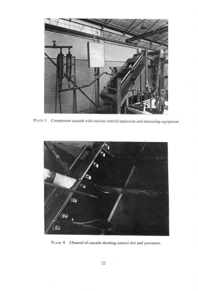
a slot in the corner when fitted into the cascade (Plate 4). To the back of this plate was fixed a suction manifold manufactured in resin (Plates 1 and 2). Through this manifold air was sucked by means of a small capacity suction niotor connected by appropriate lengths of piping. The quantity of air thus evac- uated was measured by the use of Rotameters. The general view of the rig in Plate 3 shows all the relevant features except the suction motor which is out of the picture to the left. It is seen that the corner selected for the control experiment was in one of the central channels.
Measurements of the behaviour of the air were made by using a five hole spherically headed probe (Ref. 7) the head of which is shown in Plate 4 together with the suction slot in the background. The method of support for this probe is seen in Plate 3. The measurements were taken by using micromanometers, whose range was 13 in. methylated spirits and which were able to record pressure changes of 0.0005 in. (Foreground right, Plate 3).
3. The Experimental Techniques. Three techniques for observing and measuring the flows in the channels of the cascades were used.
(i) The Five Hole Yawmeter: This device was used for measuring data to give the velocity, static pressure and two angles of flow, which describe fully a three-dimensional time independent motion. A description of the yawmeter and its method of use appear in Ref. 7.
(ii) Flow Visualisation: Very close to the bounding walls of the channels the accuracy of the yawmeter was reduced. At these walls a technique of surface flow visualisation, whereby a visual tracer was suspended in a liquid painted on the walls, was extensively used. Of a large number of mixtures tried, the most successful was one of eight parts paraffin to one of linseed oil (by volume) with about 2 cm. 3 of titanium dioxide added to every 45 cm. a of fluid. The best results were obtained when the surfaces under observation were finished in gloss black.
(iii) Wooltufts: To a very limited extent a wooltuft was used on the end of a probe in order to get a better understanding of the flow in the corner. This was particularly useful in following the rapid attenu- ation in a spanwise direction of the flow pattern close to the wall.
In order to gain an understanding of the flow field in any set of circumstances, it was found to be of the greatest use to investigate the flow initially with the surface visualisation method and then as necessary with the wooltuft, before using the yawmeter.
4. The Experimental Programme. All of the experiments described were carried out at an inlet Reynolds Number of 2.0 × 10⁵. It will be
seen from Ref. 6, which reports tests on the same cascades, that for this value of Reynolds Number the cascades operate at a high efficiency at the blade mid-height. The initial observations, which had no corner boundary-layer control, were made before the liner reducing the aspect ratio was fitted. There was then a small but insignificant variation in the aspect ratio during the programme.
The first tests on the 30 ° camber cascade in which the slot was 100 per cent of the chord length and the full designed width of 0.126 in. were made in order to assess the relationship between suction flow rate and the air behaviour in the corner. A wide range of suction rates was investigated together with, in one instance, the effect of having the slot present with no suction flow. At suction rates of 1.3, 0-51 and 0.32 per cent of the total flow in one half of the channel a detailed investigation of the floor r~gime at the trailing-edge plane was carried out using the yawmeter.
A second phase of the investigation was to determine the variation with slot geometry of the suction flow rate to eliminate separation, firstly by optimising on slot length and then, at optimum slot length, optimising on slot width. Traverses of the exit plane were made at the optimum slot length at suction flows of 0-38 and 0"32 per cent and at the minimum slot width with the minimum flow rate possible at which control of the corner flow could be maintained.
As a check on this work, a similar but somewhat abbreviated series of tests was carried out using a 40 ° camber cascade.
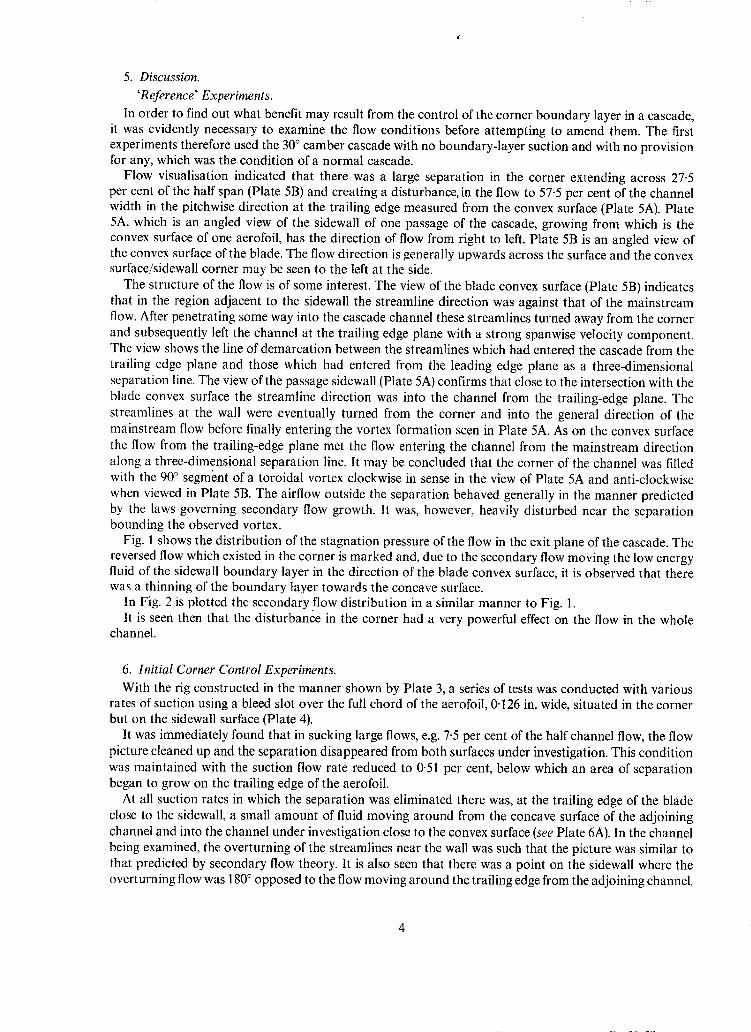
5. Discussion. 'Reference' Experiments.
In order to find out what benefit may result from the control of the corner boundary layer in a cascade, it was evidently necessary to examine the flow conditions before attempting to amend them. The first experiments therefore used the 30 ° camber cascade with no boundary-layer suction and with no provision for any, which was the condition of a normal cascade.
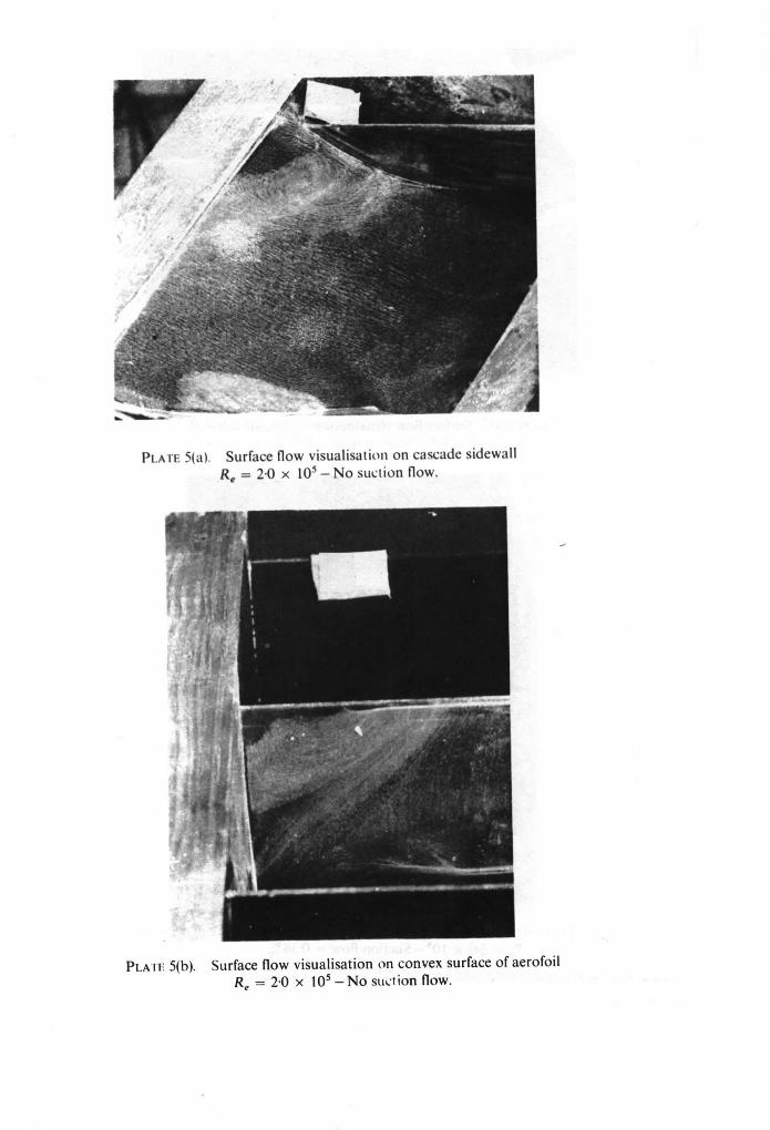
Flow visualisation indicated that there was a large separation in the corner extending across 27-5 per cent of the half span (Plate 5B) and creating a disturbance, in the flow to 57-5 per cent of the channel width in the pitchwise direction at the trailing edge measured from the convex surface (Plate 5A). Plate 5A, which is an angled view of the sidewall of one passage of the cascade, growing from which is the convex surface of one aerofoil, has the direction of flow from right to left. Plate 5B is an angled view of the convex surface of the blade. The flow direction is generally upwards across the surface and the convex surface/sidewall corner may be seen to the left at the side.
The structure of the flow is of some interest. The view of the blade convex surface (Plate 5B) indicates that in the region adjacent to the sidewall the streamline direction was against that of the mainstream flow. After penetrating some way into the cascade channel these streamlines turned away from the corner and subsequently left the channel at the trailing edge plane with a strong spanwise velocity component. The view shows the line of demarcation between the streamlines which had entered the cascade from the trailing edge plane and those which had entered from the leading edge plane as a three-dimensional separation line. The view of the passage sidewall (Plate 5A) confirms that close to the intersection with the blade convex surface the streamline direction was into the channel from the trailing-edge plane. The streamlines at the wall were eventually turned from the corner and into the general direction of the mainstream flow before finally entering the vortex formation seen in Plate 5A. As on the convex surface the flow from the trailing-edge plane met the flow entering the channel from the mainstream direction along a three-dimensional separation line. It may be concluded that the corner of the channel was filled with the 90 ° segment of a toroidal vortex clockwise in sense in the view of Plate 5A and anti-clockwise when viewed in Plate 5B. The airflow outside the separation behaved generally in the manner predicted by the laws governing secondary flow growth. It was, however, heavily disturbed near the separation bounding the observed vortex.
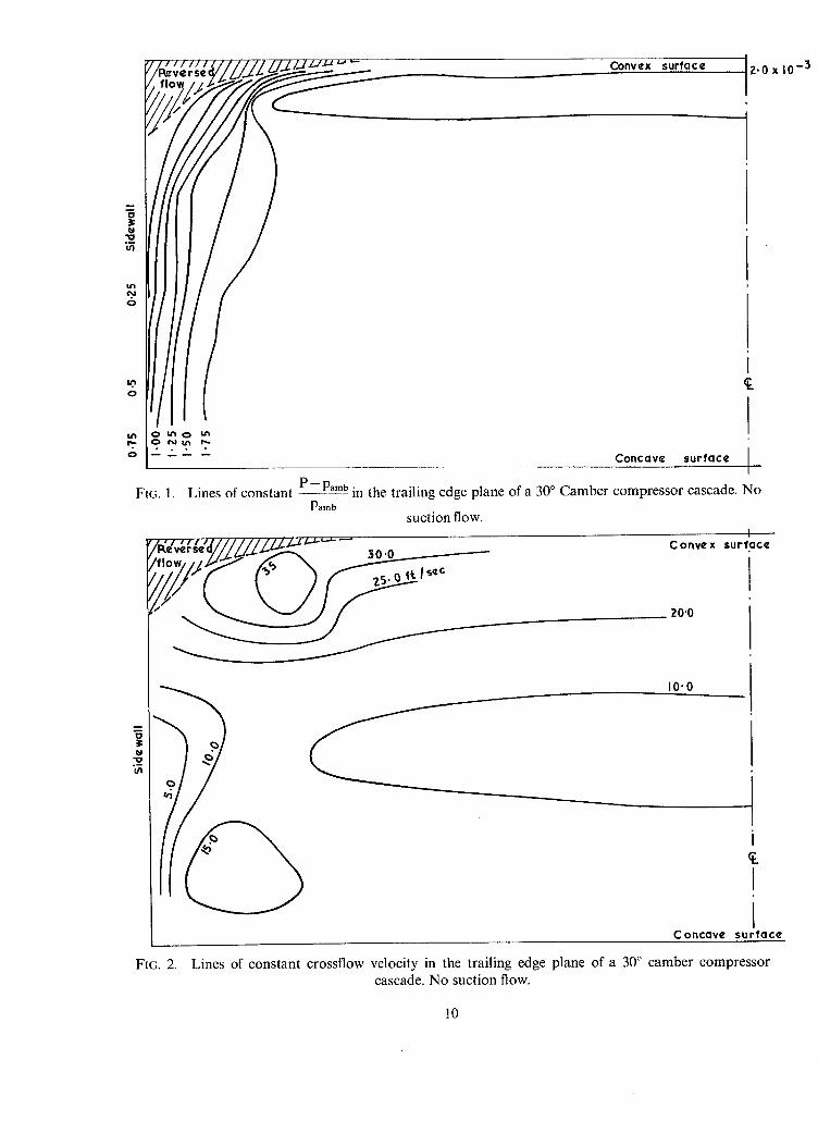
Fig. 1 shows the distribution of the stagnation pressure of the flow in the exit plane of the cascade. The reversed flow which existed in the corner is marked and, due to the secondary flow moving the low energy fluid of the sidewall boundary layer in the direction of the blade convex surface, it is observed that there was a thinning of the boundary layer towards the concave surface.
In Fig. 2 is plotted the secondary flow distribution in a similar manner to Fig. 1. It is seen then that the disturbance in the corner had a very powerful effect on the flow in the whole
channel.
6. Initial Corner Control Experiments. With the rig constructed in the manner shown by Plate 3, a series of tests was conducted with various
rates of suction using a bleed slot over the full chord of the aerofoil, 0.126 in. wide, situated in the corner but on the sidewall surface (Plate 4).
It was immediately found that in sucking large flows, e.g. 7.5 per cent of the half channel flow, the flow picture cleaned up and the separation disappeared from both surfaces under investigation. This condition was maintained with the suction flow rate reduced to 0.51 per cent, below which an area of separation began to grow on the trailing edge of the aerofoil.
At all suction rates in which the separation was eliminated there was, at the trailing edge of the blade close to the sidewall, a small amount of fluid moving around from the concave surface of the adjoining channel and into the channel under investigation close to the convex surface (see Plate 6A). In the channel being examined, the overturning of the streamlines near the wall was such that the picture was similar to that predicted by secondary flow theory. It is also seen that there was a point on the sidewall where the overturning flow was 180 ° opposed to the flow moving around the trailing edge from the adjoining channel.
From this saddle point, there sprang two three-dimensional separation lines, one of which moved into the channel and was swallowed in the suction slot and the other being shed downstream. Wooltuft experiments indicated that this picture attenuated very rapidly in the spanwise direction and in general, at the trailing edge plane, evidence of the flow entering from the adjoining channel had disappeared at a distance of 1.0 per cent of the half channel span from the wall.
On the convex surface at high suction flow rates, the picture was that of the mainstream flow having a small spanwise component moving the fluid towards the centreline of the cascade (see Plate 6B). At about 4-2 per cent of the half span from the sidewall a well-defined three-dimensional attachment line ran parallel to the comer. To one side of this attachment line the attached flow moved across the blade in a generally streamwise direction but with the spanwise component already mentioned. To the other side (the sidewall side) the flow again had a spanwise component, but this took it into the suction slot where it was bled away.
Two main effects were observed in reducing the suction flow rate. Firstly, the flow away from the sidewall at the convex surface tended to increases its spanwise component
at the trailing edge. This increased with reducing suction until just ahead of the trailing edge and to the mainstream side of the attachment line the velocity appeared to have a spanwise component only. With a further reduction in bleed flow these streamlines took on a reversed flow component before being washed downstream. The flow thus entrained on to the blade surface from behind the trailing edge met that which had progressed normally across the blade surface at a three-dimensional separation line. It is of interest to note that in such a region the wall shear stress never goes to zero and that the separation line and reversed flow are not coincident.
Secondly, there was an effect associated with the length of the bleed slot. The slot, which ran over the convex surface ofthc blade, had imposed upon its length the pressure distribution along the blade section. The pressure at the slot towards the maximum lift point of the blade was therefore less than that towards the trailing edge. With high suction flows, and hence a large pressure drop across the slot, this was of no consequence. At very low suction flows however, the suction pressure was not less than that at the maximum lift point of the blade. This resulted in a reversed flow in the slot, fluid being swallowed towards the trailing edge, some of which moved forward in the slot and reappeared on the blade surface at the maximum lift point. With careful control, this would take the form of a closed separation bubble and it was possible to have the condition where both distinct types of separation could exist separately at the same time.
In practice, as the bleed flow was reduced, the separation at the trailing edge appeared very shortly after the separation bubble in the corner, though once they were both in existence they grew rapidly with reducing suction flow to unite into the familiar corner separation.
With no suction flow at all, but with the slot present, the picture returned very closely to that of the 'Reference' experiments except that the separation zone was enlarged. This was a direct result of the presence of the bleed slot and the chordwise reversed flow within it.
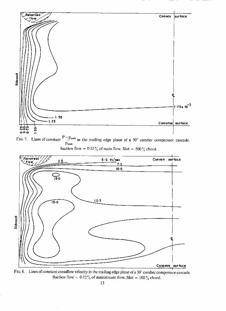
Yawmeter traverses were made of the exit plane of the channel for three different bleed flow rates, 1.3, 0.51 and 0.32 per cent of the half channel flow. These values were chosen because at a suction flow rate of 1.3 per cent the separation was well controlled, at 0.51 per cent the separation was just controlled and at 0-32 per cent there was some separation in the corner. Results from the case of a bleed flow of 1-3 per cent are plotted in Figs. 3 and 4; those from the 0-51 per cent bleed flow case are plotted in Figs. 5 and 6, and those from the case of a suction flow 0-32 per cent are plotted in Figs. 7 and 8.
Examining first the case of the bleed flow rate of 0.51 per cent, Fig. 5 shows the pattern of the stagnation pressure distribution. It is seen that there is no evidence that the flow had separated in the corner. Com- pared with the case for no bleed flow the velocity field was extremely flat, and the only large velocity variations appeared in the sidewall boundary layer. It is again noted that this boundary layer thickened towards the convex surface/sidewall corner, as a result of the distributed secondary circulation which moved the low energy air within the boundary layer towards this corner. This was of course the over- turning effect. The secondary circulation flow pattern (Fig. 6) was again fairly flat and, to some extent the crossflows appeared to vary with the stagnation pressure. Towards all surfaces the crossflow velocities
tended to zero except in the corner near the bleed slot. In this region they passed through a minimum before growing again as the slot was closely approached--evidence of the suction in the corner.
Increasing the bleed flow rate to 1.3 per cent had the effect of slightly reducing the sidewall boundary- layer thickness towards the suction corner (Fig. 3) so that the picture of a boundary layer thickening in this direction was not so obvious. The crossfiow velocities (Fig. 4) were generally reduced in the channel (Fig. 6) and a similar trough in the crossflow profiles close to the suction corner led eventually to a higher crossflow rate deep in the corner, commensurate with the higher suction flow employed.
It has already been mentioned that a reduction in the bleed flow rate below 0.51 per cent resulted in corner separation. Tests at the flow rate of 0.32 per cent confirmed this and in Fig. 7 it is seen that a re- versed flow spreading across the span of the blade was already present. The uniformity of the velocity field which characterised the flow when the corner separation was eliminated was also beginning to deteriorate at this suction rate.
A comparison of the pitchwise averaged stagnation pressure across the span (Fig. 9) shows that corner suction to eliminate separation improved the fullness of the curves towards the wall. The existence of a small amount of separation depressed the curve towards that of the 'reference' experiment whilst suction flows in excess of that required to eliminate the separation, improved the fullness of the curve as a result of thinning the sidewall boundary layer in the region of the sidewall/convex surface corner. The character- istic thinning of the sidewall boundary layer close to the sidewall/concave surface which was a result of the action of the secondary flow tended to mask the effect of the corner separation, demonstrated in Fig. 9.
7. Optimisation of Slot Length. It was noted from flow visualisation that, towards the trailing edge, flow from the adjacent channel was
entering the slot. In the region of the maximum lift point of the blade section, it was seen also that under certain conditions some fluid could re-emerge from the slot. It was therefore decided to optimise the slot length to reduce the suction flow necessary to eliminate separation.
The result of foreshortening the slot by blanking off at the trailing edge was the growth and separation of the boundary layer in the corner downstream of the slot. It was therefgre recognised that a slot extending to the trailing edge was essential if control of the corner flow was desired.
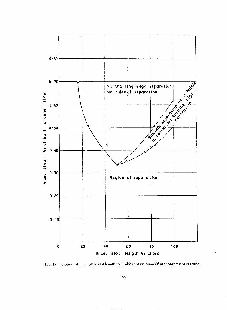
Fig. l0 shows results of a series of experiments in which the slot length was shortened by blanking off from the blade leading edge. The curves show the minimum suction rate required to eliminate separation from any slot length. With a full length slot, at a bleed flow of less than 0.51 per cent, the flow separated in the corner area. At a flow between 0-51 and 0.64 per cent there was no trailing edge separation, but a bubble of separation was present in the corner. At flow levels greater than 0.64 per cent a separation free picture resulted both on the sidewall and across the span of the blade. An initial reduction in the slot length had no effect on the picture but with further reductions a progressively smaller amount of bleed flow was required to eliminate the separation, until a well defined optimum was reached with a 50 per cent length slot and a flow of 0.38 per cent. Further reduction of the slot length called for an increased flow to control the flow. An explanation for this is that with the very short slot length the corner boundary layer was moving in a region of generally adverse pressure gradient and its tendency to separate was very great. This could only be eliminated by creating a region of favourable pressure gradient locally in the corner through the removal of larger masses of air. The further that the bleed slot was removed from the area where the boundary layer was tending to separate, the greater was the necessary suction flow in order that the influence of the favourable pressure gradient would be fed far enough upstream.
8. Optimisation of Slot Width.
The original slot was made 0.126 in. wide, based on the assumption that about 1 per cent of the main- stream flow would possibly be needed to eliminate the reversed flow in the corner. As a means of assessing any relationship between the slot width and the required bleed flow several liners, reducing the slot width by various amounts, were fitted to the optimum length slot of 3 in. The results are seen in Fig. 1 I. The narrower the slot the less was the required bleed flow and a straight line
relationship resulted between the flow required to eliminate separation and the slot width. The line does not, however~ pass through the origin. With a zero slot width, a finite amount of suction would still be required. This is compatible with the fact that with no slot there was a reversed flow in the corner.
To investigate the point reached by extrapolating the straight line to the zero slot width condition, it is helpful to consider the inlet boundary layer to the cascade. A region at the inner part of the boundary layer had a stagnation pressure less than the outlet static pressure of the cascade. From the boundary-layer profile the volume flow entering the cascade whose stagnation pressure was less than the cascade outlet static pressure may be calculated. By referring to Plate 6A, the last streamline moving along the sidewall which passed into the convex surface/sidewall corner could be traced back to the inlet plane. This then gave the proportion of the total boundary layer entering the cascade which was swept into the corner, ignoring the effects of skewing within the boundary layer. With the available results this yields a value of 0.086 per cent.
This very simple method appears to overestimate the suction flow required by about 0-014 per cent of the half channel flow. No account is taken of skewing within the boundary layer or of boundary-layer turbulent mixing in the channel, both of which would tend to reduce this figure.
9. Yawmeter Traverses with Various Slot Geometries.
It has been shown that an optimum Need flow requirement exists with a slot length of 50 per cent chord length. Yawmeter traverses were carried out using the full slot width (0-126 in.) with 50 per cent chord length and also with a 50 per cent chord length slot of the smallest width obtainable.
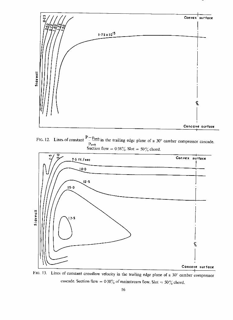
With the former geometry traverses were completed with corner bleed flows of 0-38 per cent and 0.32 per cent, these values corresponding with the cases where reversed flow was just eliminated and a small amount of reversed flow was present. Results from the 0"38 per cent case are shown in Figs. 12 and 13. In Fig. 12 it is seen that the velocity field in the main stream was essentially flat, no separation existing in the corner and that the side-wall boundary layer thickened up in the characteristic manner. The crossflow profile was also very even. Figs. 14 and 15, which carry the results of the 0.32 per cent suction case, show a rather similar picture except in the corner where a region of reversed flow was observed and with it, slight distortion both of the stagnation pressure profiles and the cross flow profiles. A comparison with Figs. 7 and 8, the case of a similar bleed flow on a 100 per cent length slot, indicates the gain in correct siting of the slot in the presence of a separation.
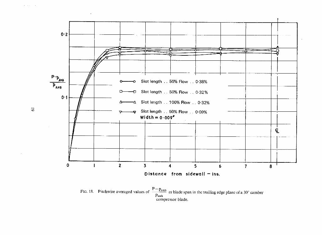
The pitchwise averaged stagnation pressure profiles for these cases is illustrated in Fig. 18. For com- parison, the curve for 0.32 per cent flow with a 100 per cent slot is also included.
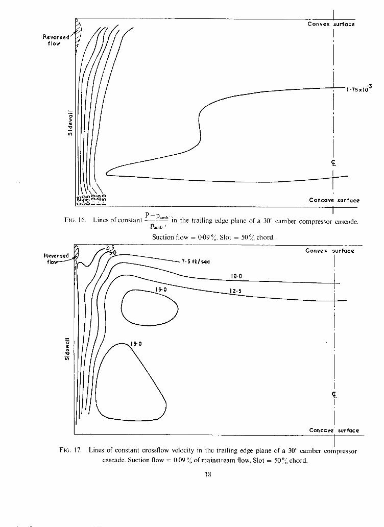
Corresponding to the lowest plotted point in Fig. 11 a further yawmeter traverse was completed with a slot width of 0.009 in. and a bleed flow of 0.09 per cent. In this case, although the spanwise picture on the convex surface showed no sign of flow reversal, the stagnation point on the sidewall had moved up- stream and there appeared to be a considerable reversed flow at the sidewall. Results are shown in Figs. 16 and 17. It is seen that there was a small amount of reversed flow very close to the wall in the corner due to spilling from the adjacent channel.
10. Slot Optimisation on the 40 ° Camber Cascade.
In order to check the preceding work on a cascade of different geometry a similar, though abbreviated, investigation was made using a 40 ° camber cascade also at an inlet angle of 50 °.
Slot length was optimised in the same manner as for the 30 ° camber cascade and the results when plotted (Fig. 19) are very similar. The same well-defined optimum exists at the position of a 50 per cent chordal length slot where it was necessary to suck 0.34 per cent of the half channel airflow to eliminate the corner separation.
This figure is slightly lower than that for the 30 ° camber cascade and is due to the full slot width of the 40 ° camber cascade being 0.119 in. compared with 0.126 in. for the former.
11. Conclusions. For compressor blades of modest loading the separation which exists in the convex surface/sidewall
corner of a cascade can be eliminated by using boundary-layer suction. With optimum siting of a very narrow slot bleed flows of less than 0.1 per cent result in control of the flow. The beneficial results are much flatter velocity profiles in the cascade and the elimination of the high loss core which usually exists in the corner.
Acknowledgements. The work was made possible by a Rolls-Royce Research Contract and it is a pleasure to record not only
the financial help, but the equipment and advice that were readily available. Grateful acknowledgement is made to The Cambridge University Engineering Department where the
experiments were carried out. The author is also indebted to Mr. H. G. Rhoden of the Cambridge University Engineering Department
for his interest and encouragement throughout the work.
No. Author(s) 1 W.R. Hawthorne
2 W.D. Armstrong
3 J .F . Louis ..
4 H .M. Malley ..
5 B.S. Stratford ..
6 H .G. Rhoden ..
7 R.E. Peacock ..
REFERENCES
Title, etc. Quarterly Journal of Mechanics and Applied Mathematics. Vol. III, Part 3 (Sept. 1955).
The non-uniform flow of air through cascades of aerofoils. Ph.D. Thesis (1954), Cambridge University.
Lines of constant P - Pamb in the trailing edge plane of a 30 ° camber compressor cascade. P a m b
Suction flow = 0-32~ of main flow. Slot = 100~ chord•
5.0 ft./s¢c 7-5
I 0 . 0
Convex surface
L IZ.5
J ¢.
Concave s u r f a c e
FIG. 8. I
Lines of constant crossflow velocity in the trailing edge plane of a 30 ° camber compressor cascade. Suction flow 0.32 o/ = /o of mainstream flow. Slot = 100~o chord•
13
0"2
P - ~AHB
~)AMB
0"1
A z//J
,/
0
~ m m ~
Z~
O
E l
L_
0 N o s u c t i o n
ZX S l o t l e n g t h . . 1 0 0 % : F l o w . . 0 . 3 2 %
o S l o t length . . . 1 0 0 % : F l o w . . 0 - 5 1 %
o S l o t l e n g t h • • 1 0 0 % : F l o w . . 1 . 3 %
Z 3 4 5 6 7 8
¢,1
0 m
U C "CJ 0 0 U
0 u,,s
m " 0 • eJ L
~ o U
ul
0 0 U c
D i s t a n c e f rom s i d e w a l l - ins.
FIG. 9. Pitchwise averaged values of P - Pamb
- - v s blade span in the trailing edge plane of a 30 ° camber Pamb
compressor cascade•
U~
1 "00 - - - ~
I 0 " 9 0 I
I
O 80
• 0-70 0
c
o O. 60 t -
O
,I--
0.s0
!
0
0 4 0
O. 30 - -
0 0
I t
! I =
I I ! I I ,
m I ! t
l
l I )No t ra i l i ng edge separation! i
No sidewall separation i J = i !
, i i
/ - - - )/Siaewall separation]
,/1 seen as a bubble m +/ | in corner. No i
/ trai l ing edge / separat ion I /
/ / = i
Region of separation m
Z0 40 60 80 100 Bleed s lo t length */o chord
FIG. 10. Optimisation of bleed slot length to inhibit separation. 30 ° arc compressor cascade.
3 " 0
0
m
u
_~ Z" 0
o
!
O
g
~ 1"0
/
Z
Slot width -- °k of blade pi tch
FIG. 11. Optimisation of bleed slot width to inhibit separation using a 50~ chord length slot.
0
'10 °~ u)
1.75 x 10 .3
I C o n v e x s u r f a c e '
I
C o n c a v e s u r f a c e
FIG. 12. Lines of constant - - - -
I
P--Pamb in the trailing edge plane of a 30 ° camber compressor cascade. Pamb
Suction flow = 0.38~. Slot = 5 0 ~ chord.
0
"0 °~ (/1
0
.5
7.5 f t / s e c
15-0
1 C o n v e x surface
Concave s u r ' f a c ¢
I FIG. 13. Lines of constant crossflow velocity in the trailing edge plane of a 30 ° camber compressor


![~n Vertxca]~ Descent - Cranfield Universitynaca.central.cranfield.ac.uk/reports/arc/rm/2735.pdfA brief check on the validity of applying this characteristic curve to a helicopter rotor](https://static.documents.pub/doc/80x56/5e6a6d6e86783478684a5d9e/n-vertxca-descent-cranfield-a-brief-check-on-the-validity-of-applying-this.jpg)


