37
ECE 546 – Jose Schutt-Aine 1 ECE 546 Lecture -12 MNA and SPICE Spring 2014 Jose E. Schutt-Aine Electrical & Computer Engineering University of Illinois [email protected]
| Date post: | 30-Dec-2015 |
| Category: |
Documents |
| Upload: | arabella-cox |
| View: | 219 times |
| Download: | 1 times |
ECE 546 – Jose Schutt-Aine 1
ECE 546Lecture -12
MNA and SPICESpring 2014
Jose E. Schutt-AineElectrical & Computer Engineering
University of [email protected]

ECE 546 – Jose Schutt-Aine 2
The Node Voltage method consists in determining potential differences between nodes and ground (reference) using KCL
1 1 1 2 0m
A B C
V V V V V
Z Z Z
For Node 1:
Nodal Analysis

ECE 546 – Jose Schutt-Aine 3
22 1 2 0n
C D E
V VV V V
Z Z Z
For Node 2:
1 2
1 1 1 1 1m
A B C C A
V V VZ Z Z Z Z
Rearranging the terms gives:
1 2
1 1 1 1 1n
C C D E E
V V VZ Z Z Z Z
Defining:1 1 1 1 1
, , , ,A B C D EA B C D E
G G G G GZ Z Z Z Z
Nodal Analysis

ECE 546 – Jose Schutt-Aine 4
Rearranging the terms gives:
1
2
A B C C A m
C C D E E m
G G G G G VV
G G G G G VV
The system can be solved to yield V1 and V2.
Nodal Analysis

ECE 546 – Jose Schutt-Aine 5
1 1 1 25 0 10 450
10 5 2 2
V V j V V
j j
For Node 1:
For Node 2: 2 1 2 2 02 2 3 4 5
V V V V
j j
Nodal Analysis

ECE 546 – Jose Schutt-Aine 6
Rearranging the terms gives:
1 2
1 1 1 1 5 0 10 45
10 5 2 2 2 2 10 5V V
j j j j
1 2
1 1 1 10
2 2 2 2 3 4 5V V
j j j
Nodal Analysis

ECE 546 – Jose Schutt-Aine 7
1
2
1 1 1 1 50 05 2 4 4 5
50 901 1 1 154 4 2 2
j V
V
j
Nodal Analysis
[Y] [v]=[i]

ECE 546 – Jose Schutt-Aine 8
1
10 0.25
25 0.75 0.5 13.5 56.324.7 72.25
0.45 0.5 0.25 0.546 15.95
0.25 0.75 0.5
j jV V
j
j
1
0.45 0.5 10
0.25 25 18.35 37.833.6 53.75
0.45 0.5 0.25 0.546 15.95
0.25 0.75 0.5
j
jV V
j
j
Nodal Analysis - Solution

ECE 546 – Jose Schutt-Aine 9
1 23 05
V V 2 32 1 2 0
5 10 5
V VV V V
3 2 3 05 10
V V V
MNA Formulation
Node 1:
Node 2:
Node 3:
ECE 546 – Jose Schutt-Aine 10
1
2
3
0.2 0.2 0 3
0.2 0.5 0.2 0
0 0.2 0.3 0
V
V
V
1
2
3
0.2 0.2 0 3
0 0.3 0.2 3
0 0 0.25 3
V
V
V
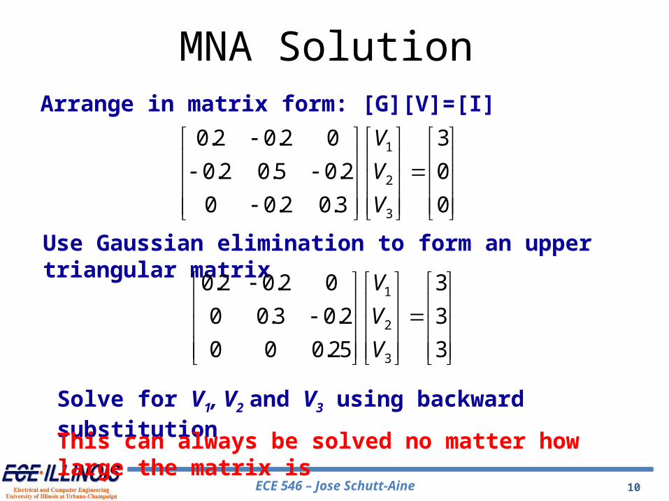
Solve for V1, V2 and V3 using backward substitution
Arrange in matrix form: [G][V]=[I]
Use Gaussian elimination to form an upper triangular matrix
This can always be solved no matter how large the matrix is
MNA Solution

ECE 546 – Jose Schutt-Aine 11
Established platform
Powerful engine
Source code available for free
Extensive libraries of devices
New device installation procedure easy
Why SPICE ?
ECE 546 – Jose Schutt-Aine 12
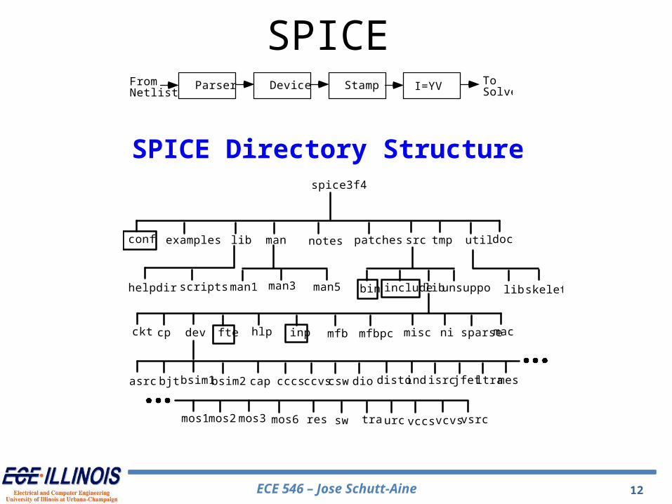
spice3f4
conf examples lib doc
helpdir scripts
bjt
utiltmppatches srcnotesman
man1 man3 man5 unsuppobin include lib skeleton
ckt cp dev fte hlp inp mfb mfbpc misc ni sparse mac
asrc bsim1 bsim2 cap cccs ccvs csw dio disto ind isrc mes
mos1
ltrajfet
mos2 mos3 mos6 res sw tra urc vccs vcvs vsrc
lib
Parser StampFromNetlist
I=YVDevice ToSolver
SPICE Directory Structure
SPICE

ECE 546 – Jose Schutt-Aine 13
Symbol Description Value Units
Ldrawn Device length (drawn) 0.35 mm
Leff Device length (effective) 0.25 mm
tox Gate oxide thickness 70 A
Na Density of acceptor ions in NFET channel 1.0 1017 cm-3
Nd Density of donor ions in PFET channel 2.5 1017 cm-3
VTn NFET threshold voltage 0.5 V
VTp PFET threshold voltage -0.5 V
l Channel modulation parameter 0.1 V-1
g Body effect parameter 0.3 V1/2
Vsat Saturation velocity 1.7 105 m/s
mn Electron mobility 400 cm2/Vs
mp Hole mobility 100 cm2/Vs
kn NFET process transconductance 200 mA/V2
kp PFET process transconductance 50 mA/V2
Cox Gate oxide capacitance per unit area 5 fF/mm2
CGSO,CGDO Gate source and drain overlap capacitance 0.1 fF/mm
CJ Junction capacitance 0.5 fF/mm2
CJSW Junction sidewall capacitance 0.2 fF/mm
Rpoly Gate sheet resistance 4 W/square
Rdiff Source and drain sheet resistance 4 W/square
MOS SPICE Parameters
ECE 546 – Jose Schutt-Aine 14
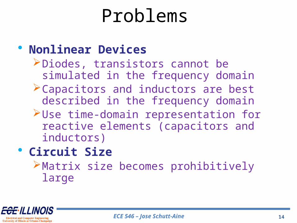
• Nonlinear DevicesDiodes, transistors cannot be simulated in the
frequency domainCapacitors and inductors are best described in the
frequency domainUse time-domain representation for reactive elements
(capacitors and inductors)• Circuit SizeMatrix size becomes prohibitively large
Problems
ECE 546 – Jose Schutt-Aine 15
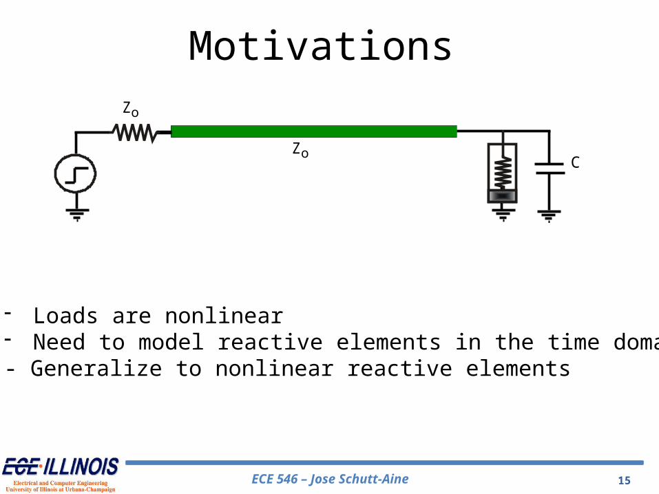
- Loads are nonlinear- Need to model reactive elements in the time domain- Generalize to nonlinear reactive elements
Zo
ZoC
Motivations
ECE 546 – Jose Schutt-Aine 16
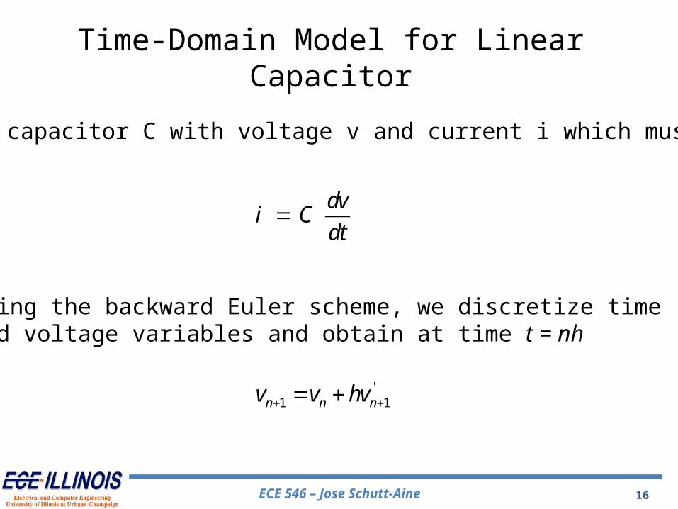
dv
i Cdt
For linear capacitor C with voltage v and current i which must satisfy
Using the backward Euler scheme, we discretize time and voltage variables and obtain at time t = nh
'1 1n n nv v hv
Time-Domain Model for Linear Capacitor

ECE 546 – Jose Schutt-Aine 1717
11' n
n
iv
C
11 n
n n
iv v h
C
1 1 - n n n
C Ci v v
h h
After substitution, we obtain
so that
The solution for the current at tn+1 is, therefore,
Time-Domain Model for Linear Capacitor

ECE 546 – Jose Schutt-Aine 18
i
v C
Backward Euler companion model at t=nh Trapezoidal companion model at t=nh
Time-Domain Model for Linear Capacitor
ECE 546 – Jose Schutt-Aine 19
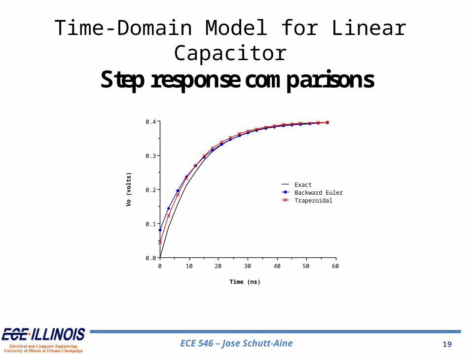
S te p r e s p o n s e c o m p a r is o n s
0 10 20 30 40 50 600.0
0.1
0.2
0.3
0.4
ExactBackward EulerTrapez oidal
Time (ns)
Vo (vo
lts)
Time-Domain Model for Linear Capacitor
ECE 546 – Jose Schutt-Aine 20
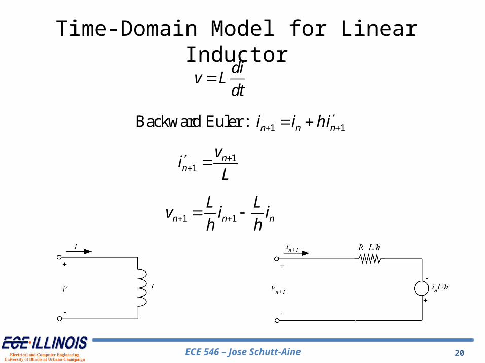
div L
dt
1 1Backward Euler : n n ni i hi
11
nn
vi
L
1 1n n n
L Lv i i
h h
Time-Domain Model for Linear Inductor
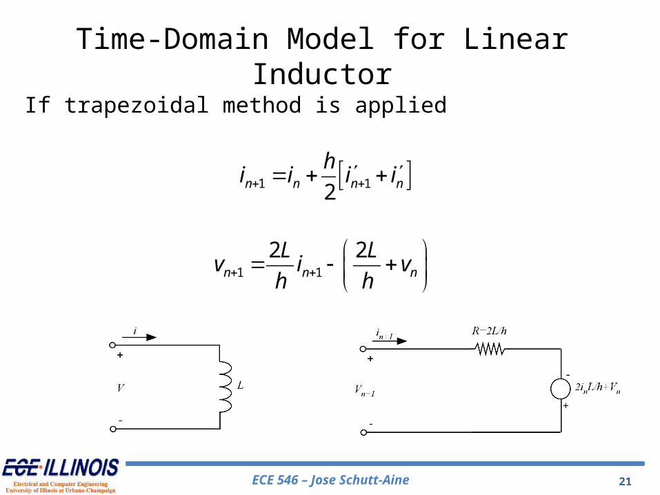
ECE 546 – Jose Schutt-Aine 21
1 12n n n n
hi i i i
1 1
2 2n n n
L Lv i v
h h
If trapezoidal method is applied
Time-Domain Model for Linear Inductor

ECE 546 – Jose Schutt-Aine 22
• Diode Properties– Two-terminal device that conducts current freely in one direction but blocks
current flow in the opposite direction.– The two electrodes are the anode which must be connected to a positive voltage
with respect to the other terminal, the cathode in order for current to flow.
+
-
V
I
The Diode
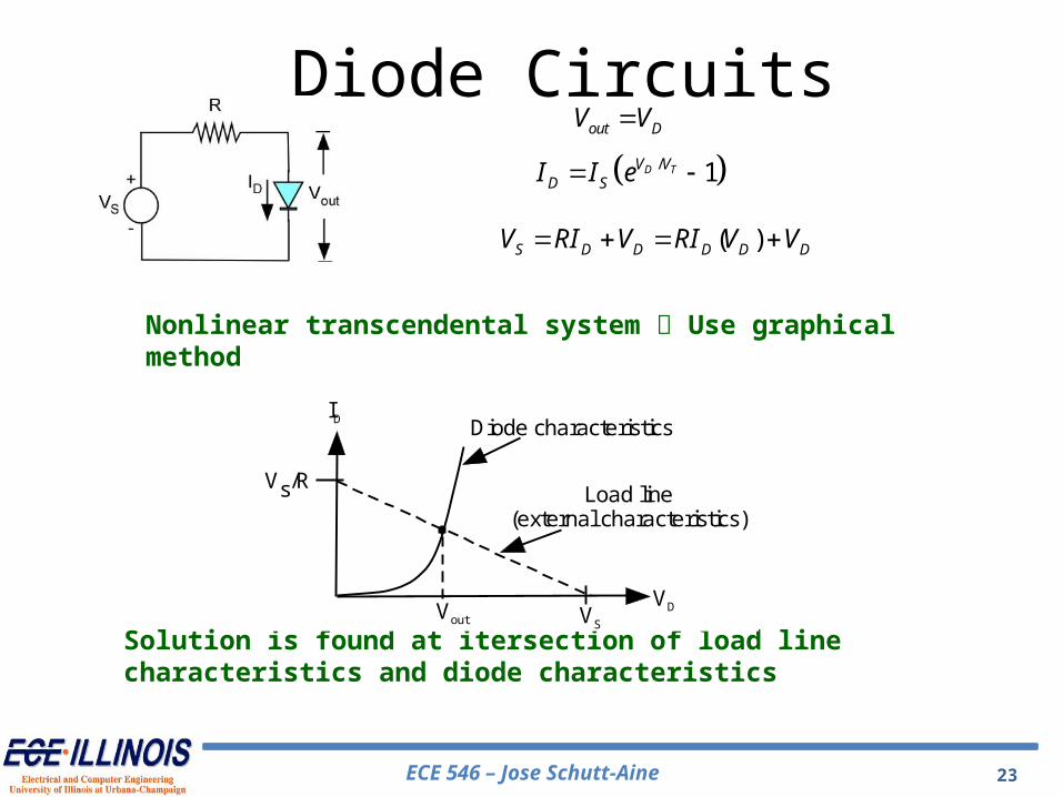
ECE 546 – Jose Schutt-Aine 23
out DV V
/ 1D TV VD SI I e
( )S D D D D DV RI V RI V V
Nonlinear transcendental system Use graphical method
Vs/R
VD
ID
VSVout
Load line(external characteristics)
Diode characteristics
Solution is found at itersection of load line characteristics and diode characteristics
Diode Circuits
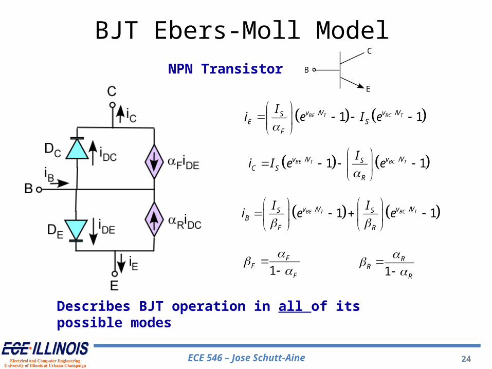
ECE 546 – Jose Schutt-Aine 24
NPN Transistor
// 1 1BC TBE T v Vv V SC S
R
Ii I e e
// 1 1BC TBE T v Vv VSE S
F
Ii e I e
// 1 1BC TBE T v Vv VS SB
F R
I Ii e e
1F
FF
1
RR
R
Describes BJT operation in all of its possible modes
24
B
C
E
BJT Ebers-Moll Model

ECE 546 – Jose Schutt-Aine 25
Problem: Wish to solve for f(x)=0
Use fixed point iteration method:
( ) ( ) ( )Define F x x K x f x
1: ( ) ( ) ( )k k k k kx F x x K x f x
With Newton Raphson: 1
1( ) [ ( )]df
K x f xdx
therefore, 11: [ ( )] ( )k k k kx x f x f x
Newton Raphson Method

ECE 546 – Jose Schutt-Aine 26
Newton Raphson Method(Graphical Interpretation)

ECE 546 – Jose Schutt-Aine 27
11: k k k kN R x x A f x
1 ( ) .k k k k k kA x A x f x S
xk+1 is the solution of a linear system of equations.
LU factk kA x S
Forward and backward substitution.
Ak is the nodal matrix for Nk
Sk is the rhs source vector for Nk.
Newton Raphson Algorithm
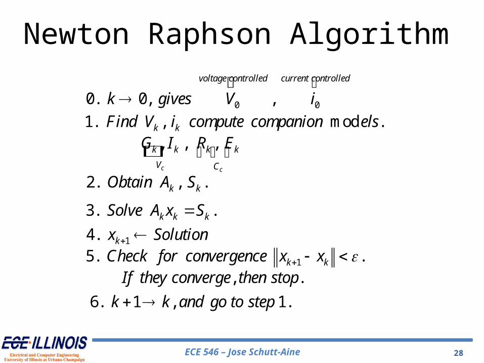
ECE 546 – Jose Schutt-Aine 28
0 00. 0, ,
voltage controlled current controlled
k gives V i1. , mod .k kFind V i compute companion els
, , ,c c
k k k k
V C
G I R E
2. , .k kObtain A S
3. .k k kSolve A x S
14. kx Solution
15. .k kCheck for convergence x x , .If they converge then stop
6. 1 , 1.k k and go to step
Newton Raphson Algorithm

ECE 546 – Jose Schutt-Aine 29
It is obvious from the circuit that the solution must satisfy f(V) = 0 We also have
/1'( ) tV Vs
t
If V e
R V
The Newton method relates the solution at the (k+1)th step to the solution at the kth step by
1
( ) -
'( )k
k kk
f VV V
f V
/ 1
1/
-1
V Vk t
k t
kes
k kV Vs
t
V EI
RV VI
eR V
Newton Raphson - Diode

ECE 546 – Jose Schutt-Aine 30
After manipulation we obtain
1
1 -k k k
Eg V J
R R
/ k tV Vsk
t
Ig e
V
/ ( -1) -k tV Vk s k kJ I e V g
Newton Raphson

ECE 546 – Jose Schutt-Aine 31
out DV V
/( ) 1 0D TV VD SD S
V Vf V I e
R
Newton-Raphson Method
Procedure is repeated until convergence to final (true) value of VD which is the solution. Rate of convergence is quadratic.
1( 1) ( ) ( ) ( )'( ) ( )k k k kx x f x f x
/1'( ) D TV VS
DT
If V e
R V
( )
( )
( )/
( 1) ( )
/
1
1
kTD D
kTD
kV VS
Sk k
D DV VS
T
V VI e
RV VI
eR V
Where is the value of VD at the kth iteration( )kDV
1
1 '( ) ( )k k k kx x f x f x
Use:
Diode Circuit – Iterative Method

ECE 546 – Jose Schutt-Aine 32
Newton-Raphson representation of diode circuit at kth iteration
/k tV Vsk
t
Ig e
V
/ ( -1) - Vk Vtk s k kJ I e V g
Newton Raphson for Diode
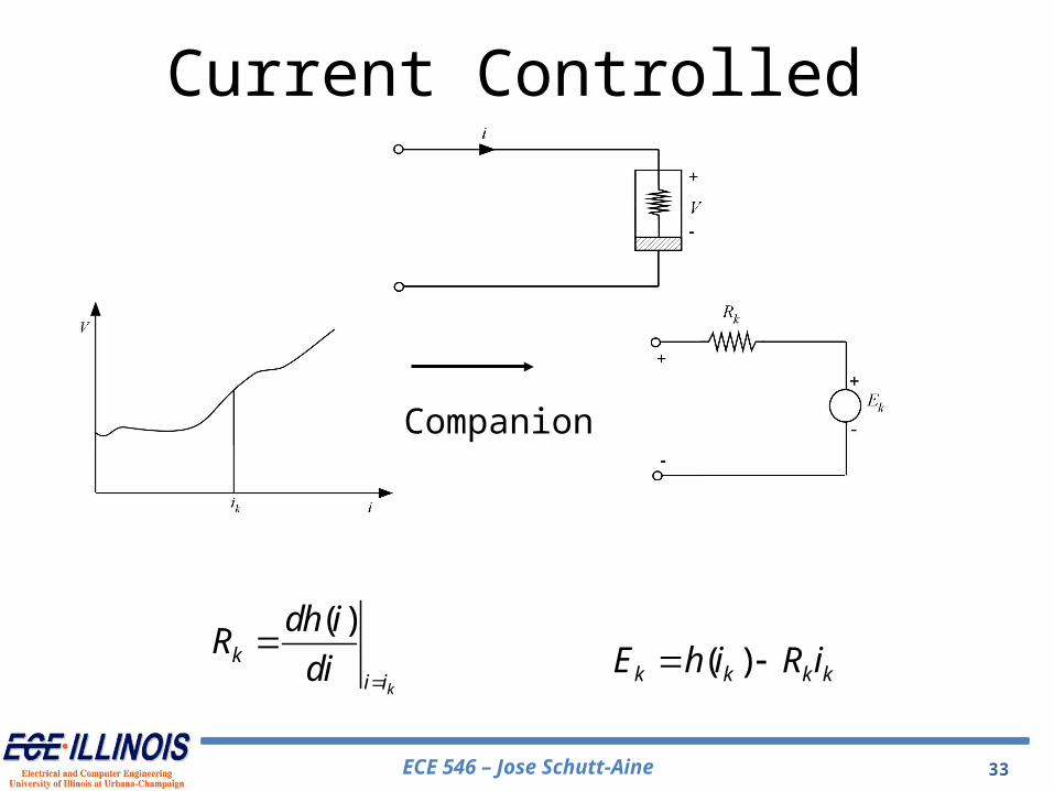
ECE 546 – Jose Schutt-Aine 33
Companion
( )
k
ki i
dh iR
di
( )k k k kE h i R i
Current Controlled
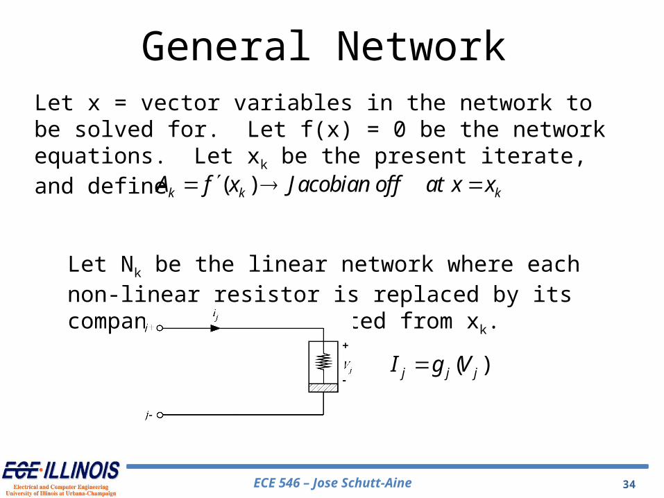
ECE 546 – Jose Schutt-Aine 34
Let x = vector variables in the network to be solved for. Let f(x) = 0 be the network equations. Let xk be the present iterate, and define
Let Nk be the linear network where each non-linear resistor is replaced by its companion model computed from xk.
( )k k kA f x Jacobian of f at x x
( )j j jI g V
General Network

ECE 546 – Jose Schutt-Aine 35
jk j k j kV P P
( )
k
kV V
dg VG
dV
k k k kI g V G V
Companionmodel
General Network
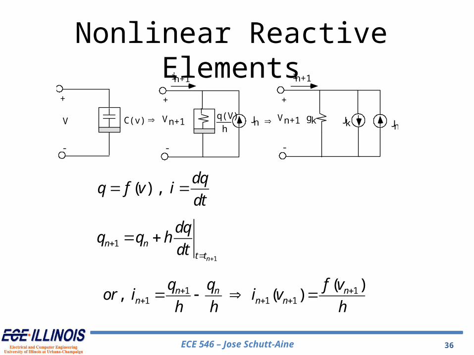
ECE 546 – Jose Schutt-Aine 36
C(v ) Jk Jngk
+
-
V Vn + 1
+
-
in + 1in + 1
Vn + 1
+
-
q (V)
hJn
( ) , dq
q f v idt
1
1
n
n nt t
dqq q h
dt
1 11 1 1
( ), ( )n n n
n n n
q q f vor i i v
h h h
Nonlinear Reactive Elements
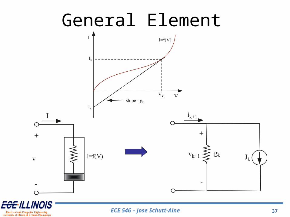
ECE 546 – Jose Schutt-Aine 37
General Element


