12
Embracing RSS Prepared by Mani Khaghani May 18, 2016

Embracing RSS
Prepared by Mani Khaghani
M a y 1 8 , 2 0 1 6
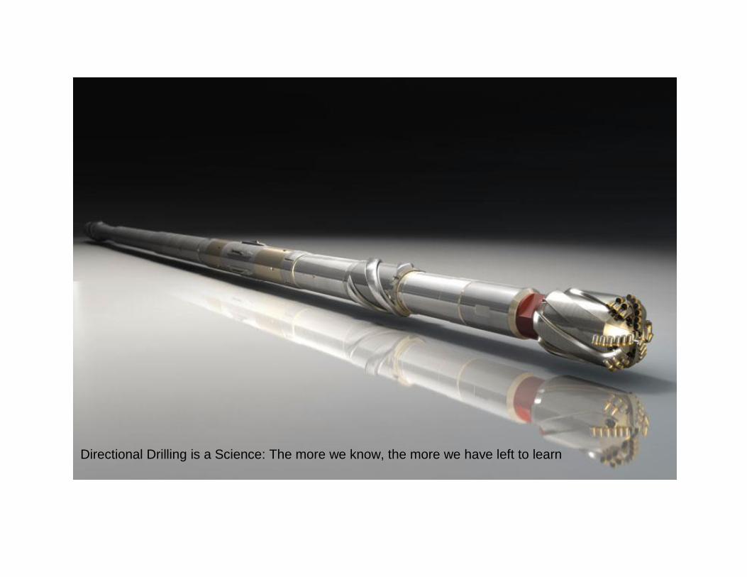
Directional Drilling is a Science: The more we know, the more we have left to learn

Preface
There is no doubt that the drilling industry has been through tremendous
changes over the past few years. Major directional drilling companies are
using sophisticated technologies to reduce costs while providing better
quality for their clients in the challenging market of the present. However, in
order for smaller companies to be successful in this environment, it is
necessary for them to adopt new and expensive technologies in order to
better meet the needs of their clients.
The key to success is through enhancing drilling efficiency, by reducing
NPT at the same time. Drilling efficiency is a term frequently used in the
drilling industry; however its value is frequently underestimated. Drilling
efficiency requires a higher degree of accuracy in the placement of
boreholes, while improving overall rates of penetration. In addition, a high
level of drilling efficiency will reduce the total cost of drilling while providing
improved directional control, drill further, eliminate sliding, provide better
hole cleaning and smoother boreholes, present fewer chances of sticking,
improve logging tool responses, and ease the running of casing. Rotary
Steerable Systems (RSS) were introduced to the oil and gas industry in the
early 1990’s in order to respond to requirements that are more complex
every year. These systems have the ability to drill faster, farther, and more
accurately than conventional steerable systems, fulfilling a high level of
drilling efficiency.
This paper will present an overview of Rotary Steerable Systems, the
benefits and best practices with RSS, and discuss well planning.

May 18, 2016
P a g e | 1
Overview
Rotary Steerable Systems consist of two basic types; “push-the-bit” and
“point-the-bit”. Pushing the bit refers to exerting lateral side force on the bit
as it drills ahead. Point-the-bit systems operate by placing a bend in the
system much like a standard motor assembly. This bend is held
geostationary with respect to the formation.
To understand the point-the-bit principle, one can make comparisons to
conventional drilling systems that use motors or turbines. A bent housing
and stabilizer on the bearing section allow the motor to drill in either an
oriented (sliding) or a rotary mode. In the rotary mode, both the bit and the
drill-string rotate. The rotation of the drill string negates the effect of the
bent housing, and the bit drills an over-gauge straight path parallel to the
axis of the drill string above the bent housing. In the sliding mode, only the
bit rotates. The motor changes the well course in the direction of the bent
housing, and the drill string slides down the hole behind the bit. In the point-
the-bit system, the ‘bent housing' is contained within the collar of the tool.
This ‘bent housing' is controlled by means of an electric motor which
rotates counter to the direction and at the same velocity as the drill string.
This control allows the ‘bent housing' to remain geo-stationary (non-
rotating) while the collar is rotating.
The Rotary Steering System introduces many advantages over
conventional steering systems which include:
- Eliminating time spent aligning the toolfaces; the rotary steerable tool
controls it automatically.
- Hole cleaning is improved as the pipe is rotated both while steering
the well and drilling straight. ECD will be kept consistent, rather than
fluctuating as the hole is loaded with cuttings while sliding and then
cuttings beds agitated and unloaded while rotating.
- Drag, which can cause shocks, vibration, and stick-slip is reduced
compared to sliding. This results in a more consistent weight-on-bit
and reduced stress on drilling equipment.

May 18, 2016
P a g e | 2
- There is less chance of the drillstring becoming stuck because of
continual movement.
- Hole quality using the extended gauge bits matched to the RRS is
much improved, with lower micro tortuosity, lower friction factors,
easier casing runs and large maximum collar pass through diameter.
- Deviation rates are more consistent as there is no change in mode
between steering and not steering to produce the required rate.
- Hire string rpm can be used, as there is no bend in the mud motor to
limit rpm.
- Wellbore profiles are generally smoother, with no transition ledges
resulting from changes between rotating and sliding modes
- Increased and improved quality of LWD data due to continuous
rotation.
- Higher ROP due to absence of need to slide
- Longer reach with lower drag due to rotation
May 18, 2016
P a g e | 3
Best practices
The best practices for the rotary steering system include tripping in, drilling
plugs, drilling the shoe, and rathole to gauge hole transition.
Tripping in
Tripping in should carried out with RIH filling the drill pipe as per normal
API standards and/or customer requirements to 30m above the planned
TOC (Top of Cement). Before establishing circulation, it is necessary to
break in RSS rotary seals to ensure the lubrication. After the seals have
been broken in, mud circulation should be slowly established to prevent
hydraulic shock and gradually increase flow rate to optimum circulation
rate.
The tool must be set in the “Zero” deflection position. The rotary torque
should be recorded because this is likely to be the cleanest the casing will
be regarding cutting accumulation and off bottom torque. A wash down
should be carried out once the full circulating parameters have been
established.
Close time monitoring of the RSS deflection should be carried out while
drilling cement, casing shoes and landing collars, and supervision of drilling
operations must focus on avoiding the chance of tool deflection being set
manually.
If the tool does take a deflection setting, the string should be immediately
removed off bottom and the tool must be reset to zero deflection with
confirmation in shaft.
Drilling Plugs
Parameters must be established and the last stand down must be washed
at full flow or as close to near full flow as possible. Tag cement and plugs
afterwards, and drill the cement away until reaching the plugs. Confirm
location by checking for sudden reductions in ROP and smooth torque.

May 18, 2016
P a g e | 4
When having problems drilling plugs with a conventional rock bit and rotary
BHA, one option often cited is to reduce flow rate to “heat up” and to spud
the bit to break up the plugs. However, reduced flow rate is not an option
with a PDC bit. It is essential that a PDC is kept cool, and Spudding is not
an acceptable practice. It is essential to utilize high flow rate, low bit weight,
low string RPM and patience.
It is easy to spin the plugs with a PDC bit since it is a drag bit that cuts in
shear. Even “non-rotating” plugs can spin especially the top plug. Some
spinning is unavoidable, even desirable since the heat build-up from friction
can help to weaken the rubber but avoid long periods on bottom with low
steady torque. It is usually the first light contact with the rubber that cuts the
most effectively. This is often seen as an increase in torque when tagging
the plug. It is this feature that should be exploited. Pick up frequently and
return to tag bottom gently. Note any increase in torque and take this as an
indication of how the bit is engaging the plugs.
Due to their parabolic profile, some PDC bits will core out the centre of a
plug, leaving the wiper rings intact. This in combination with a small junk
slot area can cause the bit to “piston” off bottom. The wiper ring forms a
seal round the bit and the effect is the same as packing off. String weight
decreases while bit weight and pump pressure increase. This can occur
repeatedly as each wiper ring is detached. The natural reaction is to cut
back the strokes and pick up off bottom to try to clear the bit. In most cases
it is more effective to stay on bottom and let the increased pressure blow
the ring past the bit. Watching the weight indicator and pressure gauge
swing up and down can be alarming but it is necessary to persist as long as
nothing else is at risk.
It is important to watch for packing off. All pressure increases are to be
treated as suspect and action must be taken to minimize potential damage.
Momentary pressure spikes do occur, but they are tolerable as long as they
clear quickly. The most likely pack off when using long gauge bits is around
the bit, but if a sustained pack-off occurs with tool seals, it is important to
consider taking a cautious approach.

May 18, 2016
P a g e | 5
Drilling the Shoe
The interface between the plugs and the float is a critical area, and
extremely important in establishing drilling efficiency. he bit is relatively
safe when sitting on rubber, but the float is a composite of hard cement,
plastic and aluminium with a hole in the middle. The profile of the bit does
not match the top of the float, and so must be drilled into the cement
carefully until all the cutters are in contact with the float. It is possible for
the center of the bit to be unsupported even at this point if there is mud
below the plugs, but procedure is the same as drilling a new bit into hard
formation.
Initially, only a few cutters are in contact and the watercourses are not yet
directing the flow properly. Excessive Weight-On-Bit (WOB) at this point
will damage the cutters since contact with cement will cause higher friction,
causing heat damages to PDC cutters. A similar scenario can occur if the
plugs are landed on a separate landing ring. Then only the gauge cutters
will be in contact till the ring is drilled out.
Case must be taken when breaking through the float. There may be an
empty pocket with no cement directly below the float. The bit will drill out
the center and will be supported only on the gauge cutters. WOB should be
reduced during breakthrough to prevent overloading the gauge cutters.
The same goes for drilling the shoe.
Newer aluminium reaming shoes drill easily enough, if a little slowly. Care
must be taken to avoid “trepan” the shoe, especially with a flat profile PDC,
which involves cutting out behind the nose leaving an uncut disc of
aluminium to be pushed to bottom.
Rat-hole to Gauge Hole Transition
The rat-hole is a repository for debris and cuttings. The reduction in AV as
fluid from the smaller section below enters the larger rathole means
cuttings tend to ’fall out’ on the low side in the rathole while drilling ahead.
As each BHA component passes through the rathole on trips in and out of
the hole it has the capability to disturb these cuttings and lift them in to the

May 18, 2016
P a g e | 6
flow stream. There is once again the potential for packing off in the reduced
ID of the casing if the pumps are bought up too fast.
String RPM must be kept to a minimum while back-reaming or rotating off
bottom in the rathole. High rotary speeds off bottom have a tendency to
generate BHA Whirl and / or lateral shocks as the BHA is not in
compression or braced against the borehole wall as is the situation while
drilling.
Vigilance is important when Reference Stabilizer and other stabilizers in the
BHA transition from the rat-hole to new in-gauge hole. This change in BHA
/ borehole geometry is a potential risk area regarding torque and pack- off
situations. In the event that a Leak Off Test or Formation Integrity Test is
required after drilling 3m of the new hole, then care should be taken when
pulling back into the shoe and resuming drilling after running back to
bottom.

May 18, 2016
P a g e | 7
Well planning
It is vitally important to establish responsibility among everyone at the site.
Everyone must understand what is happening downhole at all times, not
just the directional driller. With more information on hand and more planning
done, the chances of success are even better. Many factors are involved in
RSS well planning, but the most important ones are as follows:
Depth in/ out (MD&TVD): Accurate depths and lengths must be
established for optimal tool deployment and tool setup. For example, the
length of the section drilled is required to calculate how many tools are to
be deployed. The TVD is used to calculate hydrostatic pressure, so that the
correct set up of the tools DLS can be established. Everyone must know
which sections are build, drop or turn, etc.
Maximum dog leg to pass through: Past operation data should be
checked to determine at what point tool damage occurs due to overly high
dog legs. It is required to have the most accurate information available on
the formation. An investigation should be carried out on whether the quoted
pass through dog leg is realistic, due to dog legs being frequently higher
than planned.
Bottom hole temperature: It is important to check where the formation
information has come from.
Rotary table maximum RPM: It is necessary to establish the maximum
and minimum rotary table speeds that can be achieved without changing
gear. This information is used to set up the telemetry system of the tool.
Typical Slide - Rotation ratio: Need to know the typical percentage of
time which is spent sliding versus rotating. If little time is typically spent
sliding and the objective of the run is to improve ROP, then it may be
necessary to consider alternative wells.
Hole size for run: Preference should be for run in hole through a larger
gauge of hole to avoid reaming to bottom.

May 18, 2016
P a g e | 8
Typical bit issues: The performance of the tool is very sensitive to
changes in hole gauge. Everyone on site must be aware if holes are prone
to being washed out or if the bits are pinched out. Moreover, everyone
must know what types of bit are used to drill sections in offset wells to
assist with bit recommendations.
Conclusion
While this technology has been around for over twenty years, it has
acquired something of a negative reputation because this tool has an
extremely small margin for error, sometimes equal to zero. Other systems
have higher tolerances for deviation in dogleg severity in comparison to the
RSS. This technology has higher acquisition costs in comparison to
conventional steering systems, and inadequate pre-planning can result in
higher losses than with conventional steering systems.
In order for the system to accomplish higher drilling efficiency and to
reduce overall costs, it is absolutely necessary to have the most accurate
information available and a very high level of competency and
professionalism in the team. These are difficult requirements to meet, but
drilling companies that cannot increase their drilling efficiency will
eventually find that they have no clients, due to the competitiveness of the
market. The question is not whether RSS is right for their operations; rather
it is whether the company can operate at a high enough level to proficiently
utilize the technology.

May 18, 2016
P a g e | 9
References
Sperry Drilling Services: Geo-Pilot Manual
Weatherford: Revolution™ Rotary Steerable Operations


