64
Self-priming Pump Etaprime L Installation/Operating Manual Order number:

Self-priming Pump
Etaprime L
Installation/OperatingManual
Order number:

Installation/Operating Manual Etaprime LOriginal operating manual KSB Aktiengesellschaft All rights reserved. Contents provided herein must neither be distributed, copied, reproduced,processed for any other purpose, nor otherwise transmitted to a third party without KSB´s expresswritten consent. Subject to technical modification without prior notice. © KSB Aktiengesellschaft Frankenthal 01.02.2010

Contents
Glossary ................................................................................................ 5
1 General ................................................................................................ 6
1.1 Principles .......................................................................................................... 6
1.2 Installation of partly completed machinery .................................................. 6
1.3 Target group ................................................................................................... 6
1.4 Other applicable documents .......................................................................... 6
1.5 Symbols ............................................................................................................ 6
2 Safety ................................................................................................... 8
2.1 Key to safety symbols/markings ..................................................................... 8
2.2 General ............................................................................................................ 8
2.3 Intended use .................................................................................................... 8
2.4 Personnel qualification and training ............................................................. 9
2.5 Consequences and risks caused by non-compliance with these operatinginstructions ...................................................................................................... 9
2.6 Safety awareness ............................................................................................. 9
2.7 Safety information for the operator/user .................................................... 10
2.8 Safety information for maintenance, inspection and installation work ... 10
2.9 Unauthorised modes of operation ............................................................... 10
2.10 Explosion protection ..................................................................................... 10
3 Transport/Temporary Storage/Disposal ........................................... 13
3.1 Transport ....................................................................................................... 13
3.2 Storage and preservation ............................................................................. 14
3.3 Return to supplier ......................................................................................... 14
3.4 Disposal .......................................................................................................... 14
4 Description of the Pump (Set) .......................................................... 16
4.1 General description ....................................................................................... 16
4.2 Designation ................................................................................................... 16
4.3 Name plate .................................................................................................... 16
4.4 Design details ................................................................................................ 16
4.5 Design and function ...................................................................................... 17
4.6 Noise characteristics ..................................................................................... 18
4.7 Scope of supply ............................................................................................. 18
4.8 Dimensions and weights ............................................................................... 18
5 Installation at Site ............................................................................. 19
5.1 Safety regulations ......................................................................................... 19
5.2 Checking the site before installation ........................................................... 19
5.3 Installing the pump set ................................................................................. 19
5.4 Piping ............................................................................................................. 21
Contents
Etaprime L 3 of 64

5.5 Protective equipment ................................................................................... 23
5.6 Checking the coupling alignment ................................................................ 24
5.7 Aligning the pump and motor ..................................................................... 25
5.8 Electrical connection ..................................................................................... 26
5.9 Checking the direction of rotation .............................................................. 28
6 Commissioning/Start-up/Shutdown ................................................. 29
6.1 Commissioning/start-up ................................................................................ 29
6.2 Operating limits ............................................................................................ 34
6.3 Shutdown/storage/preservation ................................................................... 36
6.4 Returning to service after storage ............................................................... 36
7 Servicing/Maintenance ...................................................................... 38
7.1 Safety regulations ......................................................................................... 38
7.2 Servicing/inspection ...................................................................................... 39
7.3 Drainage/disposal .......................................................................................... 43
7.4 Dismantling the pump set ............................................................................ 44
7.5 Reassembling the pump set .......................................................................... 46
7.6 Tightening torques ....................................................................................... 50
7.7 Spare parts stock ........................................................................................... 52
8 Trouble-shooting ............................................................................... 54
9 Related Documents ........................................................................... 56
9.1 Sectional Drawing and List of Components ............................................... 56
10 EC Declaration of Conformity ......................................................... 60
11 Certificate of Decontamination ....................................................... 61
Index .................................................................................................. 62
Contents
4 of 64 Etaprime L

Glossary
Back pull-out designThe complete back pull-out unit can be pulledout without having to remove the pump casingfrom the piping.
Back pull-out unitPump without pump casing; partly completedmachinery
Certificate of decontaminationA certificate of decontamination certifies thatthe pump (set) has been properly drained toeliminate any environmental and healthhazards arising from components in contactwith the fluid handled.
Discharge lineThe line which is connected to the dischargenozzle
Hydraulic systemThe part of the pump in which the kineticenergy is converted into pressure energy
Pool of pumpsPumps which are purchased and storedindependently of their later use
PumpMachine without drive, additional componentsor accessories
Pump setComplete pump set consisting of pump, drive,additional components and accessories
Self-priming abilityAbility of a filled pump to evacuate a suctionline, i.e. to self-prime from an unfilled suctionline.
Suction lift line/suction head lineThe line which is connected to the suctionnozzle
Glossary
Etaprime L 5 of 64

1 General
1.1 Principles
This manual is supplied as an integral part of the type series and variants indicatedon the front cover. This manual describes the proper and safe use of this equipmentin all phases of operation.
The name plate indicates the type series and size, the main operating data, the ordernumber and the order item number. The order number and order item number clearly identify the pump (set) and serve as identification for all further businessprocesses.
In the event of damage, immediately contact your nearest KSB Service centre tomaintain the right to claim under warranty.
Noise characteristics (⇨ Section 4.6 Page 18)
1.2 Installation of partly completed machinery
To install partly completed machinery supplied by KSB, please refer to the sub-sections under Servicing/Maintenance. (⇨ Section 7.5.5 Page 49)
1.3 Target group
This manual is aimed at the target group of trained and qualified specialist technicalpersonnel. (⇨ Section 2.4 Page 9)
1.4 Other applicable documents
Table 1: Overview of other applicable documents
Document ContentsData sheet Description of the technical data of the pump
(set)General arrangement drawing/Outline drawing
Description of mating and installation dimensionsfor the pump (set)
Drawing of auxiliary connections Description of auxiliary connectionsHydraulic characteristic curve Characteristic curves showing head, NPSH
required, efficiency and power inputGeneral assembly drawing1) Sectional drawing of the pump
Sub-supplier product literature1) Operating manuals and other product literatureof accessories and integrated machinerycomponents
Spare parts lists1) Description of spare parts
Piping layout1) Description of auxiliary piping
List of components1) Description of all pump components
1.5 Symbols
Table 2: Symbols used in this manual
Symbol Description✓ Conditions which need to be fulfilled before proceeding with the
step-by-step instructions⊳ Safety instructions⇨ Result of an action⇨ Cross-references
1) If agreed to be included in the scope of supply
1 General
6 of 64 Etaprime L

Symbol Description1.
2.
Step-by-step instructions
NoteRecommendations and important information on how to handlethe product
1 General
Etaprime L 7 of 64

2 SafetyAll the information contained in this section refers to hazardous situations.
2.1 Key to safety symbols/markings
Table 3: Definition of safety symbols/markings
Symbol Description
! DANGER DANGERThis signal word indicates a high-risk hazard which, if not avoided,will result in death or serious injury.
! WARNING WARNINGThis signal word indicates a medium-risk hazard which, if notavoided, could result in death or serious injury.
CAUTION CAUTIONThis signal word indicates a hazard which, if not avoided, couldresult in damage to the machine and its functions.Explosion protectionThis symbol identifies information about avoiding explosions inpotentially explosive atmospheres in accordance with EC Directive94/9/EC (ATEX).General hazardIn conjunction with one of the signal words this symbol indicates ahazard which will or could result in death or serious injury.
Electrical hazardIn conjunction with one of the signal words this symbol indicates ahazard involving electrical voltage and identifies informationabout protection against electrical voltage.Machine damage In conjunction with the signal word CAUTION this symbol indicatesa hazard for the machine and its functions.
2.2 General
This manual contains general installation, operating and maintenance instructionsthat must be observed to ensure safe pump operation and prevent personal injuryand damage to property.
The safety information in all sections of this manual must be complied with.
This manual must be read and completely understood by the responsible specialistpersonnel/operators prior to installation and commissioning.
The contents of this manual must be available to the specialist personnel at the siteat all times.
Information attached directly to the pump must always be complied with and bekept in a perfectly legible condition at all times. This applies to, for example:
▪ Arrow indicating the direction of rotation
▪ Markings for connections
▪ Name plate
The operator is responsible for ensuring compliance with all local regulations whichare not taken into account in this manual.
2.3 Intended use
The pump (set) must only be operated within the operating limits which aredescribed in the other applicable documents.
▪ Only operate pumps/pump sets which are in perfect technical condition.
▪ Do not operate partially assembled pumps/pump sets.
! DANGER
2 Safety
8 of 64 Etaprime L

▪ Only use the pump to handle the fluids specified in the data sheet or productliterature of the respective design variant.
▪ Never operate the pump without the fluid to be handled.
▪ Observe the minimum flow rates indicated in the data sheet or product literature(to prevent overheating, bearing damage, etc).
▪ Observe the maximum flow rates indicated in the data sheet or productliterature (to prevent overheating, mechanical seal damage, cavitation damage,bearing damage, etc).
▪ Do not throttle the flow rate on the suction side of the pump (to preventcavitation damage).
▪ Consult the manufacturer about any use or mode of operation not described inthe data sheet or product literature.
Prevention of foreseeable misuse
▪ Never open discharge-side shut-off elements further than permitted.
– The maximum flow rate specified in the data sheet or product literaturewould be exceeded.
– Risk of cavitation damage
▪ Never exceed the permissible operating limits specified in the data sheet orproduct literature regarding pressure, temperature, etc.
▪ Observe all safety information and instructions in this manual.
2.4 Personnel qualification and training
All personnel involved must be fully qualified to install, operate, maintain andinspect the machinery this manual refers to.
The responsibilities, competence and supervision of all personnel involved ininstallation, operation, maintenance and inspection must be clearly defined by theoperator.
Deficits in knowledge must be rectified by sufficiently trained specialist personneltraining and instructing the personnel who will carry out the respective tasks. Ifrequired, the operator can commission the manufacturer/supplier to train thepersonnel.
Training on the pump (set) must always be supervised by technical specialistpersonnel.
2.5 Consequences and risks caused by non-compliance with these operatinginstructions
▪ Non-compliance with these operating instructions will lead to forfeiture ofwarranty cover and of any and all rights to claims for damages.
▪ Non-compliance can, for example, have the following consequences:
– Hazards to persons due to electrical, thermal, mechanical and chemicaleffects and explosions
– Failure of important product functions
– Failure of prescribed maintenance and servicing practices
– Hazard to the environment due to leakage of hazardous substances
2.6 Safety awareness
In addition to the safety information contained in this manual and the intended use,the following safety regulations shall be complied with:
▪ Accident prevention, health and safety regulations
▪ Explosion protection regulations
2 Safety
Etaprime L 9 of 64

▪ Safety regulations for handling hazardous substances
▪ Applicable standards and laws
2.7 Safety information for the operator/user
▪ The operator shall fit contact guards for hot, cold or moving parts and check thatthe guards function properly.
▪ Do not remove the contact guard while the pump is running.
▪ Connect an earth conductor to the metal jacket if the fluid handled iselectrostatically charged.
▪ Provide the personnel with protective equipment and make sure it is used.
▪ Contain leakages (e.g at the shaft seal) of hazardous fluids handled (e.g.explosive, toxic, hot) so as to avoid any danger to persons and the environment.Adhere to all relevant laws.
▪ Eliminate all electrical hazards. (In this respect refer to the applicable nationalsafety regulations and/or regulations issued by the local energy supplycompanies.)
2.8 Safety information for maintenance, inspection and installation work
▪ Modifications or alterations of the pump are only permitted with themanufacturer's prior consent.
▪ Use only original spare parts or parts authorised by the manufacturer. The use ofother parts can invalidate any liability of the manufacturer for consequentialdamage.
▪ The operator ensures that all maintenance, inspection and installation work isperformed by authorised, qualified specialist personnel who are thoroughlyfamiliar with the manual.
▪ Carry out work on the pump (set) during standstill only.
▪ The pump casing must have cooled down to ambient temperature.
▪ Pump pressure must have been released and the pump must have been drained.
▪ When taking the pump set out of service always adhere to the proceduredescribed in the manual. (⇨ Section 6.1.7 Page 33)
▪ Decontaminate pumps which handle fluids posing a health hazard. (⇨ Section 7.3Page 43)
▪ As soon as the work is completed, re-install and/or re-activate any safety-relevantand protective devices. Before returning the product to service, observe allinstructions on commissioning. (⇨ Section 6.1 Page 29)
2.9 Unauthorised modes of operation
Never operate the pump (set) outside the limits stated in the data sheet and in thismanual.
The warranty relating to the operating reliability and safety of the supplied pump(set) is only valid if the equipment is used in accordance with its intended use. (⇨Section 2.3 Page 8)
2.10 Explosion protection
Always observe the information on explosion protection given in this section whenoperating the pump in potentially explosive atmospheres.
! DANGER
2 Safety
10 of 64 Etaprime L

Only pumps/pump sets marked as explosion-proof and identified as such in the datasheet may be used in potentially explosive atmospheres.
Special conditions apply to the operation of explosion-proof pump sets to ECDirective 94/9/EC (ATEX). Especially adhere to the sections in this manual marked with the Ex symbol and thefollowing sections (⇨ Section 2.10.1 Page 11) to (⇨ Section 2.10.4 Page 12). The explosion-proof status of the pump set is only assured if the pump set is used inaccordance with its intended use. Never operate the pump (set) outside the limits stated in the data sheet and on thename plate.Prevent impermissible modes of operation at all times.
2.10.1 Marking
The marking on the pump refers to the pump only. Example of such marking: II 2 G c TX Refer to the Temperature limits table for the temperatures permitted for theindividual pump variants.
An EC manufacturer's declaration is required for the shaft coupling; the shaftcoupling must be marked accordingly.
The motor must be considered separately.
2.10.2 Temperature limits
In normal pump operation, the highest temperatures are to be expected on thesurface of the pump casing and at the shaft seal. The surface temperature at the pump casing corresponds to the temperature of thefluid handled. If the pump is heated, the operator of the system is responsible forobserving the specified temperature classes and fluid temperature (operatingtemperature). The table below lists the temperature classes and the resulting theoreticaltemperature limits of the fluid handled. (A possible temperature rise in the shaft sealarea has already been taken into account).
The temperature class specifies the maximum permissible temperature at the surfaceof the pump set during operation. For the permissible operating temperature of thepump in question refer to the data sheet.
Table 4: Temperature limits
Temperature class as per EN 13463-1 Maximum permissible fluidtemperature
T1 Temperature limit of the pumpT2 280 ℃T3 185 ℃T4 120 ℃T5 85 ℃T6 Only after consultation
with the manufacturer
In the following cases, and if ambient temperatures are higher, contact themanufacturer.
Compliance with temperature class T5 is warranted for the area of the rollingelement bearings based on an ambient temperature of 40°C, assuming that thepump set is properly serviced and operated and that the surfaces in the bearing areaare freely exposed to the atmosphere.
If temperature class T6 has to be complied with, special measures may have to betaken with regard to the bearing temperatures.
Misuse, malfunctions or non-compliance with the instructions may result insubstantially higher temperatures.
Pump
Shaft coupling
Motor
Temperature class T5
Temperature class T6
2 Safety
Etaprime L 11 of 64

If the pump is to be operated at a higher temperature, the data sheet is missing or ifthe pump is part of a pool of pumps, contact KSB for the maximum permissibleoperating temperature.
If a pump is supplied without motor (as part of a pool of pumps), the motor specifiedin the pump data sheet must meet the following conditions:
▪ The permissible temperature limits on the motor flange and motor shaft must behigher than the temperatures generated by the pump.
▪ Contact the manufacturer for the actual pump temperatures.
2.10.3 Monitoring equipment
The pump (set) must only be operated within the limits specified in the data sheetand on the name plate. If the system operator cannot warrant compliance with these operating limits,appropriate monitoring devices must be used. Check whether monitoring equipment is required to ensure that the pump setfunctions properly.
Contact KSB for further information on monitoring equipment.
2.10.4 Operating limits
The minimum flows indicated in (⇨ Section 6.2.3 Page 35) refer to water and water-like fluids. Longer operating periods with these fluids and at the flow rates indicatedwill not cause an additional increase in the temperatures on the pump surface.However, if the physical properties of the fluids handled are different from water, itis essential to check whether an additional heat build-up may occur and if theminimum flow rate must therefore be increased. The calculation formula in (⇨Section 6.2.3 Page 35) can be used to check whether an additional heat build-upmay lead to a hazardous temperature increase at the pump surface.
Motor supplied by theoperator
2 Safety
12 of 64 Etaprime L

3 Transport/Temporary Storage/Disposal
3.1 Transport
DANGERThe pump (set) could slip out of the suspension arrangementDanger to life from falling parts!
▷ Always transport the pump (set) in horizontal position.
▷ Never attach the suspension arrangement to the free shaft end or the motoreyebolt.
▷ Refer to the weights given in the general arrangement drawing.
▷ Observe the local accident prevention regulations.
▷ Use suitable, permitted lifting tackle, e.g. self-tightening lifting tongs.
To transport the pump/pump set suspend it from the lifting tackles as follows.
Fig. 1: Transporting the pump
max. 90 °
Fig. 2: Transporting the complete pump set
max. 90 °
Fig. 3: Transporting the pump on baseplate
3 Transport/Temporary Storage/Disposal
Etaprime L 13 of 64

3.2 Storage and preservation
If commissioning is to take place some time after delivery, we recommend that thefollowing measures be taken for pump (set) storage.
CAUTIONDamage during storage by humidity, dirt, or verminCorrosion/contamination of the pump (set)!
▷ For outdoor storage cover the pump (set) or the packaged pump (set) andaccessories with waterproof material.
CAUTIONWet, contaminated or damaged openings and connectionsLeakage or damage to the pump set!
▷ Only remove caps/covers from the openings of the pump set at the time ofinstallation.
Store the pump (set) in a dry, protected room where the atmospheric humidity is asconstant as possible.
Rotate the shaft by hand once a month, e.g. via the motor fan.
If properly stored indoors, the pump set is protected for a maximum of 12 months.New pumps/pump sets are supplied by our factory duly prepared for storage.
For storing a pump (set) which has already been operated, observe the relevantinstructions. (⇨ Section 6.3.1 Page 36)
3.3 Return to supplier
1. Drain the pump as per operating instructions. (⇨ Section 7.3 Page 43)
2. Always flush and clean the pump, particularly if it has been used for handlingnoxious, explosive, hot or other hazardous fluids.
3. If the fluids handled by the pump leave residues which might lead to corrosiondamage when coming into contact with atmospheric humidity, or which mightignite when coming into contact with oxygen, the pump set must also beneutralised, and anhydrous inert gas must be blown through the pump fordrying purposes.
4. Always complete and enclose a certificate of decontamination when returningthe pump set. (⇨ Section 11 Page 61)It is imperative to indicate any safety and decontamination measures taken.
NOTEIf required, a blank certificate of decontamination can be downloaded from the KSB website at: www.ksb.com/certificate_of_decontamination
3.4 Disposal
WARNINGFluids posing a health hazardHazardous to persons and the environment!
▷ Collect and properly dispose of flushing liquid and any fluid residues.
▷ Wear safety clothing and a protective mask, if required.
▷ Observe all legal regulations on the disposal of fluids posing a health hazard.
1. Dismantle the pump (set).Collect greases and other lubricants during dismantling.
2. Separate and sort the pump materials, e.g. by:- Metals- Plastics
3 Transport/Temporary Storage/Disposal
14 of 64 Etaprime L

- Electronic waste- Greases and other lubricants
3. Dispose of materials in accordance with local regulations or in another controlledmanner.
3 Transport/Temporary Storage/Disposal
Etaprime L 15 of 64

4 Description of the Pump (Set)
4.1 General description
▪ Self-priming pump
The pump is designed for handling clean or contaminated fluids in waste watermanagement, on construction sites, in agriculture, in the general or chemicalindustry, in the petroleum, food processing and canning industry and for circulatingsolvents and cleaning agents with a viscosity of up to 50 mm²/s. A solids content of upto 3 % is permissible, but the fluid handled must not contain long fibres.
4.2 Designation
Example: Etaprime GL 80-200 GL10
Table 5: Key to the designation
Code DescriptionEtaprime Type seriesG Casing material, e.g. G = grey cast ironL Long-coupled design80 Nominal discharge nozzle diameter [mm], encoded200 Nominal impeller diameter [mm], encodedGL10 Seal code, e.g. GL10 = mechanical seal Q1Q1X4GG
4.3 Name plate
ETAPRIME GL 80-200 GL109971234567 000100 / 01Q 52 m3/h l H 34 m
1 mm2/sn 2900 1/min l 2008
AktiengesellschaftD-67227 Frankenthal
Id-No. 00 117 385 ZN 3804 - C 37 x 52
1
2
5
4
3
9
8
76
Fig. 4: Name plate
1 Type series, pump size and design 2 KSB order number(ten digits)
3 Flow rate 4 Speed5 Kinematic viscosity of the fluid
handled6 Order item number
(six digits)7 Consecutive number
(two digits)8 Head
9 Year of construction
4.4 Design details
Design
▪ Volute casing pump
▪ Back pull-out design (from size 40-140)
▪ Horizontal installation
▪ Self-priming
4 Description of the Pump (Set)
16 of 64 Etaprime L

▪ Single-stage
▪ Single-entry
Pump cas ing
▪ Radially split volute casing
▪ Volute casing with integrally cast pump feet (from pump size 40-140)
Impel ler type
▪ Open multi-vane impeller
Bearings
▪ Radial ball bearings
▪ Grease lubrication
▪ Oil lubrication
Shaft seal
▪ The shaft is fitted with a replaceable shaft sleeve in the shaft seal area (frompump size 40-140).
▪ Standardised mechanical seal to EN 12756
4.5 Design and function
51 2 3 4
6 7 8 9 10Fig. 5: Sectional drawing
1 Clearance gap 2 Discharge nozzle3 Casing cover 4 Shaft5 Bearing bracket 6 Suction nozzle7 Impeller 8 Shaft seal9 Rolling element bearing, pump end 10 Rolling element bearing, motor
end
The pump is designed with an axial fluid inlet and a radial outlet. The pump sectionruns in its own bearings and is connected to the motor by a shaft coupling.
The fluid enters the pump axially via a suction nozzle (6) and is accelerated by therotating impeller (7), which causes a cylindrical flow towards the outside of thepump. The flow profile of the pump casing converts the kinetic energy of the fluidinto pressure energy. The fluid is pumped to the discharge nozzle (2), where it leavesthe pump. The clearance gap (1) prevents any fluid from flowing back from thecasing into the inlet. The hydraulic system is closed with a casing cover (3) at the rear
Design
Function
4 Description of the Pump (Set)
Etaprime L 17 of 64

side of the impeller; the shaft (4) enters the casing via the casing cover (3). The shaftpassage through the casing cover is sealed towards the atmosphere with a shaft seal(8). The shaft runs in rolling element bearings (9 and 10), which are supported by abearing bracket (5) linked with the pump casing and/or casing cover. The filled pumpis self-priming.
The pump is sealed by a standardised mechanical seal.
4.6 Noise characteristics
Table 6: Surface sound pressure level LpA2) 3)
Size Pump set2900 rpm
[dB]
Size Pump set2900 rpm
[dB]25-100 71 65-180 7932-120 73 80-170 7940-110 73 80-190 8040-140 76 80-200 7950-130 76 100-240.1 8050-160 77 100-240 8165-150 78 125-260 84
4.7 Scope of supply
Depending on the model, the following items are included in the scope of supply:
▪ Pump
▪ Electric motor
▪ Flexible coupling with or without spacer
▪ Coupling guard to EN 294
DANGERRisk of ignition by frictional sparksRisk of explosion!
▷ Choose a coupling guard material that is non-sparking in the event ofmechanical contact (see DIN EN 13463-1).
▷ If any coupling parts are made of aluminium, a brass coupling guard must beused.
▪ Channel section steel or folded steel plate
Optional
▪ Cast baseplate (to ISO 3661)
▪ As required
4.8 Dimensions and weights
For dimensions and weights please refer to the general arrangement drawing/outlinedrawing of the pump (set).
Sealing
Drive
Shaft coupling
Contact guard
Baseplate
Special accessories
2) Spatial average; as per ISO 3744 and EN 12639; valid for pump operation in the Q/Qopt = 0.80 - 1.1 range and for non-cavitating operation. If noise levels are to be warranted: Add +3 dB for measuring and constructional tolerance.
3) Increase for 60 Hz operation: 3500 rpm +3 dB; 1750 rpm +1 dB
4 Description of the Pump (Set)
18 of 64 Etaprime L

5 Installation at Site
5.1 Safety regulations
DANGERImproper installation in potentially explosive atmospheresExplosion hazard!Damage to the pump set!
▷ Comply with the applicable local explosion protection regulations.
▷ Observe the information in the data sheet and on the name plates of pump andmotor.
5.2 Checking the site before installation
Place of instal lat ion
WARNINGInstallation on foundations which are unsecured and cannot support the loadPersonal injury and damage to property!
▷ Make sure the foundation concrete is of sufficient strength (min. X0 toDIN 1045).
▷ Only place the pump set on a foundation whose concrete has set firmly.
▷ Only place the pump set on a horizontal and level surface.
▷ Refer to the weights given in the general arrangement drawing.
1. Check the structural requirements. All structural work required must have been prepared in accordance with thedimensions stated in the outline drawing/general arrangement drawing.
5.3 Installing the pump set
Always install the pump set in horizontal position.
DANGERExcessive temperatures due to improper installationExplosion hazard!
▷ Install the pump in horizontal position to ensure self-venting of the pump.
5.3.1 Installation on the foundation
12
43Fig. 6: Fitting the shims
1 Bolt-to-bolt clearance 2 Shim3 Shim for bolt-to-bolt clearance >
800 mm4 Foundation bolt
✓ The foundation has the required strength and characteristics.
5 Installation at Site
Etaprime L 19 of 64

✓ The foundation has been prepared in accordance with the dimensions given inthe outline drawing / general arrangement drawing.
1. Position the pump set on the foundation and use a spirit level to align shaft anddischarge nozzle.Permissible deviation: 0.2 mm/m
2. If required, use shims (2) to adjust the height. Always fit shims immediately to the left and right of the foundation bolts (4)between the baseplate/foundation frame and the foundation itself.For a bolt-to-bolt clearance > 800 mm, fit additional shims (3) halfway betweenthe adjoining holes. All shims must lie perfectly flush.
3. Insert the foundation bolts (4) into the holes provided.
4. Use concrete to set the foundation bolts (4) into the foundation.
5. Wait until the concrete has set firmly, then align the baseplate.
6. Tighten the foundation bolts (4) evenly and firmly.
NOTEFor baseplates more than 400 mm wide it is recommended to grout the baseplate withlow-shrinkage concrete.
NOTEFor baseplates made of grey cast iron it is recommended to grout the baseplate with low-shrinkage concrete.
NOTEFor low-noise operation contact KSB to check whether the pump set can be installed onanti-vibration mounts.
5.3.2 Installation without foundation
4
1
2
3
Fig. 7: Levelling elements
1, 3 Locknut 2 Levelling nut4 Levelling element
✓ The installation surface has the required strength and characteristics.
1. Position the pump set on the levelling elements (4) and align it with the help of aspirit level (on the shaft/discharge nozzle).
2. To adjust any differences in height, loosen the bolts and locknuts (1, 3) of thelevelling elements (4).
3. Turn the levelling nut (2) until any differences in height have been compensated.
4. Re-tighten the locknuts (1, 3) at the levelling elements (4).
5 Installation at Site
20 of 64 Etaprime L

5.4 Piping
5.4.1 Connecting the piping
DANGERImpermissible loads acting on the pump nozzlesDanger to life from leakage of hot, toxic, corrosive or flammable fluids!
▷ Do not use the pump as an anchorage point for the piping.
▷ Anchor the pipelines in close proximity to the pump and connect them withouttransmitting any stresses or strains.
▷ Observe the permissible forces and moments at the pump nozzles. (⇨ Section5.4.2 Page 22)
▷ Take appropriate measures to compensate thermal expansion of the piping.
CAUTIONIncorrect earthing during welding work at the pipingDestruction of rolling element bearings (pitting effect)!
▷ Never earth the electric welding equipment on the pump or baseplate.
▷ Prevent current flowing through the rolling element bearings.
NOTEIt is recommended to install check and shut-off elements in the system, depending on thetype of plant and pump. However, such elements must not obstruct proper drainage orhinder disassembly of the pump.
CAUTIONWhen handling gaseous fluids or fluids which tend to froth, the pump will not be self-priming.Pump is running, but does not deliver!
▷ Install a check valve in the suction line.
✓ The suction lift lines/suction head lines have been laid with a rising/downwardslope towards the pump.
✓ The nominal diameters of the pipelines are at least equal to the nominaldiameters of the pump nozzles.
✓ To prevent excessive pressure losses, adapters to larger diameters have a diffuserangle of approx. 8°.
✓ The pipelines have been anchored in close proximity to the pump and connectedwithout transmitting any stresses or strains.
1. Before installing the pump in the piping, remove the flange covers on the suctionand discharge nozzles of the pump.
CAUTIONWelding beads, scale and other impurities in the pipingDamage to the pump!
▷ Free the piping from any impurities.
▷ If necessary, install a filter.
▷ Observe the instructions in (⇨ Section 7.2.2.3 Page 41).
5 Installation at Site
Etaprime L 21 of 64

0.5 to 1 m
H1geo
≤ 1 m
Fig. 8: Distances of suction and discharge lines
NOTEUse a filter with laid-in wire mesh (mesh width 0.5 mm, wire diameter 0.25 mm) ofcorrosion-resistant material.Use a filter three times the diameter of the piping.Conical filters have proved suitable.
2. Connect the pump nozzles to the piping.Observe the dimensions stated above (see illustration: Dimensions of suction anddischarge lines).
CAUTIONAggressive flushing and pickling agentsDamage to the pump!
▷ Match the cleaning operation mode and duration for flushing and picklingservice to the casing and seal materials used.
5.4.2 Permissible forces and moments at the pump nozzles
FV
FVmax
2FH
FHmax
2
Mtmax
Mt
2
+ + - 1
FV
FH
FH
FVFH
FH
Fig. 9: Forces and moments at the pump nozzles
The following condition must be met:
5 Installation at Site
22 of 64 Etaprime L

∑IFVI, ∑IFHI, and ∑IMtI are the sums of the absolute values of the respective loadsacting on the nozzles. Neither the load direction nor the load distribution among thenozzles are taken into account in these sums.
Table 7: Forces and moments at the pump nozzles
Pump size Etaprime GL Etaprime CLFVmax
[kN]
FHmax
[kN]
Mtmax
[kNm]
FVmax
[kN]
FHmax
[kN]
Mtmax
[kNm]25-100 2.5 1.7 0.5 - - -32-120 2.5 1.7 0.5 4.25 2.96 0.9540-110 2.6 1.8 0.6 4.25 2.96 0.9540-140 2.7 1.9 0.7 4.25 2.96 0.9550-130 2.7 2.0 0.75 4.53 3.05 1.2750-160 2.7 2.0 0.75 4.53 3.05 1.2765-150 3.0 2.2 0.85 5.04 3.47 1.3465-180 3.0 2.2 0.85 6.0 4.44 2.0880-170 3.5 2.8 1.2 6.5 5.0 2.580-190 4.0 2.9 1.45 - - -80-200 4.0 2.9 1.45 6.94 5.41 2.77100-240.1 5.2 4.0 2.3 - - -100-240 5.2 4.0 2.3 - - -125-260 6.7 5.8 3.4 - - -
5.4.3 Auxiliary connections
CAUTIONFailure to use or incorrect use of auxiliary connections (e.g. barrier fluid, flushing liquid,etc.)Malfunction of the pump!
▷ Refer to the general arrangement drawing, the piping layout and pumpmarkings (if any) for the dimensions and locations of auxiliary connections.
▷ Use the auxiliary connections provided.
5.5 Protective equipment
DANGERAn explosive atmosphere forms due to insufficient ventingExplosion hazard!
▷ Make sure the space between the casing cover/discharge cover and the bearingcover is sufficiently vented.
▷ Never close or cover the perforation of the bearing bracket guards (e.g. byinsulation).
WARNINGThe volute casing and casing/discharge cover take on the same temperature as the fluidhandledRisk of burning!
▷ Insulate the volute casing.
▷ Fit protective equipment.
5 Installation at Site
Etaprime L 23 of 64

CAUTIONHeat build-up in the bearing bracketDamage to the bearing!
▷ Never insulate the bearing bracket, bearing bracket lantern and casing cover.
5.6 Checking the coupling alignment
DANGERImpermissible temperatures at the coupling or bearings caused by misalignment of thecouplingExplosion hazard!
▷ Make sure that the coupling is correctly aligned at all times.
CAUTIONMisalignment of pump and motor shaftsDamage to pump, motor and coupling!
▷ Always check the coupling after the pump has been installed and connected tothe piping.
▷ Also check the coupling of pump sets supplied with pump and motor mountedon the same baseplate.
BA
A B
a) b)
B
B
A
A
1
1 2 21
1
Fig. 10: a) Checking the coupling alignment and b) Aligning a spacer-type coupling
1 Straight-edge 2 Wedge gauge
✓ The coupling guard and step guard, if any, have been removed.
1. Loosen the support foot and re-tighten it without transmitting any stresses andstrains.
2. Place the straight-edge axially on both coupling halves.
3. Leave the straight-edge in this position and turn the coupling by hand. The coupling is correctly aligned if the distances A) and B) to the respective shaftsare the same at all points around the circumference.The radial and axial deviation of both coupling halves must not exceed 0.1 mmduring standstill as well as at operating temperature and under inlet pressure.
4. Check the distance between the two coupling halves around the circumference. The coupling is correctly aligned if the distance between the two coupling halvesis the same at all points around the circumference.The radial and axial deviation of both coupling halves must not exceed 0.1 mmduring standstill as well as at operating temperature and under inlet pressure.
5 Installation at Site
24 of 64 Etaprime L

5.7 Aligning the pump and motor
After having installed the pump set and connected the piping, check the couplingalignment and, if required, re-align the pump set (at the motor).
5.7.1 Motors with levelling screw
1
3
2
Fig. 11: Motor with levelling screw
1 Hexagon head bolt 2 Levelling screw3 Locknut
✓ The coupling guard and step guard, if any, have been removed.
1. Check the coupling alignment.
2. Unscrew the hexagon head bolts (1) at the motor and the locknuts (3) at thebaseplate.
3. Turn the levelling screws (2) by hand or by means of an open-jawed wrench untilthe coupling alignment is correct.
4. Re-tighten the hexagon head bolts (1) at the motor and the locknuts (3) at thebaseplate.
5. Check that the coupling and shaft can easily be rotated by hand.
WARNINGUnprotected rotating couplingRisk of injury by rotating shafts!
▷ Always operate the pump set with a coupling guard.If the customer specifically requests not to include a coupling guard in KSB'sdelivery, then the operator must supply one!
▷ Observe all relevant regulations for selecting a coupling guard.
DANGERRisk of ignition by frictional sparksExplosion hazard!
▷ Choose a coupling guard material that is non-sparking in the event ofmechanical contact (see DIN EN 13463-1).
6. Re-install the coupling guard and step guard, if any.
7. Check the distance between coupling and coupling guard.The coupling guard must not touch the coupling.
5.7.2 Motors without levelling screw
Any differences in the centre heights of the pump and motor shafts are compensatedby means of shims.
5 Installation at Site
Etaprime L 25 of 64

1Fig. 12: Pump set with shim
1 Shim
✓ The coupling guard and step guard, if any, have been removed.
1. Check the coupling alignment.
2. Unscrew the hexagon head bolts at the motor.
3. Insert shims underneath the motor feet until the difference in shaft centre heighthas been compensated.
4. Re-tighten the hexagon head bolts.
5. Check that the coupling and shaft can easily be rotated by hand.
WARNINGUnprotected rotating couplingRisk of injury by rotating shafts!
▷ Always operate the pump set with a coupling guard.If the customer specifically requests not to include a coupling guard in KSB'sdelivery, then the operator must supply one!
▷ Observe all relevant regulations for selecting a coupling guard.
DANGERRisk of ignition by frictional sparksExplosion hazard!
▷ Choose a coupling guard material that is non-sparking in the event ofmechanical contact (see DIN EN 13463-1).
6. Re-install the coupling guard and step guard, if any.
7. Check the distance between coupling and coupling guard.The coupling guard must not touch the coupling.
5.8 Electrical connection
DANGERIncorrect electrical installationExplosion hazard!
▷ For electrical installation, also observe the requirements of IEC 60079-14.
▷ Always connect explosion-proof motors via a motor protection switch.
DANGERWork on the pump set by unqualified personnelDanger of death from electric shock!
▷ Always have the electrical connections installed by a trained electrician.
▷ Observe regulations IEC 30364 (DIN VDE 0100) and, for explosion-proof pumpsets, IEC 60079 (DIN VDE 0165).
5 Installation at Site
26 of 64 Etaprime L

WARNINGIncorrect connection to the mainsDamage to the mains network, short circuit!
▷ Observe the technical specifications of the local energy supply companies.
1. Check the available mains voltage against the data on the motor name plate.
2. Select an appropriate start-up method.
NOTEIt is recommended to fit a motor protection device.
5.8.1 Setting the time relay
CAUTIONSwitchover between star and delta on three-phase motors with star-delta starting takestoo longDamage to the pump (set)!
▷ Keep switch-over intervals between star and delta as short as possible (see table:Time relay settings for star-delta starting).
Table 8: Time relay settings for star-delta starting:
Motor rating Y time to be set≤ 30 kW < 3 s> 30 kW < 5 s
5.8.2 Earthing
DANGERElectrostatic chargingExplosion hazard!Damage to the pump set!
▷ Connect PE conductor to the earthing terminal provided.
▷ On belt-driven pump sets use belts made of conductive material.
5.8.3 Connecting the motor
NOTEIn compliance with DIN VDE 0530 - Part 8, three-phase motors are always wired forclockwise rotation (looking at the motor shaft stub).The pump's direction of rotation is indicated by an arrow on the pump.
1. Change the motor's direction of rotation to match that of the pump.
2. Observe the manufacturer's product literature supplied with the motor.
5 Installation at Site
Etaprime L 27 of 64

5.9 Checking the direction of rotation
DANGERTemperature increase resulting from contact between rotating and stationarycomponentsExplosion hazard!Damage to the pump set!
▷ Never check the direction of rotation by starting up the unfilled pump set.
▷ Separate the pump from the motor to check the direction of rotation.
WARNINGHands or objects inside the pump casingRisk of injuries, damage to the pump!
▷ Never insert your hands or any other objects into the pump.
▷ Check that the inside of the pump is free from any foreign objects.
CAUTIONIncorrect direction of rotation with non-reversible mechanical sealDamage to the mechanical seal and leakage!
▷ Separate the pump from the motor to check the direction of rotation.
CAUTIONMotor and pump running in the wrong direction of rotationDamage to the pump!
▷ Refer to the arrow indicating the direction of rotation on the pump.
▷ Check the direction of rotation. If required, interchange any two phases tocorrect the direction of rotation.
The correct direction of rotation of motor and pump is clockwise (seen from themotor end).
1. Start the pump set and stop it again immediately to determine the motor'sdirection of rotation.
2. Check the direction of rotation. The motor's direction of rotation must match the arrow indicating the directionof rotation on the pump.
3. If the motor is running in the wrong direction of rotation, check the electricalconnection of the motor and the control system, if necessary.
5 Installation at Site
28 of 64 Etaprime L
6 Commissioning/Start-up/Shutdown
6.1 Commissioning/start-up
6.1.1 Prerequisites for commissioning/start-up
Before starting up the pump set make sure that the following requirements are met:
▪ The pump set has been properly connected to the electric power supply and isequipped with all protection devices.
▪ The pump has been primed with the fluid to be handled. (⇨ Section 6.1.3 Page30)
▪ The direction of rotation has been checked. (⇨ Section 5.9 Page 28)
▪ All auxiliary connections required are connected and operational.
▪ The lubricants have been checked.
▪ After prolonged shutdown of the pump (set), the activities described in (⇨Section 6.4 Page 36) have been carried out.
6.1.2 Filling in the lubricants
Grease- lubricated bearings
Grease-lubricated bearings have been packed with grease at the factory.
Oi l lubr icated bearings
Fill the bearing bracket with lubricating oil.Oil quality see (⇨ Section 7.2.3.1.2 Page 41) Oil quantity see (⇨ Section 7.2.3.1.3 Page 42)
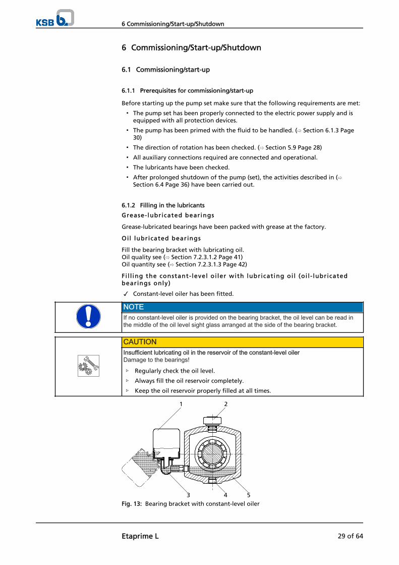
Fi l l ing the constant- level oi ler with lubricat ing oi l (oi l - lubr icatedbearings only)
✓ Constant-level oiler has been fitted.
NOTEIf no constant-level oiler is provided on the bearing bracket, the oil level can be read inthe middle of the oil level sight glass arranged at the side of the bearing bracket.
CAUTIONInsufficient lubricating oil in the reservoir of the constant-level oilerDamage to the bearings!
▷ Regularly check the oil level.
▷ Always fill the oil reservoir completely.
▷ Keep the oil reservoir properly filled at all times.
1 2
3 4 5Fig. 13: Bearing bracket with constant-level oiler
6 Commissioning/Start-up/Shutdown
Etaprime L 29 of 64

1 Constant-level oiler 2 Vent plug3 Connection elbow of the constant-level
oiler4 Screwed plug
5 Bearing bracket
1. Pull out the vent plug (2).
2. Hinge down the reservoir of the constant-level oiler (1) from the bearing bracket(5) and hold in this position.
3. Fill in oil through the hole for the vent plug until the oil reaches the connectionelbow of the constant-level oiler (3).
4. Completely fill the reservoir of the constant-level oiler (1).
5. Snap the constant-level oiler (1) back into its operating position.
6. Fit the vent plug (2) again.
7. After approximately 5 minutes, check the oil level in the glass reservoir of theconstant-level oiler (1). The oil reservoir must be properly filled at all times to provide an optimum oillevel. Repeat steps 1-6, if necessary.
8. To check the function of the constant-level oiler (1), slowly drain some oil via thescrewed plug (4) until air bubbles can be seen in the oil reservoir.
NOTEAn excessively high oil level can lead to a temperature rise and to leakage of the fluidhandled or oil.
6.1.3 Filling and venting the pump
DANGERAn explosive atmosphere forms inside the pumpRisk of explosion!
▷ Before starting up the pump set, vent the pump and fill it with the fluid to behandled.
▷ Combustible fluids are not permitted.
CAUTIONIncreased wear due to dry runningDamage to the pump set!
▷ Never operate the pump set without liquid fill.
▷ Never close the shut-off element in the suction line and/or supply line duringpump operation.
1. Vent the pump and fill it with the fluid to be handled.Connection 6B can be used for venting (see drawing of auxiliary connections).
2. Fully open the shut-off valve in the suction line.
3. Fully open all auxiliary feed lines (barrier fluid, flushing liquid, etc), if applicable.
6.1.4 Final check
1. Remove the coupling guard and step guard, if any.
2. Check the coupling alignment; re-align the coupling, if required. (⇨ Section 5.6Page 24)
3. Check that the coupling and shaft can easily be rotated by hand.
4. Re-install the coupling guard and step guard, if any.
5. Check the distance between coupling and coupling guard.The coupling guard must not touch the coupling.
6 Commissioning/Start-up/Shutdown
30 of 64 Etaprime L

6.1.5 Start-up
DANGERThe permissible pressure and temperature limits will be exceeded if the pump isoperated with the suction and discharge lines closedRisk of explosion!Leakage of hot or toxic fluids!
▷ Never operate the pump with the shut-off valves in the suction line and/ordischarge line closed.
▷ Never operate the pump against a closed swing check valve.
▷ Always wait until the pump has reached full rotational speed and priming hasbeen completed before adjusting the shut-off valve in the discharge line to theduty point.
DANGERExcessive temperatures due to dry running or excessive gas content in the fluid handledExplosion hazard!Damage to the pump set!
▷ Never operate the pump set without liquid fill.
▷ Prime the pump as specified. (⇨ Section 6.1.3 Page 30)
▷ Always operate the pump within the permissible operating range.
CAUTIONAbnormal noises, vibrations, temperatures or leakageDamage to the pump!
▷ Switch off the pump (set) immediately.
▷ Eliminate the causes before returning the pump set to service.
✓ The piping system connected to the pump set has been cleaned.
✓ The pump has been vented and filled with the fluid to be handled.
✓ The filling and venting lines have been closed.
✓ If a check valve is installed in the suction line: The volute casing and the suction line have been filled with the fluid to behandled.
✓ The pump can be started up against a closed valve.
✓ If no check valve is installed in the suction line: The volute casing has been primed with the fluid to be handled.
✓ No back pressure on the discharge side.
✓ The shut-off element is open.
CAUTIONStart-up against open discharge lineOverloading of the motor!
▷ Use a soft starter.
▷ Use speed control.
▷ Make sure the power reserve of the motor is sufficient.
6 Commissioning/Start-up/Shutdown
Etaprime L 31 of 64

DANGERSeal leakage at operating temperatureHot or toxic fluid may escape!
▷ Once the operating temperature has been reached, re-tighten the hexagon nutsat the casing/discharge cover.
▷ Check the coupling alignment. Re-align the coupling if required.
1. After the operating temperature has been reached and/or in the event ofleakage, switch off the pump set and retighten the bolts between lantern andcasing.
2. Check the coupling alignment and re-align the coupling, if required.
Pr iming t ime
For a 1-metre horizontal length of the suction line and DN suction line = DN pump,the priming times are as follows:
Pump size4) Priming time [sec]
at a speed n = 2900 rpm
and a static head of ... mSU 2 m 4 m 5 m 6 m 7 m 8 m
25-100 17 40 145 415 - - -32-120 30 90 135 190 255 36040-110 60 100 215 420 - -40-140 25 30 70 125 220 355 60050-130 50 120 195 260 345 44050-160 30 70 105 170 265 43065-150 60 120 165 260 375 57065-180 35 30 50 75 100 145 20080-170 50 100 135 180 225 31080-190 40 70 105 160 185 24080-200 30 50 75 105 155 200
100-240.1 30 70 95 120 150 190100-240 35 70 85 110 160 -125-260 35 80 105 130 160 190
Pump size4) Priming time [sec]
at a speed n = 3500 rpm
and a static head of ... mSU 2 m 4 m 5 m 6 m 7 m 8 m
25-100 17 30 85 135 - - -32-120 20 60 105 140 175 25040-110 30 85 125 200 265 47040-140 25 25 50 85 120 145 23050-130 30 90 140 190 245 30050-160 25 55 75 150 215 28065-150 40 80 125 170 225 37065-180 35 20 40 65 90 105 15080-170 30 80 105 130 165 22080-190 30 55 75 100 125 16080-200 25 40 55 80 125 160
100-240.1 25 60 85 115 145 180100-240 25 70 85 100 155 360
4) Stainless steel variant not available for all pump sizes.
6 Commissioning/Start-up/Shutdown
32 of 64 Etaprime L

Pump size4) Priming time [sec]
at a speed n = 1450 rpm
and a static head of ... mSU 1 m 2 m 3 m 4 m 5 m 6 m 7 m 8 m
25-100 17 130 - - - - - - -32-120 100 210 - - - - - -40-110 120 - - - - - - -40-140 25 130 - - - - - - -50-130 210 410 - - - - - -50-160 210 430 - - - - - -65-150 190 350 540 - - - - -65-180 35 90 140 220 370 - - - -80-170 110 180 280 480 - - - -80-190 100 110 200 310 - - - -80-200 70 110 190 270 320 420 - -
100-240.1 130 150 220 300 440 - - -100-240 110 160 270 480 - - - -125-260 60 70 110 160 200 330 430 610
Pump size4) Priming time [sec]
at a speed n = 1750 rpm
and a static head of ... mSU 1 m 2 m 3 m 4 m 5 m 6 m 7 m 8 m
25-100 17 70 170 - - - - - -32-120 80 150 260 - - - - -40-110 90 180 - - - - - -40-140 25 80 150 200 - - - - -50-130 130 240 380 - - - - -50-160 130 260 480 - - - - -65-150 140 260 350 430 - - - -65-180 35 80 110 170 220 330 - - -80-170 90 130 200 320 480 - - -80-190 80 100 130 160 210 390 - -80-200 60 100 160 230 280 350 - -
100-240.1 90 110 140 210 260 400 - -100-240 80 100 140 200 300 - - -125-260 50 60 80 115 170 220 300 400
6.1.6 Checking the shaft seal
The mechanical seal only leaks slightly or invisibly (as vapour) during operation.Mechanical seals are maintenance-free.
6.1.7 Shutdown
CAUTIONHeat build-up inside the pumpDamage to the shaft seal!
▷ Depending on the type of installation, the pump set requires sufficient after-runtime – with the heat source switched off – until the fluid handled has cooleddown.
✓ The shut-off element in the suction line is and remains open.
1. Close the shut-off element in the discharge line.
Mechanical seal
6 Commissioning/Start-up/Shutdown
Etaprime L 33 of 64

2. Switch off the motor and make sure the pump set runs down smoothly to astandstill.
NOTEIf the discharge line is equipped with a non-return or check valve, the shut-off elementmay remain open as long as there is back pressure.
For prolonged shutdown periods:
1. Close the shut-off element in the suction line.
2. Close the auxiliary connections. If the fluid handled is fed in under vacuum, also supply the shaft seal with barrierfluid during standstill.
CAUTIONRisk of freezing during prolonged pump shutdown periodsDamage to the pump!
▷ Drain the pump and the cooling/heating chambers (if any) or otherwise protectthem against freezing.
6.2 Operating limits
DANGERRisk of ignition by friction, impact, frictional sparks or thermal shock if handlingcombustible fluidsRisk of explosion!
▷ Combustible fluids are not permitted.
▷ The pump casing must not contain more than 7.5 % magnesium (seeEN 13463-1).
DANGERNon-compliance with operating limits for pressure, temperature and speedExplosion hazard!Hot or toxic fluid may escape!
▷ Comply with the operating data indicated in the data sheet.
▷ Avoid prolonged operation against a closed shut-off element.
▷ Never operate the pump at temperatures exceeding those specified in the datasheet or on the name plate unless the written consent of the manufacturer hasbeen obtained.
6.2.1 Ambient temperature
CAUTIONOperation outside the permissible ambient temperatureDamage to the pump (set)!
▷ Observe the specified limits for permissible ambient temperatures.
Observe the following parameters and values during operation:
Table 9: Permissible ambient temperatures
Permissible ambient temperature ValueMaximum 40 °CMinimum See data sheet.
6 Commissioning/Start-up/Shutdown
34 of 64 Etaprime L

6.2.2 Switching frequency
DANGERExcessive surface temperature of the motorExplosion hazard!Damage to the motor!
▷ In case of explosion-proof motors, observe the frequency of starts specified inthe manufacturer's product literature.
The frequency of starts is usually determined by the maximum temperature increaseof the motor. This largely depends on the power reserves of the motor in steady-state operation and on the starting conditions (d.o.l., star-delta, moments of inertia,etc). If the start-ups are evenly spaced over the period indicated, the following limitscan be used for orientation for start-up with the discharge-side gate valve slightlyopen:
Table 10: Switching frequency
Shaft unit5) Maximum switching frequency[start-ups/hour]
Etaprime GL Etaprime CL17 6 625 12 635 12 6
CAUTIONRe-start while motor is still running downDamage to the pump (set)!
▷ Do not re-start the pump set before the pump rotor has come to a standstill.
6.2.3 Flow rate
Table 11: Flow rate
Minimum flow rate Maximum flow rate≈ 15 % of Qopt. 6) See hydraulic characteristic curves
The calculation formula below can be used to check if an additional heat build-upcould lead to a dangerous temperature increase at the pump surface.
Table 12: Key
Symbol Description Unitc Specific heat capacity J/kg Kg Gravitational constant m/s²H Pump head mTf Temperature of the fluid handled °C
To Temperature at the casing surface °C
Pump efficiency at duty point -Temperature difference °C
5) Shaft unit see data sheet.6) Duty point at maximum efficiency
6 Commissioning/Start-up/Shutdown
Etaprime L 35 of 64

6.2.4 Density of the fluid handled
The power input of the pump increases in proportion to the density of the fluidhandled.
CAUTIONImpermissibly high density of the fluid handledMotor overload!
▷ Observe the information on fluid density indicated in the data sheet.
▷ Make sure the power reserve of the motor is sufficient.
DANGERDevelopment of gas-fluid mixtures when pumping combustible fluids.Risk of explosion!Damage to the pump set!
▷ Combustible fluids are not permitted.
6.2.5 Abrasive fluids
Do not exceed the maximum permissible solids content specified in the data sheet.When the pump handles fluids containing abrasive substances, increased wear of thehydraulic system and the shaft seal are to be expected. In this case, reduce theintervals commonly recommended for servicing and maintenance.
6.3 Shutdown/storage/preservation
6.3.1 Measures to be taken for shutdown
The pump (set) remains instal led
✓ Sufficient fluid is supplied for the operation check run of the pump.
1. Start up the pump (set) regularly once a month or once every three months forapproximately five minutes during prolonged shutdown periods. This will prevent the formation of deposits within the pump and the pumpintake area.
The pump (set) i s removed from the pipe and stored
✓ The pump has been properly drained (⇨ Section 7.3 Page 43) and the safetyinstructions for dismantling the pump have been observed. (⇨ Section 7.4.1 Page44)
1. Spray-coat the inside wall of the pump casing, and in particular the impellerclearance areas, with a preservative.
2. Spray the preservative through the suction and discharge nozzles.It is advisable to then close the pump nozzles (e.g. with plastic caps or similar).
3. Oil or grease all blank parts and surfaces of the pump (with silicone-free oil andgrease, food-approved if required) to protect them against corrosion. Observe the additional instructions. (⇨ Section 3.2 Page 14)
If the pump set is to be stored temporarily, only preserve the wetted componentsmade of low alloy materials. Commercially available preservatives can be used for thispurpose. Observe the manufacturer's instructions for application/removal.
Observe any additional instructions and information provided. (⇨ Section 3 Page 13)
6.4 Returning to service after storage
For returning the pump to service observe the sections on commissioning/start-up (⇨Section 6.1 Page 29) and the operating limits (⇨ Section 6.2 Page 34) .
6 Commissioning/Start-up/Shutdown
36 of 64 Etaprime L

In addition, carry out all servicing/maintenance operations before returning thepump (set) to service. (⇨ Section 7 Page 38)
WARNINGFailure to re-install or re-activate protective devicesRisk of personal injury from moving parts or escaping fluid!
▷ As soon as the work is complete, re-install and/or re-activate any safety-relevantand protective devices.
NOTEIf the pump has been out of service for more than one year, replace all elastomer seals.
6 Commissioning/Start-up/Shutdown
Etaprime L 37 of 64

7 Servicing/Maintenance
7.1 Safety regulations
DANGERImproperly serviced pump setExplosion hazard!Damage to the pump set!
▷ Service the pump set regularly.
▷ Prepare a maintenance schedule with special emphasis on lubricants, shaft sealand coupling.
The operator ensures that all maintenance, inspection and installation work isperformed by authorised, qualified specialist personnel who are thoroughly familiarwith the manual.
WARNINGPump set started up inadvertentlyRisk of injury by moving parts!
▷ Always make sure the electrical connections are disconnected before carryingout work on the pump set.
▷ Make sure that the pump set cannot be started up accidentally.
WARNINGFluids posing a health hazard or hot fluidsRisk of personal injury!
▷ Observe all relevant laws.
▷ When draining the fluid take appropriate measures to protect persons and theenvironment.
▷ Decontaminate pumps handling fluids posing a health hazard.
A regular maintenance schedule will help avoid expensive repairs and contribute totrouble-free, reliable operation of the pump (set) with a minimum of maintenanceexpenditure and work.
NOTEAll maintenance, service and installation work can be carried out by KSB Service. Findyour contact in the attached "Addresses" booklet or on the Internet at www.ksb.com/contact".
Never use force when dismantling and reassembling a pump set.
7 Servicing/Maintenance
38 of 64 Etaprime L

7.2 Servicing/inspection
7.2.1 Supervision of operation
DANGERAn explosive atmosphere forms inside the pumpRisk of explosion!
▷ Combustible fluids are not permitted.
▷ The pump internals in contact with the fluid to be handled, including the sealchamber and auxiliary systems must be filled with the fluid to be handled at alltimes.
▷ Provide sufficient inlet pressure.
▷ Provide an appropriate monitoring system.
DANGERIncorrectly serviced shaft sealExplosion hazard!Fire hazard!Leakage of hot, toxic fluids!Damage to the pump set!
▷ Regularly service the shaft seal.
DANGERExcessive temperatures as a result of bearings running hot or defective bearing sealsExplosion hazard!Fire hazard!Damage to the pump set!
▷ Regularly check the lubricant level.
▷ Regularly check the rolling element bearings for running noises.
CAUTIONIncreased wear due to dry runningDamage to the pump set!
▷ Never operate the pump set without liquid fill.
▷ Never close the shut-off element in the suction line and/or supply line duringpump operation.
CAUTIONImpermissibly high temperature of fluid handledDamage to the pump!
▷ Prolonged operation against a closed shut-off element is not permitted (heatingup of the fluid).
▷ Observe the temperature limits in the data sheet and in the section onOperating limits. (⇨ Section 6.2 Page 34)
While the pump is in operation, observe and check the following:
▪ The pump must run quietly and free from vibrations at all times.
▪ In case of oil lubrication, ensure the oil level is correct. (⇨ Section 6.1.2 Page 29)
▪ Check the shaft seal. (⇨ Section 6.1.6 Page 33)
▪ Check the static seals for leakages.
7 Servicing/Maintenance
Etaprime L 39 of 64

▪ Check the rolling element bearings for running noises.Vibrations, noise and an increase in current input occurring during unchangedoperating conditions indicate wear.
▪ Monitor the correct functioning of any auxiliary connections.
▪ Monitor the stand-by pump.To make sure that the stand-by pumps are ready for operation, start them uponce a week.
▪ Monitor the bearing temperature.The bearing temperature must not exceed 90 °C (measured on the outside of thebearing bracket).
CAUTIONOperation outside the permissible bearing temperatureDamage to the pump!
▷ The bearing temperature of the pump (set) must never exceed 90 °C (measuredon the outside of the bearing bracket).
NOTEAfter commissioning, increased temperatures may occur at grease-lubricated rollingelement bearings due to the running-in process. The final bearing temperature is onlyreached after a certain period of operation (up to 48 h depending on the conditions).
7.2.2 Inspection work
DANGERExcessive temperatures caused by friction, impact or frictional sparksExplosion hazard!Fire hazard!Damage to the pump set!
▷ Regularly check the coupling guard, plastic components and other guards ofrotating parts for deformation and sufficient distance from rotating parts.
7.2.2.1 Checking the coupling
Check the flexible elements of the coupling. Replace these parts in due time if thereis any sign of wear.
7.2.2.2 Checking the clearance gaps
For checking the clearance gaps remove the impeller, if required. (⇨ Section 7.4.5Page 45)If the axial clearance is larger or smaller than permitted (see the following table), re-adjust it in accordance with the table below.The clearance gaps indicated refer to the axial clearance between the impeller vanesand the pump casing.
Table 13: Clearance gap between impeller face and volute casing wall:
Etaprime GL Etaprime CLClearance as-new 0.2 mm 0.2 - 0.3 mm
Maximum clearance 0.5 mm 0.7 mm
If the maximum clearance is exceeded, insert a disc with a thickness of 0.1 mm andadjust the clearance to the as-new value.
7 Servicing/Maintenance
40 of 64 Etaprime L

7.2.2.3 Cleaning filters
CAUTIONInsufficient inlet pressure due to clogged filter in the suction lineDamage to the pump!
▷ Monitor contamination of filter with suitable means (e.g. differential pressuregauge).
▷ Clean filter in appropriate intervals.
7.2.2.4 Checking the bearing seals
DANGERExcessive temperatures caused by mechanical contactRisk of explosion!Damage to the pump set!
▷ Check correct seating of axial sealing rings mounted on the shaft.Only gentle contact of the sealing lip shall be established.
7.2.3 Lubrication and lubricant change of rolling element bearings
DANGERExcessive temperatures as a result of bearings running hot or defective bearing sealsExplosion hazard!Fire hazard!Damage to the pump set!
▷ Regularly check the condition of the lubricant.
7.2.3.1 Oil lubrication
The rolling element bearings are usually lubricated with mineral oil.
7.2.3.1.1 Intervals
Table 14: Oil change intervals
Oil change IntervalInitial oil change after 300 operating hoursFurther oil changes after 3000 operating hours7)
7.2.3.1.2 Oil quality
Table 15: Oil quality8)
Code Symbol toDIN 51502
Properties
Lubricatingoil C 46CL 46CLP 46
□ Kinematic viscosity at 40 °C 46 ± 4 mm²/sFlash point (to Cleveland) +175 °CSolidification point (pour point) -15 °CApplication temperature9) Higher than
permissible bearingtemperature
7) At least once a year8) To DIN 515179) For ambient temperatures below -10 °C use a different suitable type of lubricant oil. Request particulars.
7 Servicing/Maintenance
Etaprime L 41 of 64

7.2.3.1.3 Oil quantity
Table 16: Oil quantity per oil-lubricated DIN 625 radial ball bearing
Part No. Description Shaft unit 10) Code Oil quantity perbearing bracket
[l]321 Radial ball bearing 25 6305 C3 0.2
35 6307 C3 0.35
7.2.3.1.4 Changing the oil
WARNINGLubricants posing a health hazardHazard to persons and the environment!
▷ When draining the lubricant take appropriate measures to protect persons andthe environment.
▷ Observe all legal regulations on the disposal of liquids posing a health hazard.
1 2 3Fig. 14: Bearing bracket with constant-level oiler
1 Constant-level oiler 2 Screwed plug3 Bearing bracket
✓ A suitable container for the used oil is on hand.
1. Place the container underneath the screwed plug.
2. Undo the screwed plug (2) at the bearing bracket (3) and drain the oil.
3. Once the bearing bracket (3) has been drained, re-insert and re-tighten thescrewed plug (2).
4. Re-fill with oil. (⇨ Section 6.1.2 Page 29)
7.2.3.2 Grease lubrication
The bearings are supplied packed with high-quality lithium-soap grease.
7.2.3.2.1 Intervals
Under normal conditions the grease-lubricated bearings will run for 15,000 operatinghours or 2 years. Under unfavourable operating conditions (e.g. high roomtemperature, high atmospheric humidity, dustladen air, aggressive industrialatmosphere etc.), check the bearings earlier and clean and relubricate them, ifrequired.
10) Shaft unit see data sheet.
7 Servicing/Maintenance
42 of 64 Etaprime L

7.2.3.2.2 Grease quality
Optimum grease propert ies for rol l ing element bear ings
▪ High melting point lithium soap base grease
▪ Free of resin and acid
▪ Not liable to crumble
▪ With good rust-preventive characteristics
▪ Penetration number between 2 and 3 (corresponding to a worked penetration of220 to 295 mm/10)
▪ Drop point ≥ 175 °C
If required, the bearings may be lubricated with greases of other soap bases.Make sure to remove any old grease and rinse the bearings thoroughly.
7.2.3.2.3 Grease quantity
Table 17: Grease quantity per grease-lubricated DIN 625 radial ball bearing
Part No. Description Shaft unit11) Code Grease quantityper bearing
[g]321.01 Radial ball bearing 17 3203-C3 2.5321.02 Radial ball bearing 3203 2R9 2.5
321 Radial ball bearing 25 6305 Z C3 535 6307 Z C3 10
7.2.3.2.4 Changing the grease
CAUTIONMixing greases of differing soap basesChanged lubricating qualities!
▷ Thoroughly clean the bearings.
▷ Adjust the re-lubrication intervals to the grease used.
1. Only half-fill the bearing cavities with grease.
7.3 Drainage/disposal
WARNINGFluids posing a health hazardHazardous to persons and the environment!
▷ Collect and properly dispose of flushing liquid and any fluid residues.
▷ Wear safety clothing and a protective mask, if required.
▷ Observe all legal regulations on the disposal of fluids posing a health hazard.
1. For draining the fluid handled use connection 6B (see drawing of auxiliaryconnections).
2. If noxious, explosive, hot or other hazardous fluids have been handled, flush thepump.Always flush and clean the pump before transporting it to the workshop. Providea cleaning record for the pump.
11) Shaft unit see data sheet.
7 Servicing/Maintenance
Etaprime L 43 of 64

7.4 Dismantling the pump set
7.4.1 General notes/Safety regulations
WARNINGUnqualified personnel performing work on the pump (set)Risk of personal injury!
▷ Always have repair and maintenance work performed by specially trained,qualified personnel.
WARNINGHot surfaceRisk of personal injury!
▷ Allow the pump set to cool down to ambient temperature.
Observe the general safety instructions and information. (⇨ Section 7.1 Page 38)
For any work on the motor, observe the instructions of the relevant motormanufacturer.
For dismantling and reassembly observe the exploded view and the general assemblydrawing. (⇨ Section 9.1 Page 56)
NOTEAll maintenance, service and installation work can be carried out by KSB Service. Findyour contact in the attached "Addresses" booklet or on the Internet at www.ksb.com/contact".
DANGERInsufficient preparation of work on the pump (set)Risk of personal injury!
▷ Properly shut down the pump set. (⇨ Section 6.1.7 Page 33)
▷ Close the shut-off elements in the suction and discharge line.
▷ Drain the pump and release the pump pressure. (⇨ Section 7.3 Page 43)
▷ Close any auxiliary connections.
▷ Allow the pump set to cool down to ambient temperature.
NOTEAfter a prolonged period of operation the individual parts may be hard to pull off theshaft. If this is the case, use a brand name penetrating agent and/or - if possible - anappropriate pull-off device.
7.4.2 Preparing the pump set
1. Disconnect the power supply (e.g. at the motor).
2. Disconnect and remove all auxiliary pipework.
3. Remove the coupling guard.
4. Remove the coupling spacer, if any.
5. Drain the oil fill of oil-lubricated bearings. (⇨ Section 7.2.3.1.4 Page 42)
7.4.3 Dismantling the motor
NOTEFor pump sets with spacer-type couplings, the back pull-out unit can be removed whilethe motor remains bolted to the baseplate.
7 Servicing/Maintenance
44 of 64 Etaprime L

1. Disconnect the motor from the power supply.
2. Unbolt the motor from the baseplate.
3. Shift the motor to separate it from the pump.
WARNINGMotor tipping overRisk of squashing hands and feet!
▷ Suspend or support the motor to prevent it from tipping over.
7.4.4 Removing the back pull-out unit
✓ The notes and steps stated in (⇨ Section 7.4.1 Page 44) to (⇨ Section 7.4.3 Page44) have been observed/carried out.
✓ On pump sets without spacer-type coupling, the motor has been removed.
WARNINGBack pull-out unit tipping overRisk of squashing hands and feet!
▷ Suspend or support the bearing bracket at the pump end.
1. If required, suspend or support bearing bracket 330 or bearing housing 350 toprevent them from tipping over.
2. Unbolt support foot 183 from the baseplate.
3. Undo nut 920.01 at the volute casing.
4. Pull the back pull-out unit out of the volute casing.
5. Remove and dispose of O-ring 412.35.
6. Place the back pull-out unit on a clean and level surface.
7.4.5 Removing the impeller
✓ The notes and steps stated in (⇨ Section 7.4.1 Page 44) to (⇨ Section 7.4.4 Page45) have been observed/carried out.
✓ The back pull-out unit is kept in a clean and level assembly area.
1. Undo impeller nut 920.95 (right-hand thread).
2. Remove impeller 230 with an impeller removal device.
3. Place impeller 230 on a clean and level surface.
4. Remove keys 940.01 from shaft 210.
5. Pull the spacer discs off the shaft.
7.4.6 Dismantling the mechanical seal
✓ The notes and steps stated in (⇨ Section 7.4.1 Page 44) to (⇨ Section 7.4.5 Page45) have been observed/carried out.
✓ The back pull-out unit is kept in a clean and level assembly area.
1. Remove the rotating part of the mechanical seal (spring-loaded ring) from shaftsleeve 523.
2. Undo nuts 920.24 (if any) at casing cover 161.
3. Remove casing cover 161 from bearing bracket 330, if applicable.
4. Remove the stationary part of the mechanical seal (seat ring) from casing cover161 or bearing housing 350.
5. Pull shaft sleeve 523 (if any) off shaft 210.
6. Remove and dispose of O-ring 412.35.
7 Servicing/Maintenance
Etaprime L 45 of 64

7.4.7 Dismantling the bearings
Oi l lubr icat ion
✓ The notes and steps stated in (⇨ Section 7.4.1 Page 44) to (⇨ Section 7.4.6 Page45) have been observed/carried out.
✓ The bearing bracket is kept in a clean and level assembly area.
1. Unscrew the socket head cap screw in the coupling hub.
2. Pull the coupling hub off shaft 210 with a special puller.
3. Remove key 940.02.
4. Remove thrower 507.
5. Remove bearing covers 360.2 at the pump and motor end.
6. Remove hexagon head bolts 901.1 and gaskets 400.2.
7. Press shaft 210 out of the shaft seat.
8. Remove radial ball bearing 321 and place it on a clean and level surface.
9. Dispose of gaskets 400.2.
Grease lubricat ion
✓ The notes and steps stated in (⇨ Section 7.4.1 Page 44) to (⇨ Section 7.4.6 Page45) have been observed/carried out.
✓ The bearing bracket is kept in a clean and level assembly area.
1. Unscrew the socket head cap screw in the coupling hub.
2. Pull the coupling hub off shaft 210 with a special puller.
3. Remove key 940.02.
4. Remove axial sealing rings 411.02 and 411.03, if applicable.
5. Remove thrower 507.02, if any.
6. Remove bearing covers 360.01 and 360.02.
7. Remove circlips 932 / 932.02.
8. Press shaft 210 out of the bearing seats.
9. Place radial ball bearing 321 on a clean and level surface.
7.5 Reassembling the pump set
7.5.1 General notes/Safety regulations
CAUTIONImproper reassemblyDamage to the pump!
▷ Reassemble the pump (set) in accordance with the general rules of soundengineering practice.
▷ Use original spare parts only.
Always reassemble the pump in accordance with the corresponding general assemblydrawing or exploded view.
Check O-rings for any damage and replace by new O-rings, if required.
Always use new gaskets, making sure that they have the same thickness as the oldones.
Always fit gaskets of asbestos-free materials or graphite without using lubricants(e.g. copper grease, graphite paste).
Avoid the use of assembly adhesives, if possible.
Should an assembly adhesive be required after all, use a commercially availablecontact adhesive (e.g. "Pattex") or sealant (e.g. HYLOMAR or Epple 33).
Sequence
Seal elements
Assembly adhesives
7 Servicing/Maintenance
46 of 64 Etaprime L

Only apply adhesive at selected points and in thin layers.
Never use quick-setting adhesives (cyanoacrylate adhesives).
Coat the locating surfaces of the individual components with graphite or similarbefore reassembly.
For reassembly, tighten all screws as specified in this manual. (⇨ Section 7.6 Page50)
7.5.2 Installing the bearings
Oi l lubr icat ion
✓ The individual parts are kept in a clean and level assembly area.
✓ All disassembled parts have been cleaned and checked for wear.
✓ Any damaged or worn parts have been replaced by original spare parts.
✓ The sealing surfaces have been cleaned.
1. Press radial ball bearing 321 onto shaft 210.
2. Insert the pre-assembled shaft into bearing bracket 330.
3. Fit new gasket 400.2.
4. Fasten bearing cover 360.2 with hexagon head bolts 901.1; take care not todamage radial shaft seal 421.
5. Fit thrower 507.
6. Insert keys 940.02.
7. Fit the coupling half on the motor-end shaft stub.
8. Fasten the coupling hub with a socket head cap screw.
Grease lubricat ion
5b)
a)1
2
34
Fig. 15: Installing the radial ball bearing a) shaft units 25 and 35 b) shaft unit 17
1 Bearing bracket 2 Cover plate3 Radial ball bearing 4 Shaft5 Bearing housing
✓ The individual parts are kept in a clean and level assembly area.
✓ All disassembled parts have been cleaned and checked for wear.
✓ Any damaged or worn parts have been replaced by original spare parts.
✓ The sealing surfaces have been cleaned.
1. Press radial ball bearing 321 onto shaft 210.Make sure that the bearing side with the cover plate rests against the shaftshoulder (see illustration: Installing the radial ball bearing).
2. Push the pre-assembled shaft into bearing bracket 330 or bearing housing 350.
3. Fit circlips 932.
4. Fit bearing cover 360.1, if any.
5. Fit axial sealing rings 411.
6. Insert keys 940.02.
Tightening torques
7 Servicing/Maintenance
Etaprime L 47 of 64

7. Fit the coupling half on the motor-end shaft stub.
8. Fasten the coupling hub with a socket head cap screw.
7.5.3 Installing the mechanical seal
Always observe the following rules when installing the mechanical seal:
▪ Work cleanly and accurately.
▪ Only remove the protective wrapping of the contact faces immediately beforeassembly takes place.
▪ Prevent any damage to the sealing surfaces or O-rings.
✓ The notes and steps stated in (⇨ Section 7.5.1 Page 46) to (⇨ Section 7.5.2 Page47) have been observed/carried out.
✓ The assembled bearing as well as the individual parts are kept in a clean andlevel assembly area.
✓ All disassembled parts have been cleaned and checked for wear.
✓ Any damaged or worn parts have been replaced by original spare parts.
✓ The sealing surfaces have been cleaned.
1. Clean shaft sleeve 523, and touch up any score marks or scratches with apolishing cloth.If score marks or scratches are still visible, replace shaft sleeve 523.
2. Push shaft sleeve 523 (if any) onto shaft 210 with new gasket 400.01.
3. Clean the seat ring location in casing cover 161.
CAUTIONElastomers in contact with oil/greaseShaft seal failure!
▷ Use water as assembly lubricant.
▷ Never use oil or grease as assembly lubricant.
4. Carefully insert the seat ring.Press in evenly.
5. Fit casing cover 161 into the locating fit of bearing bracket 330 or bearinghousing 350.
6. Fit and tighten nuts 920.4, if any.
NOTETo reduce friction forces when assembling the seal, wet the shaft sleeve and the seatring location with water.
7. Remove the rotating part of the mechanical seal (spring-loaded ring) from shaftsleeve 523.
UG1026788:063/1L
d 1
1 2 3 4 5Fig. 16: Mechanical seal chamber
Installing the mechanicalseal
7 Servicing/Maintenance
48 of 64 Etaprime L

1 Impeller 2 Spacer discs3 Shaft sleeve 4 Mechanical seal5 Casing cover
Table 18: Installation dimensions of the mechanical seal
Shaft unit12) Installation dimension d1 Installation dimension L
17 16 mm l1K = 35
25 28 mm I1N = 50
35 38 mm I1N = 55
7.5.4 Fitting the impeller
✓ The notes and steps stated in (⇨ Section 7.5.1 Page 46) to (⇨ Section 7.5.3 Page48) have been observed/carried out.
✓ The assembled bearing bracket as well as the individual parts are kept in a cleanand level assembly area.
✓ All disassembled parts have been cleaned and checked for wear.
✓ Any damaged or worn parts have been replaced by original spare parts.
✓ The sealing surfaces have been cleaned.
1. Push the spacer discs onto the shaft. (Always use the same number and type ofspacer discs as originally fitted at the factory!)
2. Insert key 940.01 and push impeller 230 onto shaft 210.
3. Fasten impeller nut 920.95, lockwasher 930.95 and disc 550.01, if any. (See table:Tightening torques of screwed connections at the pump (⇨ Section 7.6 Page50)).
4. Observe, check and re-adjust the axial clearance. (⇨ Section 7.2.2.2 Page 40)
DANGERExcessive temperatures caused by mechanical contactRisk of explosion!Damage to the pump set!
▷ Check correct seating of axial joint rings mounted on the shaft. Only gentlecontact shall be established between the sealing lip and the shaft.
▷ Observe, check and re-adjust the axial clearance. (⇨ Section 7.2.2.2 Page 40)
CAUTIONRubbing contact between impeller and volute casingDamage to the impeller, casing, mechanical seal and bearing!
▷ Observe, check and re-adjust the axial clearance. (⇨ Section 7.2.2.2 Page 40)
NOTEAlways check the clearance gap.
7.5.5 Installing the back pull-out unit
WARNINGBack pull-out unit tipping overRisk of squashing hands and feet!
▷ Suspend or support the bearing bracket at the pump end.
12) Shaft unit see data sheet.
7 Servicing/Maintenance
Etaprime L 49 of 64
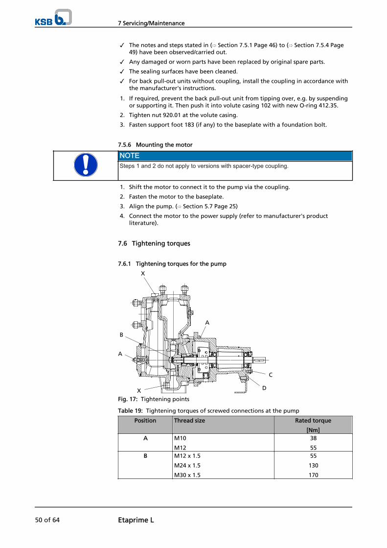
✓ The notes and steps stated in (⇨ Section 7.5.1 Page 46) to (⇨ Section 7.5.4 Page49) have been observed/carried out.
✓ Any damaged or worn parts have been replaced by original spare parts.
✓ The sealing surfaces have been cleaned.
✓ For back pull-out units without coupling, install the coupling in accordance withthe manufacturer's instructions.
1. If required, prevent the back pull-out unit from tipping over, e.g. by suspendingor supporting it. Then push it into volute casing 102 with new O-ring 412.35.
2. Tighten nut 920.01 at the volute casing.
3. Fasten support foot 183 (if any) to the baseplate with a foundation bolt.
7.5.6 Mounting the motor
NOTESteps 1 and 2 do not apply to versions with spacer-type coupling.
1. Shift the motor to connect it to the pump via the coupling.
2. Fasten the motor to the baseplate.
3. Align the pump. (⇨ Section 5.7 Page 25)
4. Connect the motor to the power supply (refer to manufacturer's productliterature).
7.6 Tightening torques
7.6.1 Tightening torques for the pump
A
X
B
A
X D
C
Fig. 17: Tightening points
Table 19: Tightening torques of screwed connections at the pump
Position Thread size Rated torque
[Nm]A M10
M12
38
55B M12 x 1.5
M24 x 1.5
M30 x 1.5
55
130
170
7 Servicing/Maintenance
50 of 64 Etaprime L

Position Thread size Rated torque
[Nm]C M8
M10
20
38D M12 125E M8
M10
M12
M16
20
38
55
130F M6
M8
M10
M12
15
38
38
55X 1/8
1/4
3/8
1/2
3/4
25
55
80
130
220
7.6.2 Tightening torques for the pump set
6
5
1 2 3 4Fig. 18: Tightening points of the pump set
Table 20: Tightening torques for the pump set
Position Thread size Ratedtorque
[Nm]
Description
1 M12
M16
M20
30
75
75
Pump on baseplate
2 M12 303 M24 x 1.5
M36 x 1.5
140
140
Levelling screws in baseplate
7 Servicing/Maintenance
Etaprime L 51 of 64

Position Thread size Ratedtorque
[Nm]
Description
4 M6
M8
M10
M12
M16
M20
M24
10
10
15
30
75
140
140
Motor on baseplate or
motor on levelling screws or shims
5 M6
M8
M10
13
18
44
Coupling (only for spacer-typecoupling made by Flender)
6 M6 10 Coupling guard
7.7 Spare parts stock
7.7.1 Ordering spare parts
Always quote the following data when ordering replacement or spare parts:
▪ Type series
▪ Material variant
▪ Size
▪ Seal code
▪ KSB order number
▪ Order item number
▪ Consecutive number
▪ Year of construction
Refer to the name plate for all data. (⇨ Section 4.3 Page 16)
Also supply the following data:
▪ Description
▪ Part No.
▪ Quantity of spare parts
▪ Delivery address
▪ Mode of dispatch (freight, mail, express freight, air freight)
Refer to the exploded view or general assembly drawing for part numbers anddescriptions. (⇨ Section 9.1 Page 56)
7.7.2 Recommended spare parts stock for 2 years' operation to DIN 24296
Table 21: Quantity of spare parts for recommended spare parts stock
Part No. Description Number of pumps (including stand-by pumps)2 3 4 5 6 and 7 8 and 9 10 and
more210 Shaft 1 1 1 2 2 2 20 %230 Impeller 1 1 1 2 2 2 20 %321.01/.02 Deep-groove ball bearing (set) 1 1 2 2 2 3 25 %33013) Bearing bracket - - - - - 1 2
13) For shaft units 25 and 35 (shaft unit see data sheet)
7 Servicing/Maintenance
52 of 64 Etaprime L

Part No. Description Number of pumps (including stand-by pumps)2 3 4 5 6 and 7 8 and 9 10 and
more35014) Bearing housing - - - - - 1 2
400.0113) Gasket 4 6 8 8 9 12 15 %
412.35/.6513) O-ring 4 6 8 8 9 12 15 %433.01 Mechanical seal 1 1 2 2 2 3 25 %52313) Shaft sleeve 2 2 2 3 3 4 50 %
7.7.3 Interchangeability of Etaprime L and B/BN pump components
Components featuring the same number in a column are interchangeable.
Table 22: Interchangeability of Etaprime L and Etaprime B/BN pump components andinterchangeability of components among each other
Size
Shaf
t u
nit
Description
Vo
lute
cas
ing
Cas
ing
co
ver
Shaf
t
Imp
elle
r
Rad
ial b
all b
eari
ng
Rad
ial b
all b
eari
ng
Bea
rin
g h
ou
sin
g
Mec
han
ical
sea
l
Shaf
t sl
eeve
Part No.
102
161
210
230
321.
01
321.
02
350
433.
01
523
25-100 17 ○* X* 1 ○* 1 2 1 1* X32-120 ○* X* 1 ○* 1 2 1 1* X40-110 ○* X* 1 ○* 1 2 1 1* X40-140 25 ○* ○* 2 ○* X 3 X 2* 1*50-130 ○* ○* 2 ○* X 3 X 2* 1*50-160 ○* ○* 2 ○* X 3 X 2* 1*65-150 ○* ○* 2 ○* X 3 X 2* 1*65-180 35 ○* ○* 3 ○* X 4 X 3* 2*80-170 ○* ○* 3 ○* X 4 X 3* 2*80-190 ○* ○* 3 ○* X 4 X 3* 2*80-200 ○* ○* 3 ○* X 4 X 3* 2*100-240.1 1* ○* 3 ○* X 4 X 3* 2*100-24015) 1 ○ 3 ○ X 4 X 3 2
125-26015) ○ ○ 3 ○ X 4 X 3 2
Table 23: Key to the symbols
Symbol Description* Component interchangeable with Etaprime B/BN○ Components differX Component not fitted
14) For shaft unit 17 (shaft unit see data sheet)15) Not available as Etaprime B/BN
7 Servicing/Maintenance
Etaprime L 53 of 64

8 Trouble-shootingPump delivers insufficient flow rate
Motor is overloaded
Excessive pump discharge pressure
Excessive bearing temperature
Leakage at the pump
Excessive leakage at the shaft seal
Vibrations during pump operation
Impermissible rise of temperature inside the pump
Table 24: Trouble-shooting
A B C D E F G H Possible cause Remedy16)
X Pump delivers against an excessivelyhigh discharge pressure.
Re-adjust to duty point.Check system for impurities.Fit a larger impeller.17)
Increase the speed (turbine, I.C. engine).X X X Pump or piping are not completely
vented or primed.Vent and/or prime.
X Supply line or impeller clogged. Remove deposits in the pump and/or piping.X Formation of air pockets in the piping. Alter piping layout.
Fit a vent valve.X X X Suction head is too high/NPSHavailable
(positive suction head) is too low.Check/alter liquid level.Install pump at a lower level.Fully open shut-off valve in the suction line.Change suction line if the friction losses in thesuction line are too high.Check any strainers installed/suction opening.Observe permissible speed of pressure fall.
X Air intake at the shaft seal. Clean barrier fluid duct, supply externalbarrier fluid, if necessary, or increase itspressure.Replace the shaft seal.
X Wrong direction of rotation Interchange two of the phases of the powercable.
X Speed is too low.17)
- Operation with frequency inverter
- Operation without frequency inverter
- Increase voltage/frequency at the FI in thepermissible range.- Check the voltage.
X X Wear of internal pump parts Replace worn parts by new ones. X X Pump back pressure is lower than
specified in the purchase order.Re-adjust to duty point.In the case of persistent overloading, turndown impeller.17)
X Density or viscosity of the fluid pumpedis higher than stated in the purchaseorder.
Contact KSB.
X Wrong shaft seal materials Change the material combination.17)
X X Speed is too high. Reduce speed.17)
X Tie bolts/sealing element defective. Fit new seal between pump casing and casingcover/discharge cover.Re-tighten the tie bolts.
X Worn shaft seal. Replace the shaft seal.Check flushing liquid / barrier fluid.
X X Score marks or roughness on shaftsleeve.
Replace the shaft sleeve.Replace the shaft seal.
A
B
C
D
E
F
G
H
16) Pump pressure must be released before attempting to remedy faults on parts which are subjected to pressure.17) Contact KSB.
8 Trouble-shooting
54 of 64 Etaprime L

A B C D E F G H Possible cause Remedy16)
X Dismantle to find out. Correct.Replace the shaft seal, if required.
X Vibrations during pump operation. Correct suction conditions.Re-align the pump set.Re-balance the impeller.Increase pressure at the pump suction nozzle.
X X X The pump set is misaligned. Re-align the pump set. X X X Pump is warped or sympathetic
vibrations in the piping.Check pipeline connections and secure fixingof pump; if required, reduce distancesbetween pipe clamps.Fix the pipelines using anti-vibration material.
X Insufficient or excessive quantity oflubricant or unsuitable lubricant.
Top up, reduce or change lubricant.
X Non-compliance with specified couplingdistance.
Correct distance according to the generalarrangement drawing.
X X Motor is running on two phases only. Replace the defective fuse.Check the electric cable connections.
X Operating voltage is too low. Increase the voltage. X Rotor is out of balance. Clean the impeller.
Re-balance the impeller. X Defective bearing(s) Fit new bearing(s). X X X Insufficient flow rate Increase the minimum flow rate. X Incorrect inflow of circulation liquid. Increase the free cross-section.
16) Pump pressure must be released before attempting to remedy faults on parts which are subjected to pressure.
8 Trouble-shooting
Etaprime L 55 of 64

9 Related Documents
9.1 Sectional Drawing and List of Components
9.1.1 Etaprime GL and CL with threaded connection and bearing housing (SU 17)
UG1026763:002/1
UG1026763:001/1
Fig. 19: Design: Single mechanical seal
[ Supplied in packaging units only
Part No. Description Part No. Description102 Volute casing 550.02/.03/.04 Disc210 Shaft 902.01 Stud230 Impeller 903.01/.02/.03/.04/.06/.08 Screwed plug321.01/.02 Radial ball bearing 920.01/.95 Nut350 Bearing housing 932.02 Circlip411.01 Joint ring 940.01/.02 Key412.35 O-ring 433.01 Mechanical seal Auxiliary connections504 Spacer ring 6 B Fluid drain507.01/.02 Thrower 6 D Fluid filling and venting
UG1026763:003/1UG1026763:055/1
Fig. 20: Design: Single mechanical seal with flushing system
9 Related Documents
56 of 64 Etaprime L

Part No. Description Part No. Description433.01 Mechanical seal (primary) 720.02/.03 Special part433.02 Mechanical seal (secondary) 903.08 Screwed plug504 Spacer ring 916.01/.02 Plug550.02/.04 Disc
9.1.2 Etaprime GL and CL with flanged connection and bearing bracket/greaselubrication (SU 25 and SU 35)
UG1026676:017/1
UG1026676:018/1 UG1026676:019/1a) b)Fig. 21: Design: Single-acting mechanical seal; a) Bolted-on casing cover, b) Impeller fastening for SU 35
[ Supplied in packaging units only
Part No. Description Part No. Description102 Volute casing 550.0118) Disc161 Casing cover 550.02/.04/.17 Disc164.01 Inspection cover 81-92.01 Cover plate183 Support foot 901.01/.02/.03 Hexagon head bolt
18) For SU 25 only; shaft unit see data sheet.
9 Related Documents
Etaprime L 57 of 64

Part No. Description Part No. Description210 Shaft 902.01/.17/.18/.19/.24 Stud230 Impeller 903.01/.02/.03/.04 Screwed plug321.01/.02 Radial ball bearing 920.01/.05/.17/.18/.19/.24/.95 Nut330 Bearing bracket 930.95 Safety device360.01/.02 Bearing cover 932.02/.03/.04/.05 Circlip400.01 Gasket 940.01/.02 Key411.01/.02/.03 Joint ring 412.35/.65 O-ring Auxiliary connections:433.01 Mechanical seal 6 B Fluid drain523 Shaft sleeve 6 D Fluid filling and venting525 19) Spacer sleeve
UG1026748:024/1
UG1026748:023/1
Fig. 22: Design: Single-acting mechanical seal with flushing system
Part No. Description Part No. Description161 Casing cover 731.04 Pipe union210 Shaft 81-92.01/.02 Cover plate400.01 Gasket 901.01 Hexagon head bolt433.01 Mechanical seal 903.05 Screwed plug523 Shaft sleeve 916.01 Plug720.01/.02 Spacer 932.03 Lockwasher
19) For SU 35 only (not shown in the drawing); shaft unit see data sheet.
9 Related Documents
58 of 64 Etaprime L

9.1.3 Etaprime GL and CL with flanged connection and bearing bracket/oillubrication (SU 25 and SU 35)
Design of pump and mechanical seal as described in (⇨ Section 9.1.2 Page 57).Difference: Oil-lubricated bearing bracket instead of grease-lubricated bearingbracket.
1211:172
B
Fig. 23: Constant-level oiler
[ Supplied in packaging units only
Part No. Description Part No. Description Part No. Description183 Support foot 55020) Disc 932 Circlip210 Shaft 638 Constant-level oiler 940.2 Key321 Radial ball bearing 672 Vent 940.3 Key330 Bearing bracket 81-92 Cover plate 360.2 Bearing cover 901.1-.3 Hexagon head bolt 8B Leakage drain400.2 Gasket 903.3 Screwed plug 13B Oil drain421 Lip seal 920.1/.5 Nut 13D Oil – filling and
venting507 Thrower 930.320) Safety device
20) Not shown in drawing
9 Related Documents
Etaprime L 59 of 64

10 EC Declaration of Conformity
Manufacturer: KSB AktiengesellschaftJohann-Klein-Straße 9
67227 Frankenthal (Germany)
The manufacturer herewith declares that the pump/pump set:
Etabloc, Etabloc SY, Etaline, Etaline SY, Etaline Z, Etachrom NC,Etachrom BC, Etanorm, Etanorm SYA, Etanorm GPV/CPV,
Etaprime L, Etaprime B/BN, Vitachrom
KSB order number: ...................................................................................................
▪ is in conformity with the provisions of the following directives as applicable in their current version:
– EC Machinery Directive 2006/42/EC
The manufacturer also declares that
▪ the following harmonised international standards have been applied:
– ISO 12100-1/A1, ISO 12100-2/A1,
– ISO 14121-1,
– EN 809/A1
Frankenthal, 29 December 2009
...........................................................
Name
Function
Responsible for compiling the technical documentationKSB AktiengesellschaftJohann-Klein-Straße 9
67227 Frankenthal (Germany)
10 EC Declaration of Conformity
60 of 64 Etaprime L

11 Certificate of Decontamination
Type ................................................................................................................................Order number/Order item number21) ................................................................................................................................ Delivery date ................................................................................................................................ Field of application: ................................................................................................................................ Fluid handled21) : ................................................................................................................................
Please tick where applicable21) :
⃞ ⃞ ⃞ ⃞radioactive explosive corrosive toxic
⃞ ⃞ ⃞ ⃞harmful bio-hazardous highly flammable safe
Reason for return21) : ................................................................................................................................ Comments: ................................................................................................................................ ................................................................................................................................ The pump/accessories have been carefully drained, cleaned and decontaminated inside and outside prior to dispatch/placingat your disposal.
On sealless pumps, the rotor has been removed from the pump for cleaning.
⃞ No special safety precautions are required for further handling.⃞ The following safety precautions are required for flushing fluids, fluid residues and disposal:
............................................................................................................................................................... ............................................................................................................................................................... We confirm that the above data and information are correct and complete and that dispatch is effected in accordance withthe relevant legal provisions.
.................................................................... ....................................................... .......................................................Place, date and signature Address Company stamp
21) Required fields
11 Certificate of Decontamination
Etaprime L 61 of 64

Index
AAbrasive fluids 36
BBearing temperature 40Bearings 17
CCertificate of decontamination 61Clearance gaps 40Commissioning/start-up 29Constant-level oiler 29Coupling 40Coupling alignment 24
DDesign 16, 17Designation 16Direction of rotation 28Dismantling 44Disposal 14
EExplosion protection 11, 18, 19, 23, 24, 25, 26, 27, 28,30, 31, 34, 35, 36, 38, 39, 40, 41, 49
FFilling and venting 30Filter 41Final check 30Frequency of starts 35Function 17
GGeneral assembly drawing 56, 57Grease lubrication
Grease quality 43Grease quantity 43Intervals 42
IInstallation
Installation on the foundation 19Installation without foundation 20
Installation at site 19Intended use 8Interchangeability of pump components 53
MMaintenance/ repair 38Mechanical seal 33Misuse 9Monitoring equipment 12
NName plate 16Noise characteristics 18
OOil lubrication
Intervals 41Oil quality 41Oil quantity 42
Operating limits 8, 34Order number 6Ordering spare parts 52Other applicable documents 6
PPartly completed machinery 6Permissible forces at the pump nozzles 23Piping 21Preservation 14, 36Pump casing 17
RReassembly 44, 46Return to supplier 14Returning to service 37Running noises 39
SSafety 8Safety awareness 9Scope of supply 18Shaft seal 17Shutdown 36Spare parts stock 52Start-up 31Storage 14, 36
TTemperature limits 11Tightening torques 51Transport 13Trouble-shooting 54
Index
62 of 64 Etaprime L


KSB Aktiengesellschaft67225 Frankenthal • Johann-Klein-Str. 9 • 67227 Frankenthal (Germany)Tel. +49 6233 86-0 • Fax +49 6233 86-3401www.ksb.com
2745
.8/8
-10


