POLITECNICO DI TORINO Master Degree in Mechatronic Engineering Master Degree Thesis Ethernet Network in the Automotive field: Standards, possible approaches to Protocol Validation and Simulations Supervisor Prof. Claudio Ettore Casetti Candidate Carlo Cataldo Internship Tutors Intecs Solutions Ing. Stefano Ferrario Ing. Francesco Teti Academic Year 2020 - 2021
Transcript
POLITECNICO DI TORINO
Master Degree in Mechatronic Engineering
Master Degree Thesis
Ethernet Network in theAutomotive field: Standards,
possible approaches to ProtocolValidation and Simulations
SupervisorProf. Claudio Ettore Casetti
Candidate
Carlo Cataldo
Internship TutorsIntecs Solutions
Ing. Stefano FerrarioIng. Francesco Teti
Academic Year 2020 - 2021
Summary
The availability of advanced driver assistance systems (ADAS), the pressing de-mand for connectivity and increasingly complex and content-rich infotainment sys-tems, have had, as first consequence, a considerable increase in data traffic andin the demand for solutions capable of ensuring high throughput and low latency.The intrinsic characteristics of the Ethernet Standard make it the ideal solution tothe problem posed to automotive systems engineers, while, at the same time, citingadvantages such as: reduction of complexity, weight and cost of wiring.However, if on the one hand Ethernet Standard represents the solution to the prob-lem of bandwidth availability, on the other it poses another important challenge:to define validation methodologies and strategies that allow to easily test the in-tegrability of ECUs interconnected on Ethernet, as well as is currently the casefor ECUs interconnected on CAN. In addition, simulator and test tools are not soobvious and well defined such as CAN networks.Since Ethernet for local network cannot be used as it is for automotive purposes,due to different time requirements and Electromagnetic/Radio-Frequency Interfer-ences, the objective is to deepen new and reusable standards from Physical Layerto Application Layer according to OSI model.Testing methodologies will be also studied, in particular, regarding ConformanceTesting will be referred to Open Alliance test specifications, instead for Perfor-mance Testing will be resumed RFC2544 and RFC2889 taken from Ethernet forlocal networks.Finally, as a practical example, nodes connected on real-time Automotive Ethernetwill be simulated, comparing the different time requirements, thanks to an open-source framework, called CoRE4INET, based on INET and OMNeT ++ simulator.
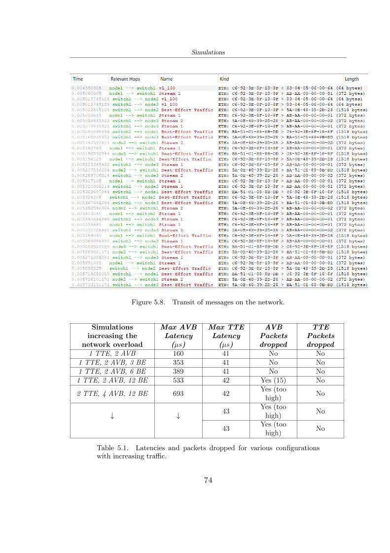
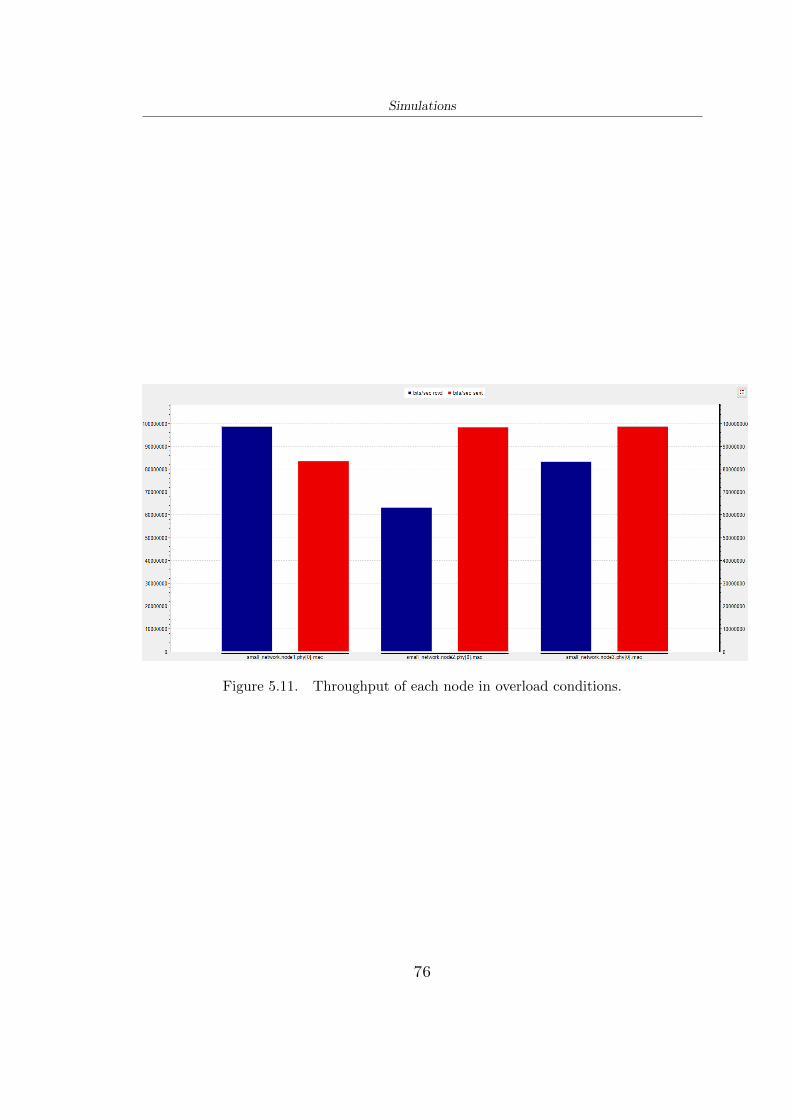
ferent Cross Traffic frame size. . . . . . . . . . . . . . . . . . . . . . 755.10 Throughput of each node in regular conditions (no overload). . . . . 755.11 Throughput of each node in overload conditions. . . . . . . . . . . . 76
ix
Chapter 1
Introduction and motivations
This chapter describes the context of network architectures in the automotive fieldwith its functional domains, the purpose of the thesis and consequently the reasonsfor using Automotive Ethernet.
1.1 Context
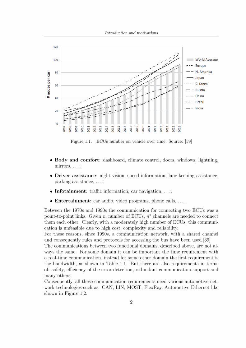
From the late 1800s until the 1970s the cars were entities purely mechanical orhydraulic. Since the 1970s, there has been an exponential increment of electronicparts inside a vehicle. Firstly, the electronic part played a small role, mostly forbattery charging, starter, ignition and illumination. A few years later, the growinguse of reliable and inexpensive electronic components and the widespread use ofsoftware replaced many mechanical parts. In fact, the first electronic control units(ECUs) were born with the main purpose of assisting the driver to control thevehicle, thanks to: antilock braking system (ABS), electric power steering (EPS),electronic stability program (ESP), engine control, lights control, doors control,windows control and many other functions.Each new function in a vehicle is implemented with an ECU made of a microcon-troller, many sensors and actuators. Nowadays the electronic part is dominating onthe mechanical part, more than 70-100 ECUs, as shown in Figure 1.1, are embed-ded inside a vehicle. All of this to guarantee lower emission, longer range, highersafety and some comfort functions.[39]Typically, the ECUs are classified into functional domains due to the different re-quirements and constraints: [2]
❼ Powertrain: real-time and safety control. The communication is for control-ling the engine automatic transmission, hybrid control, transmission,gearbox, . . . ;
❼ Chassis: real-time and safety control. The communication is for controllingstability and dynamics, such as steering, braking, suspension, . . . ;
1
Introduction and motivations
Figure 1.1. ECUs number on vehicle over time. Source: [59]
❼ Body and comfort: dashboard, climate control, doors, windows, lightning,mirrors, . . . ;
❼ Driver assistance: night vision, speed information, lane keeping assistance,parking assistance, . . . ;
❼ Infotainment: traffic information, car navigation, . . . ;
❼ Entertainment: car audio, video programs, phone calls, . . . .
Between the 1970s and 1990s the communication for connecting two ECUs was apoint-to-point links. Given n, number of ECUs, n2 channels are needed to connectthem each other. Clearly, with a moderately high number of ECUs, this communi-cation is unfeasible due to high cost, complexity and reliability.For these reasons, since 1990s, a communication network, with a shared channeland consequently rules and protocols for accessing the bus have been used.[39]The communications between two functional domains, described above, are not al-ways the same. For some domain it can be important the time requirement witha real-time communication, instead for some other domain the first requirement isthe bandwidth, as shown in Table 1.1. But there are also requirements in termsof: safety, efficiency of the error detection, redundant communication support andmany others.Consequently, all these communication requirements need various automotive net-work technologies such as: CAN, LIN, MOST, FlexRay, Automotive Ethernet likeshown in Figure 1.2.
Driver Assistance and Driver Safety < 250us or < 1ms depending on the system 20 - 100Mbps per cameraHuman-Machine Interface < 10ms Varies by system, but high
Table 1.1. Domain time requirements
Figure 1.2. Domain centric architecture with different network technolo-gies for each vehicle segment.
In particular, as it will deepen in the following chapters, Automotive Ethernet needsa hierarchical domain network architecture with Ethernet Switches like shown inFigure 1.3.All these network technologies are not ideal, but each is proper for each differentapplication, however they will be analysed in the next chapters, with particularemphasis on Automotive Ethernet.
1.2 Motivations and thesis scope
The large use of electronic components ECUs, actuators and sensors installed invehicles, infotainment systems, driver assistance systems and so on have enormouslyincreased the bandwidth usage for data transmission which cannot be satisfied by
3
Introduction and motivations
Figure 1.3. Domain distributed in a future network. Source: [24]
existing in-vehicle network, like CAN, FlexRay, MOST.Ethernet deployment will satisfy the bandwidth problem and will reduce the costin terms of electronics, cablings, network interfaces and onboard computing power.So, the objective is to guarantee high bandwidth requirements, small latency, goodsynchronization and network management requirements with a flexible and scalablenetwork technology.Unfortunately, Ethernet can not be used as it is, for example as in local networks,because: [27]
❼ It does not meet requirements on EMI (Electromagnetic Interference), RFI(Radio-Frequency Interference) and stringent temperatures;
❼ It can not synchronize the time between different devices;
❼ It can not be possible to transmit data shared by multiple types of sources (nocontrol of bandwidth for different streams);
❼ It can not guarantee a pre-defined latency less than the order of microseconds.
Thanks to a worldwide partnership AUTOSAR (Automotive Open System Archi-tecture), a non-profit alliance of automotive industry providers OPEN Alliance(One-pair-Ethernet Alliance) and many other research centers, the Ethernet stan-dards have been adapted, integrated and modified for the automotive field.However, Automotive Ethernet needs to be tested in order to avoid late discovery ofproblems, so conformance testing, interoperability testing and protocol validationare needed to validate the network technology.The testing process has to be reliable and compatible with automotive V-Cycles,
4
Introduction and motivations
Figure 1.4. V-cycle software development process. Source: [3]
Figure 1.4, for all the development phase and for all components.The goal of this thesis is to analyse and deepen the Ethernet network in automotivefield and define methodologies and strategies to test and develop ECUs intercon-nected with Automotive Ethernet for all the seven layers of the Open SystemsInterconnection model (OSI model), shown in Figure 1.5. Finally to understandhow Automotive Ethernet stack and the related real-time protocols (i.e. AVB andTTEthernet) work, a simulation environment and an open-source framework willbe studied.
5
Introduction and motivations
Figure 1.5. Open Systems Interconnection layers (OSI model), protocolstack of Automotive Ethernet.
1.3 Thesis outline
This thesis is organized in the following chapters:Chapter 2 will describe, briefly, the usual automotive networks: CAN, LIN, MOSTand FlexRay that are important to understand Automotive Ethernet.Chapter 3 will introduce, firstly, Ethernet used in local networks, then the rele-vant subject to this thesis: Automotive Ethernet with differences and integrationseach other. It will be explained the influence of Ethernet in automotive field, allthe OSI model layers, from physical to application layer, in detail, with the mainApplication-related Protocols.Chapter 4 will contain methodologies and strategies to test and validate confor-mances and performances for ECUs on Automotive Ethernet networks accordingto AUTOSAR, OPEN Alliance, Avnu Alliance and other research groups.In Chapter 5 will be presented an introduction to the simulation environments(OMNeT++, INET framework, CoRE4INET) and an example of Automotive Eth-ernet simulation with 3 nodes and 1 switch that communicate different types oftraffic (AVB and TTE).Finally, Chapter 6 summarises the work with an outline of the results and proposesfurther works related to Automotive Ethernet, ECU testing and simulations.
6
Chapter 2
Conventional automotive networks
This chapter describes, briefly, the traditional automotive networks, such as: CAN,LIN, MOST and FlexRay that are important to understand Automotive Ethernet.
2.1 CAN
One of the first network technologies inside a vehicle was the Controller Area Net-work (CAN) developed by Robert Bosch GmbH in 1980. Today CAN bus is themost widely used network technology in vehicles.Usually, on average, data rate of a CAN bus is between 125 Kbit/s and 500 Kbit/s,it depends how many nodes are connected. It is used, in particular, for powertrain,chassis and body domain for its robustness and bounded delays.CAN is implemented as a shared bus with each node (see Figure 2.1), in fact twoor more nodes can not communicate at the same time without a collision. Conse-quently, to avoid collisions, an arbitrage mechanism, Media Access Control (MAC),is needed. CAN uses Non-Return-to-Zero (NRZ) bit representation with a 5 bit asstuffing. [40]The bus network is modelled like a logic AND with “1” recessive bit and “0” dom-inant bit. When all nodes, simultaneously, transmit a message with content 1, thebus will remain at 1. Instead, when one of the nodes transmits 0, the bus will be setto 0, allowing the node that sent 0 to continue sending the message, interruptingthe transmission of all other nodes.So the collisions are solved by a priority-based communication where lowest mes-sage identifier, contained in the header field of the frames, has highest priority.CAN uses unshielded twisted pair (UTP) of copper wires where one cable is calledCAN High, the other one CAN Low. The signal between two cables has a voltageof 2.5V; when a 0 dominant bit appears, CAN High voltage increases the nominalvalue by 1V, instead CAN Low voltage decreases, the nominal value by 1V; whena logic 1 it appears both CAN High and CAN Low have 2.5V. [4]
7
Conventional automotive networks
Figure 2.1. CAN bus.
A standard CAN data frame, which contains up to 8 bytes of data, is shown inFigure 2.2 where:
Figure 2.2. CAN data frame.
❼ SOF: Underline the start of frame transmission;
❼ Arbitration: first 11 bits are the Identifier ID which sets the priority of dataframe, as explained before, lowest ID means highest priority. The 12th bit isthe Remote Transmission Request equal to 0 for data frame;
❼ Control: this field contain the Payload length on four bits and more two bitsfor the protocol;
❼ Payload: Data;
❼ CRC: used to check the transmission, as explained shortly after;
❼ Ack: acknowledgment for CRC field;
❼ EOF: seven recessive bits to end the frame.
CAN also owns many error detections like:
8
Conventional automotive networks
❼ Comparison of CRC field between frame transmitted and received frame;
❼ Error counters (Transmit Error Counter TEC and Receive Error CounterREC) modified when a frame is correctly received or it contains an error.
When an error is detected by a CAN node, a particular error frame is sent to everyother node connected to CAN network.[40]
2.1.1 CAN-FD
Particular attention is needed to CAN-FD, the last version of CAN network, withFlexible Data Rate. In this case the payload increases from 8 bytes of CAN to 64bytes. This reduces overload and it increases efficiency.CAN-FD is used for data rates from 2 to 5 Mbps, that data rate is reached becausearbitration is not useful during some part of a frame. (See Figure 2.3).
Figure 2.3. Arbitration field comparison between CAN and CAN-FD. Source: [66]
This last version shares the same functionalities of classic CAN. Instead, inside aframe, there is three new control bits: Extended Data Length (EDL), Bit RateSwitch (BRS), Error State Indicator (ESI). CRC field uses also more check bits toreduce the risk of undetected errors.For completeness, there is a most recent CAN version, which is CAN XL with10Mbps as data rate, but it has not yet been fully developed. [4] [35]
2.2 LIN
For some applications, such as windows, mirrors, seats, air conditioning control andmany others, CAN technology is too expensive and provides too much protectionfor these applications that do not require safety and speed. So, in the late 1990sthe LIN Consortium, a set of companies (Volkswagen, BMW, Volvo and Daimler),developed the Local Interconnect Network (LIN) with a first version released inNovember 2002. [40]LIN was designed with 1-wire unshielded with a data rate limited to 20 Kbit/s, it
9
Conventional automotive networks
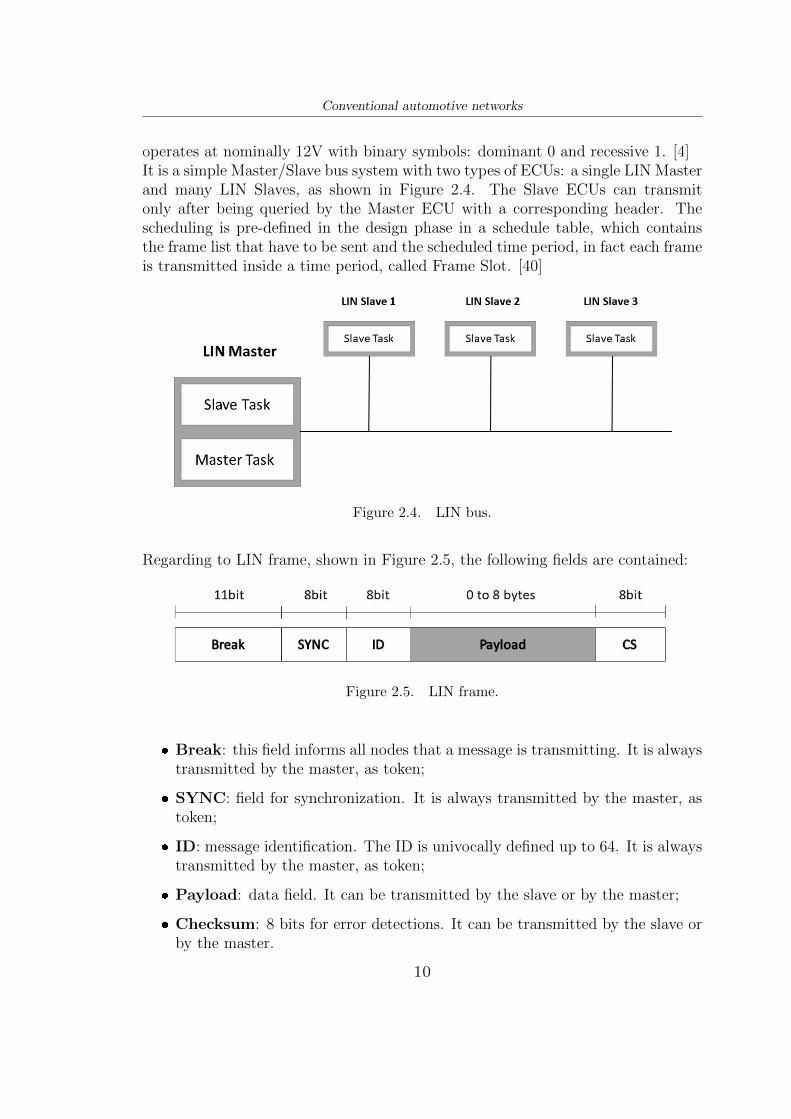
operates at nominally 12V with binary symbols: dominant 0 and recessive 1. [4]It is a simple Master/Slave bus system with two types of ECUs: a single LIN Masterand many LIN Slaves, as shown in Figure 2.4. The Slave ECUs can transmitonly after being queried by the Master ECU with a corresponding header. Thescheduling is pre-defined in the design phase in a schedule table, which containsthe frame list that have to be sent and the scheduled time period, in fact each frameis transmitted inside a time period, called Frame Slot. [40]
Figure 2.4. LIN bus.
Regarding to LIN frame, shown in Figure 2.5, the following fields are contained:
Figure 2.5. LIN frame.
❼ Break: this field informs all nodes that a message is transmitting. It is alwaystransmitted by the master, as token;
❼ SYNC: field for synchronization. It is always transmitted by the master, astoken;
❼ ID: message identification. The ID is univocally defined up to 64. It is alwaystransmitted by the master, as token;
❼ Payload: data field. It can be transmitted by the slave or by the master;
❼ Checksum: 8 bits for error detections. It can be transmitted by the slave orby the master.
10
Conventional automotive networks
2.3 MOST
Around the 2000s, with the advent of first navigation systems, complex audio sys-tems, Bluetooth, advanced displays, the data traffic is increased. Companies likeBMW, Harman/Becker and SMSC formed the MOST Cooperation, developing theMedia Oriented Serial Transport (MOST) technology. [67]MOST has been developed for optimizing the transport of audio-video data becauseCAN and LIN networks can not guarantee high bandwidth for that purpose. Inparticular MOST150, the last MOST technology, can reach 150 Mb/s, supportingEthernet Packet Channel with Internet Protocol (IP) functionalities.MOST relies on all layers of OSI model. As physical layer, it usually runs on plasticoptical fiber (POF) cable to avoid electromagnetic compatibility problems and toguarantee electrical isolation. However, MOST150 can support also coaxial cable.Both physical layers have advantages in terms of bandwidth, but they are too ex-pensive. In fact, this reason and many other, shown later, led to a rapid decreasein the use of MOST technology.Since this technology is synchronous based on Time Division Multiple Access (TDMA),all nodes have the same clock to avoid collisions.MOST uses ring topology, as shown in Figure 2.6, with one ECU which worksas timing master, allowing the synchronization, through synchronization messages,with all the other ECUs. Master ECU starts unidirectional communication withthe next node, the latter will transmit the frame to next node, until it reaches therecipient. [4]
Figure 2.6. MOST ring topology.
In Figure 2.7 is shown a MOST150 frame with four main fields:
11
Conventional automotive networks
Figure 2.7. MOST150 frame.
❼ Control Channel: used for controlling network operations;
❼ SYNC Channel: used to exchange audio-video in a synchronous manner.(Analog and digital audio-video);
❼ ASYNC Channel: used to transmit packages asynchronously. (Internettraffic and information from the navigation system);
❼ MOST Ethernet Packets: introduced in MOST150 for IP data.
2.4 FlexRay
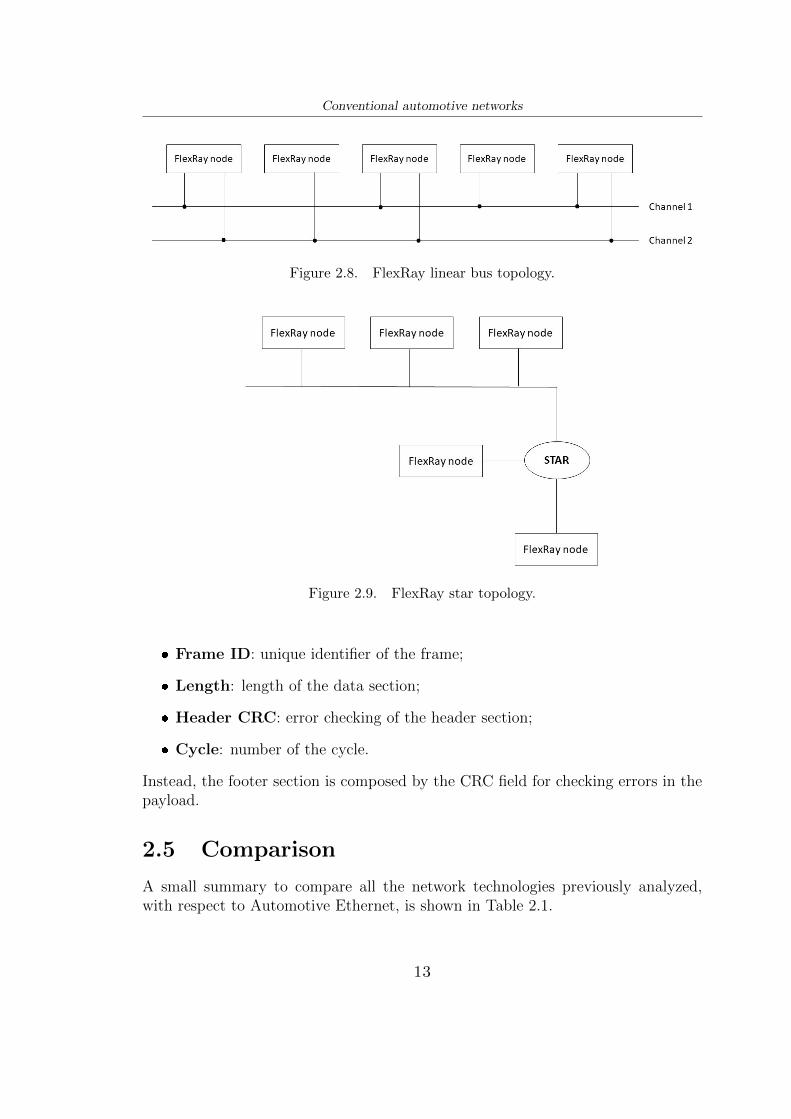
In the 2000s a consortium of major companies (BMW, Bosch, Daimler and manyothers) developed FlexRay protocol. The goal was to develop a time-triggeredcommunication standard for safety-critical and time-critical automotive applica-tions like all X-by-Wire systems (e.g. brake-by-wire, steer-by-wire and so on),powertrain and chassis controls.As shown later there are many advantages and disadvantages in FlexRay, but manycompanies have stopped or are stopping using it, shifting their focus to AutomotiveEthernet.The technology is based on cycles, which are a combination of two types of win-dows: time-triggered (static) and event triggered (dynamic). The first one uses aTime Domain Multiple Access (TDMA) protocol, where there are many identicalslots divided in time. If a node does not have to transmit, a null frame is sent, sothat something is always received. [35]The second one uses Flexible Time Division Multiple Access (FTDMA), where timeis divided in sub-slots and each station can initiate communication within its sub-slot.Regarding to the topology this network is very flexible, it can be used: linear bus,active and passive stars and point to point, as shown in Figure 2.8 and Figure 2.9.Topology can be also redundant using dual channels. [40] [67]A FlexRay frame format, shown in Figure 2.10, consists in three parts: header,payload and footer section. In the header part there are:
❼ Status Bit: it represents the start of the frame which can be null frame, syncframe, startup frame;
12
Conventional automotive networks
Figure 2.8. FlexRay linear bus topology.
Figure 2.9. FlexRay star topology.
❼ Frame ID: unique identifier of the frame;
❼ Length: length of the data section;
❼ Header CRC: error checking of the header section;
❼ Cycle: number of the cycle.
Instead, the footer section is composed by the CRC field for checking errors in thepayload.
2.5 Comparison
A small summary to compare all the network technologies previously analyzed,with respect to Automotive Ethernet, is shown in Table 2.1.
13
Conventional automotive networks
Figure 2.10. FlexRay frame.
Technology Advantages Disadvantages
CAN
- Low cost;- Robustness, safe, reliable;- Error capabilities: error counters, CRCfields;- Flexibility: CAN bus is multi-master,there is no need to add special purposenode (like switches), so a new node canbe easily added or removed [4];- Simulators and tools simple to use.
- Reduced data rates: between 125Kbit/sand 5-10Mb/s for CAN-FD and CAN-XL;- Low efficiency: very low payload 8 bytefor classic CAN, 64 bytes for CAN-FD,consequently high overhead.
LIN- The lowest cost of all network technolo-gies;- Easy to implement.
- Reduced data rates: up to 20 Kbit/s;- The messages are scheduled in time.Consequently, the master can not startimmediately a communication;- Low error detection capabilities.
MOST
- Very high bandwidth (150 Mbit/s) re-spect to CAN, LIN;- Immunity to electromagnetic compati-bility problems.
- Too expensive due to optic fiber andcoaxial cable;- Low flexibility;- Silicones for MOST are only developedby one company.
FlexRay- Dual redundant channels;- Flexible in topologies.
- Bandwidth of only 20 Mbit/s;- No protocol support for infotainment;- Complicated to implement.
AutomotiveEthernet
- Very high data rate: 10Mbps to 10Gbps;- Robustness: differential signal, smartmodulation and filtering;- Flexibility in topologies;- Many protocols, standards and applica-tions;- Reductions in vehicle weight and cost.
- Cost of new technology higher than amore mature one (it will settle down),plus the cost of switches;- Adding flexibility means adding cost forswitches;- Test tools are not so obvious. They willbe analysed in a future chapter.
Table 2.1. Network technologies comparison.
14
Chapter 3
Automotive Ethernet
This chapter introduces, firstly, Ethernet used in local area networks, then therelevant subject to this thesis: Automotive Ethernet with the differences and inte-grations each other. It will be explained the influence of Ethernet in the automotivefield, all the OSI model layers, from physical to application layer, with the maindedicated Application Protocols.
3.1 Standard Ethernet
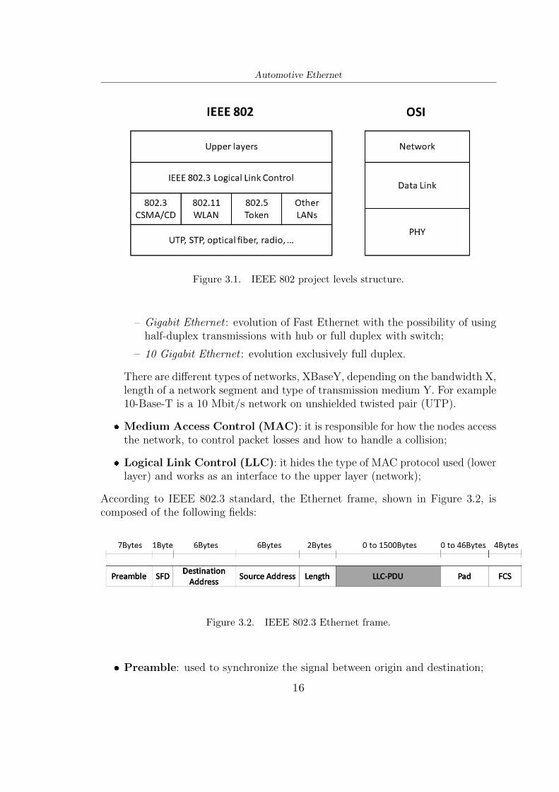
Ethernet network, the most used Local Area Network (LAN) in the word, wasdeveloped in the early 70’s by Xerox PARC which needed a connection betweencomputer, internet and printer. Xerox opened the technology to everyone, conse-quently, in 1983, the 802.3 Project, inside the Institute of Electrical and ElectronicsEngineers (IEEE), was created. Over the years IEEE 802.3 added, and continuesto add, new Ethernet Standards. The IEEE 802 project structure defines threelayers, as shown in Figure 3.1: [48]
❼ Physical Layer (PL):
– 10 Mbit/s Ethernet : it uses the Carrier Sense Multiple Access with Colli-sion Detection (CSMA/CD)1 protocol;
– Fast Ethernet : evolution of the previous generation. It uses a full-duplextransfer and a star center (switch) configuration. In fact, each receivedframe is retransmitted only to the recipient line and not to all;
1CSMA/CD: protocol that allows to detect any collisions in the network. Carrier sense listensto the channel before transmitting, if it detects no signals it transmits. Collision detection checksfor collisions during transmission. If a collision is detected the transmission is interrupted and isdelayed after a random time established by a backoff algorithm.
15
Automotive Ethernet
Figure 3.1. IEEE 802 project levels structure.
– Gigabit Ethernet : evolution of Fast Ethernet with the possibility of usinghalf-duplex transmissions with hub or full duplex with switch;
– 10 Gigabit Ethernet : evolution exclusively full duplex.
There are different types of networks, XBaseY, depending on the bandwidth X,length of a network segment and type of transmission medium Y. For example10-Base-T is a 10 Mbit/s network on unshielded twisted pair (UTP).
❼ Medium Access Control (MAC): it is responsible for how the nodes accessthe network, to control packet losses and how to handle a collision;
❼ Logical Link Control (LLC): it hides the type of MAC protocol used (lowerlayer) and works as an interface to the upper layer (network);
According to IEEE 802.3 standard, the Ethernet frame, shown in Figure 3.2, iscomposed of the following fields:
Figure 3.2. IEEE 802.3 Ethernet frame.
❼ Preamble: used to synchronize the signal between origin and destination;
16
Automotive Ethernet
❼ Start of Frame Delimiter: it is a 10101011 sequence which indicates thestart of frame;
❼ Destination and Source Address: indicate address of the recipient andsender station respectively;
❼ Length: length of the next field;
❼ LLC-PDU: payload of the transmitted data;
❼ Pad: it guarantees a minimum length;
❼ Frame Check Sequence: it contains the Cyclic Redundancy Check (CRC)to check errors.
3.2 From Standard Ethernet to Automotive Eth-ernet
As anticipated in the introduction, IEEE 802.3 Ethernet was born to guarantee veryhigh speed, but as it was, it could not guarantee strictly requirements in terms of la-tency, jitter, congestion, guaranteed bandwidth and message arrivals, consequentlyit could not be used for real-time or multimedia applications. Moreover traditionalEthernet is too noisy and it has too interference for automotive applications.For these reasons, the automotive industry has taken some parts of IEEE 802.3Ethernet and changed others. For weight and cost reasons the 4-pair single direc-tion cable is substituted by a single pair bi-directional UTP cable for both transmitand receive. Mainly the changes are in the physical layer using, as it will be seen,the Broadcom BroadR-Reach technology, promoted by OPEN Alliance, which per-mits full-duplex communication, ideally doubling the throughput, unlike CAN, LIN,Most, FlexRay.[4] Main differences are shown in Table 3.1.Besides data link and physical layers also other layers have to be taken into account,from network layer to application layer.The first vehicle with Automotive Ethernet was released in 2008 by the BMWGroup for diagnostic purposes. Later in 2013 the new BroadR-Reach 100Base-T1physical layer was used in BMW’s X5.For this purpose, in time, three Automotive Ethernet use cases (generations) canbe considered: [13]
❼ First generation ⇒ Diagnostics Over IP (DoIP): used to synchronize thesignal between origin and destination;
❼ Second generation ⇒ ADAS and Infotainment : for camera systems andinfotainment applications;
17
Automotive Ethernet
Ethernet100Base-TX(IEEE
802.3)
AutomotiveEthernet
100Base-T1(IEEE802.3bw)
AutomotiveEthernet
1000Base-T1(IEEE802.3bp)
Data Rate 100 Mbps 100 Mbps 1000 MbpsSignal MLT3 PAM3 at 66.667 Mb/s PAM3 at 750 Mb/s
Modulation 4B/5B 4B/3B, 3B/2T 80B/81BLength 100m 15m 15m
Connector RJ45Depends on themanufacturer
Depends on themanufacturer
CableTwo twisted pairs
single directionOne twisted pair
bi-directionalOne twisted pair
bi-directional
Table 3.1. Main differences between Ethernet and Automotive Ethernet. [32]
❼ Third generation ⇒ Ethernet Network Backbone: communication betweenECUs in a hierarchical way as a scalable solution with different data rate.
Consequently, new protocols for different use cases (generations) have been devel-oped, as shown in Figure 3.3.
Figure 3.3. Protocols for different use cases (generations) of AutomotiveEthernet. Source: [27]
In the following sections, according to OSI model, will be covered in detail:
18
Automotive Ethernet
– Physical layer technologies for 10 Mbps, 100 Mbps and 1 Gbps;
To overcome the bandwidth issue, in these years, many Ethernet standards havebeen developed. In this section they will be analysed with emphasis on differentdata rates: 10 Mbps, 100 Mbps and 1 Gbps. In Figure 3.4 is shown a time horizonof the various standards.
Figure 3.4. Time horizon of Automotive Ethernet Standards.
3.3.1 100 Mbps and 1000 Mbps networking technologies
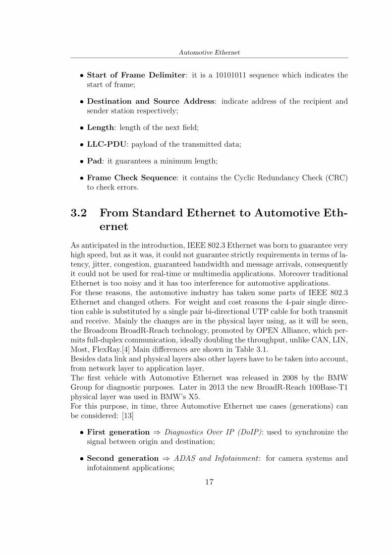
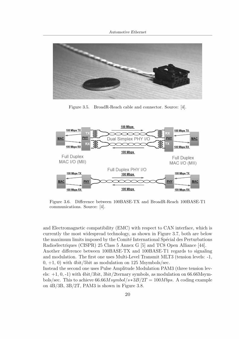
100BASE-T1 The most used Fast Ethernet standard for local area networks,100BASE-TX, is based over two pairs of unshielded twisted pairs (UTPs). Onepair is used for transmission and the other one for reception, establishing a 100Mbps full-duplex communication. Instead, 100BASE-T1, born as BroadR-Reachand standardized by IEEE as 802.3bw, provides well established limits on EMC,EMI, temperature-grade and uses a single UTP cable, as shown in Figure 3.5, forbidirectional signal (meaning low cost and low cabling weight).Differences between the two communication methods are shown in Figure 3.6.Respect to 100BASE-TX (standard Ethernet cable), BroadR-Reach cable can achieve80% cost reduction and 30% weight reduction according to Open Alliance andBroadcom publications. For these reasons 100BASE-T1 has taken over, particu-larly in the automotive field. As it will be seen 100BASE-T1 can also supportcommunication of audio/video using AVB/TSN standard, it can support differentdata types with many priorities.Comparing the requirements of 100BASE-T1 on Electromagnetic Interference (EMI)
19
Automotive Ethernet
Figure 3.5. BroadR-Reach cable and connector. Source: [4].
Figure 3.6. Difference between 100BASE-TX and BroadR-Reach 100BASE-T1communications. Source: [4].
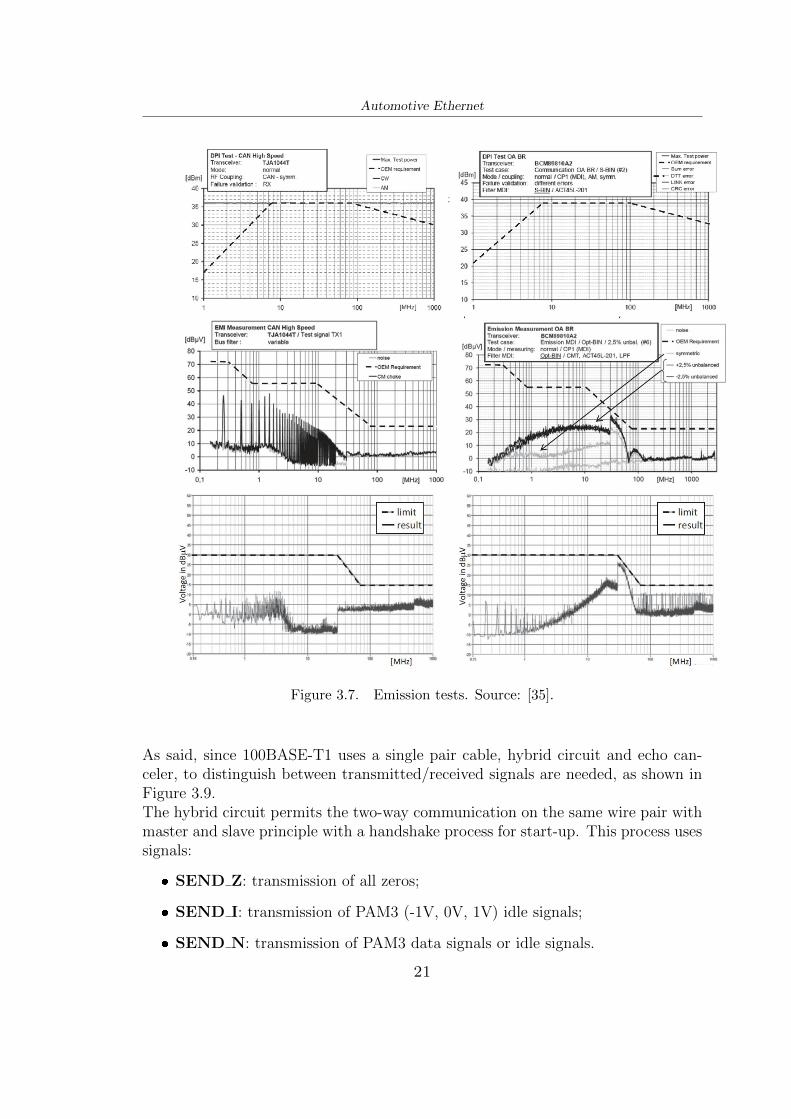
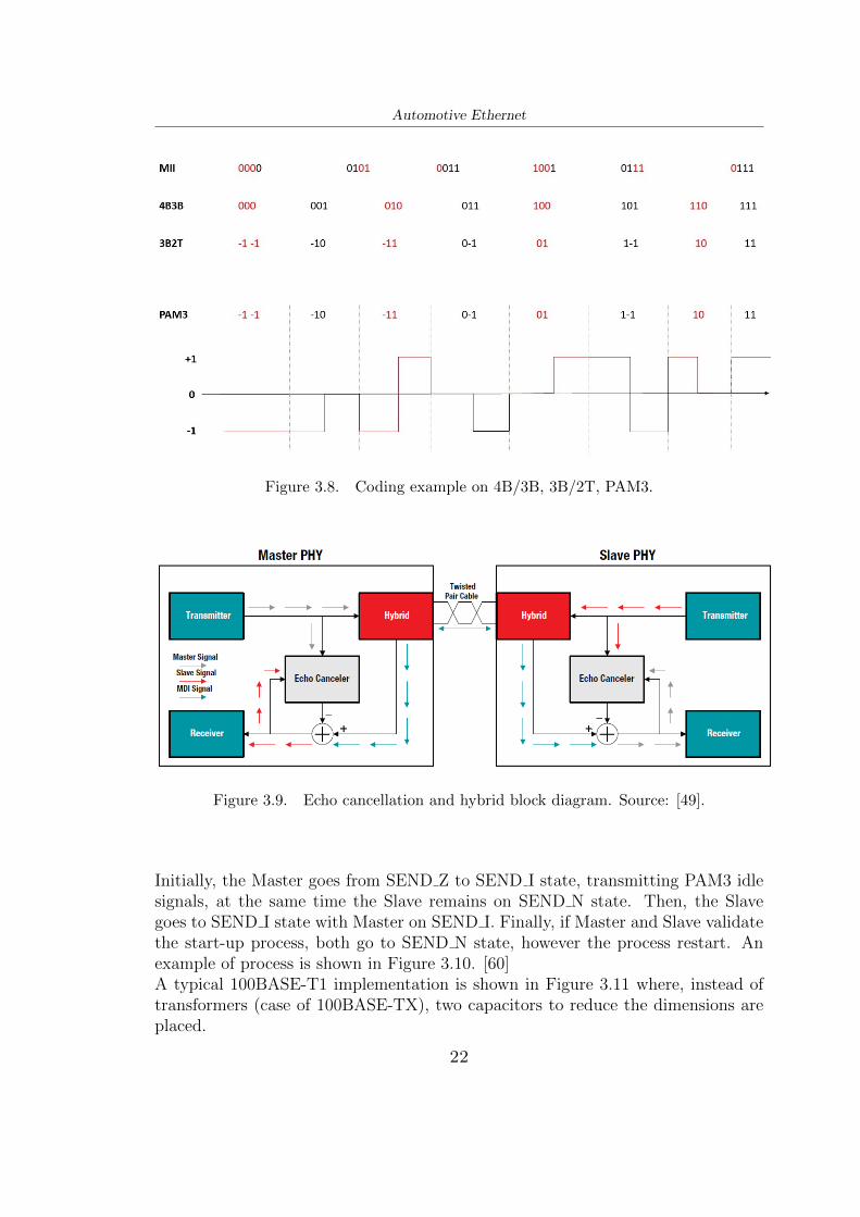
and Electromagnetic compatibility (EMC) with respect to CAN interface, which iscurrently the most widespread technology, as shown in Figure 3.7, both are belowthe maximum limits imposed by the Comite International Special des PerturbationsRadioelectriques (CISPR) 25 Class 5 Annex G [5] and TC8 Open Alliance [44].Another difference between 100BASE-TX and 100BASE-T1 regards to signalingand modulation. The first one uses Multi-Level Transmit MLT3 (tension levels: -1,0, +1, 0) with 4bit/5bit as modulation on 125 Msymbols/sec.Instead the second one uses Pulse Amplitude Modulation PAM3 (three tension lev-els: +1, 0, -1) with 4bit/3bit, 3bit/2ternary symbols, as modulation on 66.66Msym-bols/sec. This to achieve 66.66Msymbol/s∗3B/2T = 100Mbps. A coding exampleon 4B/3B, 3B/2T, PAM3 is shown in Figure 3.8.
20
Automotive Ethernet
Figure 3.7. Emission tests. Source: [35].
As said, since 100BASE-T1 uses a single pair cable, hybrid circuit and echo can-celer, to distinguish between transmitted/received signals are needed, as shown inFigure 3.9.The hybrid circuit permits the two-way communication on the same wire pair withmaster and slave principle with a handshake process for start-up. This process usessignals:
❼ SEND N: transmission of PAM3 data signals or idle signals.
21
Automotive Ethernet
Figure 3.8. Coding example on 4B/3B, 3B/2T, PAM3.
Figure 3.9. Echo cancellation and hybrid block diagram. Source: [49].
Initially, the Master goes from SEND Z to SEND I state, transmitting PAM3 idlesignals, at the same time the Slave remains on SEND N state. Then, the Slavegoes to SEND I state with Master on SEND I. Finally, if Master and Slave validatethe start-up process, both go to SEND N state, however the process restart. Anexample of process is shown in Figure 3.10. [60]A typical 100BASE-T1 implementation is shown in Figure 3.11 where, instead oftransformers (case of 100BASE-TX), two capacitors to reduce the dimensions areplaced.
22
Automotive Ethernet
Figure 3.10. Link startup process: Master (yellow, pink) and Slave (blue, green).Switch between SEND Z, SEND I, SEND N. Source: [60].
Regarding to the 100BASE-T1 frame, is practically the same as IEEE 802.3 stan-dard Ethernet, shown in Section 3.1, with Start of Stream Delimiter (SSD) at thebeginning and END of Stream Delimiter (ESD) at the end of frame. [60]
1000BASE-T1 The bandwidth increasing, the birth of autonomous driving, theuse of many sensors and the need for redundancy, during the years, led to switchto a 1Gbps technology such as 1000BASE-T1 standardized by IEEE 802.3bp.1000BASE-T1 uses Pulse Amplitude Modulation PAM3 (three tension levels: +1, 0,-1) with 3bit/2ternary symbols as modulation on 750Msymbols/sec, this to achieve
23
Automotive Ethernet
750Msymbol/s ∗ 3B/2T = 1000Mbps.
3.3.2 10 Mbps networking technology
10BASE-T1S With the advent of new sensors applications and ECU develop-ments, a 10Mbps Ethernet PHY was born that can be used for:
❼ ECUs that require faster communication than CAN-FD, but lower then 100Mbpsof 100BASE-T1 for cost and energy reasons;
❼ Simple, redundant sensors and actuators network (only 1 connector at ECUper bus line like shown in Figure 3.12);
❼ As a replacement for legacy networks such as FlexRay.
Figure 3.12. Sensor network example on 10BASE-T1S.
In particular IEEE 802.3cg defines PHY 10BASE-T1S, a low-complexity pair, where“S” means short length of 15-25m (there is another PHY 10BASE-T1L for longdistance, 1km, but not useful for automotive applications).10BASE-T1S is on single twisted pair and uses 4B5B encoding, its peculiarity isthat it supports three different operating modes: [72]
❼ Point-to-point 15m with optional full duplex;
❼ Point-to-point 15m with mandatory half duplex;
❼ 25m optional half duplex multidrop, it supports bus architectures (like CAN),using Physical Layer Collision Avoidance PLCA (a CSMA/CD extension) toimprove performance in stress condition.
Full duplex and multidrop options are in mutually exclusive.As said the principal reason for using 10BASE-T1S is the cost, due to the mul-tidrop topology and a simplified PHY design. In case of a multidrop topology onlyone PHY per end node ECU is used, instead of two for traditional Ethernet, lessconnectors and switches. This saves (N − 2)/(2N − 2) PHYs with N number of
24
Automotive Ethernet
Figure 3.13. Difference between traditional switched Ethernet and10BASE-T1S as multidrop topology.
nodes. [35] The difference is shown in Figure 3.13.In Figure 3.14 cost and data rate are compared with the target that will be reached.
Figure 3.14. Comparison between cost and data rate of differenttechnologies. Source: [14]
25
Automotive Ethernet
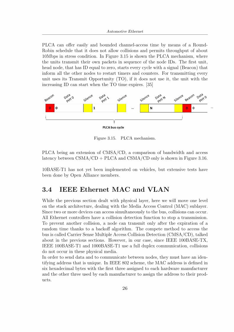
PLCA can offer easily and bounded channel-access time by means of a Round-Robin schedule that it does not allow collisions and permits throughput of about10Mbps in stress condition. In Figure 3.15 is shown the PLCA mechanism, wherethe units transmit their own packets in sequence of the node IDs. The first unit,head node, that has ID equal to zero, starts every cycle with a signal (Beacon) thatinform all the other nodes to restart timers and counters. For transmitting everyunit uses its Transmit Opportunity (TO), if it does not use it, the unit with theincreasing ID can start when the TO time expires. [35]
Figure 3.15. PLCA mechanism.
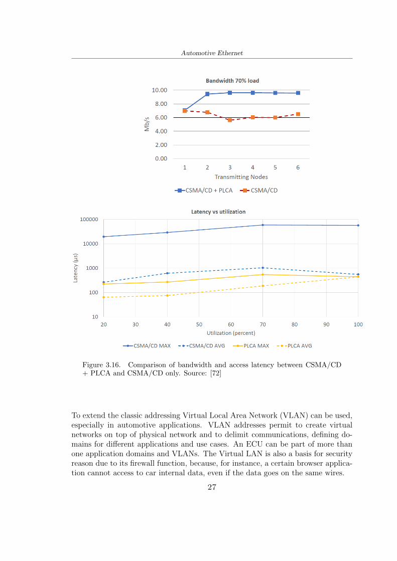
PLCA being an extension of CMSA/CD, a comparison of bandwidth and accesslatency between CSMA/CD + PLCA and CSMA/CD only is shown in Figure 3.16.
10BASE-T1 has not yet been implemented on vehicles, but extensive tests havebeen done by Open Alliance members.
3.4 IEEE Ethernet MAC and VLAN
While the previous section dealt with physical layer, here we will move one levelon the stack architecture, dealing with the Media Access Control (MAC) sublayer.Since two or more devices can access simultaneously to the bus, collisions can occur.All Ethernet controllers have a collision detection function to stop a transmission.To prevent another collision, a node can transmit only after the expiration of arandom time thanks to a backoff algorithm. The compete method to access thebus is called Carrier Sense Multiple Access Collision Detection (CMSA/CD), talkedabout in the previous sections. However, in our case, since IEEE 100BASE-TX,IEEE 100BASE-T1 and 1000BASE-T1 use a full duplex communication, collisionsdo not occur in these physical media.In order to send data and to communicate between nodes, they must have an iden-tifying address that is unique. In IEEE 802 scheme, the MAC address is defined insix hexadecimal bytes with the first three assigned to each hardware manufacturerand the other three used by each manufacturer to assign the address to their prod-ucts.
26
Automotive Ethernet
Figure 3.16. Comparison of bandwidth and access latency between CSMA/CD+ PLCA and CSMA/CD only. Source: [72]
To extend the classic addressing Virtual Local Area Network (VLAN) can be used,especially in automotive applications. VLAN addresses permit to create virtualnetworks on top of physical network and to delimit communications, defining do-mains for different applications and use cases. An ECU can be part of more thanone application domains and VLANs. The Virtual LAN is also a basis for securityreason due to its firewall function, because, for instance, a certain browser applica-tion cannot access to car internal data, even if the data goes on the same wires.
27
Automotive Ethernet
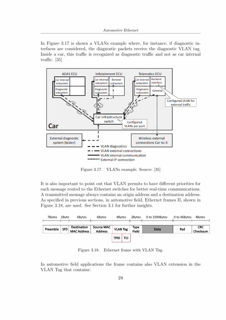
In Figure 3.17 is shown a VLANs example where, for instance, if diagnostic in-terfaces are considered, the diagnostic packets receive the diagnostic VLAN tag.Inside a car, this traffic is recognized as diagnostic traffic and not as car internaltraffic. [35]
Figure 3.17. VLANs example. Source: [35]
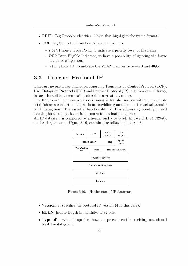
It is also important to point out that VLAN permits to have different priorities foreach message routed to the Ethernet switches for better real-time communications.A transmitted message always contains an origin address and a destination address.As specified in previous sections, in automotive field, Ethernet frames II, shown inFigure 3.18, are used. See Section 3.1 for further insights.
Figure 3.18. Ethernet frame with VLAN Tag.
In automotive field applications the frame contains also VLAN extension in theVLAN Tag that contains:
28
Automotive Ethernet
❼ TPID: Tag Protocol identifier, 2 byte that highlights the frame format;
❼ TCI: Tag Control information, 2byte divided into:
– PCP : Priority Code Point, to indicate a priority level of the frame;
– DEI : Drop Eligible Indicator, to have a possibility of ignoring the framein case of congestion;
– VEI : VLAN ID, to indicate the VLAN number between 0 and 4096.
3.5 Internet Protocol IP
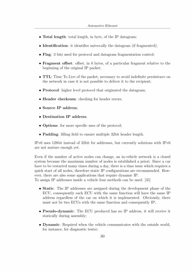
There are no particular differences regarding Transmission Control Protocol (TCP),User Datagram Protocol (UDP) and Internet Protocol (IP) in automotive industry,in fact the ability to reuse all protocols is a great advantage.The IP protocol provides a network message transfer service without previouslyestablishing a connection and without providing guarantees on the actual transferof IP datagrams. The essential functionality of IP is addressing, identifying andlocating hosts and packages from source to destination address.An IP datagram is composed by a header and a payload. In case of IPv4 (32bit),the header, shown in Figure 3.19, contains the following fields: [48]
Figure 3.19. Header part of IP datagram.
❼ Version: it specifies the protocol IP version (4 in this case);
❼ HLEN: header length in multiples of 32 bits;
❼ Type of service: it specifies how and precedence the receiving host shouldtreat the datagram;
29
Automotive Ethernet
❼ Total length: total length, in byte, of the IP datagram;
❼ Identification: it identifies univocally the datagram (if fragmented);
❼ Flag: 3 bits used for protocol and datagram fragmentation control;
❼ Fragment offset: offset, in 8 bytes, of a particular fragment relative to thebeginning of the original IP packet;
❼ TTL: Time To Live of the packet, necessary to avoid indefinite persistence onthe network in case it is not possible to deliver it to the recipient;
❼ Protocol: higher level protocol that originated the datagram;
❼ Header checksum: checking for header errors;
❼ Source IP address;
❼ Destination IP address;
❼ Options: for more specific uses of the protocol;
❼ Padding: filling field to ensure multiple 32bit header length.
IPv6 uses 128bit instead of 32bit for addresses, but currently solutions with IPv6are not mature enough yet.
Even if the number of active nodes can change, an in-vehicle network is a closedsystem because the maximum number of nodes is established a priori. Since a carhave to be restarted many times during a day, there is a time issue which requires aquick start of all nodes, therefore static IP configurations are recommended. How-ever, there are also some applications that require dynamic IP.To assign IP addresses inside a vehicle four methods can be used: [35]
❼ Static: The IP addresses are assigned during the development phase of theECU, consequently each ECU with the same function will have the same IPaddress regardless of the car on which it is implemented. Obviously, theremust not be two ECUs with the same function and consequently IP;
❼ Pseudo-dynamic: The ECU produced has no IP address, it will receive itstatically during assembly;
❼ Dynamic: Required when the vehicle communicates with the outside world,for instance, for diagnostic tester;
30
Automotive Ethernet
❼ Multiple: A single ECU uses many IP addresses, for instance, for diagnosticpurposes where if the address was single, it had to be changed every timeit was connected with external world. An example is shown in Figure 3.20where the dynamic IP addresses y and z are assigned only when the Externaldiagnostic system (tester) is connected with dynamic IP address x.
Figure 3.20. Example of multiple IP addressing. Source: [35]
The switches of OSI layer two, using MAC addresses have lower latency and can onlybe implemented on hardware, compared to a more complex, larger and expensivein software, router of OSI layer three. Consequently, currently dedicated routerchips for the automotive field are not available, contrary to switches. [35]
3.6 TCP/UDP
At transport layer the main protocols used are Transmission Control Protocol(TCP) and User Datagram Protocol (UDP). The first one is connection-oriented
31
Automotive Ethernet
and the second one is connectionless. Both protocols carry segments, called Trans-port Protocol Data Units (TPDU). Since the lower IP layer carries units of variousapplications, ports, acting as an interface between the applications and the IP layer,are defined. Port number and IP address make up a socket.
UDP protocol The objective of User Datagram Protocol (UDP) is to multiplexmore information flows on a single UDP flow, checking for errors only at the nodes.The transfer is connectionless, so out of sequence deliveries can happen and there isno connection establishment. It is also not possible to perform segment loss checks,as they are not numbered.However, having connectionless transmission results in faster transmission thanTCP protocol. It is also possible to send segments in Multicast or Broadcast mode.A header of an UDP segment is shown in Figure 3.21, where the following fieldsappear: [48]
Figure 3.21. Header of UDP segment.
❼ Source port;
❼ Destination port;
❼ Length: in bytes of the entire UDP segment;
❼ Checksum: error detection for the UDP segment.
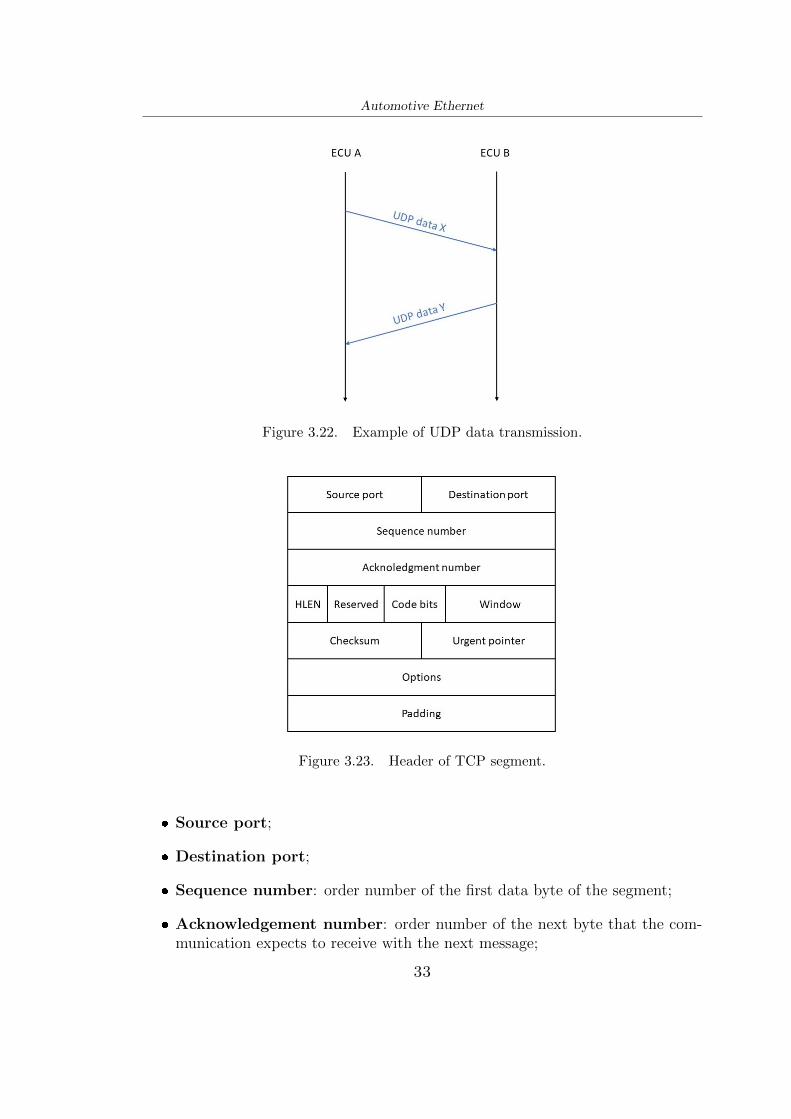
An example for data transmission between two ECUs, in UDP protocol, is shownin Figure 3.22 where it is possible to see that acknowledgments are not generated.
TCP protocol The objective of Transmission Control Protocol (TCP) is toimprove the underlying connectionless IP protocol service by providing a reli-able connection-oriented service, multiplexing multiple streams into a single TCPstream.In contrast to UDP, in case of loss, duplication or out of sequence deliveries seg-ments, the TCP protocol reconstructs the flow thanks to an appropriate numberingof the segments. In this case Broadcast or Multicast mode are not possible to use,because the connection must be between two ECUs.A header of an TCP segment, which proves its reliability, is shown in Figure 3.23where the following fields are used: [48]
32
Automotive Ethernet
Figure 3.22. Example of UDP data transmission.
Figure 3.23. Header of TCP segment.
❼ Source port;
❼ Destination port;
❼ Sequence number: order number of the first data byte of the segment;
❼ Acknowledgement number: order number of the next byte that the com-munication expects to receive with the next message;
33
Automotive Ethernet
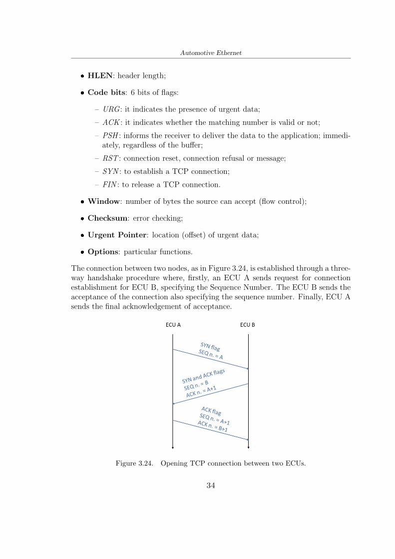
❼ HLEN: header length;
❼ Code bits: 6 bits of flags:
– URG : it indicates the presence of urgent data;
– ACK : it indicates whether the matching number is valid or not;
– PSH : informs the receiver to deliver the data to the application; immedi-ately, regardless of the buffer;
– RST : connection reset, connection refusal or message;
– SYN : to establish a TCP connection;
– FIN : to release a TCP connection.
❼ Window: number of bytes the source can accept (flow control);
❼ Checksum: error checking;
❼ Urgent Pointer: location (offset) of urgent data;
❼ Options: particular functions.
The connection between two nodes, as in Figure 3.24, is established through a three-way handshake procedure where, firstly, an ECU A sends request for connectionestablishment for ECU B, specifying the Sequence Number. The ECU B sends theacceptance of the connection also specifying the sequence number. Finally, ECU Asends the final acknowledgement of acceptance.
Figure 3.24. Opening TCP connection between two ECUs.
34
Automotive Ethernet
Regarding to data transmission of TCP segments, an example is shown in Figure3.25. The ECU A sends the data X to ECU B, this answers with an acknowledg-ment and data Y. Finally ECU A acknowledges data Y.
Figure 3.25. TCP data transmission.
At the end, the connection is closed, as in figure 3.26, where the ECU A sendsthe request with flag FIN, the ECU B acknowledges. Then also ECU B sends therequest with flag FIN and also ECU A acknowledges.
35
Automotive Ethernet
Figure 3.26. Closing TCP connection between two ECUs.
3.7 Application Protocols
In this subsection will be described the most used application-related protocol inautomotive field, such as: SOME/IP, AVB/TSN, TTEthernet and DoIP.
3.7.1 SOME/IP
Scalable service-Oriented MiddlewarE over IP (SOME/IP) was designed by BMWgroup in 2011 and it was implemented in series production cars at BMW in 2014.From version 4.1 of AUTOSAR it has become an integral part of it providing scal-ability, flexibility and adaptability. However, in addition to AUTOSAR, it shall beimplemented on different operating system like OSEK and even embedded deviceswithout operating system.SOME/IP works as middleware, like shown in Figure 3.27, in the sense that makesthe network transparent to the software exchanging data, doing as an intermediarybetween different applications. The message communications and function callsbetween software are implemented just once to better test the modules.SOME/IP allows applications to communicate providing service-oriented commu-nication over a network, in this way the sender sends his message only when atleast one recipient has requested it so that the network does not have to processuseless data. On the contrary, in a signal-oriented transmission the data is sent by
36
Automotive Ethernet
Figure 3.27. SOME/IP middleware. Source [9].
the sender when values are updated regardless of the need of the receiver.SOME/IP is defined on client-server architecture, there are several communicationmethods between client and server: [35][9]
❼ Request and Response: the client sends a request for calling a function;the server replies with the result of the function;
❼ Fire and Forget: the client sends a request for calling a function, but theserver does not reply;
❼ Event service: the client subscribes for a service, then the service sends pe-riodically, or when there is a change, information. (Similar to CAN network);
❼ Field service: with getter and setter methods fields can be read or modified.When a field is changed, a notification is sent.
The four communication methods, which rely on UDP and TCP sockets, are shownin Figure 3.28. To determine if a service is available or not SOME/IP-SD (Service
Figure 3.28. SOME/IP communication methods: Request and Response,Fire and Forget, Events, Fields.
37
Automotive Ethernet
Discovery) is used. Especially in start-up phase of the car, Service Discover isvery useful for simplifying, reducing the time, since each ECU can communicate itsavailability. At the same time it is also useful for detecting undetected ECUs thatfail and for saving energy by supplying it only to ECUs that need it.Due to its short initialization time, SOME/IP is suitable for ADAS and infotain-ment systems, but it cannot be used for strictly real time applications yet, such asmotor control.SOME/IP and SOME/IP-SD headers are shown in Figure 3.29. The fields ofSOME/IP header mean: [1]
Figure 3.29. SOME/IP and SOME/IP-SD headers.
❼ Message ID: used to identify the Remote Procedure Call to a method of anapplication or to identify an event;
❼ Length: from the next header field to the end of the payload;
❼ Request ID: to differentiate between multiple calls of the same method;
❼ Protocol Version: SOME/IP version;
❼ Interface Version: Major Version of the Service Interface;
❼ Message Type: used to differentiate different types of messages (e.g. RE-QUEST, REQUEST NO RETURN, RESPONSE, ERROR, ...);
38
Automotive Ethernet
❼ Return Code: to signal to report whether a request has been successfullyprocessed.
SOME/IP uses a decentralized approach where each ECU offers and requests avail-ability to all other ECUs in broadcast mode.
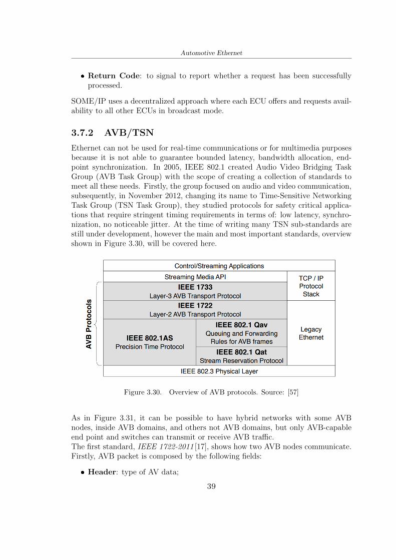
3.7.2 AVB/TSN
Ethernet can not be used for real-time communications or for multimedia purposesbecause it is not able to guarantee bounded latency, bandwidth allocation, end-point synchronization. In 2005, IEEE 802.1 created Audio Video Bridging TaskGroup (AVB Task Group) with the scope of creating a collection of standards tomeet all these needs. Firstly, the group focused on audio and video communication,subsequently, in November 2012, changing its name to Time-Sensitive NetworkingTask Group (TSN Task Group), they studied protocols for safety critical applica-tions that require stringent timing requirements in terms of: low latency, synchro-nization, no noticeable jitter. At the time of writing many TSN sub-standards arestill under development, however the main and most important standards, overviewshown in Figure 3.30, will be covered here.
Figure 3.30. Overview of AVB protocols. Source: [57]
As in Figure 3.31, it can be possible to have hybrid networks with some AVBnodes, inside AVB domains, and others not AVB domains, but only AVB-capableend point and switches can transmit or receive AVB traffic.The first standard, IEEE 1722-2011 [17], shows how two AVB nodes communicate.Firstly, AVB packet is composed by the following fields:
❼ Header: type of AV data;
39
Automotive Ethernet
Figure 3.31. Hybrid network with AVB domain and not. Source: [36]
❼ Stream ID: specific data stream derived from MAC address of Talker;
❼ Presentation Time: maximum time when a packet must be received at theListener;
❼ Payload Information: format of the payload;
❼ Payload.
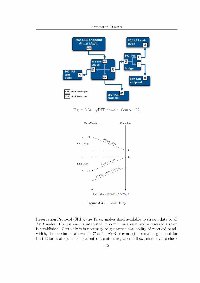
A packet, shown in Figure 3.32, lies on the first two layers and not on higher layersof OSI model to reduce the processing time and consequently latency. The AVBcommunication works between talker, source of data, and listener, consumer of datalike shown in 3.33. In IEEE 1722-2016 [19] version more data types are supported.[35]Synchronization between talker and listener nodes is described in IEEE 802.1AS-2011 [18] standard with the generalized Precision Time Protocol (gPTP). A node,the Grandmaster, provides all other nodes a synchronization clock as commonreference global time with an accuracy of better than 1µs and precision of somenanoseconds. This node is chosen, dynamically, among those that have the bestclock in the AVB network thanks to the Best Master Clock selection Algorithm
40
Automotive Ethernet
Figure 3.32. IEEE 1722 streaming data packet.
Figure 3.33. AVB topology: Talker and Listener.
(BMCA) where the clock of each node is cyclically checked with the current grand-master and eventually replaced with the best one. The algorithm also deals withthe so called Clock Spanning tree, contains all the paths between AVB nodes, sothat the whole network knows the propagation delays (Link Delay) of the differentpaths. In Figure 3.34 is shown a gPTP domain with a grandmaster. The LinkDelay is computed:
(T4− T1)− (T3− T2)
2
as shown in Figure 3.35. Then this delay will be used for clock synchronizationbetween master and slave exchanging Sync and Follow up packets as in Figure3.36. Typically, the node locations and the link lengths do not change between carignitions, so delay values are fixed and saved.[35] Since in 2011 version a change ofGrandmaster takes too time (more than 200ms) by BMCA algorithm, with a newstandard version: IEEE 802.1AS-2020 [23], redundant Grandmasters, redundantClock Spanning trees and multiple gPTP are implemented.To allocate bandwidth for each application, thanks to IEEE 802.1Qat [16] Stream
41
Automotive Ethernet
Figure 3.34. gPTP domain. Source: [37]
Figure 3.35. Link delay.
Reservation Protocol (SRP), the Talker makes itself available to stream data to allAVB nodes. If a Listener is interested, it communicates it and a reserved streamis established. Certainly it is necessary to guarantee availability of reserved band-width, the maximum allowed is 75% for AVB streams (the remaining is used forBest-Effort traffic). This distributed architecture, where all switches have to check
42
Automotive Ethernet
Figure 3.36. Sync and Follow up packets.
individually if the bandwidth is available, is time consuming. So IEEE 802.1Qcc[22]specifies a more advanced SRP as centralized network management.Regarding to traffic, it is possible to define Class A streams (highest priority) andClass B streams or its own user-defined class, as shown in Table 3.2.[35]
Traffic Class Transmission Period Expected Latency (7 hops)Class A 125µs 2msClass B 250µs 50ms
Table 3.2. Priority classes.
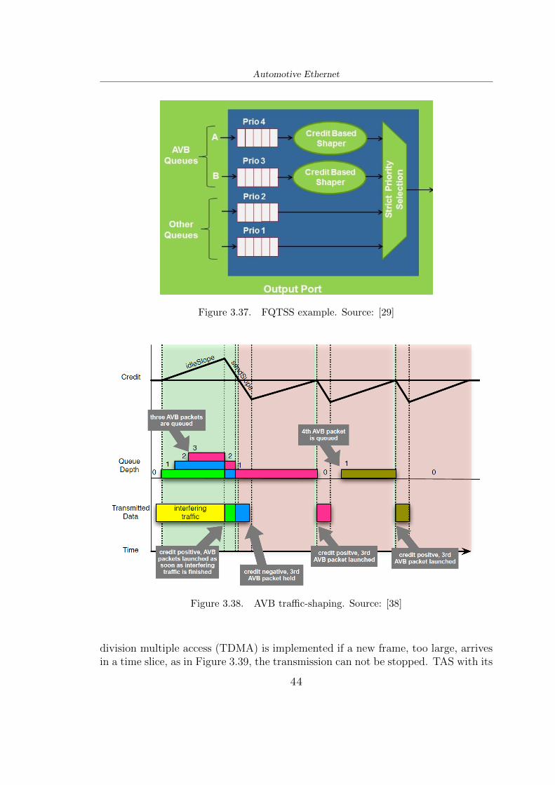
IEEE 802.1Qav [15] manages the allocation priority of streams. The Forwardingand Queuing of Time Sensitive Streams (FQTSS) standard takes care of creatingmessage queues and then forwarding them according to the order of priority, split-ting between time-critical and non-time-critical traffic, and applying the Credit-Based Shaper (CBS) to avoid traffic overloads and to not block the bus in presenceof low priority data as shown in Figure 3.37. Since high jitter provides low qual-ity communication with frame jumps, it is possible to have continuous streams,more uniform, thanks to CBS. In Figure 3.38 an example of AVB traffic shaping isshown: when the credit is greater than or equal to zero the AVB-Queue can startits transmission, in such case the credit will have a negative fixed slope; insteadwhen a frame is waiting in queue the credit will have a positive fixed slope; in caseof empty queue the credit is equal to zero. [12]The scheduling of packets transmission between stations and switches is standard-ized in IEEE 802.1Qbv [21], thanks to Time Aware Shaping (TAS). Since time
43
Automotive Ethernet
Figure 3.37. FQTSS example. Source: [29]
Figure 3.38. AVB traffic-shaping. Source: [38]
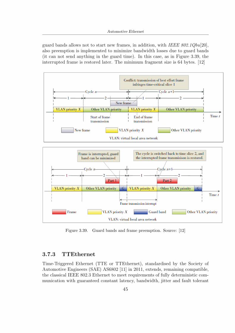
division multiple access (TDMA) is implemented if a new frame, too large, arrivesin a time slice, as in Figure 3.39, the transmission can not be stopped. TAS with its
44
Automotive Ethernet
guard bands allows not to start new frames, in addition, with IEEE 802.1Qbu[20],also preemption is implemented to minimize bandwidth losses due to guard bands(it can not send anything in the guard time). In this case, as in Figure 3.39, theinterrupted frame is restored later. The minimum fragment size is 64 bytes. [12]
Figure 3.39. Guard bands and frame preemption. Source: [12]
3.7.3 TTEthernet
Time-Triggered Ethernet (TTE or TTEthernet), standardised by the Society ofAutomotive Engineers (SAE) AS6802 [11] in 2011, extends, remaining compatible,the classical IEEE 802.3 Ethernet to meet requirements of fully deterministic com-munication with guaranteed constant latency, bandwidth, jitter and fault tolerant
45
Automotive Ethernet
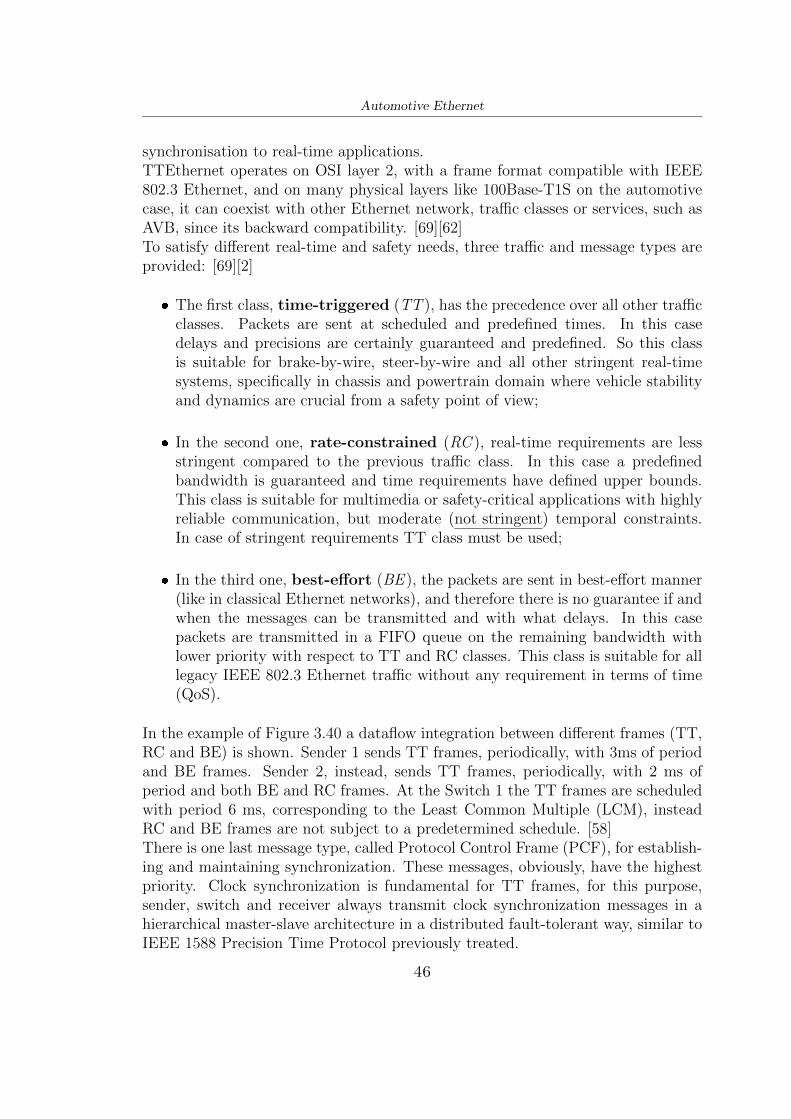
synchronisation to real-time applications.TTEthernet operates on OSI layer 2, with a frame format compatible with IEEE802.3 Ethernet, and on many physical layers like 100Base-T1S on the automotivecase, it can coexist with other Ethernet network, traffic classes or services, such asAVB, since its backward compatibility. [69][62]To satisfy different real-time and safety needs, three traffic and message types areprovided: [69][2]
❼ The first class, time-triggered (TT ), has the precedence over all other trafficclasses. Packets are sent at scheduled and predefined times. In this casedelays and precisions are certainly guaranteed and predefined. So this classis suitable for brake-by-wire, steer-by-wire and all other stringent real-timesystems, specifically in chassis and powertrain domain where vehicle stabilityand dynamics are crucial from a safety point of view;
❼ In the second one, rate-constrained (RC ), real-time requirements are lessstringent compared to the previous traffic class. In this case a predefinedbandwidth is guaranteed and time requirements have defined upper bounds.This class is suitable for multimedia or safety-critical applications with highlyreliable communication, but moderate (not stringent) temporal constraints.In case of stringent requirements TT class must be used;
❼ In the third one, best-effort (BE ), the packets are sent in best-effort manner(like in classical Ethernet networks), and therefore there is no guarantee if andwhen the messages can be transmitted and with what delays. In this casepackets are transmitted in a FIFO queue on the remaining bandwidth withlower priority with respect to TT and RC classes. This class is suitable for alllegacy IEEE 802.3 Ethernet traffic without any requirement in terms of time(QoS).
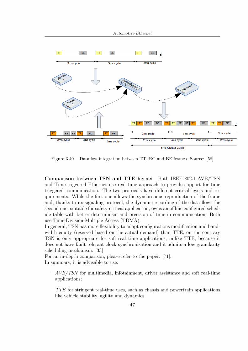
In the example of Figure 3.40 a dataflow integration between different frames (TT,RC and BE) is shown. Sender 1 sends TT frames, periodically, with 3ms of periodand BE frames. Sender 2, instead, sends TT frames, periodically, with 2 ms ofperiod and both BE and RC frames. At the Switch 1 the TT frames are scheduledwith period 6 ms, corresponding to the Least Common Multiple (LCM), insteadRC and BE frames are not subject to a predetermined schedule. [58]There is one last message type, called Protocol Control Frame (PCF), for establish-ing and maintaining synchronization. These messages, obviously, have the highestpriority. Clock synchronization is fundamental for TT frames, for this purpose,sender, switch and receiver always transmit clock synchronization messages in ahierarchical master-slave architecture in a distributed fault-tolerant way, similar toIEEE 1588 Precision Time Protocol previously treated.
46
Automotive Ethernet
Figure 3.40. Dataflow integration between TT, RC and BE frames. Source: [58]
Comparison between TSN and TTEthernet Both IEEE 802.1 AVB/TSNand Time-triggered Ethernet use real time approach to provide support for timetriggered communication. The two protocols have different critical levels and re-quirements. While the first one allows the synchronous reproduction of the frameand, thanks to its signaling protocol, the dynamic recording of the data flow; thesecond one, suitable for safety-critical application, owns an offline configured sched-ule table with better determinism and precision of time in communication. Bothuse Time-Division-Multiple Access (TDMA).In general, TSN has more flexibility to adapt configurations modification and band-width equity (reserved based on the actual demand) than TTE, on the contraryTSN is only appropriate for soft-real time applications, unlike TTE, because itdoes not have fault-tolerant clock synchronization and it admits a low-granularityscheduling mechanism. [33]For an in-depth comparison, please refer to the paper: [71].In summary, it is advisable to use:
– AVB/TSN for multimedia, infotainment, driver assistance and soft real-timeapplications;
– TTE for stringent real-time uses, such as chassis and powertrain applicationslike vehicle stability, agility and dynamics.
47
Automotive Ethernet
3.7.4 DoIP
Diagnostics over IP (DoIP), standardized on ISO 13400 [25], has had an importantimpact in diagnostic area of Automotive Ethernet enabling communication betweenECUs and an external tester using IP, TCP and UDP protocols, this to identifyand resolve faults, flashing ECUs. AUTOSAR is the software architecture forimplementing the communication between ECUs and the external tester. [30]Instead of Unified Diagnostic Services (UDS) on CAN, that support max datarated of 500kbps, DoIP supports data rates up to 100Mbps, so it is suitable for allapplications that require fast data transfer.DoIP supports on-board and off-board communications. The first one warns thepassengers by activating on-board warning, the second one instead stores the faultto be retrieved, subsequently, only in a garage by a mechanic.An example of vehicle network architecture is shown in Figure 3.41, where a DoIPGateway is needed to save the effort and cost of integrating DoIP stack in everyECU separately.
As shown in Figure 3.42, in the communication sequence, the diagnostic testerenables the sending of Diagnostic Request, then the recipient ECU process thisrequest and reply with an acknowledge at the tester. In this process the DoIPGateway works as intermediary, forwarding requests and responses to the respectiveECUs and testers. A DoIP message is shown in Figure 3.43.
48
Automotive Ethernet
Figure 3.42. Communication sequence. Source: [52]
Figure 3.43. DoIP message.
49
Chapter 4
ECUs on Automotive Ethernet:
testing and validation
This chapter describes, according to many automotive companies with its whitepapers, existing methodologies and strategies for testing and validating intercon-nected ECUs on Automotive Ethernet.
4.1 Testing and Validation
As mentioned previously in Section 1.2 Automotive Ethernet needs to be tested,the goal is to avoid late discovery of problems, for safety reason, but also to savemoney and time, in fact it is important not only to find an error, but to find itas soon as possible, according to the automotive V-Cycles, in Figure 1.4, for allthe development phase and for all components. It must also be said that testingthe TCP/IP stack is much more complex than other protocols such as CAN orFlexRay, however it must be done to increase the quality, reliability and safety ofthe vehicle. To augment the re-use, quality and reduce the cost, testing has to beunder standardization. So OPEN Alliance created standardized tests for its Techni-cal Committee number 8 (TC8) for IPv4, ARP, DHCP, ICMP, IPv4 AUTOCONF,UDP, TCP and SOME/IP.Following the V-Cycle model on testing and validation phase, firstly, component-level testing has to be done to evaluate an ECU as a separate entity with respectto the other ECU, but with accessible communications data. Then, network-leveltesting to evaluate all communication functions and consequently system-level test-ing to examine all the requirement specifications with all ECUs connected. Finallyin-vehicle acceptance test and maintenance to also solve the cases of error code inmalfunctions. [35]As explained in previous sections Automotive Ethernet, which is often used forsafety-critical systems, only has new PHY layers, but everything behind it is pretty
50
ECUs on Automotive Ethernet: testing and validation
much taken from standard Ethernet with related testing methodologies. Howeverthere are new protocols and applications which are to be tested. Since the au-tomotive field, with Automotive Ethernet, has different requirements than localnetworks, with standard Ethernet, it is good to start testing the network from ev-erything that is already well established for the IT industry. [55]According to many white papers [55][27][70] tests can be divided into three majortypes:
– Conformance and interoperability testing: studies if a device under test(DUT) works in conformance with the requirements;
– Negative testing: studies the response to the system when there are errorsor unexpected signals;
In particular, at component level, OPEN Alliance has made available AutomotiveEthernet ECU Test Specification regarding conformance and interoperability test-ing [44]. Instead performance testing is usually done according to the InternetEngineering Task Force (IETF) Request for Comments (RFC) 2544, called Bench-marking Methodology for Network Interconnect Devices [51]. In addition, sinceAutomotive Ethernet uses layer 2 switches, RFC 2889 is used to test them [28].
4.2 Conformance Testing
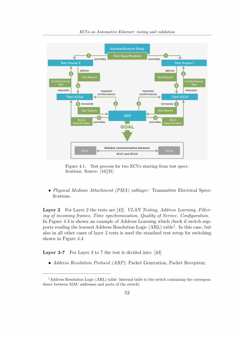
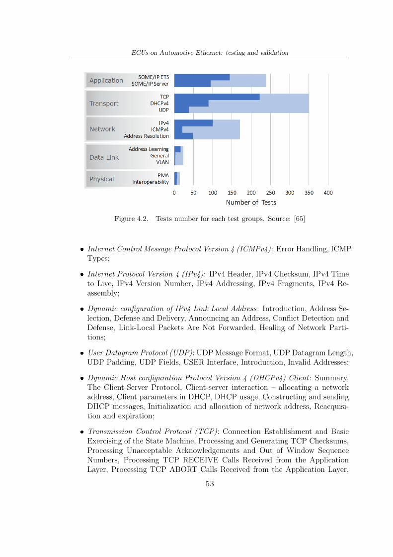
In IT industry, nowadays, all protocols are well standardized and tested, so the com-pliance and interoperability testing phases are shortened. For the automotive field,on the other hand, it is quite the opposite, because Automotive Ethernet is stillnew and under development. Consequently, OPEN Alliance has made availableAutomotive Ethernet ECU Test Specification (TC8) [44] regarding conformanceand interoperability testing. In this Test Specifications is checked if a device undertest (DUT) works in conformance with the requirements. Open Alliance also sug-gests the test process, in Figure 4.1, to have a reliable communication between twoECUs starting from the test specifications.From 2020 the Open Alliance test specifications are divided respecting the OSI levelarchitecture: Layer 1 [41], Layer 2 [42] and from Layer 3 to 7 [43]. In general, alarge number of tests for the protocol layers in Figure 4.2, are carried out for eachfunction in an automated way.
Layer 1 For Layer 1, referred to 100Base-T1, tests are divided into:[41]
❼ Interoperability : Link-up time, Signal Quality, Cable diagnostics;
51
ECUs on Automotive Ethernet: testing and validation
Figure 4.1. Test process for two ECUs starting from test speci-fications. Source: [44][31]
❼ Physical Medium Attachment (PMA) sublayer : Transmitter Electrical Speci-fications.
Layer 2 For Layer 2 the tests are [42]: VLAN Testing, Address Learning, Filter-ing of incoming frames, Time synchronization, Quality of Service, Configuration.In Figure 4.3 is shown an example of Address Learning which check if switch sup-ports reading the learned Address Resolution Logic (ARL) table1. In this case, butalso in all other cases of layer 2 tests is used the standard test setup for switchingshown in Figure 4.4.
Layer 3-7 For Layer 3 to 7 the test is divided into: [43]
1Address Resolution Logic (ARL) table: Internal table to the switch containing the correspon-dence between MAC addresses and ports of the switch)
52
ECUs on Automotive Ethernet: testing and validation
Figure 4.2. Tests number for each test groups. Source: [65]
❼ Internet Control Message Protocol Version 4 (ICMPv4): Error Handling, ICMPTypes;
❼ Internet Protocol Version 4 (IPv4): IPv4 Header, IPv4 Checksum, IPv4 Timeto Live, IPv4 Version Number, IPv4 Addressing, IPv4 Fragments, IPv4 Re-assembly;
❼ Dynamic configuration of IPv4 Link Local Address : Introduction, Address Se-lection, Defense and Delivery, Announcing an Address, Conflict Detection andDefense, Link-Local Packets Are Not Forwarded, Healing of Network Parti-tions;
❼ User Datagram Protocol (UDP): UDP Message Format, UDP Datagram Length,UDP Padding, UDP Fields, USER Interface, Introduction, Invalid Addresses;
❼ Dynamic Host configuration Protocol Version 4 (DHCPv4) Client : Summary,The Client-Server Protocol, Client-server interaction – allocating a networkaddress, Client parameters in DHCP, DHCP usage, Constructing and sendingDHCP messages, Initialization and allocation of network address, Reacquisi-tion and expiration;
❼ Transmission Control Protocol (TCP): Connection Establishment and BasicExercising of the State Machine, Processing and Generating TCP Checksums,Processing Unacceptable Acknowledgements and Out of Window SequenceNumbers, Processing TCP RECEIVE Calls Received from the ApplicationLayer, Processing TCP ABORT Calls Received from the Application Layer,
53
ECUs on Automotive Ethernet: testing and validation
TCP Packet Flag Generation in Response to Receiving Invalid Packets, Pro-cessing TCP Flags, Closing a TCP Connection, Processing of TCP MSS, Endof Option List, and NO-Operation Options, Processing Out of Order Segmentsand Delayed ACKs, Retransmission Timeout, Generation of Zero WindowProbes, Nagle Algorithm, Use of the Urgent Pointer, Connection Establish-ment, Header, Sequence Number, Acknowledgment, Control Flags;
❼ Scalable service-Oriented MiddlewarE over IP Protocol (SOME/IP): MessageFormat, Service Discovery Messages, Service Discovery Communication Be-haviour, Some/IP Basic Functionality, Specification of the SOME/IP on-wireformat, Remote Procedure Call Protocol (RPC) specification, Enhanced Testa-bility Service test cases.
In Figure 4.5 is shown an example of IPv4 Header test case which check if DUTgenerates an IPv4 Packet with a Total Length greater than or equal to 20. In thiscase, but also in most other cases of layers 3-7 tests is used the test setup shown inFigure 4.6.All these tests are subdivided in many subtests. Open Alliance test solutions,obviously, work at component-level. Regarding network-level tests and validations,
54
ECUs on Automotive Ethernet: testing and validation
Figure 4.4. Layer 2 Standard test setup for switching. Source: [42]
currently, Open Alliance does not provide anything due to the high complexity andvariety of configurations and architectures. Thus there are no general specifications,but individual test solutions are required. [63]
4.3 Performance Testing
As said in IT context Ethernet is well standardized and there are many performancetesting methodologies available. Since Automotive Ethernet is quite similar tostandard Ethernet, except for PHY layers and some new protocols, it is good tostart testing the new networks from everything that is already well known from theIT world, i.e. RFC 2544 and RFC 2889. [53]
4.3.1 RFC 2544
Although with different requirements, more stringent in the automotive field, totest the performance of a network the following parameters are usually considered:
❼ Throughput: amount of data transmitted between two points, measured inbits or packets per second;
❼ Latency: time taken by the data to reach one point to another;
❼ Frame loss: packets lost to reach the destination;
55
ECUs on Automotive Ethernet: testing and validation
Figure 4.5. Layers 3-7 test, called: ”IPv4 HEADER 01: Ensure thatthe DUT generates an IPv4 Packet with a Total Length greater thanor equal to 20”. Source: [43]
❼ Back-to-back Frames: number of frames in the longest burst of frames, atthe highest throughput, the node can support without frame loss.
In 1999 Internet Engineering Task Force (IETF) created the Request for Comments(RFC) 2544, called Benchmarking Methodology for Network Interconnect Devices
56
ECUs on Automotive Ethernet: testing and validation
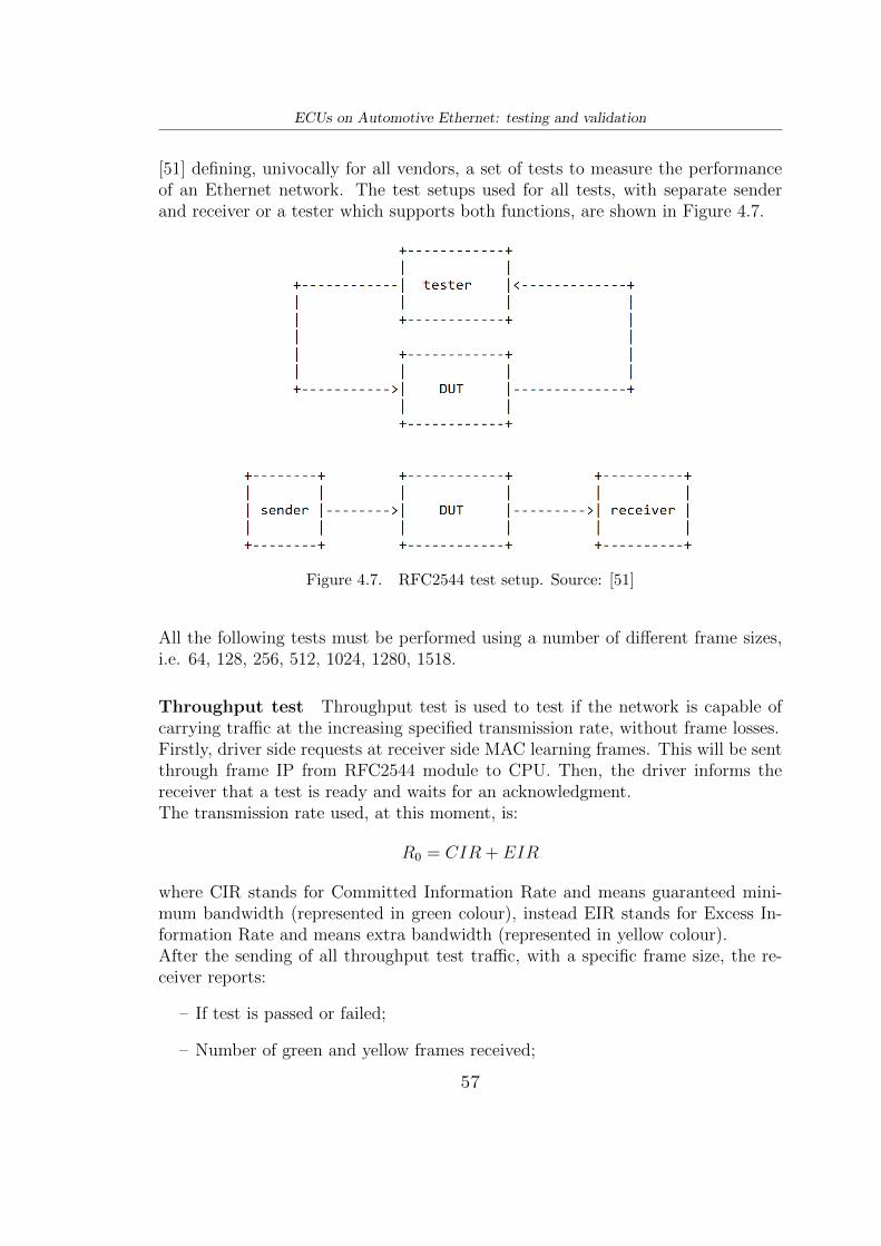
[51] defining, univocally for all vendors, a set of tests to measure the performanceof an Ethernet network. The test setups used for all tests, with separate senderand receiver or a tester which supports both functions, are shown in Figure 4.7.
Figure 4.7. RFC2544 test setup. Source: [51]
All the following tests must be performed using a number of different frame sizes,i.e. 64, 128, 256, 512, 1024, 1280, 1518.
Throughput test Throughput test is used to test if the network is capable ofcarrying traffic at the increasing specified transmission rate, without frame losses.Firstly, driver side requests at receiver side MAC learning frames. This will be sentthrough frame IP from RFC2544 module to CPU. Then, the driver informs thereceiver that a test is ready and waits for an acknowledgment.The transmission rate used, at this moment, is:
R0 = CIR + EIR
where CIR stands for Committed Information Rate and means guaranteed mini-mum bandwidth (represented in green colour), instead EIR stands for Excess In-formation Rate and means extra bandwidth (represented in yellow colour).After the sending of all throughput test traffic, with a specific frame size, the re-ceiver reports:
– If test is passed or failed;
– Number of green and yellow frames received;
57
ECUs on Automotive Ethernet: testing and validation
– For each frame: size, rate, duration;
– Total elapsed time.
Finally, if the number of received frames (yellow and green) is equal to the numberof generated frames, the step test is passed. If a step is not passed or if there is anerror, the transmission rate is reduced by RFC2544 RateStep at:
Ri = Ri−1–R0 ∗RateStep/100
The process ends when the step rate Ri is greater than 10% of R0 or when twoconsecutive steps pass.In fact, to pass an entire test, for a specific frame size, two consecutive step testsmust have passed; instead to fail an entire test at least one of the two step testsmust have failed.[51][61]An example of throughput measurement is shown in Figure 4.8. Instead in Figure4.9 is shown an example of throughput test results.
Figure 4.8. Iterations in the Throughput measurement. Source: [34]
Latency test Latency tests are executed at the same time and same number ofsteps as throughput tests.
58
ECUs on Automotive Ethernet: testing and validation
Figure 4.9. Throughput test results. Source: [61]
Latency value is computed as the time at which a specific frame is received minusthe time at which a frame is fully transmitted.
Latency = Received T imestamp–Sent T imestamp
The RFC says that the test must be repeated at least 20 times and an average istaken into consideration.The test contains:
– If test is passed or failed (Traffic Loss or not);
– Number of green and yellow frames received;
– For each frame: size, rate, duration;
– Total elapsed time.
In Figure 4.10 is shown an example of latency test results.
Frame Loss test Frame loss test is used to test if the network is capable of carry-ing traffic at the increasing specified transmission rate, with limited and acceptablegreen CIR frame losses and without out of sequence frames.As for the throughput tests, driver side requests at receiver side MAC learningframes. Then, the driver informs the receiver that a test is ready and waits for anacknowledgment.Also for frame loss test, the transmission rate used, at this moment, is:
R0 = CIR(green) + EIR(yellow)
59
ECUs on Automotive Ethernet: testing and validation
Figure 4.10. Latency test results. Source: [61]
After the sending of all throughput test traffic, with a specific frame size , thereceiver reports:
– If test is passed or failed;
– Number of green and yellow frames received;
– Frame loss ratio;
– Out-of-sequence events;
– For each frame: size, rate, duration;
– Total elapsed time.
The test is passed if Frame Loss Rate (FLR), computed as
FLR = (TxFrames−RxGreenFrames)/TxFramesis less than a defined Frame Loss Ratio during the first two consecutive test stepsAND Out of Sequence counter is equal to 0.Also for this test if a step is not passed or if there was an error, the transmissionrate is reduced by RFC2544 RateStep at:
Ri = Ri−1–R0 ∗RateStep/100
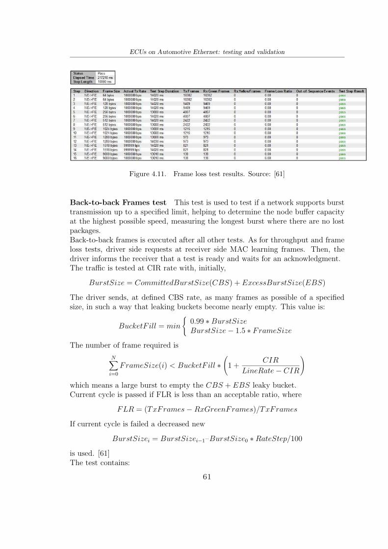
The process ends when the step rate Ri is greater than 10% of R0 or when twoconsecutive steps pass.In fact, to pass an entire test, for a specific frame size, two consecutive step testsmust have passed; instead to fail an entire test at least one of the two step testsmust have failed. [51][61]In Figure 4.11 is shown an example of frame loss test results.
60
ECUs on Automotive Ethernet: testing and validation
Figure 4.11. Frame loss test results. Source: [61]
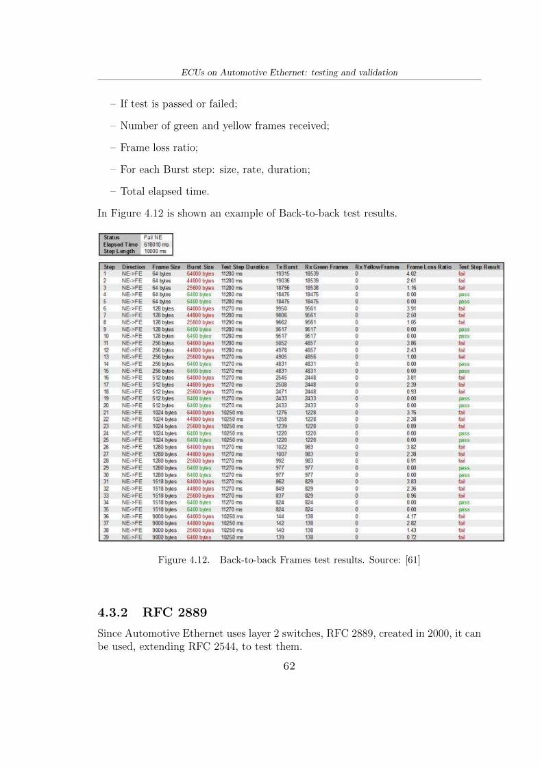
Back-to-back Frames test This test is used to test if a network supports bursttransmission up to a specified limit, helping to determine the node buffer capacityat the highest possible speed, measuring the longest burst where there are no lostpackages.Back-to-back frames is executed after all other tests. As for throughput and frameloss tests, driver side requests at receiver side MAC learning frames. Then, thedriver informs the receiver that a test is ready and waits for an acknowledgment.The traffic is tested at CIR rate with, initially,
The driver sends, at defined CBS rate, as many frames as possible of a specifiedsize, in such a way that leaking buckets become nearly empty. This value is:
BucketF ill = min
(0.99 ∗BurstSizeBurstSize− 1.5 ∗ FrameSize
The number of frame required is
NXi=0
FrameSize(i) < BucketF ill ∗
1 +CIR
LineRate− CIR
!
which means a large burst to empty the CBS + EBS leaky bucket.Current cycle is passed if FLR is less than an acceptable ratio, where
ECUs on Automotive Ethernet: testing and validation
– If test is passed or failed;
– Number of green and yellow frames received;
– Frame loss ratio;
– For each Burst step: size, rate, duration;
– Total elapsed time.
In Figure 4.12 is shown an example of Back-to-back test results.
Figure 4.12. Back-to-back Frames test results. Source: [61]
4.3.2 RFC 2889
Since Automotive Ethernet uses layer 2 switches, RFC 2889, created in 2000, it canbe used, extending RFC 2544, to test them.
62
ECUs on Automotive Ethernet: testing and validation
RFC 2889 is called LAN Switch Benchmarking Methodology and, extending RFC2544, provides methodologies to benchmark switching devices, congestion control,latency, forwarding performance, address handling and address filtering.Using the general test setup described above in RFC 2544, it contains, for dif-ferent port traffic patterns, traffic loads and frame size, the following test types:[28][54][26]
❼ Fully meshed throughput, frame loss and forwarding rates : To test if the switchcan handle fully meshed traffic for different traffic loads. Fully meshed meansfrom all ports to all ports. In fact the test result shows how many frames aretransmitted from all the ports and how many are received on all the portswith the percentage of lost frames, so forwarding rate and throughput;
❼ Partially meshed one-to-many/many-to-one: Instead of sending traffic from allports to all ports, it is sent from one-to-many ports or many-to-one port. Inthis way it can be determined the maximum rate of reception and forwarding.Test result shows forwarding rate for each frame size;
❼ Partially meshed multiple devices : In this test two switches under test areconnected in series to test if they can handle traffic between all ports of multipledevices. Test result shows throughput and forwarding rate for each frame size;
❼ Partially meshed unidirectional traffic: This test is used to show how the switchhandles unidirectionally the traffic between one half test ports to the otherhalf. Unidirectionally means that the transmit ports do not receive framesand the receive ports do not transmit them. Test result shows throughput andforwarding rate for each frame size;
❼ Congestion control : To test if and how the switch handles congestion controlmechanism, for example if the congested port also affects the non-congestedport. The test provides frame loss percentage and forwarding rate for eachframe size;
❼ Forward pressure and maximum forwarding rate: The tests are divided in twoparts. The first part overloads the switch and measure the forward pressure,sending traffic at interframe gap (time pause between packets) of 88 bits (IEEE802.3 standard permits more than 96 bits). If the switch transmits the trafficat less than 96bits, forward pressure is detected. The second part shows themaximum forwarding rate as the highest forwarding rate;
❼ Address caching capacity : The test uses binary search with the purpose ofestablishing the address table (between MAC address and switch ports) sizeof the switch;
❼ Address learning rate: The test provides the address learning rate transmittingframes with multiple address;
63
ECUs on Automotive Ethernet: testing and validation
❼ Errored frames filtering : Test if the switch filters frames with some errors,such as CRC, oversize, alignment, undersize, dribble bit and so on;
❼ Broadcast frame forwarding and latency : The test shows the maximum rateto which broadcast frames are received and forwarded. So throughput andlatency for each frame size and load.
64
Chapter 5
Simulations
This chapter is very useful to understand how the Automotive Ethernet stack andthe related real-time protocols (i.e. AVB and TTEthernet) work through sim-ulations. All the simulation environment and the related frameworks used areopen-source.
5.1 Simulation environment
For simulating Automotive Ethernet will be used: (Objective Modular NetworkTestbed in C++) OMNeT++, which is a simulation library, INET, a frameworksupporting communication networks and (Communication over Real-time Ethernetfor INET) Core4INET which is an extension of INET for real-time Ethernet onAutomotive field.
5.1.1 OMNeT++
OMNeT++[45] is a discrete event network simulation framework, used in manyapplications, such as: queueing networks, communication networks, multiproces-sors systems, performance evaluation and so on. Although OMNeT ++ is oftenknown as a network simulator, in reality, by itself, it is not because it includesthe infrastructure and tools to simulate, but not the components to model, specif-ically, computer, ECU, queueing networks. For this purpose INET framework andCore4INET will be used. [46]A model in OMNeT++ is composed by: simple modules, compound modules, con-nections and parameters.In network simulations, simple modules are implemented in C++ and representsources and sinks, for example protocol entities, such as TCP, routing tables and soon. Compound modules, instead, are more simple modules together or, hierarchi-cally, many other compound modules, such as hosts or routers. Connections link
65
Simulations
input, output and in/out gates to exchange messages. Finally parameters are usedto configure data of the modules.An OMNeT++ project consist of: its (Domain Specific Language) DSL in a .ned(Network Topology Description) file containing the architecture of the network,viewable both textually in the editor and graphically in the IDE; .ini file contain-ing simulation settings and parameters.After simulating, results are created in a folder where scalar and vector data canbe extrapolated and then plotted graphically.
5.1.2 INET & CoRE4INET
INET [47] is an open-source framework contains many models for all protocols(Ethernet, TCP, UDP, IP, . . . ) according to all OSI layers. For design and validatenew networks or protocols INET is useful, in fact many research groups, like CoRE,they took it as a basis and extended. [68]CoRE[6] is a research group of Hamburg University of Applied Sciences (HAW-Hamburg) founded by Prof. Dr. Franz Korf and Prof. Dr. Thomas C. Schmidt.This research group created (Communication over Real-Time Ethernet for INET)CoRE4INET (GitHub:[7] and paper: [56]), which is an extension of INET, thatsupports many automotive real-time protocols like those shown in this thesis (i.e.AVB/TSN, AS6802 TTE).Since NED language, used usually in OMNeT++, is a bit complex and long,CoRE4inet also supports an Abstract Network Description Language (ANDL) asplug-in. The advantage is that it is possible to write less code lines respect to NEDfile and then the compilation from ANDL to NED and INI files will be automaticby Eclipse Xtext1.An overview of the simulation environment is shown in Figure 5.1.
5.2 Automotive Ethernet simulation
The objective of simulations is to understand how automotive real-time (AVB,TTE) and not real-time messages (Best-Effort) transit at the same time, whilefinding the time limits under overload conditions.Using the aforementioned environment and related frameworks, it was chosen tosimulate:
– Ethernet AVB (with one class A message and one class B message), usuallyused for multimedia, driver assistance systems and all applications which re-quire latency and jitter in the order of some millisecond;
1Xtext: open-source framework for developing programming and domain-specific languages.[8]
66
Simulations
Figure 5.1. Overview of the simulation environment. Source: [7]
– AS6802 TTEthernet (with one time-triggered message and some best-effortmessages to allow cross traffic), used in powertrain, chassis domains, au-tonomous driving, X-by-wire applications to ensure latency of less than 100µsand jitter in the order of microseconds;
– Best-effort frames, allowing cross-traffic by increasing payloads, to analyse therobustness of real-time Ethernet protocols (i.e. AVB, TTEthernet). In generalcross-traffic increases latency by 500% and jitter by 14x compared to havingno background tasks.[57]
Following the simulation workflow, shown in Figure 5.2, file .andl was written:
Figure 5.2. Simulation workflow from network description (.andl file) to resultanalysis (.elog/.sca/.vec files). Source: [6]
connect ions {segment d e f a u l t {
node1 <❂❂> { ethernetL ink l i n k 1 {bandwidth 100Mb/ s ;l ength 20m;}} <❂❂> switch1 ;
node2 <❂❂> { ethernetL ink l i n k 2 {bandwidth 100Mb/ s ;l ength 10m;}} <❂❂> switch1 ;
node3 <❂❂> { ethernetL ink l i n k 3 {bandwidth 100Mb/ s ;l ength 5m;}} <❂❂> switch1 ;
}}
communication {message stream1 {
sender node1 ;r e c e i v e r s node3 ;payload 350B;per iod 125 us ;mapping {
d e f a u l t : avb { id 1 ; s r C l a s s A; } ;}
}message stream2 {
sender node2 ;r e c e i v e r s node3 ;payload 350B;per iod 250 us ;mapping {
d e f a u l t : avb { id 2 ; s r C l a s s B ; } ;}
}
68
Simulations
message t t t r a f f i c {sender node1 ;r e c e i v e r s node2 , node3 ;payload 46B;per iod 5ms ;mapping {
d e f a u l t : t t { ctID 100 ; } ;}
}message c r o s s t r a f f i c 1 {
sender node1 ;r e c e i v e r s node2 ;payload 1500B;per iod uniform (200 us ,500 us ) ;mapping {
d e f a u l t : be ;}
}message c r o s s t r a f f i c 2 {
sender node2 ;r e c e i v e r s node3 ;payload 1500B;per iod uniform (200 us ,500 us ) ;mapping {
d e f a u l t : be ;}
}message c r o s s t r a f f i c 3 {
sender node3 ;r e c e i v e r s node1 ;payload 1500B;per iod uniform (200 us ,500 us ) ;mapping {
d e f a u l t : be ;}
}}
}
The network, called ”small network” is composed by three nodes and one switch,everything connected with links of 100Mb/s as bandwidth (100Base-T1) of differ-ent lengths (20m, 10m, 5m), as shown in Figure 5.3. A reasonable propagationdelay of maximum 5ns/m of latency is considered.
69
Simulations
Figure 5.3. ”small network” topology.
Node1 sends to node3 AVB messages of class A (payload 350Byte) every 125µs,instead node2 sends to node3 AVB messages of Class B (payload 350Byte) every250µs. Regarding TTE, node1 sends to both node2 and node3 Time-Triggeredmessages (payload 46Byte) with 5ms as period, instead node1 sends messages tonode2 in Best-Effort manner with uniform period between 200µs and 500µs. SameBest-Effort messages are sent from node2 to node3 and from node3 to node1.By combining AVB and TTEthernet traffic, as in Figure 5.4, obviously, it is ex-pected that the tt traffic (Time-Triggered) messages have highest priority overall.Then stream1 (class A AVB) will have higher priority than stream2 (class B AVB).Finally crosstraffic1,2,3 messages will have lowest priority due to their Best-Effortmode, suitable for all legacy IEEE 802.3 Ethernet traffic without any requirementin terms of time (QoS).
Figure 5.4. AVB, TTEthernet and Best-Effort traffic together. Source: [50]
70
Simulations
By generating the network from the .andl file, the .ini and .ned files are createdone for each node and switch and one for the entire network. Inside every .ned fileare imported from libraries (C++) all the pieces to implement the protocols andthe stack, instead inside .ini file are present all configuration parameters such asthe node name, payload, period, MAC, type of message (AVB, TT or BE) and soon.As an example file .ned of a node is shown, graphically, in Figure 5.5, instead file.ned of a switch is shown in Figure 5.6. Regarding file .ini, below, in Figure 5.7, isshown that of node1 (the others change only in the type of message sent/receivedand in the time period).
Figure 5.5. Node1 file .ned.
Inside switch1 AddresTable.txt, read from switch.ini, are contained all MAC ad-dresses, in this case:
The network has been simulated by testing different payloads of the Best-Effortmessages to check cross-traffic. Values used are: 64B, 128B, 256B, 512B, 1024B,1280B, 1500B.Figure 5.8 shows the transit of packets starting from 5ms (time at which the firstTTE packet is generated) from one node to another passing through the switch.In Figure 5.9 is shown the latency for AVB and TTE communications for increasing
71
Simulations
Figure 5.6. Switch file .ned.
Cross Traffic frame size of Best-Effort messages. From the results it can be seenthat TTE has constant very low latency regardless of the increase in cross-trafficand remains independent from the other streams respecting its determinism. In-stead, latency below 2ms, for AVB suitable applications, is equally guaranteed, butthe increase in cross-traffic has a strong impact.This configuration has a balanced throughput for each node as shown in Figure5.10 and obviously there is no dropped packet.Now trying to show the limit of AVB and TTEthernet protocols, some other cross-traffic message and AVB stream is added to overload the whole network. In thiscase 100Mbps bandwidth is nearly saturated as shown in Figure 5.11, in fact thereis some AVB packet dropped. Regarding to latency of TTEthernet is still guar-anteed (41µs, 42µs, 43µs) also in case of an overloaded network, because its fullydeterministic and predictable communication delays and precisions are certainlyguaranteed and predefined. The traffic generated by critical messages will alwaystake precedence over traffic generated by non-critical messages.Instead, regarding AVB, latency grows and many messages are dropped whenadding more messages to overload the network.Summarizing, Table 5.1 shows the results of the simulations mentioned above.
72
Simulations
Figure 5.7. Node1 file .ini.
73
Simulations
Figure 5.8. Transit of messages on the network.
Simulationsincreasing the
network overload
Max AVBLatency(µs)
Max TTELatency(µs)
AVBPacketsdropped
TTEPacketsdropped
1 TTE, 2 AVB 160 41 No No1 TTE, 2 AVB, 3 BE 353 41 No No1 TTE, 2 AVB, 6 BE 389 41 No No
1 TTE, 2 AVB, 12 BE 533 42 Yes (15) No
2 TTE, 4 AVB, 12 BE 693 42Yes (too
high)No
↓ ↓ 43Yes (too
high)No
43Yes (too
high)No
Table 5.1. Latencies and packets dropped for various configurationswith increasing traffic.
74
Simulations
Figure 5.9. Maximum and average end-to-end Latency (AVB and TSN) fordifferent Cross Traffic frame size.
Figure 5.10. Throughput of each node in regular conditions (no overload).
75
Simulations
Figure 5.11. Throughput of each node in overload conditions.
76
Chapter 6
Conclusions and future
developments
It is certainly possible to understand that Automotive Ethernet needs to be used inthe vehicle as soon as possible due to the above-mentioned benefits. An overviewof all protocols, standards and differences with other automotive networks wasprovided. Testing and validation methodologies have been provided for ECUs in-terconnected over Ethernet and three nodes exchanging real-time (AVB, TTE) andnon-real-time messages (BE) have been simulated, studying their advantages andlimits, thanks to open-source frameworks available from a research center at theUniversity of Hamburg.However, before being put into the vehicle, ECUs on Ethernet need to be tested andphysically simulated. For these purposes there are many boards and test benchesprovided by Vector, Xena, Keysight, NXP, Texas Instruments and other testingcompanies with a cost ranging from $249 to $6000 for something more professional.A possible future development of this thesis could be to use these boards or testbenches to be able to test and simulate, in practice, two or more ECUs connectedon Automotive Ethernet with the methodologies mentioned in this thesis. An-other important development can be test and simulate mixed network with CAN,FlexRay and Ethernet protocols.
[2] Bello, Lucia Lo. The case for ethernet in automotive communications. ACMSIGBED Review, 8(4):7–15, 2011.
[3] Brunthaler, Sebastian and Waas, Thomas and Kucera, Markus. On verify andvalidate a next generation automotive communication networka. In PECCS,pages 121–127, 2019.
[4] Charles M. Kozierok and Colt Correa and Robert B. Boatright and JeffreyQuesnelle. Automotive Ethernet: The Definitive Guide. Intrepid Control Sys-tems, 2014. 978-0-9905388-06.
[5] Comite International Special des Perturbations Radioelectriques. https://
webstore.iec.ch/publication/26122&preview, 2016.
[6] CoRE Research Group. Core research group. https://core-researchgroup.de/about/core-group.html.
[7] CoRE Research Group. Core4inet. https://github.com/CoRE-RG/
[12] Fu, Shousai and Chen, HZJ. Time sensitive networking technology overviewand performance analysis. ZTE COMMUNICATIONS, 16(4), 2018.
[13] Hank, Peter and Suermann, Thomas and Muller, Steffen. Automotive ether-net, a holistic approach for a next generation in-vehicle networking standard.In Advanced Microsystems for Automotive Applications 2012, pages 79–89.Springer, 2012.
[14] IEEE 802.3 Ethernet Working Group. 10mb/s single twisted pair ethernet callfor interest. https://www.ieee802.org/3/cfi/0716_1/CFI_01_0716.pdf,2019.
[15] IEEE Working Group. Ieee standard for local and metropolitan area networks- virtual bridged local area networks amendment 12: Forwarding and queuingenhancements for time-sensitive streams. IEEE Std 802.1Qav-2009 (Amend-ment to IEEE Std 802.1Q-2005), pages C1–72, 2010.
[16] IEEE Working Group. Ieee standard for local and metropolitan area networks–virtual bridged local area networks amendment 14: Stream reservation protocol(srp). IEEE Std 802.1Qat-2010 (Revision of IEEE Std 802.1Q-2005), pages1–119, 2010.
[17] IEEE Working Group. Ieee standard for layer 2 transport protocol for timesensitive applications in a bridged local area network. IEEE Std 1722-2011,pages 1–65, 2011.
[18] IEEE Working Group. Ieee standard for local and metropolitan area networks- timing and synchronization for time-sensitive applications in bridged localarea networks. IEEE Std 802.1AS-2011, pages 1–292, 2011.
[19] IEEE Working Group. Ieee standard for a transport protocol for time-sensitiveapplications in bridged local area networks. IEEE Std 1722-2016 (Revision ofIEEE Std 1722-2011), pages 1–233, 2016.
[20] IEEE Working Group. Ieee standard for local and metropolitan area networks– bridges and bridged networks – amendment 26: Frame preemption. IEEEStd 802.1Qbu-2016 (Amendment to IEEE Std 802.1Q-2014), pages 1–52, 2016.
[21] IEEE Working Group. Ieee standard for local and metropolitan area networks– bridges and bridged networks - amendment 25: Enhancements for scheduledtraffic. IEEE Std 802.1Qbv-2015 (Amendment to IEEE Std 802.1Q-2014 asamended by IEEE Std 802.1Qca-2015, IEEE Std 802.1Qcd-2015, and IEEEStd 802.1Q-2014/Cor 1-2015), pages 1–57, 2016.
[22] IEEE Working Group. Ieee standard for local and metropolitan area networks–bridges and bridged networks – amendment 31: Stream reservation protocol(srp) enhancements and performance improvements. IEEE Std 802.1Qcc-2018(Amendment to IEEE Std 802.1Q-2018 as amended by IEEE Std 802.1Qcp-2018), pages 1–208, 2018.
[23] IEEE Working Group. Ieee standard for local and metropolitan area networks–timing and synchronization for time-sensitive applications. IEEE Std 802.1AS-2020 (Revision of IEEE Std 802.1AS-2011), pages 1–421, 2020.
[24] IEEE802.3 Working Group. 10g+ automotive ethernet electrical phys. https://www.ieee802.org/3/cfi/0319_1/CFI_01_0319.pdf, March 2019. Call forInterest Consensus Meeting, Vancouver, BC.
[25] International Organization for Standardization. Road vehicles — Diagnosticcommunication over Internet Protocol (DoIP) — Part 2: Transport protocol
[36] Michael Johas Teener (Mikejt). Avb connections. https://commons.
wikimedia.org/wiki/File:AVB-Ethernet-connections.pdf.[37] Michael Johas Teener (Mikejt). Clock-master. https://upload.wikimedia.
org/wikipedia/en/6/64/Clock-Master.pdf.[38] Michael Johas Teener (Mikejt). Traffic-shaping. https://upload.
wikimedia.org/wikipedia/en/d/d3/Traffic-shaping.pdf.[39] Navet, N. and Song, Y. and Simonot-Lion, F. and Wilwert, C. Trends in
automotive communication systems. Proceedings of the IEEE, 93(6):1204–1223, 2005.
[40] Navet, Nicolas and Simonot-Lion, Francoise. In-vehicle communicationnetworks-a historical perspective and review. Technical report, University ofLuxembourg, 2013.
[41] OPEN ALLIANCE TC8 Members. Open alliance automotive ethernet ecutest specification layer 1. http://opensig.org/download/document/271/
OA_Automotive_Ethernet_ECU_TestSpecifications_Version_3.0.zip.[42] OPEN ALLIANCE TC8 Members. Open alliance automotive ethernet ecu
test specification layer 2. http://opensig.org/download/document/271/
omnetpp/SimulationManual.pdf.[47] OpenSim Ltd. Omnet++ simulation manual. https://inet.omnetpp.org/.[48] Pattavina, Achille. Reti di Telecomunicazioni: Networking e Internet.
McGraw-Hill, 2007.[49] Porter, Donovan. 100base-t1 ethernet: the evolution of automotive networking.
Texas Instruments, Techn. Ber, 2018.[50] Soeren Rumpf, Till Steinbach, Franz Korf, and Thomas C Schmidt. Soft-
ware stacks for mixed-critical applications: Consolidating ieee 802.1 avband time-triggered ethernet in next-generation automotive electronics. In2014 IEEE Fourth International Conference on Consumer Electronics Berlin(ICCE-Berlin), pages 14–18. IEEE, 2014.
[51] S. Bradner and J. McQuaid. Benchmarking Methodology for Network Inter-connect Devices. RFC 2544, March 1999.
[52] Softing Automotive Electronics GmbH. Diagnostic communication over in-ternet protocol. https://automotive.softing.com/fileadmin/sof-files/pdf/de/ae/poster/DoIP_faltblatt_softing.pdf.
20with_20RFC_2028891445071217740.pdf.[55] Spirent Developers, Critical New Test Challenges Facing. Testing automotive
ethernet phy. Engineer, 2013.[56] Till Steinbach, Hermand Dieumo Kenfack, Franz Korf, and Thomas C Schmidt.
An extension of the omnet++ inet framework for simulating real-time ethernetwith high accuracy. In Proceedings of the 4th International ICST Conferenceon Simulation Tools and Techniques, pages 375–382, 2011.
[57] Till Steinbach, Hyung-Taek Lim, Franz Korf, Thomas C Schmidt, DanielHerrscher, and Adam Wolisz. Beware of the hidden! how cross-traffic af-fects quality assurances of competing real-time ethernet standards for in-carcommunication. In 2015 IEEE 40th Conference on Local Computer Networks
(LCN), pages 1–9. IEEE, 2015.[58] Steiner, Wilfried and Bauer, Gunther and Hall, Brendan and Paulitsch,
Michael and Varadarajan, Srivatsan. Ttethernet dataflow concept. In 2009Eighth IEEE International Symposium on Network Computing and Applica-tions, pages 319–322. IEEE, 2009.
know-how/_technical-articles/Pressbook_EN_2018.pdf, 2018.[68] Antonio Virdis and Michael Kirsche. Recent advances in network simulation.
EAI/Springer Innovations in Communication and Computing, 2019.[69] Wikipedia. Ttethernet. https://en.wikipedia.org/wiki/TTEthernet.[70] Xena Networks. Automotive ethernet. https://xenanetworks.com/
whitepaper/automotive-ethernet/.[71] Zhao, Lin and He, Feng and Li, Ershuai and Lu, Jun. Comparison of time
sensitive networking (tsn) and ttethernet. In 2018 IEEE/AIAA 37th DigitalAvionics Systems Conference (DASC), pages 1–7. IEEE, 2018.
[72] Zimmerman, G and Jones, P and Lewis, J and Beruto, P and Graber, S andStewart, H. Ieee p802. 3cg 10mb/s single pair ethernet: A guide. In Task Forcemeeting materials, 2019.