+ All Categories
Home > Documents > Expander Operated Gas Processing - · PDF fileExpander Operated Gas Processing April, 2015 pg....

Expander Operated Gas Processing - · PDF fileExpander Operated Gas Processing April, 2015 pg....

Date post: 16-Mar-2018
Category:
Upload: trannhi
View: 224 times
Download: 1 times
Share this document with a friend
16
Expander Operated Gas Processing: Cooler NGL (Natural Gas Liquid) temperatures and maximized uptime with Helidyne’s NGL Expander design. Author: Joseph James Mechanical Engineer April, 2015 Specifications: Flowrates 1-10 mmscfd Max. Pressure 1440 psi Min. Temperature -50 °F Power Generation up to 50 kW
Transcript

Expander Operated Gas Processing April, 2015

L’

Expander Operated Gas Processing:

Cooler NGL (Natural Gas Liquid) temperatures and maximized

uptime with Helidyne’s NGL Expander design.

Author:

Joseph James

Mechanical Engineer

April, 2015

Specifications:

Flowrates 1-10 mmscfd

Max. Pressure 1440 psi

Min. Temperature -50 °F

Power Generation up to 50 kW

Expander Operated Gas Processing April, 2015

Table of Contents

Executive Summary 1

Introduction 2

JT Skid Configuration 3

JT/MRU Skid Configuration 4

Expander Skid Configuration 5

How It Works 6

Empirical Data 8

Mathematical Validation 11
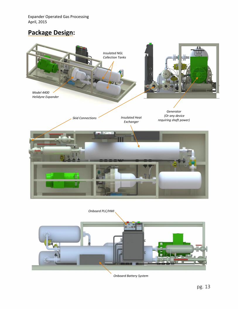
Package Design 13

Contact Us 14

Expander Operated Gas Processing April, 2015

pg. 1

Executive Summary:

Recent advancements in fracking and remote well operations have proven to be a very effective

method to stimulate wells and increase production. Unfortunately, infrastructure development is either

not feasible or delayed years to service remote wells making gaseous product transportation an

economic impossibility. Consequently, remote well and NGL processing equipment are the only viable

means of keeping production numbers high. Liquefying as much of the wellhead gas as possible makes

trucking transports possible, however, this creates challenges when trying to maximize wellhead gas

recovery. Despite all efforts, over 150 million cubic feet of natural gas is flared each day in remote areas

of North Dakota.

Helidyne’s NGL drop-out package offers a solution that minimizes gas flaring, reduces

downtime, and generates electricity as a bi-product. Wellhead gas is typically cooled through a high-

pressure / JT cooling system. This cooling process condenses the “heavy” gasses into a liquid making

remote truck transport economical. The system outlet temperature dictates the amount of heavy liquids

recovered; lower temperatures produce more NGLs. Depending on wellhead gas composition, these

“JT” skids have the capability of reaching temperatures of -30 °F. Since the Helidyne expander extracts

energy from the high pressure fluid in addition to utilizing the JT effect, it will always produce a colder

exhaust temperature than any JT valve. This results in more liquid recovery and higher revenue for the

customer. On average, the Helidyne expander will produce a 10-30 °F colder exhaust temperature than

a JT valve. This document illustrates a few configurations used within the industry, empirical data of the

Helidyne expander, and how the Helidyne NGL drop-out package is different.

Helidyne’s Model 4400 Expander

Figure 1

Expander Operated Gas Processing April, 2015

pg. 2

Introduction:

Wellhead gas is always a byproduct of oil production and needs to be separated. The flowrate of

separated gas varies from well-to-well with the most common wells producing about 3-5 mmscfd of gas.

This separated gas contains rich components like propane and butanes with a methane mol % ranging

from 40% (wetter gas) to 80% (dryer gas). Because these sites are in remote locations, typically no

infrastructure (including grid power) is present to transport the gas. Shipping the gas via freight isn’t

economical as the transport cost per cubic foot is unreasonable. However, liquefying these gases

reduces the volume making transport profitable.

There are several approaches to liquefying

NGLs. The most common method is by a heat

exchanger coupled with a JT skid. In this scenario, the

wellhead gas is compressed from 30-40 psi up to 1000

psi. The temperature of the gas is increased to 100-

150 °F at this high pressure. It then goes through a

heat exchanger that lowers the temperature to 20-50

°F while keeping it at that high pressure (some of the

heavy gases liquefy at this stage and drop out). The gas is then fed through a JT valve which uses the

Joule Thompson effect to lower the fluid temperature as it passes from a high-to-low pressure system.

This JT valve typically drops the pressure down to 100-400 psi and cools the gas in the range of -30 to -

10 °F. Heavy gases liquefy and are extracted from the main gas stream. The desired end product is a gas

with high methane content (typically between 80% and 90% methane).

Occasionally, if the wellhead gas is

extremely rich (40%-60% methane), a MRU

(mechanical refrigeration unit) will be installed

with a JT valve to cool the gas further. Rich gasses

have a smaller change in temperature when only

utilizing the JT effect thus requiring additional

cooling from an MRU to liquefy gas. These

refrigeration units also require an on-site

generator and consume approximately 125 kW.

Adding an MRU to a gas processing site is an

expensive proposition. It requires a leased MRU,

rented gas-powered generator, and on-going

maintenance as this equipment has proven to be unreliable mechanically and functionally not suited for

North Dakota’s rich gas and extreme environment. The Helidyne expander package replaces the JT valve

and removes the need for an MRU for rich gas wellheads. By having the capability of extracting fluid

energy from the gas stream, resultant temperatures are between 10 and 30 °F lower than a JT valve, and

comparable to a JT+MRU system. But, unlike the MRU, the Helidyne expander generates power instead

of consuming it; removing any need for an on-site generator and the MRU itself.

A Helidyne Expander

will produce lower NGL

temperatures than any

JT valve. Always.

A Helidyne expander is a

self-starting, fully

automated, mechanical

device that utilizes only

one electric motor.

Expander Operated Gas Processing April, 2015

pg. 3

Below are two of the most common NGL drop-out skid configurations. The first diagram (figure

2) shows a JT skid configuration, which is typically used for a leaner wellhead gas (70% methane content

or higher). The second diagram (figure 3) shows the typical configuration for a wellhead that provides a

rich gas (Methane content as low as 40%). Richer gases have steeper “p vs h” charts (see page 7), which

renders the JT effect less efficient; thus requiring additional cooling from a generator-powered

refrigeration unit.

State Pressure Temperature Flow Description

1 30 to 40 psi 50 to70 °F Rich wellhead gas (methane content between 40% and 80%)

2 1000 psi 100 to 150 °F Hot, high pressure wellhead gas

3 1000 psi 30 to 60 °F Cooled, high pressure wellhead gas/liquid mixture

4 150 psi 30 to 60 °F Dropped out liquids collected from tank #1

5 1000 psi 30 to 60 °F Cooled, high pressure wellhead gas (higher methane content then states 1-3)

6 150 psi -30 to 0 °F Cold, low pressure gas/liquid mixture

7 150 psi -30 to 0 °F Dropped out liquids collected from tank #2

8 150 psi -30 to 0 °F Cold, low pressure gas (>80% methane content), used for heat exchanger

9 150 psi 30 to 70 °F Cooled, low pressure “lean” gas sent for processing

Reciprocating

Compressor

NGL

Collection

Tank

Separator

Tank #1

Separator

Tank #2

JT Throttling

Valve

Shell and Tube

Heat Exchanger

1

2

3

5

4

6

8

7

9

JT Skid Configuration (Typically used for leaner wellhead

gas applications, methane > 70%)

Figure 2

Expander Operated Gas Processing April, 2015

pg. 4

JT/MRU Skid Configuration

(Typically used for rich wellhead

gas applications, methane < 70%)

State Pressure Temperature Flow Description

1 30 to 40 psi 50 to70 °F Rich wellhead gas (methane content between 40% and 80%)

2 1000 psi 100 to 150 °F Hot, high pressure wellhead gas

3 1000 psi 30 to 60 °F Cooled, high pressure wellhead gas/liquid mixture

4 150 psi 30 to 60 °F Dropped out liquids collected from tank #1

5 1000 psi 30 to 60 °F Cooled, high pressure wellhead gas (higher methane content than states 1-3)

6 150 psi -30 to 0 °F Cold, low pressure gas/liquid mixture

7 150 psi -30 to 0 °F Dropped out liquids collected from tank #2

8 150 psi -30 to 0 °F Cold, low pressure gas( higher methane content then states 1-6)

9 150 psi -50 to -20 °F Extra cold, low pressure gas/liquid mixture

10 150 psi -50 to -20 °F Dropped out liquids from tank #3

11 150 psi -50 to -20 °F Extra cold, low pressure gas used for heat exchanger (>80% methane content)

12 150 psi 10 to 70 °F Cooled, low pressure “lean” gas sent for processing

NGL

Collection

Tank

Separator

Tank #1

Separator

Tank #2

Separator

Tank #3

JT Throttling

Valve

Shell and Tube

Heat Exchanger Reciprocating

Compressor

Mobile Refrigeration Unit

(MRU)

125 kW

Generator

1

2

3

5 6

4

7

8

9

11

12

10

Figure 3

Expander Operated Gas Processing April, 2015

pg. 5

Below is the configuration for a Helidyne expander NGL drop-out skid. As shown in the tables,

using a Helidyne expander combines the simplicity of a JT configuration, while producing the cold

temperatures of a JT+MRU Skid. The Helidyne expander is a mechanical device (with self-cleaning

rotors) that only utilizes one electric motor (oil pump). This translates to 1000’s of hours of runtime

without maintenance. As previously mentioned, the bi-product of using a Helidyne expander is available

shaft power capable of producing up to 50 kW of electricity. This can be used to operate a control room,

run climate control for operators, power heating equipment to

prevent potential system freezes, or drive any auxiliary device.

State Pressure Temperature Flow Description

1 30 to 40 psi 50 to70 °F Rich wellhead gas (methane content between 40% and 80%)

2 1000 psi 100 to 150 °F Hot, high pressure wellhead gas

3 1000 psi 30 to 60 °F Cooled, high pressure wellhead gas/liquid mixture

4 150 psi 30 to 60 °F Dropped out liquids collected from tank #1

5 1000 psi 30 to 60 °F Cooled, high pressure wellhead gas (higher methane content then states 1-3)

6 150 psi -50 to -20 °F Cold, low pressure gas/liquid mixture

7 150 psi -50 to -20 °F Dropped out liquids collected from tank #2

8 150 psi -50 to -20 °F Cold, low pressure gas (>80% methane content), used for heat exchanger

9 150 psi 10 to 70 °F Cooled, low pressure “lean” gas sent for processing

Expander Skid

Configuration (Applications include both

dry and wet gas wells)

Reciprocating

Compressor

Shell and Tube

Heat Exchanger

Separator

Tank #1 Separator

Tank #2

NGL

Collection

Tank

Helidyne Expander

1

2

3

4

5

6

7

8

9

9

Up to 50 kW of

available shaft power.

Figure 4

Expander Operated Gas Processing April, 2015

pg. 6

How It Works: The Helidyne expander is a positive displacement, planetary rotor

design. In other words, the volume ratio from inlet-to-exhaust is 1:1 and can be

assumed to behave like a hydraulic motor (for incompressible flows only, Mach

< .3). Rotors (3 or 4 rotor configuration) are designed with a helical twist that

mesh with adjacent rotors when assembled together. As the rotors rotate in the

same direction they form a progressive working cavity within the rotor mesh.

Each revolution produces two or three cycles for a 4 or 3 rotor configuration

respectively. Figure 7 illustrates the shape of the volume within the 4 rotor

machine.

During operation, the inlet of the machine is always open to the gas

source, thus maintaining a constant fluid density. After turning half a rotation,

the inlet closes completely, enclosing the gas in the cavity. After which, the

rotors open on the backside exhausting the gas. As the leading volume of gas is

being exhausted, a new volume of gas is entering on the frontend creating 2

power cycles per revolution.

Shaft power produced by the expander is calculated using the hydraulic

power equation (due to the 1:1 ratio):

𝑃𝑠ℎ𝑎𝑓𝑡 = ∆𝑝�̇�𝐴𝑐𝑡𝑢𝑎𝑙 𝑅𝑜𝑡𝑜𝑟𝐸𝑣𝑜𝑙 1

Where: 𝑃𝑠ℎ𝑎𝑓𝑡 = 𝑆ℎ𝑎𝑓𝑡 𝑝𝑜𝑤𝑒𝑟

∆𝑝 = 𝑃𝑟𝑒𝑠𝑠𝑢𝑟𝑒 𝑎𝑐𝑟𝑜𝑠𝑠 𝑡ℎ𝑒 𝑟𝑜𝑡𝑜𝑟𝑠 �̇�𝐴𝑐𝑡𝑢𝑎𝑙 𝑅𝑜𝑡𝑜𝑟 = "actual" flow rate 𝑡ℎ𝑟𝑜𝑢𝑔ℎ 𝑡ℎ𝑒 𝑟𝑜𝑡𝑜𝑟𝑠 𝐸𝑣𝑜𝑙 = 𝐸𝑥𝑝𝑎𝑛𝑑𝑒𝑟 𝑉𝑜𝑙𝑢𝑚𝑒𝑡𝑟𝑖𝑐 𝐸𝑓𝑓𝑖𝑐𝑖𝑒𝑛𝑐𝑦

The power produced from the expander is the byproduct of using it in

an NGL application, not the objective. Gas cooling is the primary goal and

should be maximized. As per its definition, an expander captures energy within

a fluid by having it perform work on a mechanical device (usually a rotor or a

blade). This reduces the enthalpy (internal energy plus the product of volume

and pressure), which reduces the heat content of the fluid. JT valves use the Joule Thompson effect

which is an isenthalpic process (enthalpy remains constant) where total energy is conserved in adiabatic

gas expansion (no heat exchanged, no work performed). This process causes an increase in potential

energy but a decrease in kinetic energy (decrease in temperature) but total energy is conserved. In an

expander, on the other hand, gas performs positive work during expansion which reduces its enthalpy

(reducing total energy) thus cooling the gas more than a JT valve.

Gas “Packet”

Rotors at full torque position

(half cycle or quarter turn)

Shape of a gas volume

passing through the Expander

Figure 5

Figure 7

Rotors at starting position

(beginning of a cycle)

Figure 6

Expander Operated Gas Processing April, 2015

pg. 7

Each fluid composition has a spectrum of cooling capability called the isentropic range.

Removing all the potential energy from a fluid stream would be an “ideal isentropic process” (or in other

words, a system with 100% efficiency). Depending on expander efficiency, the enthalpy removed will lie

somewhere between its isentropic and isenthalpic temperatures.

A Mollier chart (Figure 8), which graphs pressure versus enthalpy, illustrates this concept

further. A brief explanation of this chart is beneficial. This specific Mollier chart uses methane as the

fluid; the green lines indicate isothermal processes, black lines are isentropic processes, and the brown

line is the saturated-state bell curve. The black dot is the initial state of this particular example (1000 psi

@ 30 °F). The red line shows the cooling process of an isenthalpic process (or JT process). Since an

expander removes energy, the reduced enthalpy lowers the temperature further as shown by the purple

line. The theoretical maximum cooling for this example, without an external heat pump, is shown by the

blue line. Notice all three scenarios have the same exhaust pressure (150 psi) but different

temperatures.

The change in enthalpy is calculated by:

∆ℎ = 𝔑𝑖𝑛𝑍𝑖𝑛𝑇𝑖𝑛𝐸𝑣𝑜𝑙 (1 −𝑝𝑜𝑢𝑡

𝑝𝑖𝑛) 2

Where: ∆ℎ = 𝐶ℎ𝑎𝑛𝑔𝑒 𝑖𝑛 𝑒𝑛𝑡ℎ𝑎𝑙𝑝𝑦 𝔑𝑖𝑛 = 𝑅𝑒𝑎𝑙 𝑔𝑎𝑠 𝑐𝑜𝑛𝑠𝑡𝑎𝑛𝑡 𝑍𝑖𝑛 = 𝑇ℎ𝑒 𝑐𝑜𝑚𝑝𝑟𝑒𝑠𝑠𝑖𝑏𝑖𝑙𝑖𝑡𝑦 𝑓𝑎𝑐𝑡𝑜𝑟 𝑎𝑡 𝑡ℎ𝑒 𝑒𝑥𝑝𝑎𝑛𝑑𝑒𝑟 𝑖𝑛𝑙𝑒𝑡 𝑝𝑖𝑛 = 𝐸𝑥𝑝𝑎𝑛𝑑𝑒𝑟 𝑖𝑛𝑙𝑒𝑡 𝑝𝑟𝑒𝑠𝑠𝑢𝑟𝑒 𝑝𝑜𝑢𝑡 = 𝐸𝑥𝑝𝑎𝑛𝑑𝑒𝑟 𝑜𝑢𝑡𝑙𝑒𝑡 𝑝𝑟𝑒𝑠𝑠𝑢𝑟𝑒 𝑇𝑖𝑛 = 𝐸𝑥𝑝𝑎𝑛𝑑𝑒𝑟 𝑖𝑛𝑙𝑒𝑡 𝑇𝑒𝑚𝑝𝑒𝑟𝑎𝑡𝑢𝑟𝑒 𝐸𝑣𝑜𝑙 = 𝐸𝑥𝑝𝑎𝑛𝑑𝑒𝑟 𝑣𝑜𝑙𝑢𝑚𝑒𝑡𝑟𝑖𝑐 𝑒𝑓𝑓𝑖𝑐𝑖𝑒𝑛𝑐𝑦

Figure 8

Expander Operated Gas Processing April, 2015

pg. 8

Which is derived from the conservation of energy:

𝑃𝑠ℎ𝑎𝑓𝑡 = �̇�∆ℎ 3

Where: �̇� = 𝐸𝑥𝑝𝑎𝑛𝑑𝑒𝑟 𝑖𝑛𝑙𝑒𝑡 𝑚𝑎𝑠𝑠 𝑓𝑙𝑜𝑤𝑟𝑎𝑡𝑒

Equation 2 demonstrates a higher pressure ratio and greater expander efficiency will yield lower

temperatures. Or, in terms of the above Mollier Chart (figure 8), the greater the pressure ratio and

expander efficiency, the closer the purple line moves toward the blue line and higher isentropic

efficiency. Current Helidyne expander volumetric efficiencies are approximately 20-40% (depending on

the application). As machining processes become more advanced, leakage within the expander system

will be reduced which will increase volumetric efficiency resulting in lower exhaust temperatures.

The Helidyne expander has a unique design that allows it to be the only expander on the market

suitable for the harsh conditions experienced in a total-flow NGL application. The current rotor design

for Model 4400 allows for pressure drops of up to 1440 psi, flows up to 10 mmscfd, and power

generation up to 50 kW. However, the most important capability of the Helidyne expander is its ability

to process 2-phase expansion and be self-cleaning. This quality alone makes the Helidyne expander a

more effective and reliable option over other expander types.

Empirical Data:

The Helidyne expander has been tested using air, nitrogen, and pipeline natural gas to validate

the above mathematical models. Helidyne’s test site is located in St. George, Utah at the Red Rock

Generation Facility and includes a 1300 HP natural gas fueled compressor, PLC operated control room,

and a piping infrastructure to run various tests (see figure 9). This test site is capable of producing a flow

of 6 mmscfd at 1000 psi using pipeline natural gas or nitrogen (tests using air performed at a different

location).

The Helidyne Red Rock Test Site located in St. George, Utah

Figure 9

Expander Operated Gas Processing April, 2015

pg. 9

Several 24 hour tests were completed using pipeline quality natural gas. These tests were

designed to measure various system performances including pressure/flow variance, stability, and

exhaust cooling. The power produced was controlled using a flow control valve upstream that regulated

the pressure to the expander. “System Pressure” is the line pressure upstream of the control valve,

“expander inlet pressure” is the line pressure between the flow control valve and the expander (and is

the pressure used to compare with a JT process), and the “exhaust pressure” is the line pressure after

the expander.

Figure 10 illustrates results of the first half of a 24 hour test. The first graph displays the

expander having a varying system pressure (dark blue line, ranging from 450 to 850 psi) while

maintaining a constant 15 kW power output (teal line). In addition to testing system stability, this

provided different system temperatures that varied with system pressure.

The second graph shows the temperatures of the system before the flow control valve (red line),

the temperatures right before the expander (the purple line), and the exhaust gas temperatures (green

line). A set of data points (indicated by the red line) are displayed below the temperature graph. These

values will be used to compare the performance of the Helidyne expander versus a JT valve.

Time Stamp 10/20/2014 18:00

System Pressure 557.80 psi

Expander Inlet Pressure 350.08 psi

Exhaust Pressure 49.30 psi

System Temperature 92.6 °F

Inlet Temperature 82.3 °F

Exhaust Temperature 53.1 °F

Power 14.94 kW

Figure 10

Expander Operated Gas Processing April, 2015

pg. 10

The numbers in the table of figure 10 can be reproduced using NIST (National Institute of

Standards and Technology) data and also give the exhaust temperature of a JT valve under the same

application (see figure 11). This validates equations 1-3 (note: pressures are absolute):

Line 1 = System State

Line 2 = Expander Inlet State

Line 3 = Rotor Inlet

Line 4 = Expander Exhaust

Line 6 = JT Temperature

Drop (for comparison)

As figure 11 shows, the Helidyne expander has a 13 degree cooler temperature than a similar

test with a JT valve. This is because the expander extracts fluid energy from the flow and converts it to

mechanical work. As equation 2 shows, a greater pressure ratio will yield a greater change in enthalpy,

which translates to cooler temperatures. The above test had a 300 psi drop across the expander (as per

the 15 kW protocol requirement). If a greater

power was desired, the pressure drop across

the expander could be raised to the available

500 psi drop and the exhaust gas would be a

lower temperature than line 4 of figure 11.

It is important to note that exhaust

temperatures will vary depending on fluid

composition, pressure drop, initial temperature,

ambient temperature, and flowrate (affects

expander volumetric efficiency). The Mollier

chart in figure 8 shows methane (at certain

points, pressures, and temperatures) displaying

very curvy isothermal lines. In other words,

methane promotes very good cooling when dropping from warmer, higher to lower pressures. However,

when the fluid composition changes by reducing the methane mol percentage, the isothermal lines

become much steeper, similar to the left-hand side of figure 8’s methane chart. In short, lower mol

percentage methane composition makes JT cooling less effective for wellhead gas. Each well will have its

own fluid composition, flow, temperature, and pressures that will produce unique results when using a

Helidyne expander.

Isenthalpic Process

The Helidyne Expander’s

versatile profile includes

flows from 1-10 mmscfd,

pressures up to 1440 psi,

and temperatures down

to -50 °F.

Figure 11

Expander Operated Gas Processing April, 2015

pg. 11

Mathematical Validation:

𝑃𝑠ℎ𝑎𝑓𝑡 = �̇�∆ℎ

14.94 𝑘𝑊 + 4.8 𝑘𝑊 (𝑃𝑎𝑟𝑎𝑠𝑖𝑡𝑖𝑐 𝐿𝑜𝑠𝑠𝑒𝑠) = 19.74 𝑘𝑊 = �̇� ∙ 16.12𝑘𝐽

𝑘𝑔

�̇� =19.74

𝑘𝐽𝑘𝑔

16.12𝑘𝐽𝑠

�̇� = 1.225 𝑘𝑔

𝑠

�̇� = 𝜌�̇�𝐴𝑐𝑡𝑢𝑎𝑙

𝑊ℎ𝑒𝑟𝑒:

𝜌 = 𝐹𝑙𝑢𝑖𝑑 𝐷𝑒𝑛𝑠𝑖𝑡𝑦

�̇�𝐴𝑐𝑡𝑢𝑎𝑙 =�̇�

𝜌

�̇�𝐴𝑐𝑡𝑢𝑎𝑙 𝐸𝑥𝑝𝑎𝑛𝑑𝑒𝑟 𝐼𝑛𝑙𝑒𝑡 =1.225

𝑘𝑔𝑠

16.727𝑘𝑔𝑚3

�̇�𝐴𝑐𝑡𝑢𝑎𝑙 𝐸𝑥𝑝𝑎𝑛𝑑𝑒𝑟 𝐼𝑛𝑙𝑒𝑡 = .073𝑚3

𝑠

Converting to standard flowrate:

�̇�𝑠𝑡𝑑 =�̇�𝑎𝑐𝑡𝑢𝑎𝑙 (

𝑝𝑎𝑐𝑡𝑝𝑠𝑡𝑑

) (𝑇𝑠𝑡𝑑𝑇𝑎𝑐𝑡

)

𝑍𝑖𝑛

�̇�𝑠𝑡𝑑 =

. 073𝑚3

𝑠 (363.08

𝑙𝑏𝑠𝑖𝑛2

13𝑙𝑏𝑠𝑖𝑛2

) (519.7°𝑅542.0°𝑅

)

. 96 = 2.036

𝑚3

𝑠

Calculating equation 1:

𝑃𝑠ℎ𝑎𝑓𝑡 = ∆𝑝�̇�𝐴𝑐𝑡𝑢𝑎𝑙𝐸𝑣𝑜𝑙

∆𝑝 = [300.78𝑙𝑏𝑠

𝑖𝑛2− 125

𝑙𝑏𝑠

𝑖𝑛2(𝑐𝑎𝑙𝑐𝑢𝑙𝑎𝑡𝑒𝑑 𝑝𝑟𝑒𝑠𝑠𝑢𝑟𝑒 𝑑𝑟𝑜𝑝 𝑡ℎ𝑟𝑜𝑢𝑔ℎ 𝑡ℎ𝑒 𝑚𝑎𝑛𝑖𝑓𝑜𝑙𝑑)] = 1,211,958.2

𝑁

𝑚2

Converting Standard back into actual:

�̇�𝐴𝑐𝑡𝑢𝑎𝑙 =�̇�𝑠𝑡𝑑𝑍𝑖𝑛

(𝑝𝑎𝑐𝑡𝑝𝑠𝑡𝑑

) (𝑇𝑠𝑡𝑑𝑇𝑎𝑐𝑡

)

Expander Operated Gas Processing April, 2015

pg. 12

�̇�𝐴𝑐𝑡𝑢𝑎𝑙 𝑅𝑜𝑡𝑜𝑟 =1.7742

𝑚3

𝑠(. 97)

(238.08

𝑙𝑏𝑠𝑖𝑛2

13𝑙𝑏𝑠𝑖𝑛2

) (519.7°𝑅535.4°𝑅

)

= .097𝑚3

𝑠

Calculating Volumetric Efficiency:

𝐸𝑣𝑜𝑙 =�̇�𝐶𝑎𝑣𝑖𝑡𝑦

�̇�𝐴𝑐𝑡𝑢𝑎𝑙 𝑅𝑜𝑡𝑜𝑟

Where:

�̇�𝐶𝑎𝑣𝑖𝑡𝑦 = 𝐺𝑒𝑜𝑚𝑒𝑡𝑟𝑖𝑐 𝑐𝑎𝑣𝑖𝑡𝑦 𝑓𝑙𝑜𝑤𝑟𝑎𝑡𝑒 𝑜𝑓 𝑡ℎ𝑒 𝑟𝑜𝑡𝑜𝑟𝑠 = .0166𝑚3

𝑠 𝑓𝑜𝑟 𝑡ℎ𝑒 𝑀𝑜𝑑𝑒𝑙 4400

𝐸𝑣𝑜𝑙 =. 0166

𝑚3

𝑠

. 097𝑚3

𝑠

= .171

𝑃𝑠ℎ𝑎𝑓𝑡 = (1211958.2𝑁

𝑚2) (. 097

𝑚3

𝑠) (. 171) = 20.10 𝑘𝑊

𝑂𝑢𝑡𝑝𝑢𝑡 𝑝𝑜𝑤𝑒𝑟 = 𝐸𝐺𝑒𝑛𝑒𝑟𝑎𝑡𝑜𝑟(𝑃𝑠ℎ𝑎𝑓𝑡 − 𝑃𝑑𝑟𝑎𝑔) = .99(20.10 𝑘𝑊 − 4.8𝑘𝑊) = 15.15 𝑘𝑊 ≈ 14.94 𝑘𝑊

And finally equation 2:

∆ℎ = 𝔑𝑖𝑛𝑍𝑖𝑛𝑇𝑖𝑛𝐸𝑣𝑜𝑙 (1 −𝑝𝑜𝑢𝑡

𝑝𝑖𝑛)

∆ℎ = (. 518𝑘𝐽

𝑘𝑔 𝐾) (. 97)(297 𝐾)(. 171) (1 −

62.3𝑙𝑏𝑠𝑖𝑛2

238.08𝑙𝑏𝑠𝑖𝑛2

) = 18.8𝑘𝐽

𝑘𝑔

And comparing equation 2 results to empirical data from the NIST Chart in figure 11:

893.15𝑘𝐽

𝑘𝑔− 877.03

𝑘𝐽

𝑘𝑔= 16.12

𝑘𝐽

𝑘𝑔 ≈ 18.8

𝑘𝐽

𝑘𝑔

These empirically validated mathematical models allow for any natural gas composition to be

calculated. If given the inlet pressure, outlet pressure, and inlet temperature; the power produced and

change in enthalpy can be predicted. As stated previously, a Helidyne expander will always produce

lower temperatures than a JT valve and comparable temperatures as an MRU configuration with the bi-

product being usable shaft power.

NOTE: Thermodynamic calculations will have a greater margin of error than power calculations due to the inherent approximations in thermodynamic modeling.

Expander Operated Gas Processing April, 2015

pg. 13

Package Design:

Insulated NGL Collection Tanks

Model 4400 Helidyne Expander

Onboard PLC/HMI

Skid Connections Insulated Heat Exchanger

Generator (Or any device

requiring shaft power)

Onboard Battery System

Expander Operated Gas Processing April, 2015

pg. 14

Contact Us:

Address: 1425 Redledge Rd. Suite 102

Washington, Utah 84780

Office Phone: 435-627-1805

Email: [email protected]

For More Information about our products and

services, please visit our website:

www.HelidynePower.com

© Helidyne LLC 2015. All rights reserved. No part of this document or its contents may be reproduced, republished, publicly

displayed, uploaded, translated, transmitted, or distributed without the prior written consent of Helidyne LLC. Information

contained in this document is subject to change without notice and is provided on an “as-is” basis. Helidyne LLC. Disclaims all

warranties, expressed or implied, including, but not limited to, warranties of non-infringement, accuracy and fitness for a

particular purpose, except as provided by written agreement.


Recommended