Field Guide for Rural Roads A safety guide on application of traffic control devices and road management techniques for local road agencies. Kansas LTAP meets the needs of road and bridge departments in local governments for information, training and technical assistance. 1536 West 15th Street M2SEC G520 Lawrence, Kansas 66045 phone: (785) 864-5658 fax: (785) 864-3199 www.ksltap.org Norm Bowers 2013 edition
Transcript
Field Guide for Rural Roads
A safety guide on application of traffic control devices and road management techniques for local road agencies.
Kansas LTAP meets the needs of road and bridge departments in local governments for information, training and technical assistance.
The purpose of this guide is to provide assistance to local governmentsresponsible for safety of rural roads. It provides a convenient reference to help answer questions in the field in order to provide a safer road environment for rural roads.
This revised guide updates the information presented in the previous edition (dated July 2004) to comply with the current editions of the MUTCD, Green Book, Roadside Design Guide, etc. For a complete list of references, see page 33. These references are useful, but the latest editions should be consulted. Special thanks to Norm Bowers, Kansas Local Road Engineer, for his contributions in updating this guide.
This guide is not all encompassing and should not be considered as a legal document. The decision to use a particular device at a specific location should be made on the basis of either an engineering study or the application of engineering judgment. Thus, while this guide provides guidance for design and application of traffic control devices, it should not be considered a substitute for engineering judgment.
Review the topics, check your roads, look for potential problems. Use this reference to help you check if you have a problem. Begin to make key improvements. Document your efforts. Limited resources are the reality of the rural road world. Start an improvement program to make your roads safer.
Guardrail 23Useful Tools Sign Height Check Tool 25 Metal Post Straightener 25 Sign Turner 25 Sight Distance Target Rods 26 Embankment Slope Meter 26Road Surface Management Crown 27 Superelevation 27 Intersections 28 Railroad Crossings 28 Smoothing 29 Reshaping 30Conversion Factors 31Typical Material Weights 31Resources for Kansas Road Officials 32References 33
Field Guide for Rural Roads, 2013 rev. • 1
TRAFFIC CONTROL DEVICES
Traffic control devices are all signs, markings, and devices placed on or along a road. They assist the driver in traveling the road in a safe and efficient manner.
Traffic Control Devices should:1. Fulfill a need 2. Command attentation and be easily seen (e.g. warning signs use black
legends on a yellow background)3. Convey a clear simple message4. Command respect5. Be properly positioned for the situation to give adequate time for proper
response (See Table 1 on page 3).
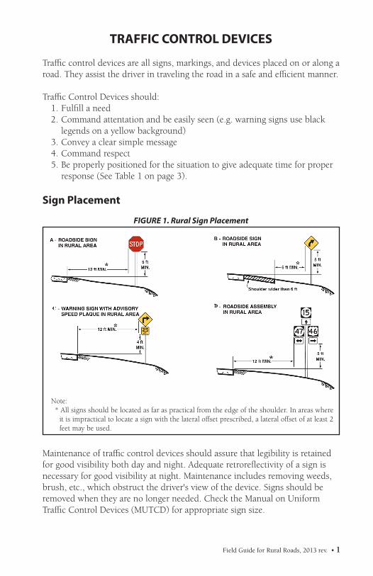
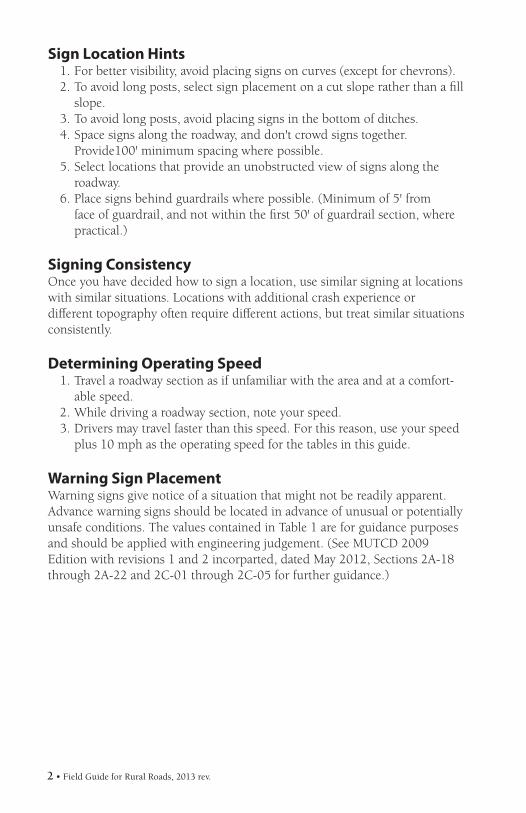
Sign Placement
Maintenance of traffic control devices should assure that legibility is retained for good visibility both day and night. Adequate retroreflectivity of a sign is necessary for good visibility at night. Maintenance includes removing weeds, brush, etc., which obstruct the driver's view of the device. Signs should beremoved when they are no longer needed. Check the Manual on UniformTraffic Control Devices (MUTCD) for appropriate sign size.
FIGURE 1. Rural Sign Placement
Note: * All signs should be located as far as practical from the edge of the shoulder. In areas where
it is impractical to locate a sign with the lateral offset prescribed, a lateral offset of at least 2 feet may be used.
2 • Field Guide for Rural Roads, 2013 rev.
Sign Location Hints1. For better visibility, avoid placing signs on curves (except for chevrons).2. To avoid long posts, select sign placement on a cut slope rather than a fill
slope.3. To avoid long posts, avoid placing signs in the bottom of ditches.4. Space signs along the roadway, and don't crowd signs together.
Provide100' minimum spacing where possible.5. Select locations that provide an unobstructed view of signs along the
roadway.6. Place signs behind guardrails where possible. (Minimum of 5' from
face of guardrail, and not within the first 50' of guardrail section, where practical.)
Signing ConsistencyOnce you have decided how to sign a location, use similar signing at locationswith similar situations. Locations with additional crash experience ordifferent topography often require different actions, but treat similar situationsconsistently.
Determining Operating Speed1. Travel a roadway section as if unfamiliar with the area and at a comfort-
able speed.2. While driving a roadway section, note your speed.3. Drivers may travel faster than this speed. For this reason, use your speed
plus 10 mph as the operating speed for the tables in this guide.
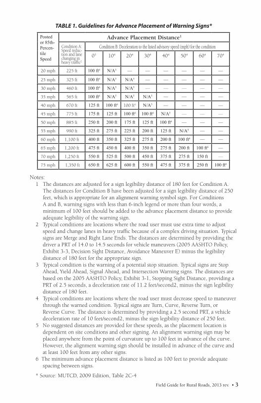
Warning Sign PlacementWarning signs give notice of a situation that might not be readily apparent.Advance warning signs should be located in advance of unusual or potentiallyunsafe conditions. The values contained in Table 1 are for guidance purposes and should be applied with engineering judgement. (See MUTCD 2009 Edition with revisions 1 and 2 incorparted, dated May 2012, Sections 2A-18 through 2A-22 and 2C-01 through 2C-05 for further guidance.)
Field Guide for Rural Roads, 2013 rev. • 3
Notes: 1 The distances are adjusted for a sign legibility distance of 180 feet for Condition A.
The distances for Condition B have been adjusted for a sign legibility distance of 250 feet, which is appropriate for an alignment warning symbol sign. For Conditions A and B, warning signs with less than 6-inch legend or more than four words, a minimum of 100 feet should be added to the advance placement distance to provide adequate legibility of the warning sign.
2 Typical conditions are locations where the road user must use extra time to adjust speed and change lanes in heavy traffic because of a complex driving situation. Typical signs are Merge and Right Lane Ends. The distances are determined by providing the driver a PRT of 14.0 to 14.5 seconds for vehicle maneuvers (2005 AASHTO Policy, Exhibit 3-3, Decision Sight Distance, Avoidance Maneuver E) minus the legibility distance of 180 feet for the appropriate sign.
3 Typical condition is the warning of a potential stop situation. Typical signs are Stop Ahead, Yield Ahead, Signal Ahead, and Intersection Warning signs. The distances are based on the 2005 AASHTO Policy, Exhibit 3-1, Stopping Sight Distance, providing a PRT of 2.5 seconds, a deceleration rate of 11.2 feet/second2, minus the sign legibility distance of 180 feet.
4 Typical conditions are locations where the road user must decrease speed to maneuver through the warned condition. Typical signs are Turn, Curve, Reverse Turn, or Reverse Curve. The distance is determined by providing a 2.5 second PRT, a vehicle deceleration rate of 10 feet/second2, minus the sign legibility distance of 250 feet.
5 No suggested distances are provided for these speeds, as the placement location is dependent on site conditions and other signing. An alignment warning sign may be placed anywhere from the point of curvature up to 100 feet in advance of the curve. However, the alignment warning sign should be installed in advance of the curve and at least 100 feet from any other signs.
6 The minimum advance placement distance is listed as 100 feet to provide adequate spacing between signs.
* Source: MUTCD, 2009 Edition, Table 2C-4
TABLE 1. Guidelines for Advance Placement of Warning Signs*
Postedor 85th-Percen-tileSpeed
Advance Placement Distance1
Condition A: Speed reduc-tion and lane changing in heavy traffic2
Condition B: Deceleration to the listed advisory speed (mph) for the condition
03 104 204 304 404 504 604 704
20 mph 225 ft 100 ft6 N/A5 — — — — — —
25 mph 325 ft 100 ft6 N/A5 N/A5 — — — — —
30 mph 460 ft 100 ft6 N/A5 N/A5 — — — — —
35 mph 565 ft 100 ft6 N/A5 N/A5 N/A5 — — — —
40 mph 670 ft 125 ft 100 ft6 100 ft6 N/A5 — — — —
45 mph 775 ft 175 ft 125 ft 100 ft6 100 ft6 N/A5 — — —
50 mph 885 ft 250 ft 200 ft 175 ft 125 ft 100 ft6 — — —
55 mph 990 ft 325 ft 275 ft 225 ft 200 ft 125 ft N/A5 — —
60 mph 1,100 ft 400 ft 350 ft 325 ft 275 ft 200 ft 100 ft6 — —
65 mph 1,200 ft 475 ft 450 ft 400 ft 350 ft 275 ft 200 ft 100 ft6 —
70 mph 1,250 ft 550 ft 525 ft 500 ft 450 ft 375 ft 275 ft 150 ft —
75 mph 1,350 ft 650 ft 625 ft 600 ft 550 ft 475 ft 375 ft 250 ft 100 ft6
4 • Field Guide for Rural Roads, 2013 rev.
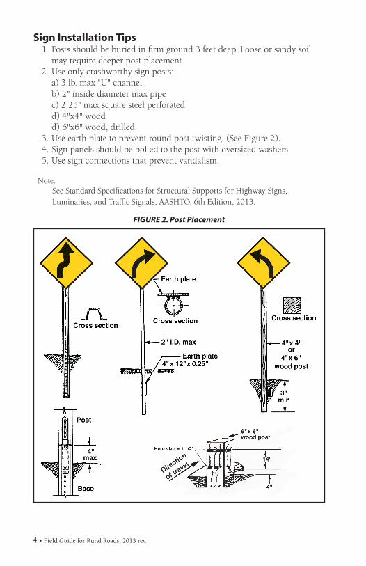
FIGURE 2. Post Placement
Sign Installation Tips1. Posts should be buried in firm ground 3 feet deep. Loose or sandy soil
may require deeper post placement.2. Use only crashworthy sign posts: a) 3 lb. max "U" channel b) 2" inside diameter max pipe c) 2.25" max square steel perforated d) 4"x4" wood d) 6"x6" wood, drilled.3. Use earth plate to prevent round post twisting. (See Figure 2).4. Sign panels should be bolted to the post with oversized washers.5. Use sign connections that prevent vandalism.
Note: See Standard Specifications for Structural Supports for Highway Signs,
Luminaries, and Traffic Signals, AASHTO, 6th Edition, 2013.
Field Guide for Rural Roads, 2013 rev. • 5
RAILROAD CROSSINGS
Crashes involving railroads are severe and often result in fatalities.Adequate sight distance and signing are important.
1. Crossbuck (R15-1) signs shall be used on each approach at all railroad crossings. A white retroreflective strip (width >= 2 in) should be used on the back of each blade of each Crossbuck sign for the length of each blade. If automatic gates are not present and if there are 2 or more tracks at a grade crossing, the number of tracks shall be indicated on a supplemental Number of Tracks (R15-2P) Plaque of inverted T shape mounted below the Crossbuck sign. (See MUTCD 2009 Edition, Section 8B-03 for further guidance.)1
2. A YIELD (R1-2) or STOP (R1-1) sign shall be installed on either the Crossbuck sign support or on a separate support. (See Figure 3 and MUTCD 2009 Edition, Section 8B-04 for further guidence.)2
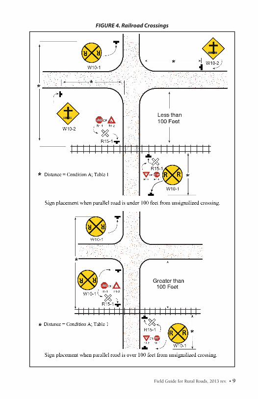
3. A Grade Crossing Advance Warning (W10-1) sign should be used at all railroad crossings. (See Figure 4 and MUTCD 2009 Edition, Section 8B-06 for further guidance.)
4. Vegetation should be removed to improve the sight distance at the railroad crossing.
5. The roadway approach grade to the railroad crossing should be flat enough to prevent truck snagging.
Notes: 1. K.S.A. 66-2, 121 requires railway corporations to erect crossbucks. 2. STOP or YIELD signs may be responsibility of the railway corporations.
6 • Field Guide for Rural Roads, 2013 rev.
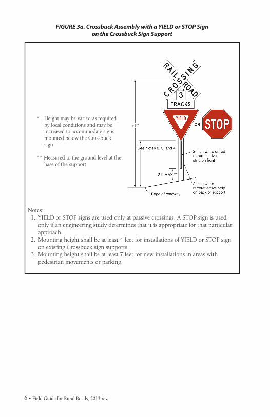
Notes:1. YIELD or STOP signs are used only at passive crossings. A STOP sign is used
only if an engineering study determines that it is appropriate for that particular approach.
2. Mounting height shall be at least 4 feet for installations of YIELD or STOP sign on existing Crossbuck sign supports.3. Mounting height shall be at least 7 feet for new installations in areas with
pedestrian movements or parking.
* Height may be varied as required by local conditions and may be increased to accommodate signs mounted below the Crossbuck sign
** Measured to the ground level at the base of the support
FIGURE 3a. Crossbuck Assembly with a YIELD or STOP Signon the Crossbuck Sign Support
Field Guide for Rural Roads, 2013 rev. • 7
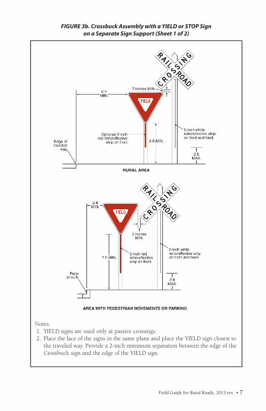
Notes:1. YIELD signs are used only at passive crossings.2. Place the face of the signs in the same plane and place the YIELD sign closest to
the traveled way. Provide a 2-inch minimum separation between the edge of the Crossbuck sign and the edge of the YIELD sign.
FIGURE 3b. Crossbuck Assembly with a YIELD or STOP Signon a Separate Sign Support (Sheet 1 of 2)
8 • Field Guide for Rural Roads, 2013 rev.
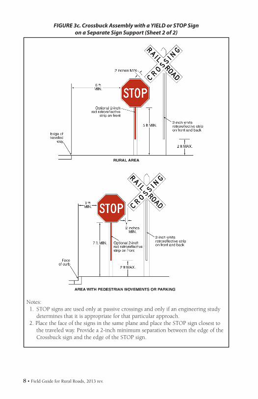
Notes:1. STOP signs are used only at passive crossings and only if an engineering study
determines that it is appropriate for that particular approach.2. Place the face of the signs in the same plane and place the STOP sign closest to
the traveled way. Provide a 2-inch minimum separation between the edge of the Crossbuck sign and the edge of the STOP sign.
FIGURE 3c. Crossbuck Assembly with a YIELD or STOP Signon a Separate Sign Support (Sheet 2 of 2)
Field Guide for Rural Roads, 2013 rev. • 9
FIGURE 4. Railroad Crossings
10 • Field Guide for Rural Roads, 2013 rev.
HORIZONTAL CURVES
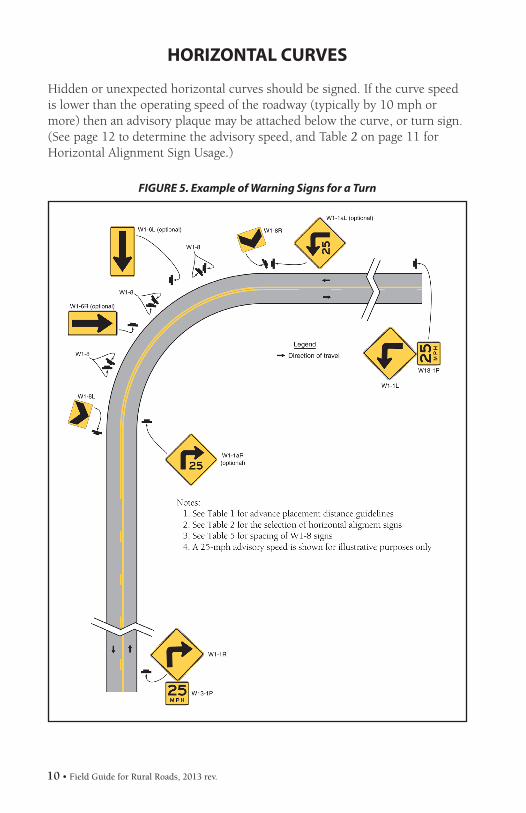
Hidden or unexpected horizontal curves should be signed. If the curve speed is lower than the operating speed of the roadway (typically by 10 mph or more) then an advisory plaque may be attached below the curve, or turn sign. (See page 12 to determine the advisory speed, and Table 2 on page 11 for Horizontal Alignment Sign Usage.)
FIGURE 5. Example of Warning Signs for a Turn
Field Guide for Rural Roads, 2013 rev. • 11
In rolling or mountainous terrain, crests of vertical curves often limit sight distance. Where this is the case, check that the roadway width is maintained over the crest, i.e., there is no narrowing of the roadway. You may want to consider posting a cross road warning sign if there is an access location close to the crest of the curve.
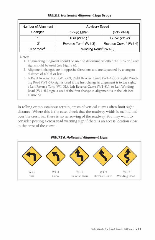
TABLE 2. Horizontal Alignment Sign Usage
FIGURE 6. Holizontal Alignment Signs
Notes:1. Engineering judgment should be used to determine whether the Turn or Curve
sign should be used (see Figure 6).2. Alignment changes are in opposite directions and are separated by a tangent
distance of 600 ft or less.3. A Right Reverse Turn (W1-3R), Right Reverse Curve (W1-4R), or Right Wind-
ing Road (W1-5R) sign is used if the first change in alignment is to the right; a Left Reverse Turn (W1-3L), Left Reverse Curve (W1-4L), or Left Winding Road (W1-5L) sign is used if the first change in alignment is to the left (see Figure 6).
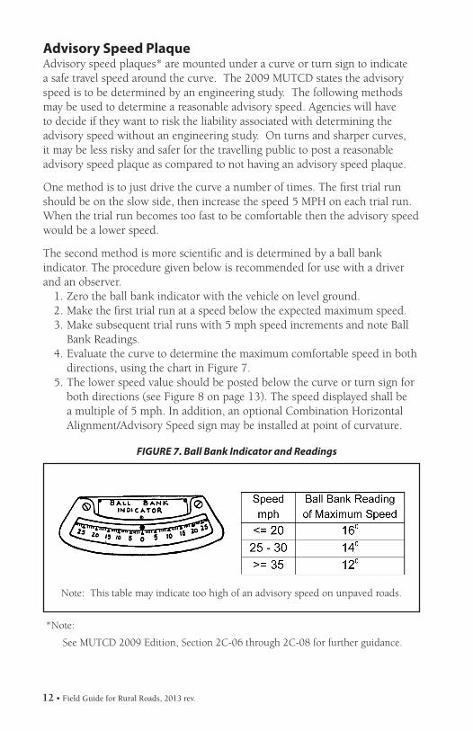
Note: This table may indicate too high of an advisory speed on unpaved roads.
*Note:
See MUTCD 2009 Edition, Section 2C-06 through 2C-08 for further guidance.
FIGURE 7. Ball Bank Indicator and Readings
Advisory Speed Plaque Advisory speed plaques* are mounted under a curve or turn sign to indicate a safe travel speed around the curve. The 2009 MUTCD states the advisory speed is to be determined by an engineering study. The following methods may be used to determine a reasonable advisory speed. Agencies will have to decide if they want to risk the liability associated with determining the advisory speed without an engineering study. On turns and sharper curves, it may be less risky and safer for the travelling public to post a reasonable advisory speed plaque as compared to not having an advisory speed plaque.
One method is to just drive the curve a number of times. The first trial run should be on the slow side, then increase the speed 5 MPH on each trial run. When the trial run becomes too fast to be comfortable then the advisory speed would be a lower speed.
The second method is more scientific and is determined by a ball bank indicator. The procedure given below is recommended for use with a driver and an observer.
1. Zero the ball bank indicator with the vehicle on level ground.2. Make the first trial run at a speed below the expected maximum speed.3. Make subsequent trial runs with 5 mph speed increments and note Ball
Bank Readings.4. Evaluate the curve to determine the maximum comfortable speed in both
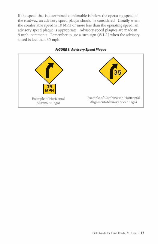
directions, using the chart in Figure 7.5. The lower speed value should be posted below the curve or turn sign for
both directions (see Figure 8 on page 13). The speed displayed shall be a multiple of 5 mph. In addition, an optional Combination Horizontal Alignment/Advisory Speed sign may be installed at point of curvature.
Field Guide for Rural Roads, 2013 rev. • 13
Example of Horizontal Alignment Signs
FIGURE 8. Advisory Speed Plaque
Example of Combination Horizontal Alignment/Advisory Speed Signs
If the speed that is determined comfortable is below the operating speed of the roadway, an advisory speed plaque should be considered. Usually when the comfortable speed is 10 MPH or more less than the operating speed, an advisory speed plaque is appropriate. Advisory speed plaques are made in 5 mph increments. Remember to use a turn sign (W1-1) when the advisory speed is less than 35 mph.
14 • Field Guide for Rural Roads, 2013 rev.
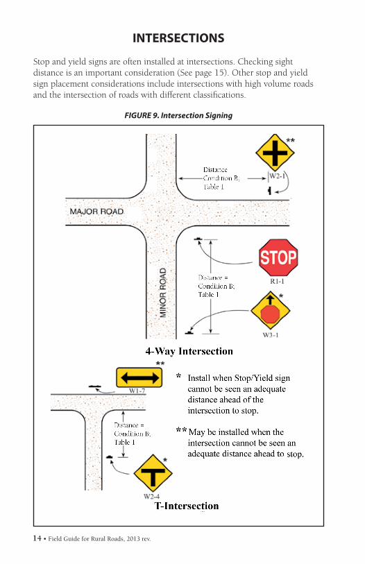
FIGURE 9. Intersection Signing
INTERSECTIONS
Stop and yield signs are often installed at intersections. Checking sight distance is an important consideration (See page 15). Other stop and yield sign placement considerations include intersections with high volume roads and the intersection of roads with different classifications.
Field Guide for Rural Roads, 2013 rev. • 15
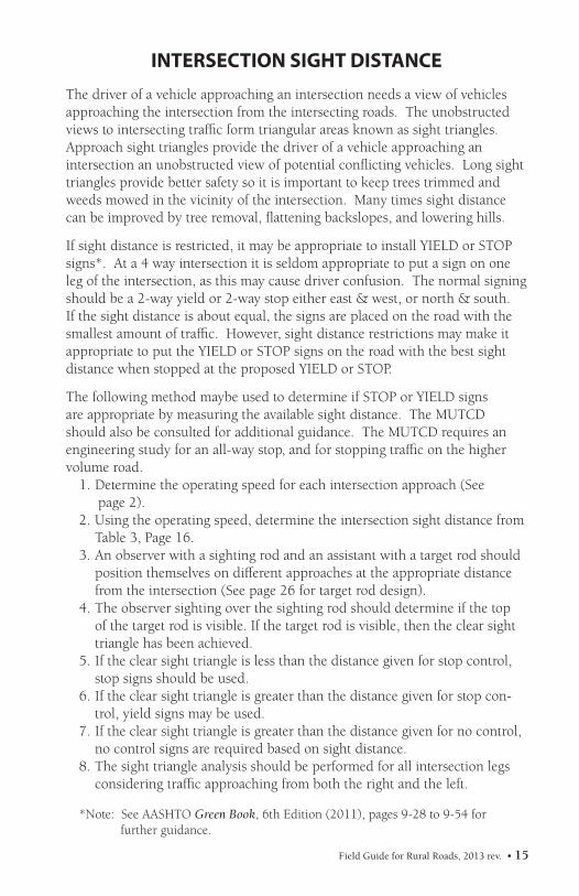
INTERSECTION SIGHT DISTANCEThe driver of a vehicle approaching an intersection needs a view of vehicles approaching the intersection from the intersecting roads. The unobstructed views to intersecting traffic form triangular areas known as sight triangles. Approach sight triangles provide the driver of a vehicle approaching an intersection an unobstructed view of potential conflicting vehicles. Long sight triangles provide better safety so it is important to keep trees trimmed and weeds mowed in the vicinity of the intersection. Many times sight distance can be improved by tree removal, flattening backslopes, and lowering hills.
If sight distance is restricted, it may be appropriate to install YIELD or STOP signs*. At a 4 way intersection it is seldom appropriate to put a sign on one leg of the intersection, as this may cause driver confusion. The normal signing should be a 2-way yield or 2-way stop either east & west, or north & south. If the sight distance is about equal, the signs are placed on the road with the smallest amount of traffic. However, sight distance restrictions may make it appropriate to put the YIELD or STOP signs on the road with the best sight distance when stopped at the proposed YIELD or STOP.
The following method maybe used to determine if STOP or YIELD signs are appropriate by measuring the available sight distance. The MUTCD should also be consulted for additional guidance. The MUTCD requires an engineering study for an all-way stop, and for stopping traffic on the higher volume road.
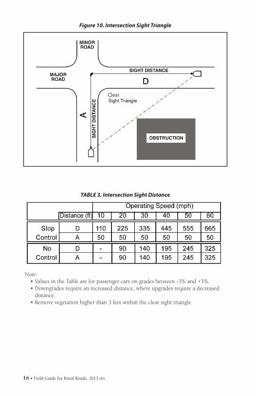
1. Determine the operating speed for each intersection approach (See page 2).2. Using the operating speed, determine the intersection sight distance from
Table 3, Page 16.3. An observer with a sighting rod and an assistant with a target rod should
position themselves on different approaches at the appropriate distance from the intersection (See page 26 for target rod design).
4. The observer sighting over the sighting rod should determine if the top of the target rod is visible. If the target rod is visible, then the clear sight triangle has been achieved.
5. If the clear sight triangle is less than the distance given for stop control, stop signs should be used.
6. If the clear sight triangle is greater than the distance given for stop con-trol, yield signs may be used.
7. If the clear sight triangle is greater than the distance given for no control, no control signs are required based on sight distance.
8. The sight triangle analysis should be performed for all intersection legs considering traffic approaching from both the right and the left.
*Note: See AASHTO Green Book, 6th Edition (2011), pages 9-28 to 9-54 for further guidance.
16 • Field Guide for Rural Roads, 2013 rev.
Note: • Values in the Table are for passenger cars on grades between -3% and +3%.• Downgrades require an increased distance, where upgrades require a decreased distance.• Remove vegetation higher than 3 feet within the clear sight triangle.
Figure 10. Intersection Sight Triangle
TABLE 3. Intersection Sight Distance
Field Guide for Rural Roads, 2013 rev. • 17
DELINEATION
Post mounted delineation may be used to outline the edge of the travelway. Potential locations for delineators are:
1. Confusing horizontal alignment;2. Sharp or unexpected curves;3. Curves or turns at the end of long, straight road sections; and4. At transitions before narrow bridges and culverts.
Delineators should be placed at a constant offset from the edge of shoulder (typically between 2 feet and 8 feet). When delineating an obstruction where the road narrows, the line of delineation should make a smooth transition to the inside of the obstruction. When delineators are used with a guardrail or other longitudinal barriers, they should be attached to or placed just behind the guardrail or longitudinal barrier.
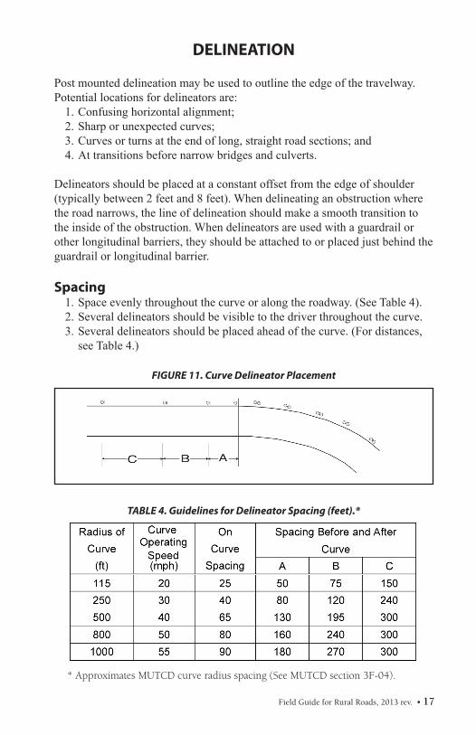
Spacing1. Space evenly throughout the curve or along the roadway. (See Table 4).2. Several delineators should be visible to the driver throughout the curve.3. Several delineators should be placed ahead of the curve. (For distances,
see Table 4.)
FIGURE 11. Curve Delineator Placement
TABLE 4. Guidelines for Delineator Spacing (feet).*
* Approximates MUTCD curve radius spacing (See MUTCD section 3F-04).
18 • Field Guide for Rural Roads, 2013 rev.
Advisory Speed Curve Radius Sign Spacing
15 mph or less Less than 200 feet 40 feet
20 to 30 mph 200 to 400 feet 80 feet
35 to 45 mph 401 to 700 feet 120 feet
50 to 60 mph 701 to 1,250 feet 160 feet
More than 60 mph More than 1,250 feet 200 feet
Note: The relationship between the curve radius and the advisory speed shown in this table should not be used to determine the adivsory speed.
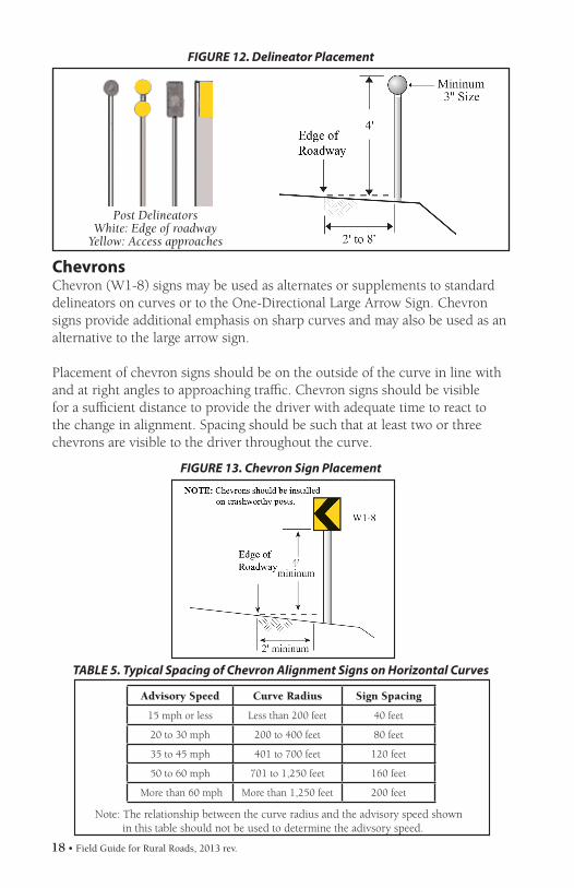
ChevronsChevron (W1-8) signs may be used as alternates or supplements to standarddelineators on curves or to the One-Directional Large Arrow Sign. Chevronsigns provide additional emphasis on sharp curves and may also be used as analternative to the large arrow sign.
Placement of chevron signs should be on the outside of the curve in line withand at right angles to approaching traffic. Chevron signs should be visiblefor a sufficient distance to provide the driver with adequate time to react tothe change in alignment. Spacing should be such that at least two or threechevrons are visible to the driver throughout the curve.
FIGURE 13. Chevron Sign Placement
FIGURE 12. Delineator Placement
Post DelineatorsWhite: Edge of roadway
Yellow: Access approaches
TABLE 5. Typical Spacing of Chevron Alignment Signs on Horizontal Curves
Field Guide for Rural Roads, 2013 rev. • 19
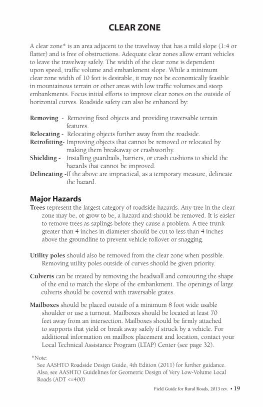
CLEAR ZONE
A clear zone* is an area adjacent to the travelway that has a mild slope (1:4 orflatter) and is free of obstructions. Adequate clear zones allow errant vehiclesto leave the travelway safely. The width of the clear zone is dependentupon speed, traffic volume and embankment slope. While a minimumclear zone width of 10 feet is desirable, it may not be economically feasiblein mountainous terrain or other areas with low traffic volumes and steepembankments. Focus initial efforts to improve clear zones on the outside ofhorizontal curves. Roadside safety can also be enhanced by:
Removing - Removing fixed objects and providing traversable terrain features.
Relocating - Relocating objects further away from the roadside.Retrofitting- Improving objects that cannot be removed or relocated by
making them breakaway or crashworthy.Shielding - Installing guardrails, barriers, or crash cushions to shield the
hazards that cannot be improved.Delineating -If the above are impractical, as a temporary measure, delineate the hazard.
Major HazardsTrees represent the largest category of roadside hazards. Any tree in the clear
zone may be, or grow to be, a hazard and should be removed. It is easierto remove trees as saplings before they cause a problem. A tree trunkgreater than 4 inches in diameter should be cut to less than 4 inches above the groundline to prevent vehicle rollover or snagging.
Utility poles should also be removed from the clear zone when possible. Removing utility poles outside of curves should be given priority.
Culverts can be treated by removing the headwall and contouring the shape of the end to match the slope of the embankment. The openings of large culverts should be covered with traversable grates.
Mailboxes should be placed outside of a minimum 8 foot wide usable shoulder or use a turnout. Mailboxes should be located at least 70 feet away from an intersection. Mailboxes should be firmly attached to supports that yield or break away safely if struck by a vehicle. For additional information on mailbox placement and location, contact your Local Technical Assistance Program (LTAP) Center (see page 32).
*Note:See AASHTO Roadside Design Guide, 4th Edition (2011) for further guidance.Also, see AASHTO Guidelines for Geometric Design of Very Low-Volume Local Roads (ADT <=400)
20 • Field Guide for Rural Roads, 2013 rev.
BRIDGES AND CULVERTS
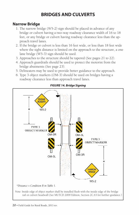
Narrow Bridge1. The narrow bridge (W5-2) sign should be placed in advance of any
bridge or culvert having a two-way roadway clearance width of 16 to 18 feet, or any bridge or culvert having roadway clearance less than the ap-proach travel lanes.
2. If the bridge or culvert is less than 16 feet wide, or less than 18 feet wide where the sight distance is limited on the approach to the structure, a one lane bridge (W5-3) sign should be used.
3. Approaches to the structure should be tapered (See pages 21 to 22).4. Approach guardrails should be used to protect the motorist from the
bridge abutments (See page 23).5. Delineators may be used to provide better guidance to the approach.6. Type 3 object markers (OM-3) should be used on bridges having a
roadway clearance less than approach travel lanes.
*Distance = Condition B in Table 1.
Note: Inside edge of object marker shall be installed flush with the inside edge of the bridge rail or culvert headwall (See MUTCD 2009 Edition, Section 2C.63 for further guidance.)
FIGURE 14. Bridge Signing
Field Guide for Rural Roads, 2013 rev. • 21
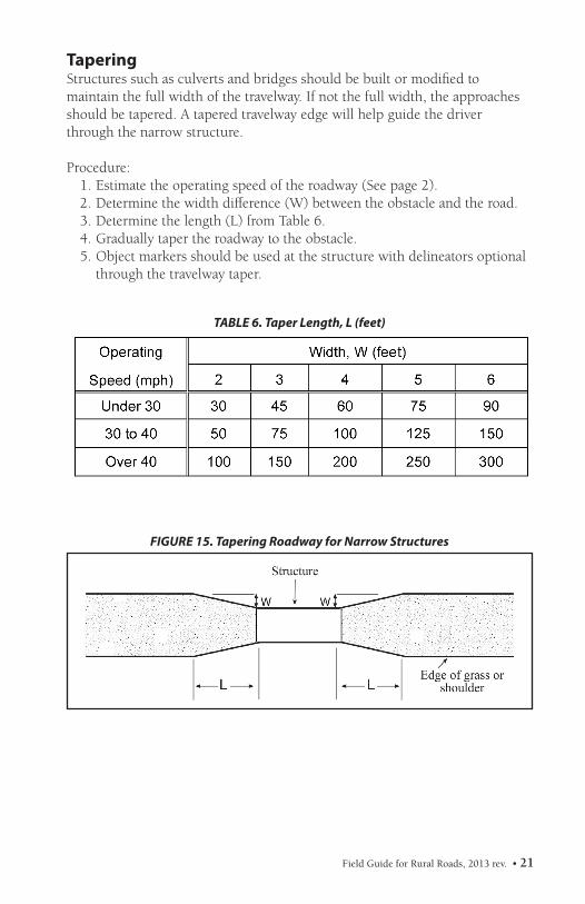
TaperingStructures such as culverts and bridges should be built or modified to maintain the full width of the travelway. If not the full width, the approaches should be tapered. A tapered travelway edge will help guide the driver through the narrow structure.
Procedure:1. Estimate the operating speed of the roadway (See page 2).2. Determine the width difference (W) between the obstacle and the road.3. Determine the length (L) from Table 6.4. Gradually taper the roadway to the obstacle.5. Object markers should be used at the structure with delineators optional
through the travelway taper.
FIGURE 15. Tapering Roadway for Narrow Structures
TABLE 6. Taper Length, L (feet)
22 • Field Guide for Rural Roads, 2013 rev.
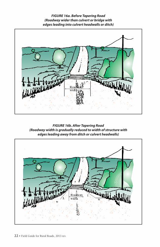
FIGURE 16a. Before Tapering Road(Roadway wider than culvert or bridge with
edges leading into culvert headwalls or ditch)
FIGURE 16b. After Tapering Road(Roadway width is gradually reduced to width of structure with
edges leading away from ditch or culvert headwalls)
Field Guide for Rural Roads, 2013 rev. • 23
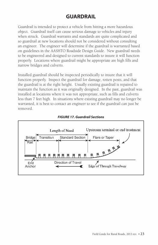
GUARDRAIL
Guardrail is intended to protect a vehicle from hitting a more hazardous object. Guardrail itself can cause serious damage to vehicles and injury when struck. Guardrail warrants and standards are quite complicated and so guardrail at new locations should not be considered without consulting an engineer. The engineer will determine if the guardrail is warranted based on guidelines in the AASHTO Roadside Design Guide. New guardrail needs to be engineered and designed to current standards to insure it will function properly. Locations where guardrail might be appropriate are high fills and narrow bridges and culverts.
Installed guardrail should be inspected periodically to insure that it will function properly. Inspect the guardrail for damage, rotten posts, and that the guardrail is at the right height. Usually existing guardrail is repaired to maintain the function as it was originally designed. In the past, guardrail was installed at locations where it was not appropriate, such as fills and culverts less than 7 feet high. In situations where existing guardrail may no longer be warranted, it is best to contact an engineer to see if the guardrail can just be removed.
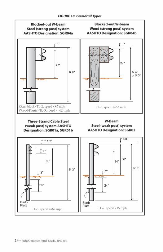
Three-Strand Cable Steel (weak post) system AASHTO
Designation: SGR01a, SGR01b
W-BeamSteel (weak post) system
AASHTO Designation: SGR02
FIGURE 18. Guardrail Types
TL-3, speed <=62 mph
TL-3, speed <=62 mph TL-2, speed <45 mph
Field Guide for Rural Roads, 2013 rev. • 25
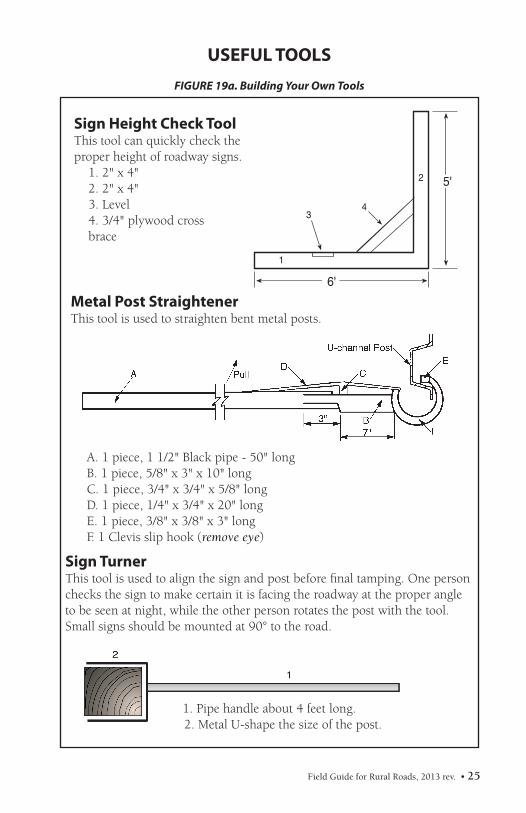
FIGURE 19a. Building Your Own Tools
USEFUL TOOLS
Sign Height Check ToolThis tool can quickly check theproper height of roadway signs.
1. 2" x 4"2. 2" x 4"3. Level4. 3/4" plywood crossbrace
Metal Post StraightenerThis tool is used to straighten bent metal posts.
A. 1 piece, 1 1/2" Black pipe - 50" long B. 1 piece, 5/8" x 3" x 10" longC. 1 piece, 3/4" x 3/4" x 5/8" longD. 1 piece, 1/4" x 3/4" x 20" longE. 1 piece, 3/8" x 3/8" x 3" longF. 1 Clevis slip hook (remove eye)
Sign TurnerThis tool is used to align the sign and post before final tamping. One person checks the sign to make certain it is facing the roadway at the proper angle to be seen at night, while the other person rotates the post with the tool.Small signs should be mounted at 90° to the road.
1. Pipe handle about 4 feet long. 2. Metal U-shape the size of the post.
26 • Field Guide for Rural Roads, 2013 rev.
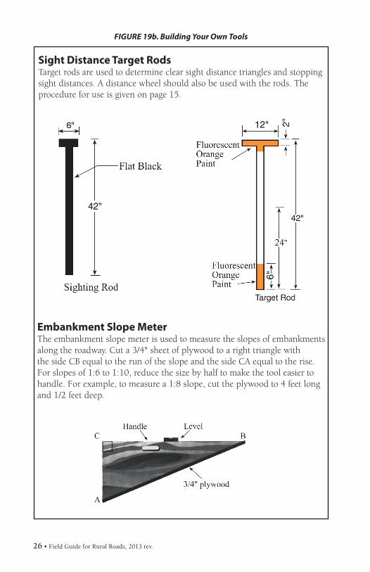
Sight Distance Target RodsTarget rods are used to determine clear sight distance triangles and stoppingsight distances. A distance wheel should also be used with the rods. Theprocedure for use is given on page 15.
Embankment Slope MeterThe embankment slope meter is used to measure the slopes of embankmentsalong the roadway. Cut a 3/4" sheet of plywood to a right triangle withthe side CB equal to the run of the slope and the side CA equal to the rise.For slopes of 1:6 to 1:10, reduce the size by half to make the tool easier tohandle. For example, to measure a 1:8 slope, cut the plywood to 4 feet long and 1/2 feet deep.
FIGURE 19b. Building Your Own Tools
Field Guide for Rural Roads, 2013 rev. • 27
ROAD SURFACE MANAGEMENT
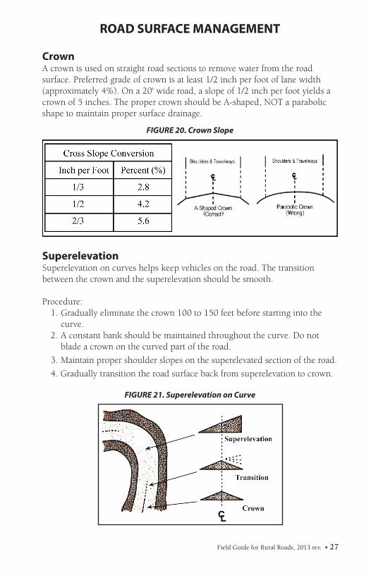
CrownA crown is used on straight road sections to remove water from the road surface. Preferred grade of crown is at least 1/2 inch per foot of lane width(approximately 4%). On a 20' wide road, a slope of 1/2 inch per foot yields acrown of 5 inches. The proper crown should be A-shaped, NOT a parabolicshape to maintain proper surface drainage.
SuperelevationSuperelevation on curves helps keep vehicles on the road. The transitionbetween the crown and the superelevation should be smooth.
Procedure:1. Gradually eliminate the crown 100 to 150 feet before starting into the
curve.2. A constant bank should be maintained throughout the curve. Do not
blade a crown on the curved part of the road.
3. Maintain proper shoulder slopes on the superelevated section of the road.
4. Gradually transition the road surface back from superelevation to crown.
FIGURE 20. Crown Slope
FIGURE 21. Superelevation on Curve
28 • Field Guide for Rural Roads, 2013 rev.
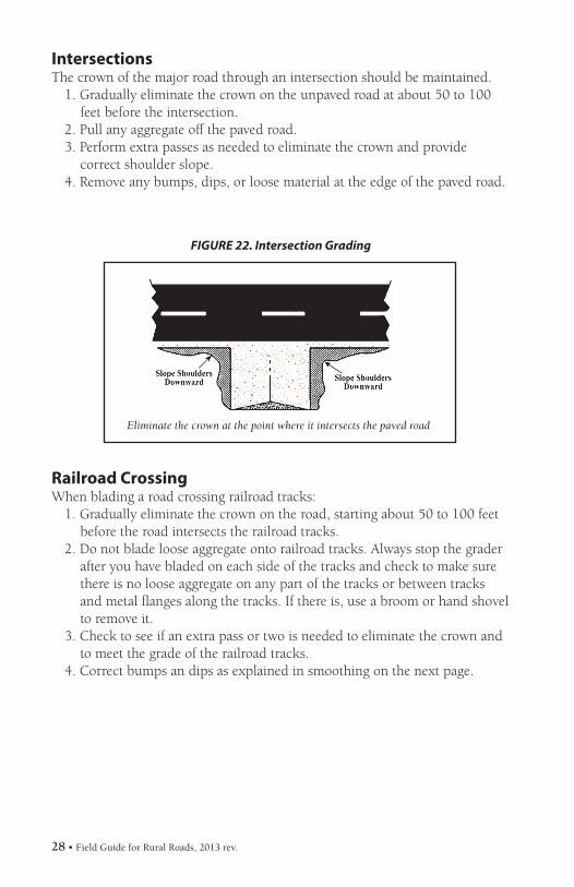
IntersectionsThe crown of the major road through an intersection should be maintained.
1. Gradually eliminate the crown on the unpaved road at about 50 to 100 feet before the intersection.
2. Pull any aggregate off the paved road.3. Perform extra passes as needed to eliminate the crown and provide
correct shoulder slope.4. Remove any bumps, dips, or loose material at the edge of the paved road.
FIGURE 22. Intersection Grading
Eliminate the crown at the point where it intersects the paved road
Railroad CrossingWhen blading a road crossing railroad tracks:
1. Gradually eliminate the crown on the road, starting about 50 to 100 feet before the road intersects the railroad tracks.
2. Do not blade loose aggregate onto railroad tracks. Always stop the grader after you have bladed on each side of the tracks and check to make sure there is no loose aggregate on any part of the tracks or between tracks and metal flanges along the tracks. If there is, use a broom or hand shovel to remove it.
3. Check to see if an extra pass or two is needed to eliminate the crown and to meet the grade of the railroad tracks.
4. Correct bumps an dips as explained in smoothing on the next page.
Field Guide for Rural Roads, 2013 rev. • 29
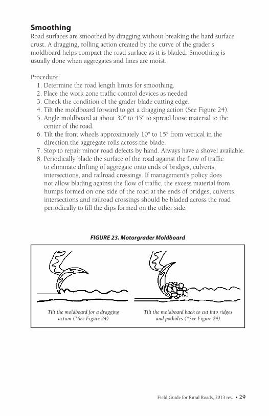
SmoothingRoad surfaces are smoothed by dragging without breaking the hard surfacecrust. A dragging, rolling action created by the curve of the grader's moldboard helps compact the road surface as it is bladed. Smoothing is usually done when aggregates and fines are moist.
Procedure:1. Determine the road length limits for smoothing.2. Place the work zone traffic control devices as needed.3. Check the condition of the grader blade cutting edge.4. Tilt the moldboard forward to get a dragging action (See Figure 24).5. Angle moldboard at about 30° to 45° to spread loose material to the
center of the road.6. Tilt the front wheels approximately 10° to 15° from vertical in the
direction the aggregate rolls across the blade.7. Stop to repair minor road defects by hand. Always have a shovel available.8. Periodically blade the surface of the road against the flow of traffic
to eliminate drifting of aggregate onto ends of bridges, culverts, intersections, and railroad crossings. If management's policy does not allow blading against the flow of traffic, the excess material from humps formed on one side of the road at the ends of bridges, culverts, intersections and railroad crossings should be bladed across the road periodically to fill the dips formed on the other side.
Tilt the moldboard for a dragging action (*See Figure 24)
Tilt the moldboard back to cut into ridgesand potholes (*See Figure 24)
FIGURE 23. Motorgrader Moldboard
30 • Field Guide for Rural Roads, 2013 rev.
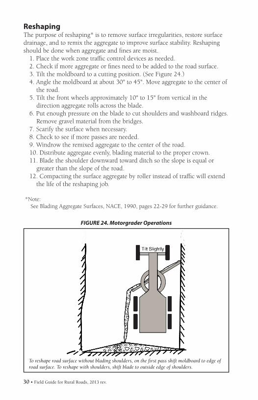
Reshaping The purpose of reshaping* is to remove surface irregularities, restore surfacedrainage, and to remix the aggregate to improve surface stability. Reshapingshould be done when aggregate and fines are moist.
1. Place the work zone traffic control devices as needed.2. Check if more aggregate or fines need to be added to the road surface.3. Tilt the moldboard to a cutting position. (See Figure 24.)4. Angle the moldboard at about 30° to 45°. Move aggregate to the center of
the road.5. Tilt the front wheels approximately 10° to 15° from vertical in the
direction aggregate rolls across the blade.6. Put enough pressure on the blade to cut shoulders and washboard ridges.
Remove gravel material from the bridges.7. Scarify the surface when necessary.8. Check to see if more passes are needed.9. Windrow the remixed aggregate to the center of the road.10. Distribute aggregate evenly, blading material to the proper crown.11. Blade the shoulder downward toward ditch so the slope is equal or
greater than the slope of the road.12. Compacting the surface aggregate by roller instead of traffic will extend
the life of the reshaping job.
*Note:See Blading Aggregate Surfaces, NACE, 1990, pages 22-29 for further guidance.
To reshape road surface without blading shoulders, on the first pass shift moldboard to edge of road surface. To reshape with shoulders, shift blade to outside edge of shoulders.
FIGURE 24. Motorgrader Operations
Field Guide for Rural Roads, 2013 rev. • 31
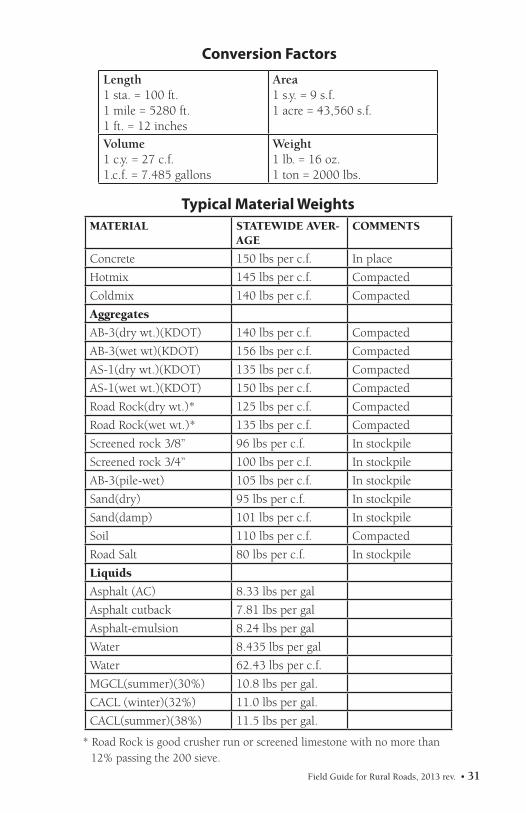
MATERIAL STATEWIDE AVER-AGE
COMMENTS
Concrete 150 lbs per c.f. In place
Hotmix 145 lbs per c.f. Compacted
Coldmix 140 lbs per c.f. Compacted
Aggregates
AB-3(dry wt.)(KDOT) 140 lbs per c.f. Compacted
AB-3(wet wt)(KDOT) 156 lbs per c.f. Compacted
AS-1(dry wt.)(KDOT) 135 lbs per c.f. Compacted
AS-1(wet wt.)(KDOT) 150 lbs per c.f. Compacted
Road Rock(dry wt.)* 125 lbs per c.f. Compacted
Road Rock(wet wt.)* 135 lbs per c.f. Compacted
Screened rock 3/8” 96 lbs per c.f. In stockpile
Screened rock 3/4” 100 lbs per c.f. In stockpile
AB-3(pile-wet) 105 lbs per c.f. In stockpile
Sand(dry) 95 lbs per c.f. In stockpile
Sand(damp) 101 lbs per c.f. In stockpile
Soil 110 lbs per c.f. Compacted
Road Salt 80 lbs per c.f. In stockpile
Liquids
Asphalt (AC) 8.33 lbs per gal
Asphalt cutback 7.81 lbs per gal
Asphalt-emulsion 8.24 lbs per gal
Water 8.435 lbs per gal
Water 62.43 lbs per c.f.
MGCL(summer)(30%) 10.8 lbs per gal.
CACL (winter)(32%) 11.0 lbs per gal.
CACL(summer)(38%) 11.5 lbs per gal.
Typical Material Weights
Conversion Factors
* Road Rock is good crusher run or screened limestone with no more than 12% passing the 200 sieve.
Training: All three of the contacts listed below provide training to local government employees at all levels.
Local Technical Assistance Program at KU (LTAP Center) Phone: 785-864-5658 FAX: 785-864-3199 http://www.ksltap.org Email: [email protected]
Rural Transportation Center at KSU Phone: 785-532-1595 FAX: 785-532-7717 http://transport.ksu.edu Email: [email protected]
Kansas Association of Counties (KAC) Phone: 785-272-2585 FAX: 785-272-3585 http://www.kansascounties.org
Other Resources:
Kansas Department of Transportation (KDOT)Dwight D. Eisenhower State Office Building 700 S.W. Harrison Street Topeka, KS 66603-3754
Bureau of Local Projects in KDOT Phone: 785-296-3861 FAX: 785-296-2079 http://www.ksdot.org/burlocalproj/
Kansas County Highway Association (KCHA) http://www.kansascountyhighway.org
National Association of County Engineers (NACE) Phone: 202-393-5041 FAX: 202-393-2630 http://www.countyengineers.org Email: [email protected]
Resources for Kansas Road Officials
Field Guide for Rural Roads, 2013 rev. • 33
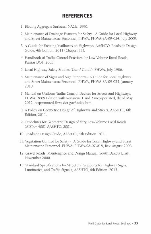
REFERENCES
1. Blading Aggregate Surfaces, NACE, 1990.
2. Maintenance of Drainage Features for Safety - A Guide for Local Highway and Street Maintenacne Personnel, FHWA, FHWA-SA-09-024, July 2009.
3. A Guide for Erecting Mailboxes on Highways, AASHTO, Roadside Design Guide, 4th Edition, 2011 (Chapter 11).
4. Handbook of Traffic Control Practices for Low Volume Rural Roads, Kansas DOT, 2005.
5. Local Highway Safety Studies (Users' Guide), FHWA, July 1986.
6. Maintenance of Signs and Sign Supports - A Guide for Local Highway and Street Maintenacne Personnel, FHWA, FHWA-SA-09-025, January 2010.
7. Manual on Uniform Traffic Control Devices for Streets and Highways, FHWA, 2009 Edition with Revisions 1 and 2 incorportated, dated May 2012. http://mutcd.fhwa.dot.gov/index.htm.
8. A Policy on Geometric Design of Highways and Streets, AASHTO, 6th Edition, 2011.
9. Guidelines for Geometric Design of Very Low-Volume Local Roads (ADT<= 400), AASHTO, 2001.
11. Vegetation Control for Safety - A Guide for Local Highway and Street Maintenacne Personnel. FHWA, FHWA-SA-07-018, Rev. August 2008.
12. Gravel Roads, Maintenance and Design Manual, South Dakota LTAP, November 2000.
13. Standard Specifications for Structural Supports for Highway Signs, Luminaries, and Traffic Signals, AASHTO, 6th Edition, 2013.
34 • Field Guide for Rural Roads, 2013 rev.
The mission of the National Local Technical Assistance
Program is to foster a safe, efficient, environmentally
sound transportation system by improving skills and
knowledge of local transportation providers through
training, technical assistance and technology transfer.
Adapted from a publication prepared by the Wyoming Technology Transfer Center in cooperation with the Wyoming Department of Transportation, March 1997. Revised by Kansas LTAP to conform with the most recent version of the Manual on Uniform Traffic Control Devices (MUTCD) in 2004 and 2013.