Geothermal Explorati Process and Production Plants Technology | Geothermal Energy 2.Geothermal Exploration Process and Production Technologies The exploration phase of a geothermal project aims at locating geothermal reservoirs for possible exploitation and at selecting the best sites for drilling production wells. Before proceeding with the specific aspects of the process, it is necessary to consider the relevance of the preliminary survey phase which involves a work program to assess the already available evidence for geothermal potential within a specific area (perhaps a country, a territory, or an island). The objectives of geothermal exploration are (Lumb, 1981): Identify geothermal phenomena. 1. Ascertain that a useful geothermal production field 2. exists. Estimate the size of the resource. 3. Determine the type (classification) of geothermal field. 4. Locate productive zones. 5. Determination the heat content of the fluids that will 6. be discharged by the wells in the geothermal field. Compilation a body of basic data against which the 7.
Transcript
Geothermal ExplorationProcess and Production Plants
Technology | Geothermal Energy
2.Geothermal Exploration Processand Production Technologies The exploration phase of a geothermal project aims at locatinggeothermal reservoirs for possible exploitation and atselecting the best sites for drilling production wells.
Before proceeding with the specific aspects of the process, itis necessary to consider the relevance of the preliminarysurvey phase which involves a work program to assess thealready available evidence for geothermal potential within aspecific area (perhaps a country, a territory, or an island).
The objectives of geothermal exploration are (Lumb, 1981):
Identify geothermal phenomena.1.Ascertain that a useful geothermal production field2.exists.Estimate the size of the resource.3.Determine the type (classification) of geothermal field.4.Locate productive zones.5.Determination the heat content of the fluids that will6.be discharged by the wells in the geothermal field.Compilation a body of basic data against which the7.
results of future monitoring can be viewed.Determination the pre-exploitation values of8.environmentally sensitive parameters.To acquire knowledge of any characteristics that might9.cause problems during field development
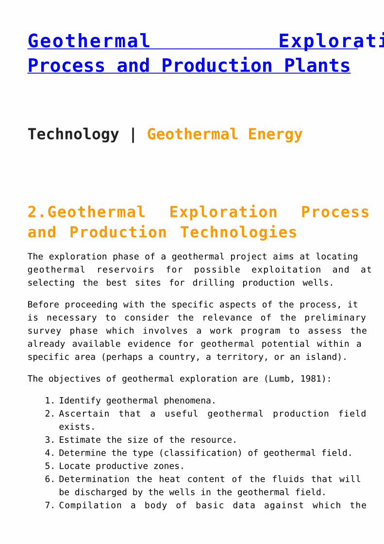
Fig.1 – Timeline for a well planned and effective surveyingand exploration work program in a geothermal project
Exploration typically begins with gathering data from existingnearby wells and other surface manifestations, and goes on tosurface and sub-surface surveying using geological,geochemical, and geophysical methods.
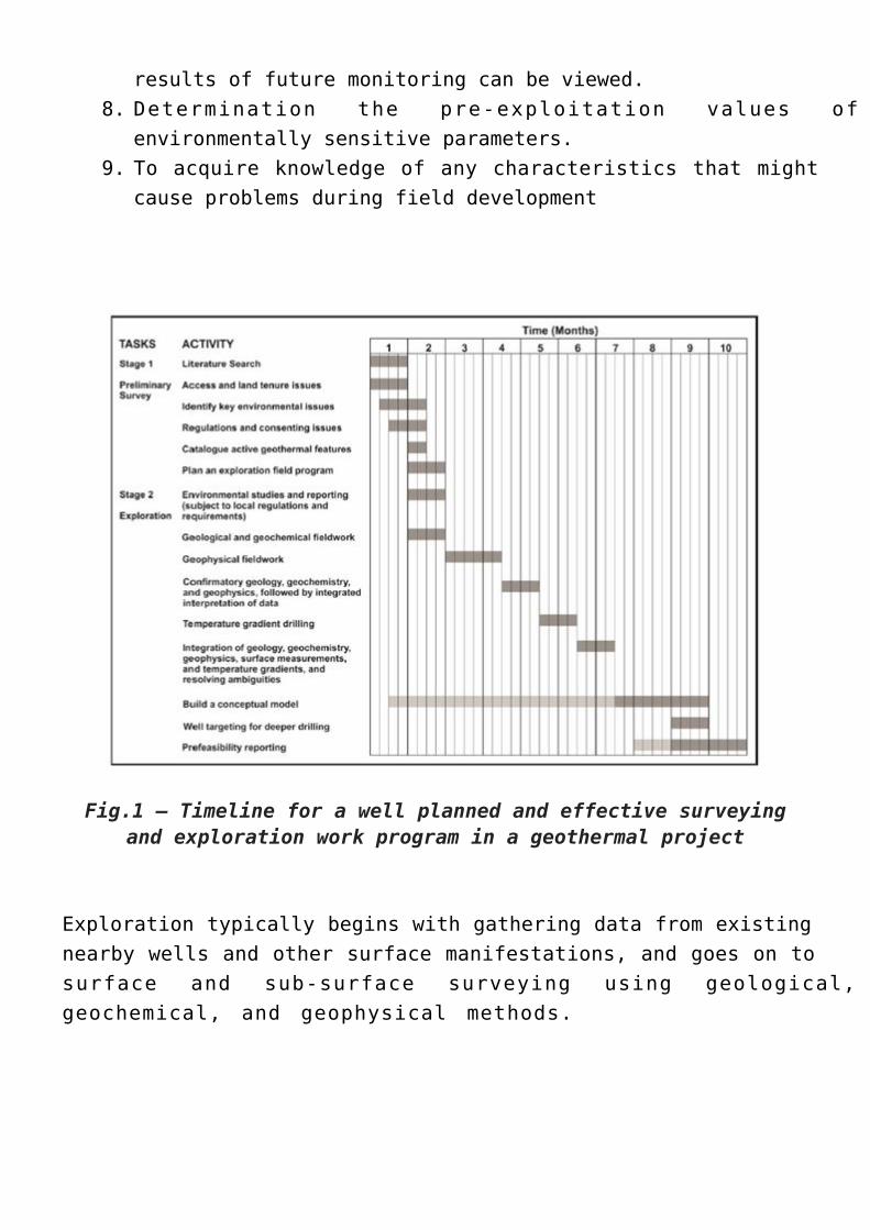
Table 1 – Surveying techniques used in the geothermalexploration
A decision to move to temperature gradient (or slim hole)drilling (defined and discussed later) may be recommendedafter the geological, geochemical and geophysical surveys havebeen completed.
When sufficient exploration data have been collected andanalyzed, then selection sites and targets for the first fewdeep exploration wells maybe defined.
In general, the most common and applied disciplines withrelative techniques are
geologygeophysicsgeochemistrydrilling technology
2.1 GeologyA thorough understanding of the geology of the project areaand how it fits into the surrounding regional geological andtectonic setting is crucial to understanding a givengeothermal system.
Initial geological studies are focused on understanding theoverall geology of the project area and identifying the most
promising areas for more detailed exploration.
Later, efforts are focused on the most promising areas withthe specific goal of understanding the permeability pathwaysthat bring thermal fluids from their deep source to shallowerparts of the system, where they can be economically exploitedfor geothermal power production.
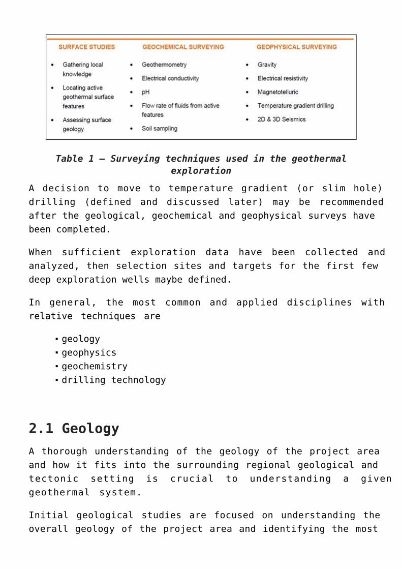
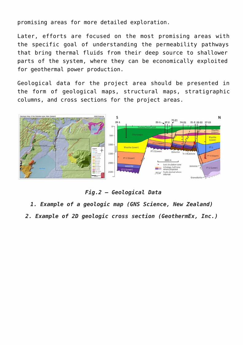
Geological data for the project area should be presented inthe form of geological maps, structural maps, stratigraphiccolumns, and cross sections for the project areas.
Fig.2 – Geological Data
1. Example of a geologic map (GNS Science, New Zealand)
2. Example of 2D geologic cross section (GeothermEx, Inc.)
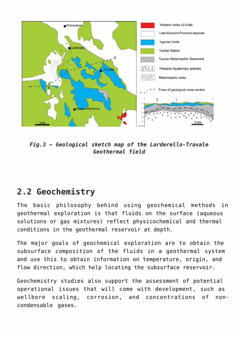
Fig.3 – Geological sketch map of the Larderello-TravaleGeothermal field
2.2 GeochemistryThe basic philosophy behind using geochemical methods ingeothermal exploration is that fluids on the surface (aqueoussolutions or gas mixtures) reflect physicochemical and thermalconditions in the geothermal reservoir at depth.
The major goals of geochemical exploration are to obtain thesubsurface composition of the fluids in a geothermal systemand use this to obtain information on temperature, origin, andflow direction, which help locating the subsurface reservoir.
Geochemistry studies also support the assessment of potentialoperational issues that will come with development, such aswellbore scaling, corrosion, and concentrations of non-condensable gases.
In the exploratory phase the task of geochemistry is mainlyto:
Estimate subsurface temperatures by using chemical andisotope geothermometers as well as mixing modelsIdentify the origin of the geothermal fluid, mainly withisotopic techniquesDefine chemical properties of the fluid with respect toenvironmental issues, scaling …Provide data to a conceptual model of the geothermalsystem
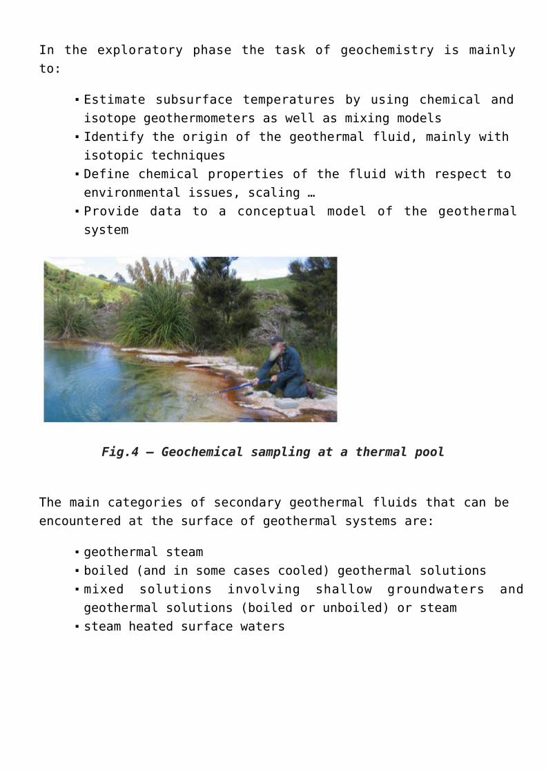
Fig.4 – Geochemical sampling at a thermal pool
The main categories of secondary geothermal fluids that can beencountered at the surface of geothermal systems are:
geothermal steamboiled (and in some cases cooled) geothermal solutionsmixed solutions involving shallow groundwaters andgeothermal solutions (boiled or unboiled) or steamsteam heated surface waters
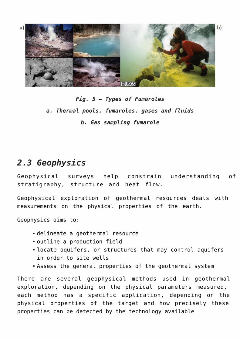
Fig. 5 – Types of Fumaroles
a. Thermal pools, fumaroles, gases and fluids
b. Gas sampling fumarole
2.3 GeophysicsGeophysical surveys help constrain understanding ofstratigraphy, structure and heat flow.
Geophysical exploration of geothermal resources deals withmeasurements on the physical properties of the earth.
Geophysics aims to:
delineate a geothermal resourceoutline a production fieldlocate aquifers, or structures that may control aquifersin order to site wellsAssess the general properties of the geothermal system
There are several geophysical methods used in geothermalexploration, depending on the physical parameters measured,each method has a specific application, depending on thephysical properties of the target and how precisely theseproperties can be detected by the technology available
2.3.1 Potential MethodsPotential method based on density and magnetic properties ofrocks and of the Earth potential fields:
Gravity methods – used to detect geologicalformations with different densities
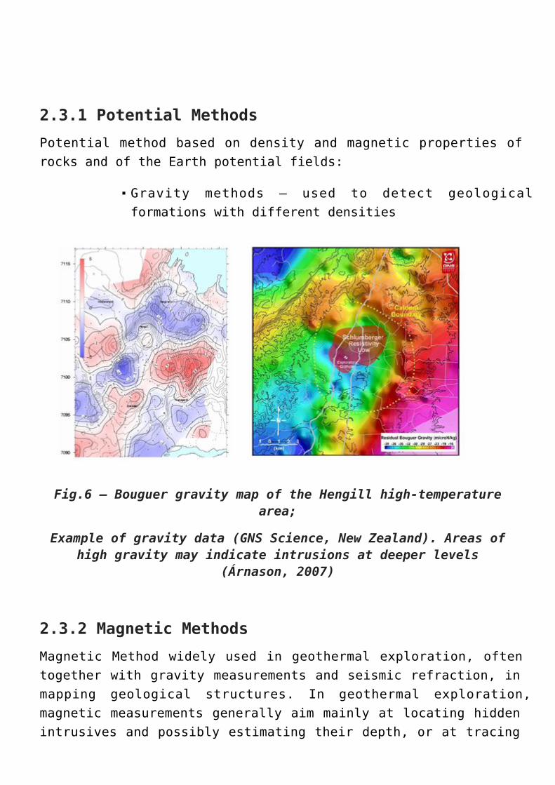
Fig.6 – Bouguer gravity map of the Hengill high-temperaturearea;
Example of gravity data (GNS Science, New Zealand). Areas ofhigh gravity may indicate intrusions at deeper levels
(Árnason, 2007)
2.3.2 Magnetic MethodsMagnetic Method widely used in geothermal exploration, oftentogether with gravity measurements and seismic refraction, inmapping geological structures. In geothermal exploration,magnetic measurements generally aim mainly at locating hiddenintrusives and possibly estimating their depth, or at tracing
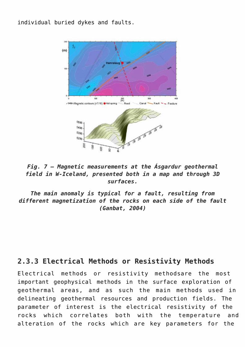
individual buried dykes and faults.
Fig. 7 – Magnetic measurements at the Ásgardur geothermalfield in W-Iceland, presented both in a map and through 3D
surfaces.
The main anomaly is typical for a fault, resulting fromdifferent magnetization of the rocks on each side of the fault
(Ganbat, 2004)
2.3.3 Electrical Methods or Resistivity MethodsElectrical methods or resistivity methods are the mostimportant geophysical methods in the surface exploration ofgeothermal areas, and as such the main methods used indelineating geothermal resources and production fields. Theparameter of interest is the electrical resistivity of therocks which correlates both with the temperature andalteration of the rocks which are key parameters for the
understanding of the geothermal systems.
Electrical methods include:
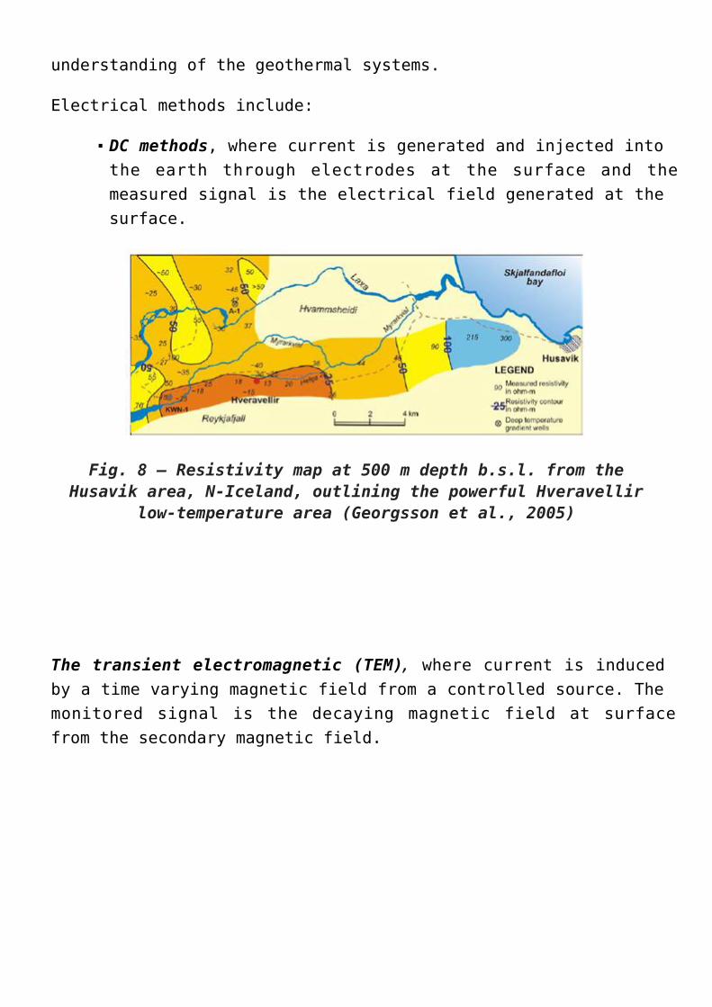
DC methods, where current is generated and injected intothe earth through electrodes at the surface and themeasured signal is the electrical field generated at thesurface.
Fig. 8 – Resistivity map at 500 m depth b.s.l. from theHusavik area, N-Iceland, outlining the powerful Hveravellir
low-temperature area (Georgsson et al., 2005)
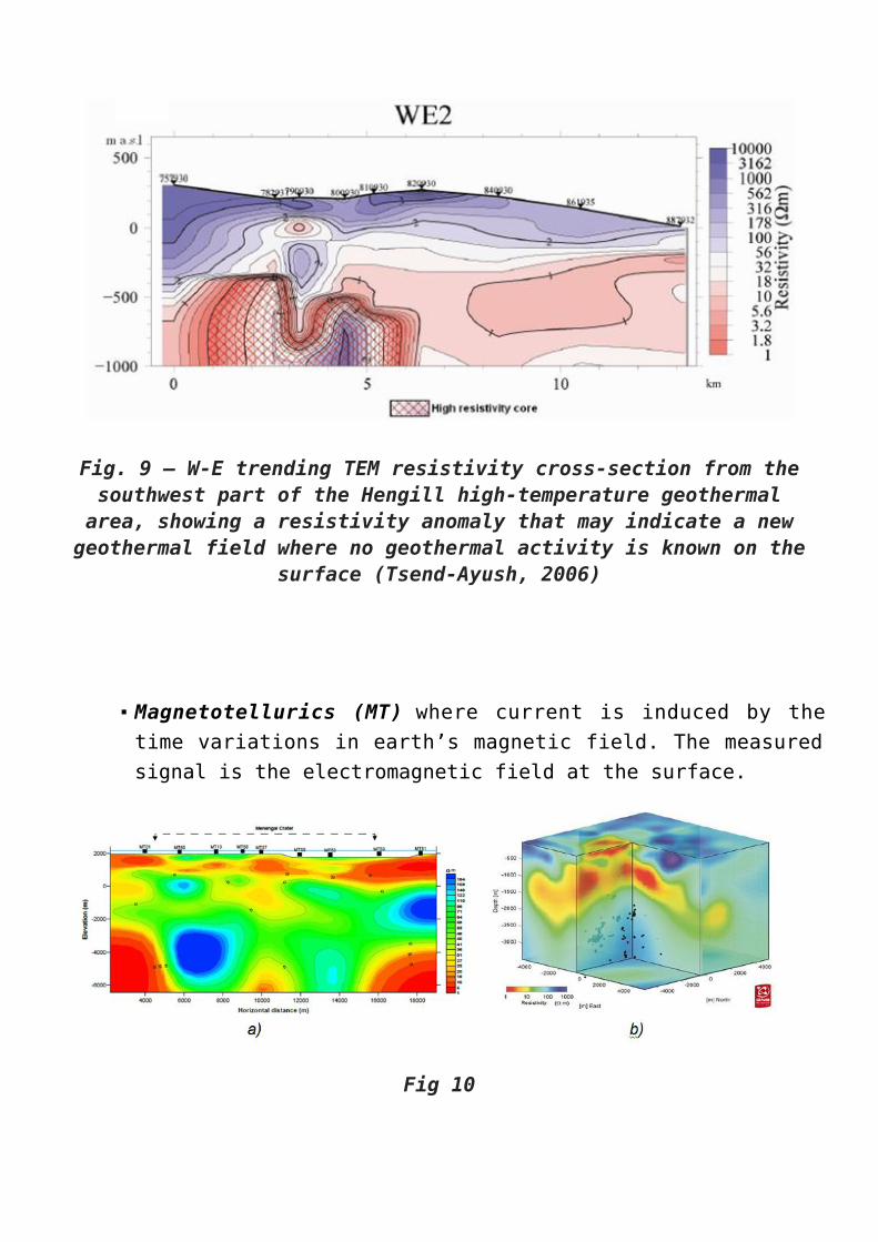
The transient electromagnetic (TEM), where current is inducedby a time varying magnetic field from a controlled source. Themonitored signal is the decaying magnetic field at surfacefrom the secondary magnetic field.
Fig. 9 – W-E trending TEM resistivity cross-section from thesouthwest part of the Hengill high-temperature geothermalarea, showing a resistivity anomaly that may indicate a new
geothermal field where no geothermal activity is known on thesurface (Tsend-Ayush, 2006)
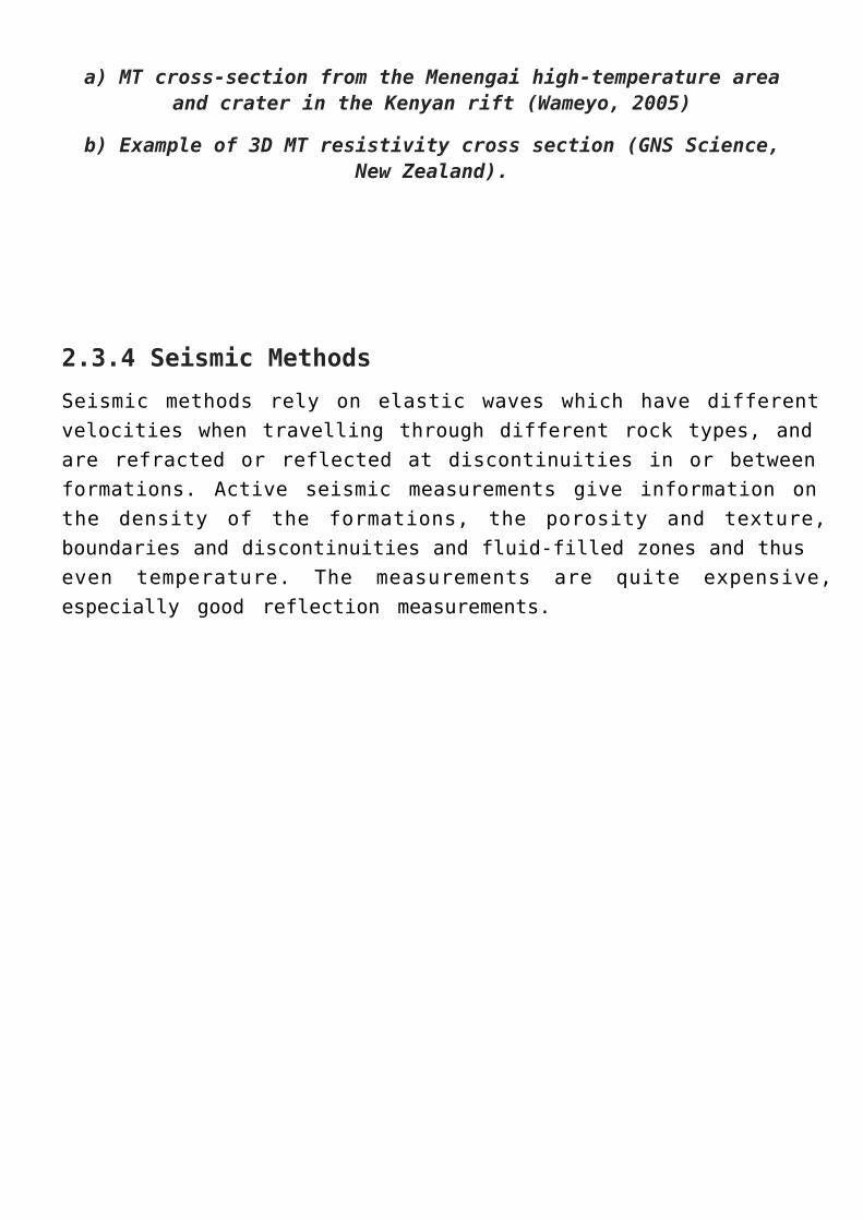
Magnetotellurics (MT) where current is induced by thetime variations in earth’s magnetic field. The measuredsignal is the electromagnetic field at the surface.
Fig 10
a) MT cross-section from the Menengai high-temperature areaand crater in the Kenyan rift (Wameyo, 2005)
b) Example of 3D MT resistivity cross section (GNS Science,New Zealand).
2.3.4 Seismic Methods Seismic methods rely on elastic waves which have differentvelocities when travelling through different rock types, andare refracted or reflected at discontinuities in or betweenformations. Active seismic measurements give information onthe density of the formations, the porosity and texture,boundaries and discontinuities and fluid-filled zones and thuseven temperature. The measurements are quite expensive,especially good reflection measurements.
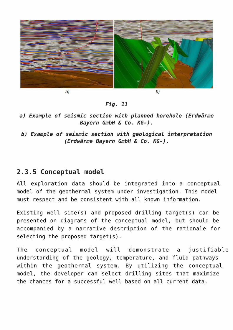
Fig. 11
a) Example of seismic section with planned borehole (ErdwärmeBayern GmbH & Co. KG-).
b) Example of seismic section with geological interpretation(Erdwärme Bayern GmbH & Co. KG-).
2.3.5 Conceptual modelAll exploration data should be integrated into a conceptualmodel of the geothermal system under investigation. This modelmust respect and be consistent with all known information.
Existing well site(s) and proposed drilling target(s) can bepresented on diagrams of the conceptual model, but should beaccompanied by a narrative description of the rationale forselecting the proposed target(s).
The conceptual model will demonstrate a justifiableunderstanding of the geology, temperature, and fluid pathwayswithin the geothermal system. By utilizing the conceptualmodel, the developer can select drilling sites that maximizethe chances for a successful well based on all current data.
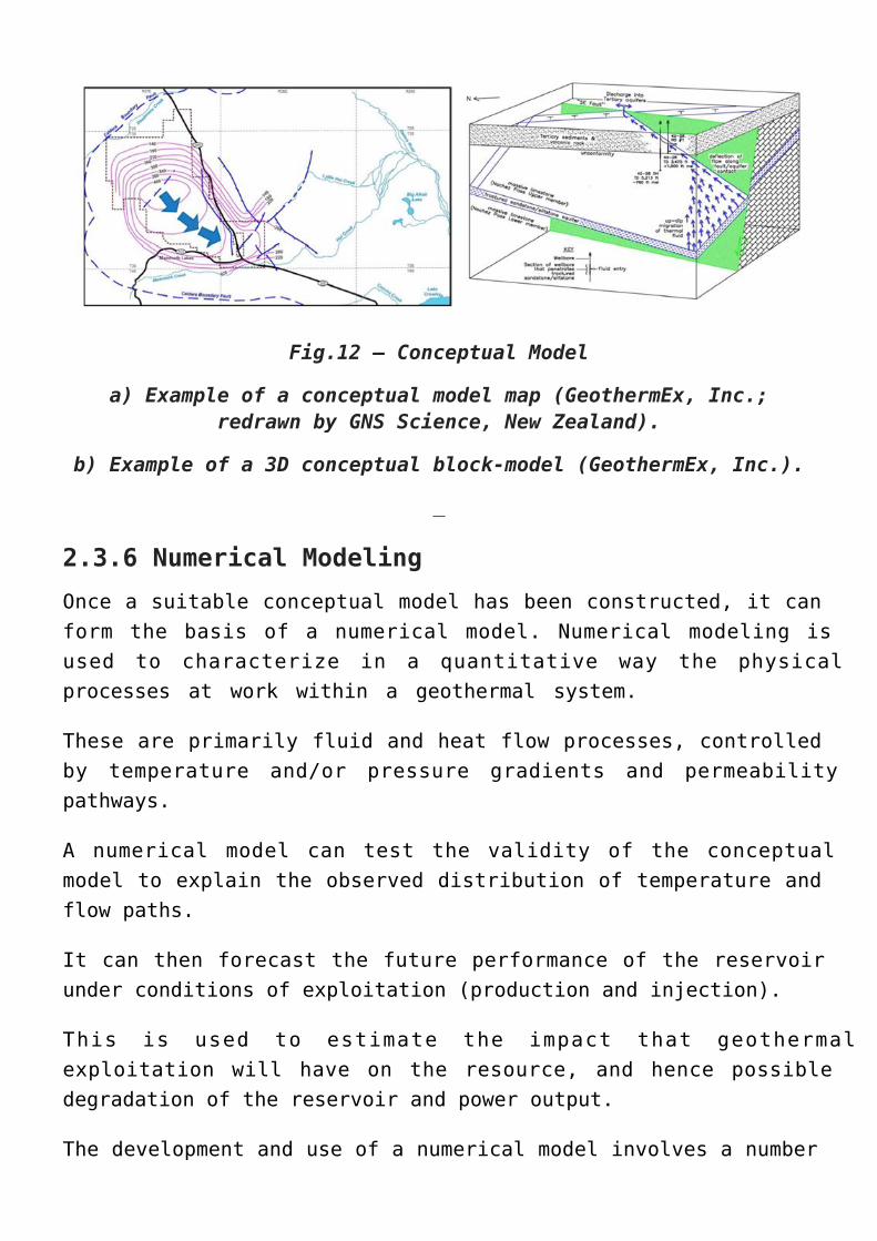
Fig.12 – Conceptual Model
a) Example of a conceptual model map (GeothermEx, Inc.;redrawn by GNS Science, New Zealand).
b) Example of a 3D conceptual block-model (GeothermEx, Inc.).
2.3.6 Numerical ModelingOnce a suitable conceptual model has been constructed, it canform the basis of a numerical model. Numerical modeling isused to characterize in a quantitative way the physicalprocesses at work within a geothermal system.
These are primarily fluid and heat flow processes, controlledby temperature and/or pressure gradients and permeabilitypathways.
A numerical model can test the validity of the conceptualmodel to explain the observed distribution of temperature andflow paths.
It can then forecast the future performance of the reservoirunder conditions of exploitation (production and injection).
This is used to estimate the impact that geothermalexploitation will have on the resource, and hence possibledegradation of the reservoir and power output.
The development and use of a numerical model involves a number
of stages, from initial state modeling to history matching andthen forecasts under a number of selected scenarios to predictthe future behavior of the reservoir under various levels ofproduction.
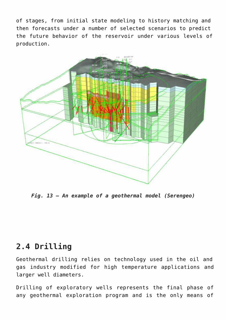
Fig. 13 – An example of a geothermal model (Serengeo)
2.4 DrillingGeothermal drilling relies on technology used in the oil andgas industry modified for high temperature applications andlarger well diameters.
Drilling of exploratory wells represents the final phase ofany geothermal exploration program and is the only means of
determining the real characteristics of the geothermalreservoir and thus of assessing its potential (Combs andMuffler, 1973).
Drilling the first wells in any project represents the periodof highest risk and typically, at least two but more oftenthree, deep wells are drilled to demonstrate the feasibilityof commercial production and injection. More wells may berequired, depending on the size of the project to be developedand the success in finding a viable geothermal resource withthe first series of wells.
Drilling, logging and testing significantly improve theunderstanding of the resource, enabling:
refinement of the estimate of the heat resource1.determination of the average well productivity (thus2.laying out the scope of future drilling)selection of the well sites, targets, well path and3.design for the remaining production and injection wellsdevelopment of a preliminary design for the power plant4.and gathering system
Upon completion of the test drilling phase, the project movestowards full feasibility.
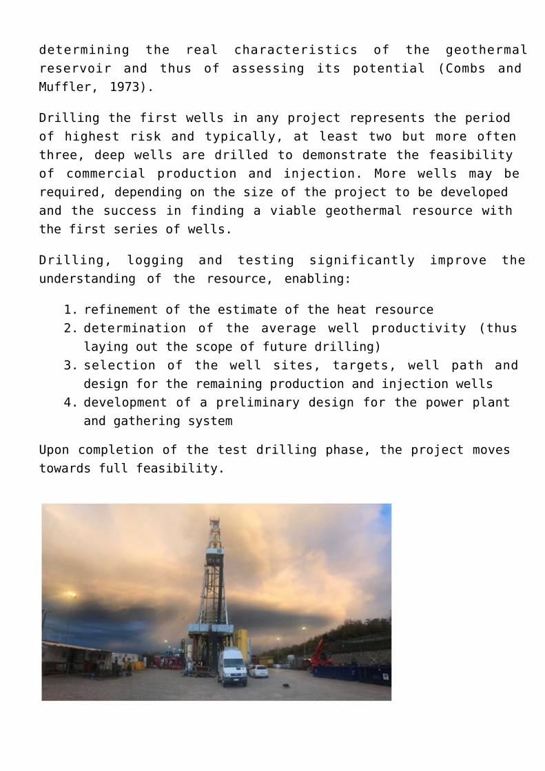
Fig. 14 – Geothermal well in Italy Venelle 2 – ENEL GreenPower
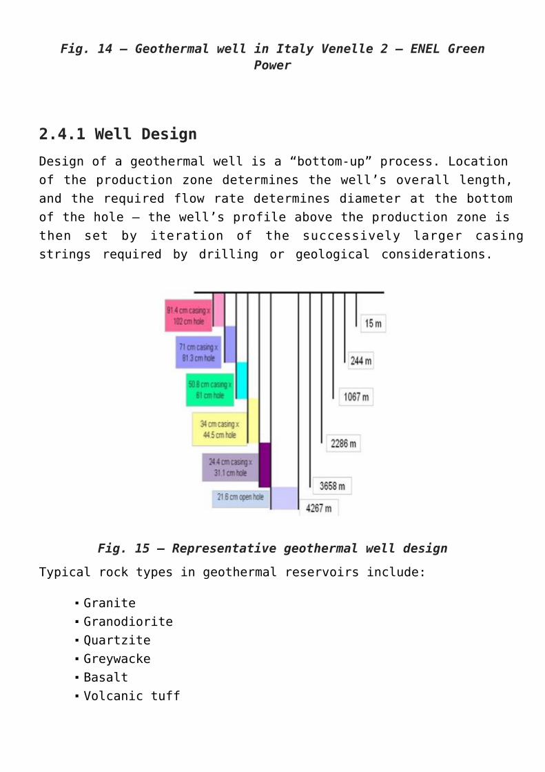
2.4.1 Well DesignDesign of a geothermal well is a “bottom-up” process. Locationof the production zone determines the well’s overall length,and the required flow rate determines diameter at the bottomof the hole – the well’s profile above the production zone isthen set by iteration of the successively larger casingstrings required by drilling or geological considerations.
Fig. 15 – Representative geothermal well design
Typical rock types in geothermal reservoirs include:
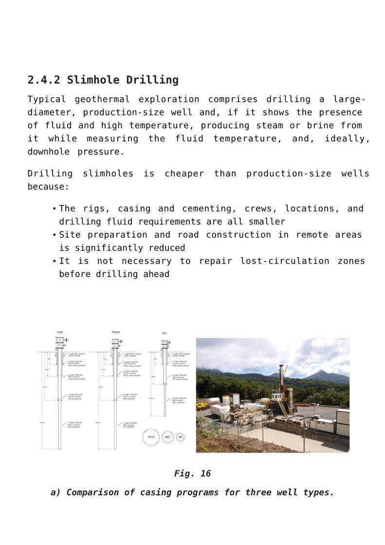
2.4.2 Slimhole Drilling Typical geothermal exploration comprises drilling a large-diameter, production-size well and, if it shows the presenceof fluid and high temperature, producing steam or brine fromit while measuring the fluid temperature, and, ideally,downhole pressure.
Drilling slimholes is cheaper than production-size wellsbecause:
The rigs, casing and cementing, crews, locations, anddrilling fluid requirements are all smallerSite preparation and road construction in remote areasis significantly reducedIt is not necessary to repair lost-circulation zonesbefore drilling ahead
Fig. 16
a) Comparison of casing programs for three well types.
b) Rig drilling a slim hole
2.5 Geothermal Drilling OperationsGeothermal drilling operations make use of several componentsand practices, some of this technology is shown and describedbelow:
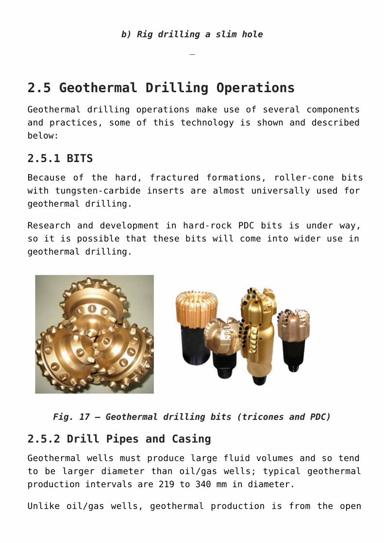
2.5.1 BITSBecause of the hard, fractured formations, roller-cone bitswith tungsten-carbide inserts are almost universally used forgeothermal drilling.
Research and development in hard-rock PDC bits is under way,so it is possible that these bits will come into wider use ingeothermal drilling.
Fig. 17 – Geothermal drilling bits (tricones and PDC)
2.5.2 Drill Pipes and CasingGeothermal wells must produce large fluid volumes and so tendto be larger diameter than oil/gas wells; typical geothermalproduction intervals are 219 to 340 mm in diameter.
Unlike oil/gas wells, geothermal production is from the open
hole or through a slotted liner, not through tubing.
Drillpipe suffers both erosion and corrosion. Both of theseproblems are aggravated by high temperature. Erosion is commonwhen air drilling, which is often done to avoid damaging theproduction interval with mud invasion, but properly hard-banding the tool joints will mitigate erosion. Casingproblems, other than cementing, usually deal with corrosionand scaling.
Many high-temperature drilling problems with downhole toolsand drilling fluids could be avoided or mitigated by usinginsulated drill pipe (IDP), which delivers cooler fluid to thebottom of the hole.
2.5.3. Drilling FluidsMost geothermal drilling fluids are a fairly simplewater/bentonite mixture with possible polymer additives. Largehole volumes and frequent lost circulation have a significantimpact on drilling cost.
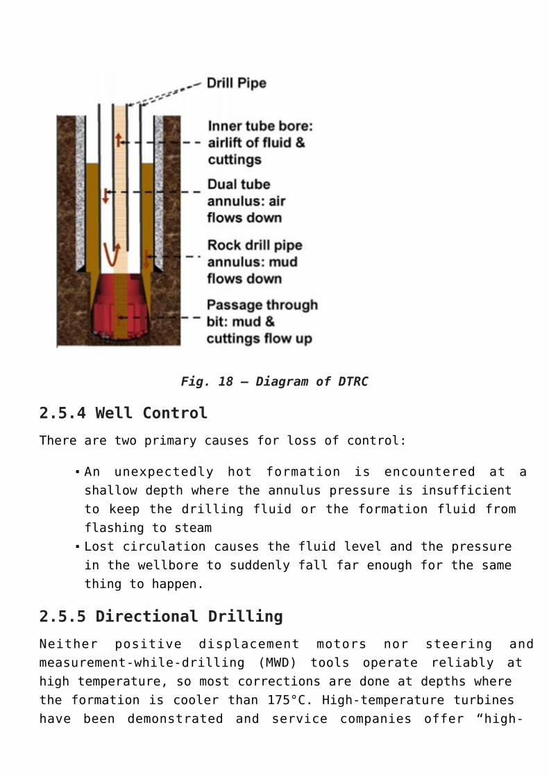
A technology that is useful with lost circulation is Dual-TubeReverse Circulation (DTRC). This method uses a drillstring oftwo concentric tubes, with the drilling fluid passing downannulus between the inner and outer tubes, circulating outthrough the bit, and carrying the cuttings back up through thecenter tube. This means that it is only necessary to maintainfluid around the bit and bottom-hole assembly, so drillingwith complete lost circulation is possible
Fig. 18 – Diagram of DTRC
2.5.4 Well ControlThere are two primary causes for loss of control:
An unexpectedly hot formation is encountered at ashallow depth where the annulus pressure is insufficientto keep the drilling fluid or the formation fluid fromflashing to steamLost circulation causes the fluid level and the pressurein the wellbore to suddenly fall far enough for the samething to happen.
2.5.5 Directional DrillingNeither positive displacement motors nor steering andmeasurement-while-drilling (MWD) tools operate reliably athigh temperature, so most corrections are done at depths wherethe formation is cooler than 175°C. High-temperature turbineshave been demonstrated and service companies offer “high-
temperature” positive displacement motors (PDM), but neitheris extensively used in geothermal drilling.
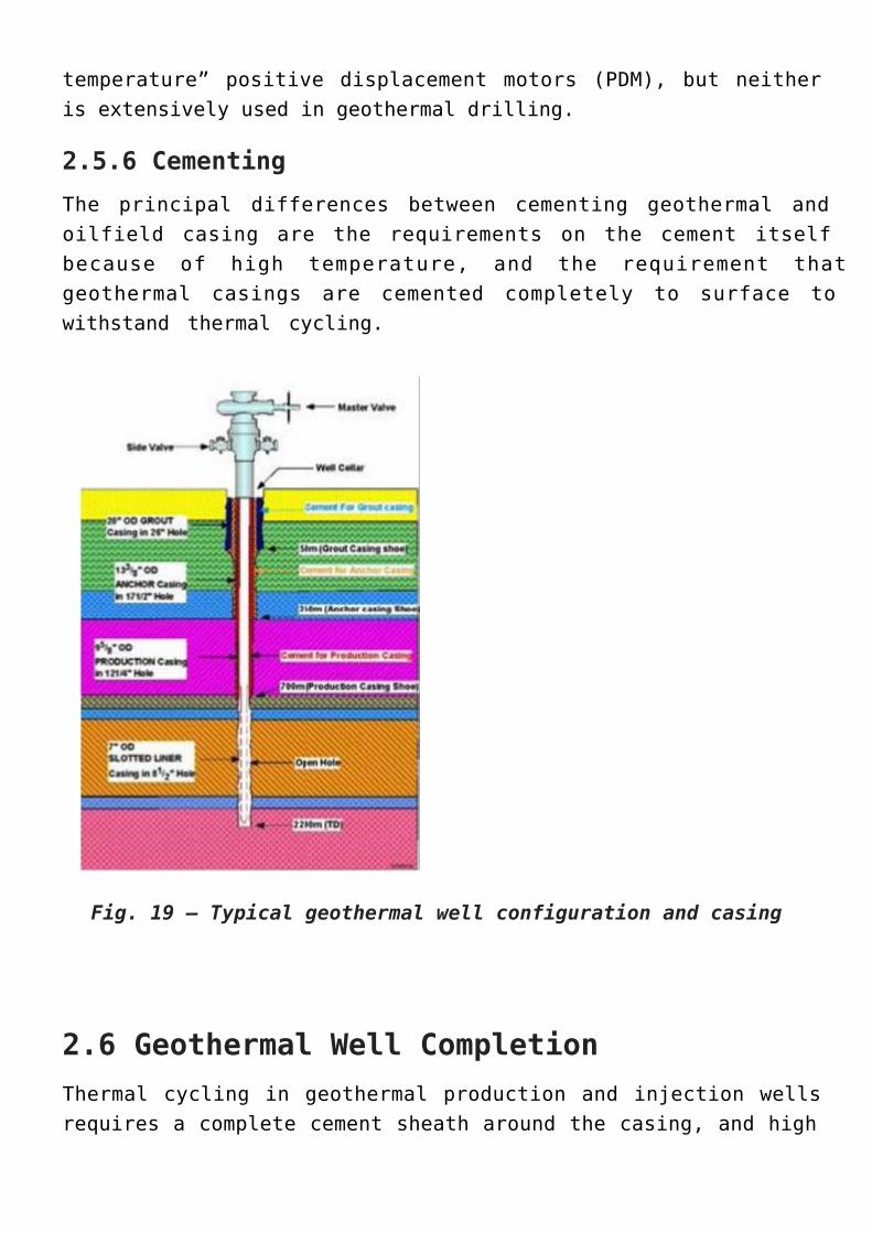
2.5.6 CementingThe principal differences between cementing geothermal andoilfield casing are the requirements on the cement itselfbecause of high temperature, and the requirement thatgeothermal casings are cemented completely to surface towithstand thermal cycling.
Fig. 19 – Typical geothermal well configuration and casing
2.6 Geothermal Well CompletionThermal cycling in geothermal production and injection wellsrequires a complete cement sheath around the casing, and high
production flow rates (often > 100,000 kg/hr) mean that casingis usually larger in diameter than for many oil/gas wells.Whether the production interval is stable enough to beopenhole or must be completed with a slotted liner.
2.7 Geothermal Energy Production PlantsOnce a reservoir is found and characterized, surfacetechnology, the power plant and related infrastructure, mustbe designed and equipment selected to optimize the use andsustainability of the resource. The goal is to construct anenergy efficient, low cost, minimal-impact plan.
Many uses and technologies have been developed to takeadvantage of geothermal energy:
Geothermal energy for electricity production1.Geothermal energy direct uses2.Geothermal heat pumps3.
2.7.1 Geothermal Energy for Electricity ProductionMost conventional power plants use steam to generateelectricity. Whereas fossil-fuel plants burn coal, oil or gasto boil water, many existing geothermal power plants use steamproduced by “flashing” (i.e. reducing the pressure of) thegeothermal fluid produced from the reservoir. Geothermal powerplants today can use water in the vapour phase, a combinationof vapour and liquid phases, or liquid phase only. The choiceof plant depends on the depth of the reservoir, and thetemperature, pressure and nature of the entire geothermalresource.
The three main types of plant are
flash steam1.dry steam2.
binary plants3.
All forms of current accepted geothermal development use re-injection as a means of sustainable resource exploitation.
A.FLASH STEAM PLANTS
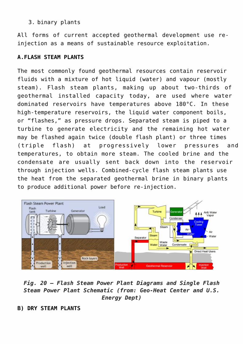
The most commonly found geothermal resources contain reservoirfluids with a mixture of hot liquid (water) and vapour (mostlysteam). Flash steam plants, making up about two-thirds ofgeothermal installed capacity today, are used where waterdominated reservoirs have temperatures above 180°C. In thesehigh-temperature reservoirs, the liquid water component boils,or “flashes,” as pressure drops. Separated steam is piped to aturbine to generate electricity and the remaining hot watermay be flashed again twice (double flash plant) or three times(triple flash) at progressively lower pressures andtemperatures, to obtain more steam. The cooled brine and thecondensate are usually sent back down into the reservoirthrough injection wells. Combined-cycle flash steam plants usethe heat from the separated geothermal brine in binary plantsto produce additional power before re-injection.
Fig. 20 – Flash Steam Power Plant Diagrams and Single FlashSteam Power Plant Schematic (from: Geo-Heat Center and U.S.
Energy Dept)
B) DRY STEAM PLANTS
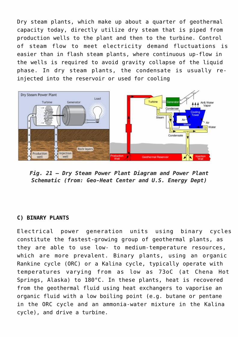
Dry steam plants, which make up about a quarter of geothermalcapacity today, directly utilize dry steam that is piped fromproduction wells to the plant and then to the turbine. Controlof steam flow to meet electricity demand fluctuations iseasier than in flash steam plants, where continuous up-flow inthe wells is required to avoid gravity collapse of the liquidphase. In dry steam plants, the condensate is usually re-injected into the reservoir or used for cooling
Fig. 21 – Dry Steam Power Plant Diagram and Power PlantSchematic (from: Geo-Heat Center and U.S. Energy Dept)
C) BINARY PLANTS
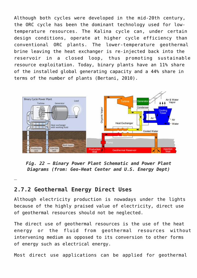
Electrical power generation units using binary cyclesconstitute the fastest-growing group of geothermal plants, asthey are able to use low- to medium-temperature resources,which are more prevalent. Binary plants, using an organicRankine cycle (ORC) or a Kalina cycle, typically operate withtemperatures varying from as low as 73oC (at Chena HotSprings, Alaska) to 180°C. In these plants, heat is recoveredfrom the geothermal fluid using heat exchangers to vaporise anorganic fluid with a low boiling point (e.g. butane or pentanein the ORC cycle and an ammonia-water mixture in the Kalinacycle), and drive a turbine.
Although both cycles were developed in the mid-20th century,the ORC cycle has been the dominant technology used for low-temperature resources. The Kalina cycle can, under certaindesign conditions, operate at higher cycle efficiency thanconventional ORC plants. The lower-temperature geothermalbrine leaving the heat exchanger is re-injected back into thereservoir in a closed loop, thus promoting sustainableresource exploitation. Today, binary plants have an 11% shareof the installed global generating capacity and a 44% share interms of the number of plants (Bertani, 2010).
Fig. 22 – Binary Power Plant Schematic and Power PlantDiagrams (from: Geo-Heat Center and U.S. Energy Dept)
2.7.2 Geothermal Energy Direct UsesAlthough electricity production is nowadays under the lightsbecause of the highly praised value of electricity, direct useof geothermal resources should not be neglected.
The direct use of geothermal resources is the use of the heatenergy or the fluid from geothermal resources withoutintervening medium as opposed to its conversion to other formsof energy such as electrical energy.
Most direct use applications can be applied for geothermal
fluids in the low to moderate temperature range 20 – 120°C.Low to medium temperature geothermal resources have been usedfor ages especially in a first time for bathing and later onfor space heating and farming applications.
Low and medium temperature geothermal fields can be found inmany places around the world. Such fields can hardly beutilized for power generation in steam turbines nor binaryplants, mainly due to economic reasons. These fields mighthowever fit perfectly for direct use applications.
Geothermal heat is used directly, without involving a powerplant or a heat pump, for a variety of applications such asspace heating and cooling, food preparation, hot springbathing and spas (balneology), agriculture, aquaculture,greenhouses, and industrial processes. Uses for heating andbathing are traced back to ancient Roman times.
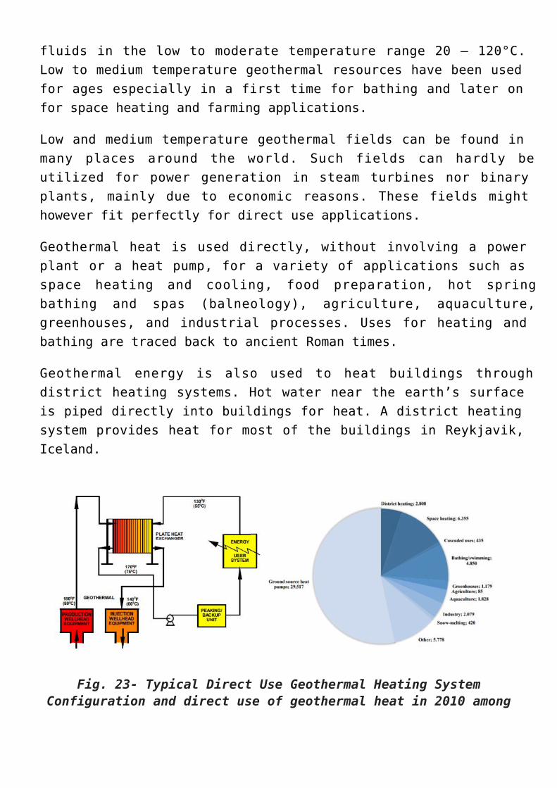
Geothermal energy is also used to heat buildings throughdistrict heating systems. Hot water near the earth’s surfaceis piped directly into buildings for heat. A district heatingsystem provides heat for most of the buildings in Reykjavik,Iceland.
Fig. 23- Typical Direct Use Geothermal Heating SystemConfiguration and direct use of geothermal heat in 2010 among
the IEA-GIA countries (GWh/a)
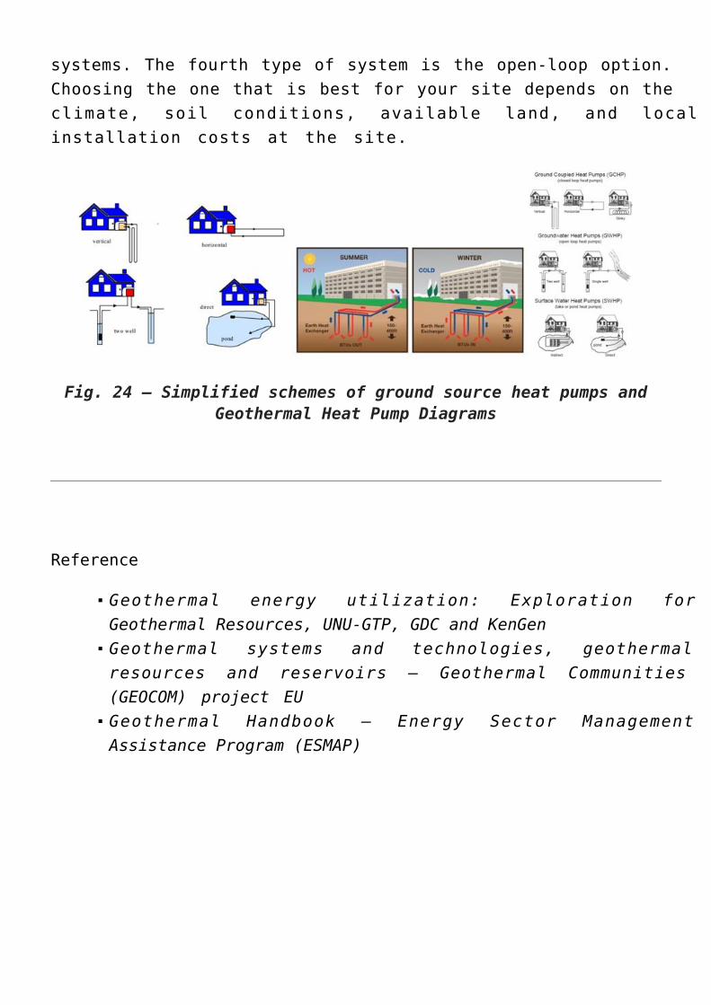
2.7.3. Geothermal Heat Pumps (GHPs)Geothermal heat pumps take advantage of the Earth’s relativelyconstant temperature at depths of about 10 ft to 300 ft. GHPscan be used almost everywhere in the world, as they do notshare the requirements of fractured rock and water as areneeded for a conventional geothermal reservoir.
Geothermal heat pump systems consist of basically three parts:
the ground heat exchangerthe heat pump unitthe air delivery system (ductwork)
The heat exchanger is basically a system of pipes called aloop, which is buried in the shallow ground near the building.A fluid (usually water or a mixture of water and antifreeze)circulates through the pipes to absorb or relinquish heatwithin the ground.
In the winter, the heat pump removes heat from the heatexchanger and pumps it into the indoor air delivery system. Inthe summer, the process is reversed, and the heat pump movesheat from the indoor air into the heat exchanger.
The heat removed from the indoor air during the summer canalso be used to heat water, providing a free source of hotwater.
GHPs reduce electricity use 30–60% compared with traditionalheating and cooling systems, because the electricity whichpowers them is used only to collect, concentrate, and deliverheat, not to produce it.
Geothermal heat pumps come in four types of loop systems thatloop the heat to or from the ground and your house. Three ofthese – horizontal, vertical, and pond/lake – are closed-loop
systems. The fourth type of system is the open-loop option.Choosing the one that is best for your site depends on theclimate, soil conditions, available land, and localinstallation costs at the site.
Geothermal energy utilization: Exploration forGeothermal Resources, UNU-GTP, GDC and KenGenGeothermal systems and technologies, geothermalresources and reservoirs – Geothermal Communities(GEOCOM) project EUGeothermal Handbook – Energy Sector ManagementAssistance Program (ESMAP)