36
Hoval UltraGas ® AM Condensing Boilers 15-90 kW and 125-1440 kW
Hoval UltraGas® AMCondensing Boilers15-90 kW and 125-1440 kW
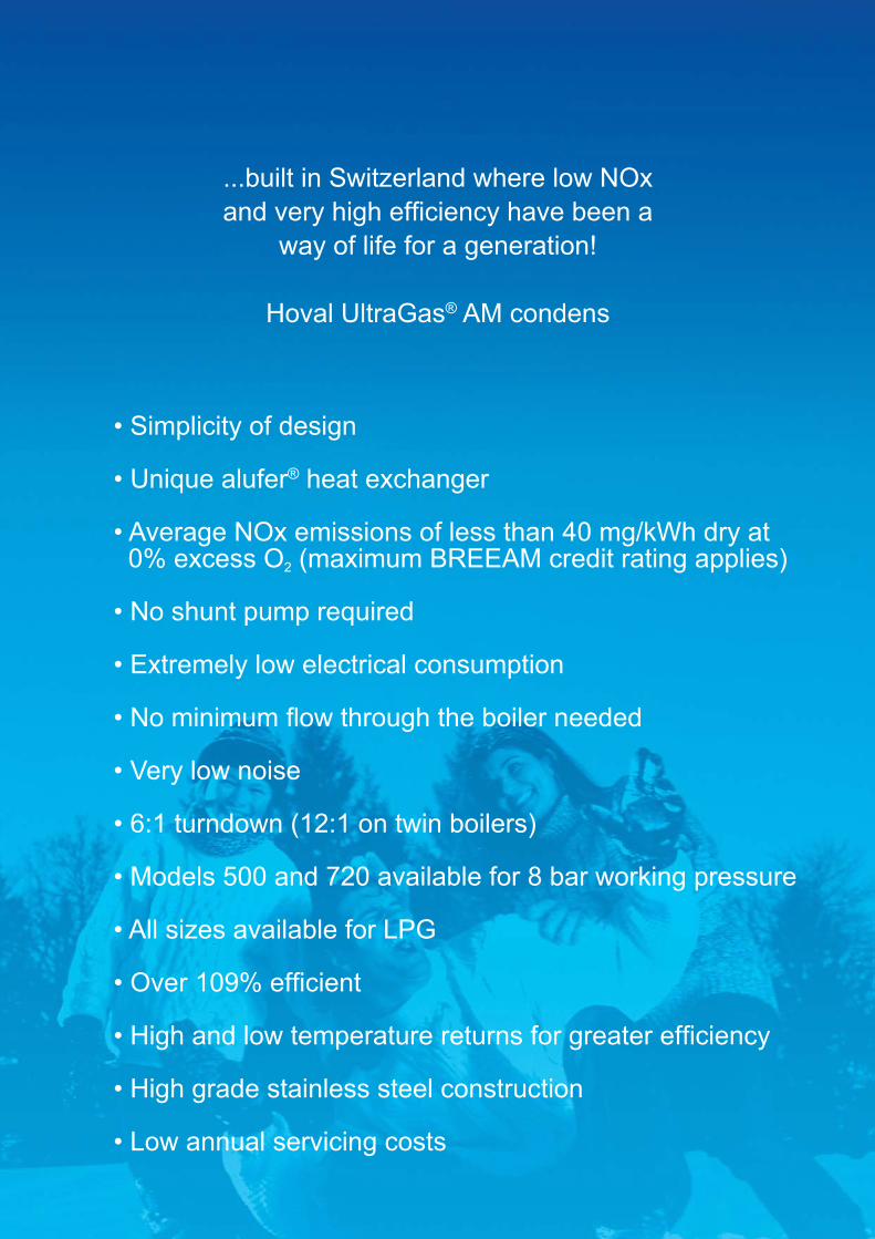
...built in Switzerland where low NOxand very high effi ciency have been a
way of life for a generation!
Hoval UltraGas® AM condens
• Simplicity of design
• Unique alufer® heat exchanger
• Average NOx emissions of less than 40 mg/kWh dry at 0% excess O2 (maximum BREEAM credit rating applies)
• No shunt pump required
• Extremely low electrical consumption
• No minimum fl ow through the boiler needed
• Very low noise
• 6:1 turndown (12:1 on twin boilers)
• Models 500 and 720 available for 8 bar working pressure
• All sizes available for LPG
• Over 109% effi cient
• High and low temperature returns for greater effi ciency
• High grade stainless steel construction
• Low annual servicing costs
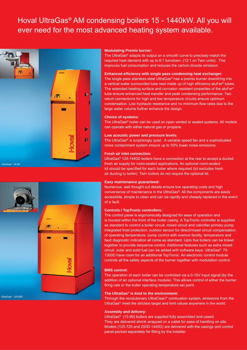
Modulating Premix burner:The UltraGas® adapts its output on a smooth curve to precisely match the required heat demand with up to 6:1 turndown. (12:1 on Twin units). This improves fuel consumption and reduces the carbon dioxide emission.
Enhanced effi ciency with single pass condensing heat exchanger:The single pass stainless steel UltraGas® has a premix burner downfi ring into a vertical water surrounded tube nest made up of high effi ciency aluFer® tubes. The extended heating surface and corrosion resistant properties of the aluFer® tube ensure enhanced heat transfer and peak condensing performance. Two return connections for high and low temperature circuits ensure optimum condensation. Low hydraulic resistance and no minimum fl ow rates due to the large water volume further enhance the design.
Choice of systems:The UltraGas® boiler can be used on open vented or sealed systems. All models can operate with either natural gas or propane.
Low acoustic power and pressure levels:The UltraGas® is surprisingly quiet. A variable speed fan and a sophisticated noise containment system ensure up to 50% lower noise emissions.
Fresh air inlet connection:UltraGas® 125-1440D boilers have a connection at the rear to accept a ductedfresh air supply for room-sealed applications. An optional room-sealedkit should be specifi ed for each boiler where required (kit excludes freshair ducting to boiler). Twin boilers do not require the optional kit.
Easy maintenance guaranteed: Numerous, well thought out details ensure low operating costs and high convenience of maintenance in the UltraGas®. All the components are easily accessible, simple to clean and can be rapidly and cheaply replaced in the event of a fault.
Controls / TopTronic controllers:The control panel is ergonomically designed for ease of operation andis housed within the front of the boiler casing. A TopTronic controller is supplied as standard to control a boiler circuit, mixed circuit and calorifi er primary pump. Integrated frost protection, outdoor sensor for direct/mixed circuit compensation of operating temperature, pump control with overrun facility, temperature and fault diagnostic indication all come as standard. Upto fi ve boilers can be linked together to provide sequence control. Additional features such as extra mixed circuit, solar and solid fuel can be added with software keys. UltraGas® 70-1300D have room for an additional TopTronic. An electronic control module controls all the safety aspects of the burner together with modulation control.
BMS control:The operation of each boiler can be controlled via a 0-10V input signal (by the addition of an optional interface module). This allows control of either the burner fi ring rate or the boiler operating temperature set point.
The UltraGas® is kind to the environment: Through the revolutionary UltraClean® combustion system, emissions from the UltraGas® meet the strictest target and limit values anywhere in the world.
Assembly and delivery:UltraGas® (15-90) boilers are supplied fully assembled and cased.They are delivered shrink wrapped on a pallet for ease of handling on site. Models (125-720 and 250D-1440D) are delivered with the casings and control panel packed separately for fi tting by the installer.
Hoval UltraGas® AM condensing boilers 15 - 1440kW. All you will ever need for the most advanced heating system available.
UltraGas® 35-90
UltraGas® 125-650
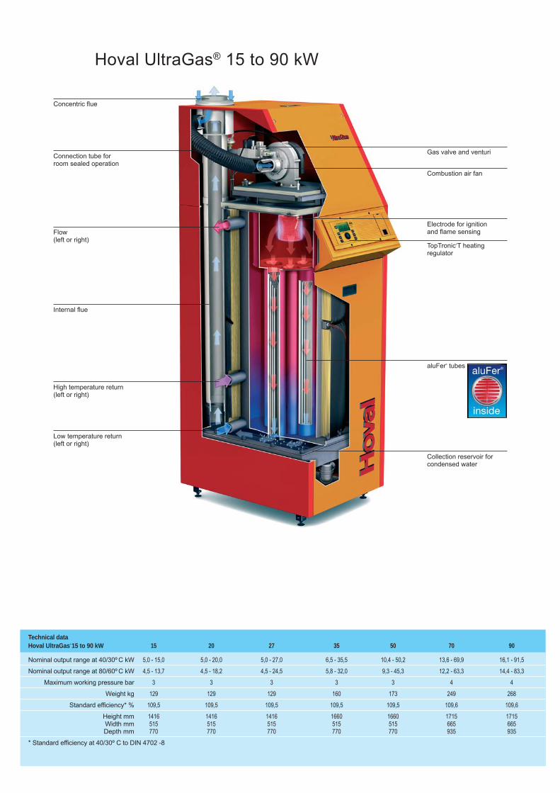
Hoval UltraGas® 15 to 90 kW
Concentric flue
Gas valve and venturi
Combustion air fan
Electrode for ignitionand flame sensing
TopTronic®T heatingregulator
aluFer® tubes
Collection reservoir forcondensed water
Connection tube forroom sealed operation
Flow (left or right)
Internal flue
High temperature return (left or right)
Low temperature return(left or right)
Technical dataHoval UltraGas®
15 to 90 kW 15 20 27 35 50 70 90
Nominal output range at 40/30º C kW 5,0 - 15,0 5,0 - 20,0 5,0 - 27,0 6,5 - 35,5 10,4 - 50,2 13,6 - 69,9 16,1 - 91,5
Nominal output range at 80/60º C kW 4,5 - 13,7 4,5 - 18,2 4,5 - 24,5 5,8 - 32,0 9,3 - 45,3 12,2 - 63,3 14,4 - 83,3
Maximum working pressure bar 3 3 3 3 3 4 4
Weight kg 129 129 129 160 173 249 268
Standard efficiency* % 109,5 109,5 109,5 109,5 109,5 109,6 109,6
Height mm 1416 1416 1416 1660 1660 1715 1715 Width mm 515 515 515 515 515 665 665 Depth mm 770 770 770 770 770 935 935
* Standard efficiency at 40/30º C to DIN 4702 -8
Technical dataHoval UltraGas®
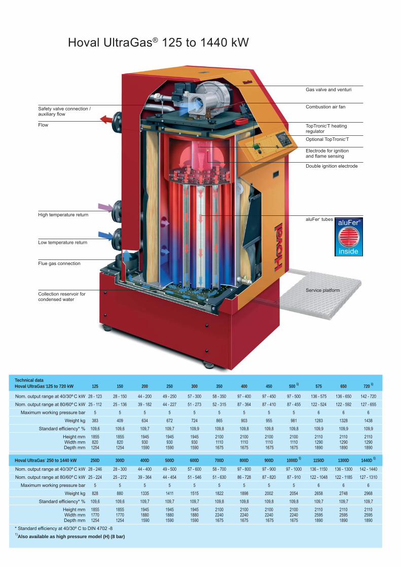
125 to 720 kW 125 150 200 250 300 350 400 450 500 1) 575 650 720 1)
Nom. output range at 40/30º C kW 28 - 123 28 - 150 44 - 200 49 - 250 57 - 300 58 - 350 97 - 400 97 - 450 97 - 500 136 - 575 136 - 650 142 - 720
Nom. output range at 80/60º C kW 25 - 112 25 - 136 39 - 182 44 - 227 51 - 273 52 - 315 87 - 364 87 - 410 87 - 455 122 - 524 122 - 592 127 - 655
Maximum working pressure bar 5 5 5 5 5 5 5 5 5 6 6 6
Weight kg 383 409 634 672 724 865 903 955 981 1283 1328 1438
Standard efficiency* % 109,6 109,6 109,7 109,7 109,9 109,8 109,8 109,8 109,8 109,9 109,9 109,9
Height mm 1855 1855 1945 1945 1945 2100 2100 2100 2100 2110 2110 2110 Width mm 820 820 930 930 930 1110 1110 1110 1110 1290 1290 1290 Depth mm 1254 1254 1590 1590 1590 1675 1675 1675 1675 1890 1890 1890
Hoval UltraGas® 250 to 1440 kW 250D 300D 400D 500D 600D 700D 800D 900D 1000D 1) 1150D 1300D 1440D 1)
Nom. output range at 40/30º C kW 28 - 246 28 - 300 44 - 400 49 - 500 57 - 600 58 - 700 97 - 800 97 - 900 97 - 1000 136 - 1150 136 - 1300 142 - 1440
Nom. output range at 80/60º C kW 25 - 224 25 - 272 39 - 364 44 - 454 51 - 546 51 - 630 86 - 728 87 - 820 87 - 910 122 - 1048 122 - 1185 127 - 1310
Maximum working pressure bar 5 5 5 5 5 5 5 5 5 6 6 6
Weight kg 828 880 1335 1411 1515 1822 1898 2002 2054 2658 2748 2968
Standard efficiency* % 109,6 109,6 109,7 109,7 109,7 109,8 109,8 109,8 109,8 109,7 109,7 109,7
Height mm 1855 1855 1945 1945 1945 2100 2100 2100 2100 2110 2110 2110 Width mm 1770 1770 1880 1880 1880 2240 2240 2240 2240 2595 2595 2595 Depth mm 1254 1254 1590 1590 1590 1675 1675 1675 1675 1890 1890 1890
* Standard efficiency at 40/30º C to DIN 4702 -81)Also available as high pressure model (H) (8 bar)
Hoval UltraGas® 125 to 1440 kW
Safety valve connection /auxiliary flow
Flow
High temperature return
Low temperature return
Flue gas connection
Collection reservoir forcondensed water
Gas valve and venturi
Combustion air fan
Electrode for ignitionand flame sensing
Service platform
aluFer® tubes
Double ignition electrode
TopTronic®T heatingregulator
Optional TopTronic®T
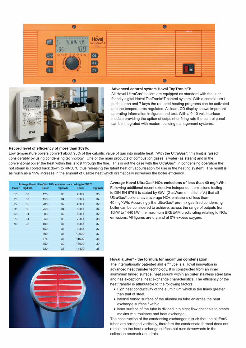
Record level of effi ciency of more than 109%: Low temperature boilers convert about 93% of the calorifi c value of gas into usable heat. With the UltraGas®, this limit is raised considerably by using condensing technology. One of the main products of combustion gases is water (as steam) and in the conventional boiler the heat within this is lost through the fl ue. This is not the case with the UltraGas®; in condensing operation the hot steam is cooled back down to 40-50°C thus releasing the latent heat of vapourisation for use in the heating system. The result is as much as a 15% increase in the amount of usable heat which dramatically increases the boiler effi ciency.
Hoval aluFer® - the formula for maximum condensation:The internationally patented aluFer® tube is a Hoval innovation in advanced heat transfer technology. It is constructed from an inner aluminium fi nned surface, heat shrunk within an outer stainless steel tube and has exceptional heat exchange characteristics. The effi ciency of the heat transfer is attributable to the following factors: ● High heat conductivity of the aluminium which is ten times greater than that of steel. ● Internal fi nned surface of the aluminium tube enlarges the heat
exchange surface fi vefold. ● Inner surface of the tube is divided into eight fl ow channels to create
maximum turbulence and heat exchange.The construction of the condensing exchanger is such that the aluFer® tubes are arranged vertically, therefore the condensate formed does not remain on the heat exchange surface but runs downwards to the collection reservoir and drain.
Advanced control system Hoval TopTronic®T:All Hoval UltraGas® boilers are equipped as standard with the user friendly digital Hoval TopTronic®T control system. With a central turn / push button and 7 keys the required heating programs can be activated and the temperatures regulated. A clear LCD display shows important operating information in fi gures and text. With a 0-10 volt interface module providing the option of setpoint or fi ring rate the control panel can be integrated with modern building management systems.
Average Hoval UltraGas® NOx emissions according to EN676 Boiler mg/kWh Boiler mg/kWh Boiler mg/kWh
15 37 125 35 250D 35
20 37 150 34 300D 34
27 35 200 32 400D 32
35 30 250 34 500D 34
50 31 300 32 600D 32
70 31 350 38 700D 38
90 38 400 37 800D 37
450 37 900D 37
500 37 1000D 37
575 36 1150D 36
650 39 1300D 39
720 35 1440D 35
Average Hoval UltraGas® NOx emissions of less than 40 mg/kWh:Following additional recent extensive independent emissions testing to DIN EN 676 it is stated by GWI (GasWarme Institut e.V.) that all UltraGas® boilers have average NOx emissions of less than 40 mg/kWh. Accordingly the UltraGas® pre-mix gas fi red condensing boiler can be considered to achieve, across the range of outputs from 15kW to 1440 kW, the maximum BREEAM credit rating relating to NOx emissions. All fi gures are dry and at 0% excess oxygen.
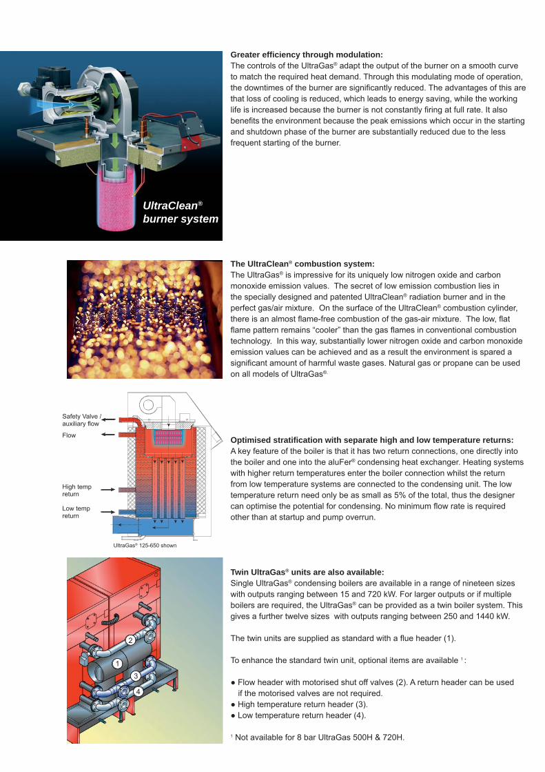
Greater effi ciency through modulation:The controls of the UltraGas® adapt the output of the burner on a smooth curve to match the required heat demand. Through this modulating mode of operation, the downtimes of the burner are signifi cantly reduced. The advantages of this are that loss of cooling is reduced, which leads to energy saving, while the working life is increased because the burner is not constantly fi ring at full rate. It also benefi ts the environment because the peak emissions which occur in the starting and shutdown phase of the burner are substantially reduced due to the less frequent starting of the burner.
The UltraClean® combustion system: The UltraGas® is impressive for its uniquely low nitrogen oxide and carbon monoxide emission values. The secret of low emission combustion lies in the specially designed and patented UltraClean® radiation burner and in the perfect gas/air mixture. On the surface of the UltraClean® combustion cylinder, there is an almost fl ame-free combustion of the gas-air mixture. The low, fl at fl ame pattern remains “cooler” than the gas fl ames in conventional combustion technology. In this way, substantially lower nitrogen oxide and carbon monoxide emission values can be achieved and as a result the environment is spared a signifi cant amount of harmful waste gases. Natural gas or propane can be used on all models of UltraGas®.
Optimised stratifi cation with separate high and low temperature returns:A key feature of the boiler is that it has two return connections, one directly into the boiler and one into the aluFer® condensing heat exchanger. Heating systems with higher return temperatures enter the boiler connection whilst the return from low temperature systems are connected to the condensing unit. The low temperature return need only be as small as 5% of the total, thus the designer can optimise the potential for condensing. No minimum fl ow rate is required other than at startup and pump overrun.
Twin UltraGas® units are also available:Single UltraGas® condensing boilers are available in a range of nineteen sizes with outputs ranging between 15 and 720 kW. For larger outputs or if multiple boilers are required, the UltraGas® can be provided as a twin boiler system. This gives a further twelve sizes with outputs ranging between 250 and 1440 kW.
The twin units are supplied as standard with a fl ue header (1).
To enhance the standard twin unit, optional items are available 1 :
● Flow header with motorised shut off valves (2). A return header can be used if the motorised valves are not required.● High temperature return header (3).● Low temperature return header (4).
1 Not available for 8 bar UltraGas 500H & 720H.
UltraClean®
burner system
Flow
High tempreturn
Low tempreturn
4
2
3
1
Safety Valve /auxiliary fl ow
UltraGas® 125-650 shown
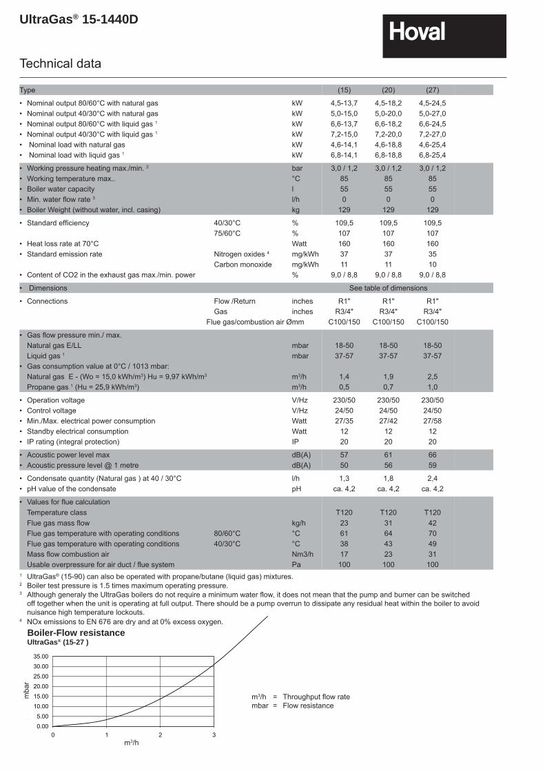
UltraGas® 15-1440D
Type (15) (20) (27)
• Nominal output 80/60°C with natural gas kW 4,5-13,7 4,5-18,2 4,5-24,5• Nominal output 40/30°C with natural gas kW 5,0-15,0 5,0-20,0 5,0-27,0• Nominal output 80/60°C with liquid gas 1 kW 6,6-13,7 6,6-18,2 6,6-24,5• Nominal output 40/30°C with liquid gas 1 kW 7,2-15,0 7,2-20,0 7,2-27,0• Nominal load with natural gas kW 4,6-14,1 4,6-18,8 4,6-25,4• Nominal load with liquid gas 1 kW 6,8-14,1 6,8-18,8 6,8-25,4
• Working pressure heating max./min. 2 bar 3,0 / 1,2 3,0 / 1,2 3,0 / 1,2• Working temperature max.. °C 85 85 85• Boiler water capacity l 55 55 55• Min. water fl ow rate 3 l/h 0 0 0• Boiler Weight (without water, incl. casing) kg 129 129 129
• Standard effi ciency 40/30°C % 109,5 109,5 109,575/60°C % 107 107 107
• Heat loss rate at 70°C Watt 160 160 160• Standard emission rate Nitrogen oxides 4 mg/kWh 37 37 35
Carbon monoxide mg/kWh 11 11 10• Content of CO2 in the exhaust gas max./min. power % 9,0 / 8,8 9,0 / 8,8 9,0 / 8,8
• Dimensions See table of dimensions
• Connections Flow /Return inches R1" R1" R1"Gas inches R3/4" R3/4" R3/4"
Flue gas/combustion air Ø mm C100/150 C100/150 C100/150
• Gas fl ow pressure min./ max.Natural gas E/LL mbar 18-50 18-50 18-50Liquid gas 1 mbar 37-57 37-57 37-57
• Gas consumption value at 0°C / 1013 mbar:Natural gas E - (Wo = 15,0 kWh/m3) Hu = 9,97 kWh/m3 m3/h 1,4 1,9 2,5Propane gas 1 (Hu = 25,9 kWh/m3) m3/h 0,5 0,7 1,0
• Operation voltage V/Hz 230/50 230/50 230/50• Control voltage V/Hz 24/50 24/50 24/50• Min./Max. electrical power consumption Watt 27/35 27/42 27/58• Standby electrical consumption Watt 12 12 12• IP rating (integral protection) IP 20 20 20
• Acoustic power level max dB(A) 57 61 66• Acoustic pressure level @ 1 metre dB(A) 50 56 59
• Condensate quantity (Natural gas ) at 40 / 30°C l/h 1,3 1,8 2,4• pH value of the condensate pH ca. 4,2 ca. 4,2 ca. 4,2
• Values for fl ue calculationTemperature class T120 T120 T120Flue gas mass fl ow kg/h 23 31 42Flue gas temperature with operating conditions 80/60°C °C 61 64 70Flue gas temperature with operating conditions 40/30°C °C 38 43 49Mass fl ow combustion air Nm3/h 17 23 31Usable overpressure for air duct / fl ue system Pa 100 100 100
1 UltraGas® (15-90) can also be operated with propane/butane (liquid gas) mixtures.2 Boiler test pressure is 1.5 times maximum operating pressure.3 Although generaly the UltraGas boilers do not require a minimum water flow, it does not mean that the pump and burner can be switched
off together when the unit is operating at full output. There should be a pump overrun to dissipate any residual heat within the boiler to avoid nuisance high temperature lockouts.
4 NOx emissions to EN 676 are dry and at 0% excess oxygen.
0.00
5.00
10.00
15.00
20.00
25.00
30.00
35.00
0 1 2 3Volumenstrom [m3/h]
Dru
ckve
rlust
[mba
r]
Boiler-Flow resistanceUltraGas® (15-27 )
m3/h = Throughput fl ow ratembar = Flow resistance
m3/h
mba
r
Technical data
UltraGas® 15-1440D
Technical data
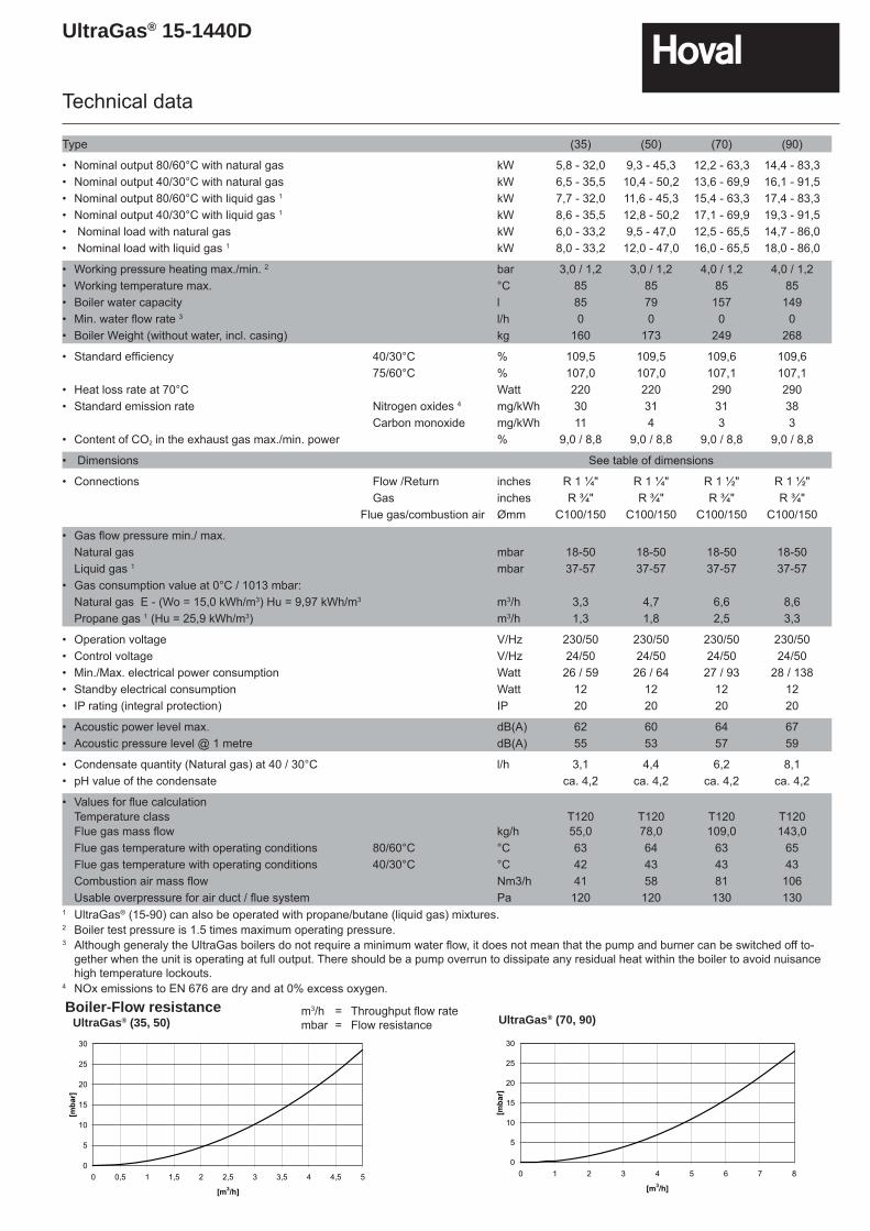
Type (35) (50) (70) (90)
• Nominal output 80/60°C with natural gas kW 5,8 - 32,0 9,3 - 45,3 12,2 - 63,3 14,4 - 83,3• Nominal output 40/30°C with natural gas kW 6,5 - 35,5 10,4 - 50,2 13,6 - 69,9 16,1 - 91,5• Nominal output 80/60°C with liquid gas 1 kW 7,7 - 32,0 11,6 - 45,3 15,4 - 63,3 17,4 - 83,3• Nominal output 40/30°C with liquid gas 1 kW 8,6 - 35,5 12,8 - 50,2 17,1 - 69,9 19,3 - 91,5• Nominal load with natural gas kW 6,0 - 33,2 9,5 - 47,0 12,5 - 65,5 14,7 - 86,0• Nominal load with liquid gas 1 kW 8,0 - 33,2 12,0 - 47,0 16,0 - 65,5 18,0 - 86,0
• Working pressure heating max./min. 2 bar 3,0 / 1,2 3,0 / 1,2 4,0 / 1,2 4,0 / 1,2• Working temperature max. °C 85 85 85 85• Boiler water capacity l 85 79 157 149• Min. water fl ow rate 3 l/h 0 0 0 0• Boiler Weight (without water, incl. casing) kg 160 173 249 268
• Standard effi ciency 40/30°C % 109,5 109,5 109,6 109,675/60°C % 107,0 107,0 107,1 107,1
• Heat loss rate at 70°C Watt 220 220 290 290• Standard emission rate Nitrogen oxides 4 mg/kWh 30 31 31 38
Carbon monoxide mg/kWh 11 4 3 3• Content of CO2 in the exhaust gas max./min. power % 9,0 / 8,8 9,0 / 8,8 9,0 / 8,8 9,0 / 8,8
• Dimensions See table of dimensions
• Connections Flow /Return inches R 1 ¼" R 1 ¼" R 1 ½" R 1 ½"Gas inches R ¾" R ¾" R ¾" R ¾"
Flue gas/combustion air Ømm C100/150 C100/150 C100/150 C100/150
• Gas fl ow pressure min./ max.Natural gas mbar 18-50 18-50 18-50 18-50Liquid gas 1 mbar 37-57 37-57 37-57 37-57
• Gas consumption value at 0°C / 1013 mbar:Natural gas E - (Wo = 15,0 kWh/m3) Hu = 9,97 kWh/m3 m3/h 3,3 4,7 6,6 8,6Propane gas 1 (Hu = 25,9 kWh/m3) m3/h 1,3 1,8 2,5 3,3
• Operation voltage V/Hz 230/50 230/50 230/50 230/50• Control voltage V/Hz 24/50 24/50 24/50 24/50• Min./Max. electrical power consumption Watt 26 / 59 26 / 64 27 / 93 28 / 138• Standby electrical consumption Watt 12 12 12 12• IP rating (integral protection) IP 20 20 20 20
• Acoustic power level max. dB(A) 62 60 64 67• Acoustic pressure level @ 1 metre dB(A) 55 53 57 59
• Condensate quantity (Natural gas) at 40 / 30°C l/h 3,1 4,4 6,2 8,1• pH value of the condensate ca. 4,2 ca. 4,2 ca. 4,2 ca. 4,2
• Values for fl ue calculationTemperature class T120 T120 T120 T120Flue gas mass fl ow kg/h 55,0 78,0 109,0 143,0Flue gas temperature with operating conditions 80/60°C °C 63 64 63 65Flue gas temperature with operating conditions 40/30°C °C 42 43 43 43Combustion air mass fl ow Nm3/h 41 58 81 106Usable overpressure for air duct / fl ue system Pa 120 120 130 130
1 UltraGas® (15-90) can also be operated with propane/butane (liquid gas) mixtures.2 Boiler test pressure is 1.5 times maximum operating pressure.3 Although generaly the UltraGas boilers do not require a minimum water flow, it does not mean that the pump and burner can be switched off to-
gether when the unit is operating at full output. There should be a pump overrun to dissipate any residual heat within the boiler to avoid nuisance high temperature lockouts.
4 NOx emissions to EN 676 are dry and at 0% excess oxygen.Boiler-Flow resistance
0
5
10
15
20
25
30
0 0,5 1 1,5 2 2,5 3 3,5 4 4,5 5
[m3/h]
[mbar]
UltraGas® (35, 50) UltraGas® (70, 90)
0
5
10
15
20
25
30
0 1 2 3 4 5 6 7 8
[m3/h]
[mbar]
m3/h = Throughput fl ow ratembar = Flow resistance
UltraGas® 15-1440D
Technical data
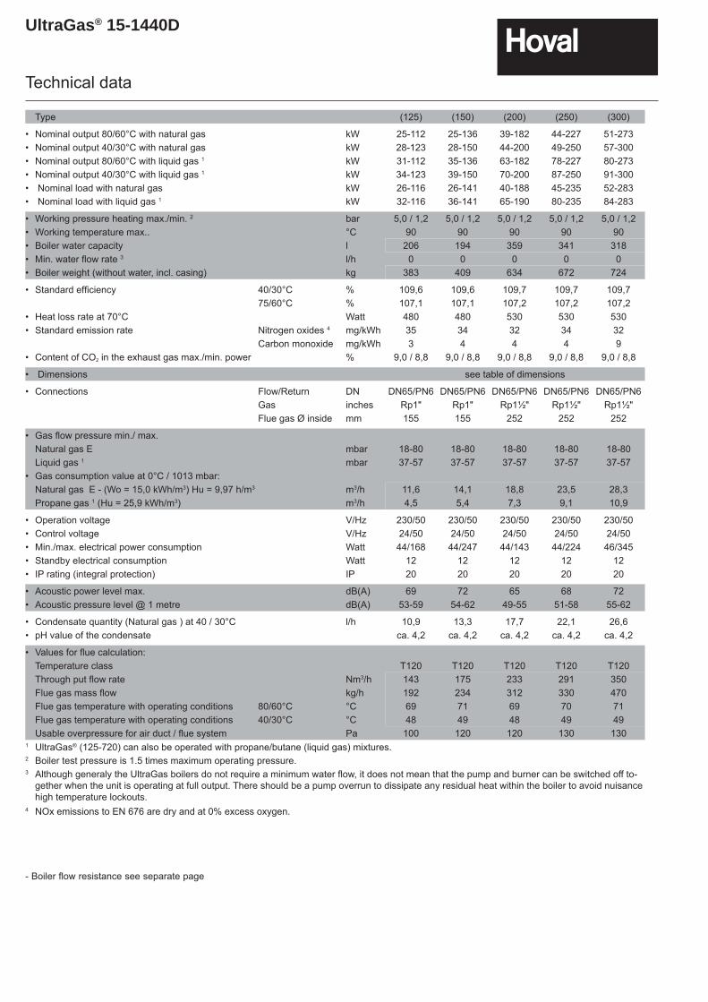
Type (125) (150) (200) (250) (300)
• Nominal output 80/60°C with natural gas kW 25-112 25-136 39-182 44-227 51-273• Nominal output 40/30°C with natural gas kW 28-123 28-150 44-200 49-250 57-300• Nominal output 80/60°C with liquid gas 1 kW 31-112 35-136 63-182 78-227 80-273• Nominal output 40/30°C with liquid gas 1 kW 34-123 39-150 70-200 87-250 91-300• Nominal load with natural gas kW 26-116 26-141 40-188 45-235 52-283• Nominal load with liquid gas 1 kW 32-116 36-141 65-190 80-235 84-283
• Working pressure heating max./min. 2 bar 5,0 / 1,2 5,0 / 1,2 5,0 / 1,2 5,0 / 1,2 5,0 / 1,2• Working temperature max.. °C 90 90 90 90 90• Boiler water capacity l 206 194 359 341 318• Min. water fl ow rate 3 l/h 0 0 0 0 0• Boiler weight (without water, incl. casing) kg 383 409 634 672 724
• Standard effi ciency 40/30°C % 109,6 109,6 109,7 109,7 109,775/60°C % 107,1 107,1 107,2 107,2 107,2
• Heat loss rate at 70°C Watt 480 480 530 530 530• Standard emission rate Nitrogen oxides 4 mg/kWh 35 34 32 34 32
Carbon monoxide mg/kWh 3 4 4 4 9• Content of CO2 in the exhaust gas max./min. power % 9,0 / 8,8 9,0 / 8,8 9,0 / 8,8 9,0 / 8,8 9,0 / 8,8
• Dimensions see table of dimensions
• Connections Flow/Return DN DN65/PN6 DN65/PN6 DN65/PN6 DN65/PN6 DN65/PN6Gas inches Rp1" Rp1" Rp1½" Rp1½" Rp1½"Flue gas Ø inside mm 155 155 252 252 252
• Gas fl ow pressure min./ max. Natural gas E mbar 18-80 18-80 18-80 18-80 18-80Liquid gas 1 mbar 37-57 37-57 37-57 37-57 37-57
• Gas consumption value at 0°C / 1013 mbar:Natural gas E - (Wo = 15,0 kWh/m3) Hu = 9,97 h/m3 m3/h 11,6 14,1 18,8 23,5 28,3Propane gas 1 (Hu = 25,9 kWh/m3) m3/h 4,5 5,4 7,3 9,1 10,9
• Operation voltage V/Hz 230/50 230/50 230/50 230/50 230/50• Control voltage V/Hz 24/50 24/50 24/50 24/50 24/50• Min./max. electrical power consumption Watt 44/168 44/247 44/143 44/224 46/345• Standby electrical consumption Watt 12 12 12 12 12• IP rating (integral protection) IP 20 20 20 20 20
• Acoustic power level max. dB(A) 69 72 65 68 72• Acoustic pressure level @ 1 metre dB(A) 53-59 54-62 49-55 51-58 55-62
• Condensate quantity (Natural gas ) at 40 / 30°C l/h 10,9 13,3 17,7 22,1 26,6• pH value of the condensate ca. 4,2 ca. 4,2 ca. 4,2 ca. 4,2 ca. 4,2
• Values for fl ue calculation: Temperature class T120 T120 T120 T120 T120Through put fl ow rate Nm3/h 143 175 233 291 350Flue gas mass fl ow kg/h 192 234 312 330 470Flue gas temperature with operating conditions 80/60°C °C 69 71 69 70 71Flue gas temperature with operating conditions 40/30°C °C 48 49 48 49 49Usable overpressure for air duct / fl ue system Pa 100 120 120 130 130
1 UltraGas® (125-720) can also be operated with propane/butane (liquid gas) mixtures.2 Boiler test pressure is 1.5 times maximum operating pressure.3 Although generaly the UltraGas boilers do not require a minimum water flow, it does not mean that the pump and burner can be switched off to-
gether when the unit is operating at full output. There should be a pump overrun to dissipate any residual heat within the boiler to avoid nuisance high temperature lockouts.
4 NOx emissions to EN 676 are dry and at 0% excess oxygen.
- Boiler fl ow resistance see separate page
UltraGas® 15-1440D
Technical data
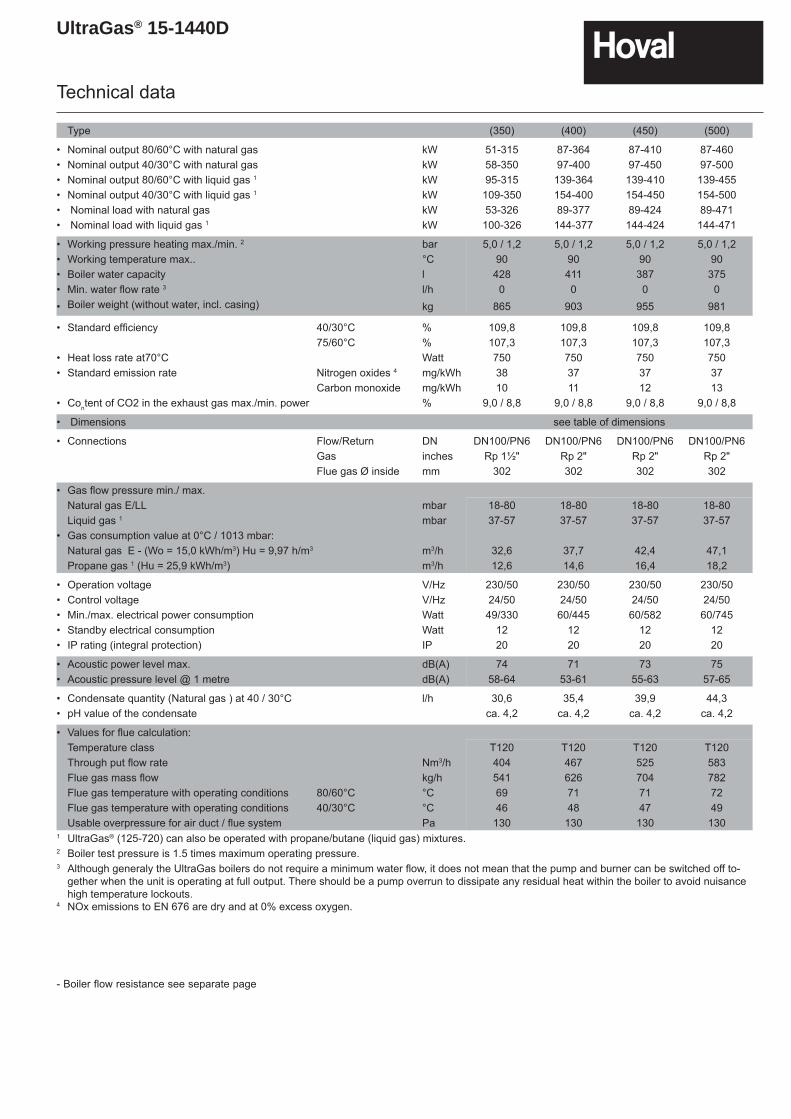
Type (350) (400) (450) (500)
• Nominal output 80/60°C with natural gas kW 51-315 87-364 87-410 87-460• Nominal output 40/30°C with natural gas kW 58-350 97-400 97-450 97-500• Nominal output 80/60°C with liquid gas 1 kW 95-315 139-364 139-410 139-455• Nominal output 40/30°C with liquid gas 1 kW 109-350 154-400 154-450 154-500• Nominal load with natural gas kW 53-326 89-377 89-424 89-471• Nominal load with liquid gas 1 kW 100-326 144-377 144-424 144-471
• Working pressure heating max./min. 2 bar 5,0 / 1,2 5,0 / 1,2 5,0 / 1,2 5,0 / 1,2• Working temperature max.. °C 90 90 90 90• Boiler water capacity l 428 411 387 375• Min. water fl ow rate 3 l/h 0 0 0 0• Boiler weight (without water, incl. casing) kg 865 903 955 981
• Standard effi ciency 40/30°C % 109,8 109,8 109,8 109,875/60°C % 107,3 107,3 107,3 107,3
• Heat loss rate at70°C Watt 750 750 750 750• Standard emission rate Nitrogen oxides 4 mg/kWh 38 37 37 37
Carbon monoxide mg/kWh 10 11 12 13• Content of CO2 in the exhaust gas max./min. power % 9,0 / 8,8 9,0 / 8,8 9,0 / 8,8 9,0 / 8,8
• Dimensions see table of dimensions
• Connections Flow/Return DN DN100/PN6 DN100/PN6 DN100/PN6 DN100/PN6Gas inches Rp 1½" Rp 2" Rp 2" Rp 2"Flue gas Ø inside mm 302 302 302 302
• Gas fl ow pressure min./ max.Natural gas E/LL mbar 18-80 18-80 18-80 18-80Liquid gas 1 mbar 37-57 37-57 37-57 37-57
• Gas consumption value at 0°C / 1013 mbar: Natural gas E - (Wo = 15,0 kWh/m3) Hu = 9,97 h/m3 m3/h 32,6 37,7 42,4 47,1Propane gas 1 (Hu = 25,9 kWh/m3) m3/h 12,6 14,6 16,4 18,2
• Operation voltage V/Hz 230/50 230/50 230/50 230/50• Control voltage V/Hz 24/50 24/50 24/50 24/50• Min./max. electrical power consumption Watt 49/330 60/445 60/582 60/745• Standby electrical consumption Watt 12 12 12 12• IP rating (integral protection) IP 20 20 20 20
• Acoustic power level max. dB(A) 74 71 73 75• Acoustic pressure level @ 1 metre dB(A) 58-64 53-61 55-63 57-65
• Condensate quantity (Natural gas ) at 40 / 30°C l/h 30,6 35,4 39,9 44,3• pH value of the condensate ca. 4,2 ca. 4,2 ca. 4,2 ca. 4,2
• Values for fl ue calculation: Temperature class T120 T120 T120 T120Through put fl ow rate Nm3/h 404 467 525 583Flue gas mass fl ow kg/h 541 626 704 782Flue gas temperature with operating conditions 80/60°C °C 69 71 71 72Flue gas temperature with operating conditions 40/30°C °C 46 48 47 49Usable overpressure for air duct / fl ue system Pa 130 130 130 130
1 UltraGas® (125-720) can also be operated with propane/butane (liquid gas) mixtures.2 Boiler test pressure is 1.5 times maximum operating pressure.3 Although generaly the UltraGas boilers do not require a minimum water flow, it does not mean that the pump and burner can be switched off to-
gether when the unit is operating at full output. There should be a pump overrun to dissipate any residual heat within the boiler to avoid nuisance high temperature lockouts.
4 NOx emissions to EN 676 are dry and at 0% excess oxygen.
- Boiler fl ow resistance see separate page
UltraGas® 15-1440D
Technical data
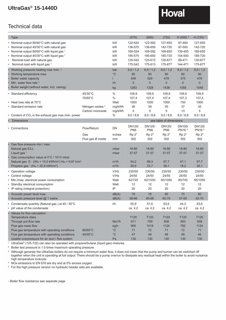
Type (575) (650) (720) H (500) 5 H (720) 5
• Nominal output 80/60°C with natural gas kW 122-524 122-592 127-655 87-460 127-655• Nominal output 40/30°C with natural gas kW 136-575 136-650 142-720 97-500 142-720• Nominal output 80/60°C with liquid gas 1 kW 169-524 169-592 169-655 139-455 169-655• Nominal output 40/30°C with liquid gas 1 kW 185-575 185-650 185-720 154-500 185-720• Nominal load with natural gas kW 125-542 125-613 130-677 89-471 130-677• Nominal load with liquid gas 1 kW 175-542 175-613 175-677 144-471 175-677
• Working pressure heating max./min. 2 bar 6,0 / 1,2 6,0 / 1,2 6,0 / 1,2 8,0 / 1,2 8,0 / 1,2• Working temperature max. °C 90 90 90 90 90• Boiler water capacity l 549 529 478 375 478• Min. water fl ow rate 3 l/h 0 0 0 0 0• Boiler weight (without water, incl. casing) kg 1283 1328 1438 1055 1548
• Standard effi ciency 40/30°C % 109,9 109,9 109,9 109,9 109,975/60°C % 107,4 107,4 107,4 107,3 107,4
• Heat loss rate at 70°C Watt 1000 1000 1000 750 1000• Standard emission rate Nitrogen oxides 4 mg/kWh 36 39 35 37 35
Carbon monoxide mg/kWh 5 5 5 13 5• Content of CO2 in the exhaust gas max./min. power % 9,0 / 8,8 9,0 / 8,8 9,0 / 8,8 9,0 / 8,8 9,0 / 8,8
• Dimensions see table of dimensions
• Connections Flow/Return DN DN125/PN6
DN125/PN6
DN125/PN6
DN100/PN16 5
DN125/PN16 5
Gas inches Rp 2" Rp 2" Rp 2" Rp 2" Rp 2"Flue gas Ø inside mm 302 302 302 302 302
• Gas fl ow pressure min./ max. Natural gas E/LL mbar 18-80 18-80 18-80 18-80 18-80Liquid gas 1 mbar 37-57 37-57 37-57 37-57 37-57
• Gas consumption value at 0°C / 1013 mbar: Natural gas E - (Wo = 15,0 kWh/m3) Hu = 9,97 h/m3 m3/h 54,2 69,3 67,7 47,1 67,7Propane gas 1 (Hu = 25,9 kWh/m3) m3/h 20,9 23,7 26,1 18,2 26,1
• Operation voltage V/Hz 230/50 230/50 230/50 230/50 230/50• Control voltage V/Hz 24/50 24/50 24/50 24/50 24/50• Min./max. electrical power consumption Watt 62/720 62/1030 65/1050 60/745 65/1050• Standby electrical consumption Watt 12 12 12 12 12• IP rating (integral protection) IP 20 20 20 20 20
• Acoustic power level max. dB(A) 76 78 80 75 80• Acoustic pressure level @ 1 metre dB(A) 58-66 60-68 62-70 57-65 62-70
• Condensate quantity (Natural gas ) at 40 / 30°C l/h 50,9 57,6 63,6 44,3 63,6• pH value of the condensate ca. 4,2 ca. 4,2 ca. 4,2 ca. 4,2 ca. 4,2
• Values for fl ue calculation: Temperature class T120 T120 T120 T120 T120Through put fl ow rate Nm3/h 671 759 838 583 838Flue gas mass fl ow kg/h 900 1018 1124 782 1124Flue gas temperature with operating conditions 80/60°C °C 71 72 71 72 71Flue gas temperature with operating conditions 40/30°C °C 47 49 46 49 46Usable overpressure for air duct / fl ue system Pa 130 130 130 130 130
1 UltraGas® (125-720) can also be operated with propane/butane (liquid gas) mixtures.2 Boiler test pressure is 1.5 times maximum operating pressure.3 Although generaly the UltraGas boilers do not require a minimum water flow, it does not mean that the pump and burner can be switched off
together when the unit is operating at full output. There should be a pump overrun to dissipate any residual heat within the boiler to avoid nuisance high temperature lockouts.
4 NOx emissions to EN 676 are dry and at 0% excess oxygen.5 For the high pressure version no hydraulic header sets are available.
- Boiler fl ow resistance see separate page
UltraGas® 15-1440D
Technical data
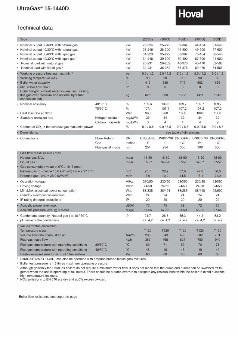
Type (250D) (300D) (400D) (500D) (600D)
• Nominal output 80/60°C with natural gas kW 25-224 25-272 39-364 44-454 51-546• Nominal output 40/30°C with natural gas kW 28-246 28-300 44-400 49-500 57-600• Nominal output 80/60°C with liquid gas 1 kW 31-223 35-272 63-364 78-454 80-546• Nominal output 40/30°C with liquid gas 1 kW 34-246 39-300 70-400 87-500 91-600• Nominal load with natural gas kW 26-231 26-282 40-376 45-470 52-566• Nominal load with liquid gas 1 kW 32-231 36-282 65-376 80-470 84-566
• Working pressure heating max./min. 2 bar 5,0 / 1,2 5,0 / 1,2 5,0 / 1,2 5,0 / 1,2 5,0 / 1,2• Working temperature max. °C 90 90 90 90 90• Boiler water capacity l 412 388 719 682 636• Min. water fl ow rate 3 l/h 0 0 0 0 0
•Boiler weight (without water volume, incl. casing,fl ue gas over pressure and optional hydraulicconnection set)
kg 828 880 1335 1411 1515
• Nominal effi ciency 40/30°C % 109,6 109,6 109,7 109,7 109,775/60°C % 107,1 107,1 107,2 107,2 107,2
• Heat loss rate at 70°C Watt 960 960 1060 1060 1060• Standard emission rate Nitrogen oxides 4 mg/kWh 35 34 32 34 32
Carbon monoxide mg/kWh 3 4 4 4 9• Content of CO2 in the exhaust gas max./min. power % 9,0 / 8,8 9,0 / 8,8 9,0 / 8,8 9,0 / 8,8 9,0 / 8,8
• Dimensions: see table of dimensions
• Connections Flow- Return DN DN80/PN6 DN80/PN6 DN80/PN6 DN80/PN6 DN80/PN6Gas inches 1“ 1“ 1½“ 1½“ 1½“Flue gas Ø inside mm 254 254 306 306 306
• Gas fl ow pressure min./ max.Natural gas E/LL mbar 18-80 18-80 18-80 18-80 18-80Liquid gas 1 mbar 37-57 37-57 37-57 37-57 37-57
• Gas consumption value at 0°C / 1013 mbar:Natural gas E - (Wo = 15,0 kWh/m3) Hu = 9,97 h/m3 m3/h 23,1 28,2 37,6 47,0 56,6Propane gas 1 (Hu = 25,9 kWh/m3) m3/h 8,9 10,9 14,5 18,1 21,9
• Operation voltage V/Hz 230/50 230/50 230/50 230/50 230/50• Driving voltage V/Hz 24/50 24/50 24/50 24/50 24/50• Min./Max. electrical power consumption Watt 88/336 88/494 88/286 88/448 92/690• Standby electrical consumption Watt 24 24 24 24 24• IP rating (integral protection) IP 20 20 20 20 20
• Acoustic power level max. dB(A) 72 75 69 72 75• Acoustic pressure level @ 1 metre dB(A) 57-65 57-65 53-59 56-62 57-65
• Condensate quantity (Natural gas ) at 40 / 30°C l/h 21,7 26,5 35,3 44,2 53,2• pH value of the condensate ca. 4,2 ca. 4,2 ca. 4,2 ca. 4,2 ca. 4,2
• Values for fl ue calculation: Temperature class T120 T120 T120 T120 T120Volume fl ow rate combustion air Nm3/h 286 349 465 582 701Flue gas mass fl ow kg/h 383 468 624 780 940Flue gas temperature with operating conditions 80/60°C °C 69 71 69 70 71Flue gas temperature with operating conditions 40/30°C °C 48 49 48 49 49Usable overpressure for air duct / fl ue system Pa 60 60 60 60 60
1 UltraGas® (250D-1440D) can also be operated with propane/butane (liquid gas) mixtures.2 Boiler test pressure is 1.5 times maximum operating pressure.3 Although generaly the UltraGas boilers do not require a minimum water flow, it does not mean that the pump and burner can be switched off to-
gether when the unit is operating at full output. There should be a pump overrun to dissipate any residual heat within the boiler to avoid nuisance high temperature lockouts.
4 NOx emissions to EN 676 are dry and at 0% excess oxygen.
- Boiler fl ow resistance see separate page
UltraGas® 15-1440D
Technical data
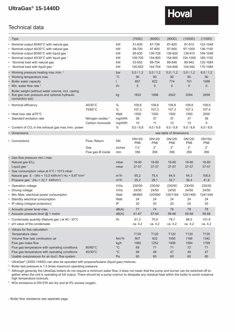
Type (700D) (800D) (900D) (1000D) (1150D)
• Nominal output 80/60°C with natural gas kW 51-630 87-728 87-820 87-910 122-1048• Nominal output 40/30°C with natural gas kW 58-700 97-800 97-900 97-1000 136-1150• Nominal output 80/60°C with liquid gas 1 kW 95-630 139-728 139-820 139-910 169-1048• Nominal output 40/30°C with liquid gas 1 kW 109-700 154-800 154-900 154-1000 185-1150• Nominal load with natural gas kW 53-652 89-754 89-848 89-942 125-1084• Nominal load with liquid gas 1 kW 100-652 144-754 144-848 144-942 175-1084
• Working pressure heating max./min. 2 bar 5,0 / 1,2 5,0 / 1,2 5,0 / 1,2 5,0 / 1,2 6,0 / 1,2• Working temperature max. °C 90 90 90 90 90• Boiler water capacity l 857 822 774 751 1098• Min. water fl ow rate 3 l/h 0 0 0 0 0
•Boiler weight (without water volume, incl. casing,fl ue gas over pressure and optional hydraulic connection set)
kg 1822 1898 2002 2054 2658
• Nominal effi ciency 40/30°C % 109,8 109,8 109,8 109,8 109,975/60°C % 107,3 107,3 107,3 107,3 107,4
• Heat loss rate at70°C Watt 1500 1500 1500 1500 2000• Standard emission rate Nitrogen oxides 4 mg/kWh 38 37 37 37 36
Carbon monoxide mg/kWh 10 11 12 13 5• Content of CO2 in the exhaust gas max./min. power % 9,0 / 8,8 9,0 / 8,8 9,0 / 8,8 9,0 / 8,8 9,0 / 8,8
• Dimensions: see table of dimensions
• Connections Flow- Return DN DN125/PN6
DN125/PN6
DN125/PN6
DN125/PN6
DN150/PN6
Gas inches 1½“ 2“ 2“ 2“ 2“Flue gas Ø inside mm 356 356 356 356 356
• Gas fl ow pressure min./ max.Natural gas E/LL mbar 18-80 18-80 18-80 18-80 18-80Liquid gas 1 mbar 37-57 37-57 37-57 37-57 37-57
• Gas consumption value at 0°C / 1013 mbar:Natural gas E - (Wo = 15,0 kWh/m3) Hu = 9,97 h/m3 m3/h 65,2 75,4 84,9 94,3 108,5Propane gas 1 (Hu = 32,7 kWh/m3) m3/h 25,2 29,1 32,7 36,4 41,9
• Operation voltage V/Hz 230/50 230/50 230/50 230/50 230/50• Driving voltage V/Hz 24/50 24/50 24/50 24/50 24/50• Min./Max. electrical power consumption Watt 98/660 120/890 120/1164 120/1490 124/1440• Standby electrical consumption Watt 24 24 24 24 24• IP rating (integral protection) IP 20 20 20 20 20
• Acoustic power level max. dB(A) 77 74 76 78 78• Acoustic pressure level @ 1 metre dB(A) 61-67 57-64 58-66 59-68 59-68
• Condensate quantity (Natural gas ) at 40 / 30°C l/h 61,3 70,9 79,7 88,5 101,9• pH value of the condensate ca. 4,2 ca. 4,2 ca. 4,2 ca. 4,2 ca. 4,2
• Values for fl ue calculation: Temperature class T120 T120 T120 T120 T120Volume fl ow rate combustion air Nm3/h 807 933 1050 1166 1342Flue gas mass fl ow kg/h 1082 1252 1408 1564 1799Flue gas temperature with operating conditions 80/60°C °C 69 71 71 72 71Flue gas temperature with operating conditions 40/30°C °C 46 48 47 49 47Usable overpressure for air duct / fl ue system Pa 60 60 60 60 60
1 UltraGas® (250D-1440D) can also be operated with propane/butane (liquid gas) mixtures.2 Boiler test pressure is 1.5 times maximum operating pressure.3 Although generaly the UltraGas boilers do not require a minimum water flow, it does not mean that the pump and burner can be switched off to-
gether when the unit is operating at full output. There should be a pump overrun to dissipate any residual heat within the boiler to avoid nuisance high temperature lockouts.
4 NOx emissions to EN 676 are dry and at 0% excess oxygen.
- Boiler fl ow resistance see separate page
UltraGas® 15-1440D
Technical data
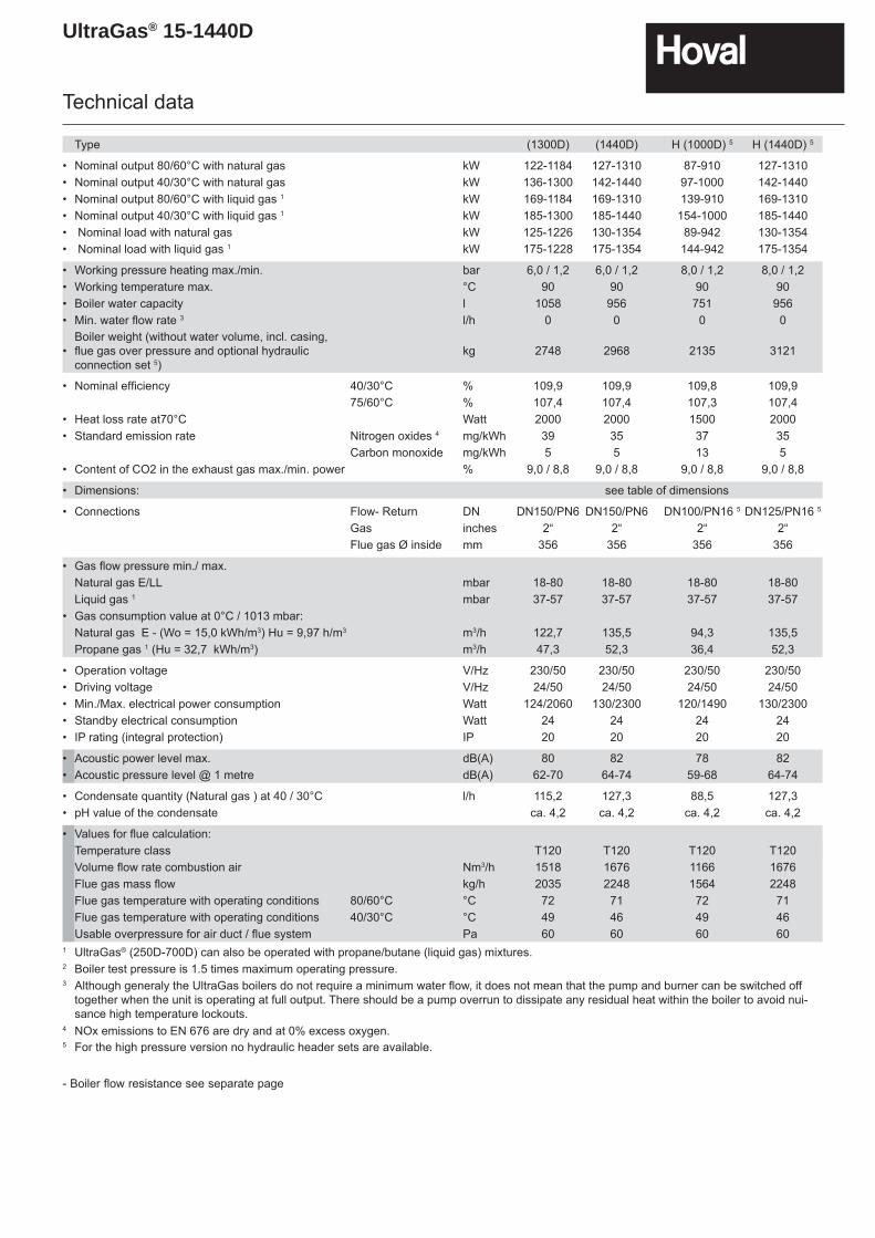
Type (1300D) (1440D) H (1000D) 5 H (1440D) 5
• Nominal output 80/60°C with natural gas kW 122-1184 127-1310 87-910 127-1310• Nominal output 40/30°C with natural gas kW 136-1300 142-1440 97-1000 142-1440• Nominal output 80/60°C with liquid gas 1 kW 169-1184 169-1310 139-910 169-1310• Nominal output 40/30°C with liquid gas 1 kW 185-1300 185-1440 154-1000 185-1440• Nominal load with natural gas kW 125-1226 130-1354 89-942 130-1354• Nominal load with liquid gas 1 kW 175-1228 175-1354 144-942 175-1354
• Working pressure heating max./min. bar 6,0 / 1,2 6,0 / 1,2 8,0 / 1,2 8,0 / 1,2• Working temperature max. °C 90 90 90 90• Boiler water capacity l 1058 956 751 956• Min. water fl ow rate 3 l/h 0 0 0 0
•Boiler weight (without water volume, incl. casing,fl ue gas over pressure and optional hydraulicconnection set 5)
kg 2748 2968 2135 3121
• Nominal effi ciency 40/30°C % 109,9 109,9 109,8 109,975/60°C % 107,4 107,4 107,3 107,4
• Heat loss rate at70°C Watt 2000 2000 1500 2000• Standard emission rate Nitrogen oxides 4 mg/kWh 39 35 37 35
Carbon monoxide mg/kWh 5 5 13 5• Content of CO2 in the exhaust gas max./min. power % 9,0 / 8,8 9,0 / 8,8 9,0 / 8,8 9,0 / 8,8
• Dimensions: see table of dimensions
• Connections Flow- Return DN DN150/PN6 DN150/PN6 DN100/PN16 5 DN125/PN16 5
Gas inches 2“ 2“ 2“ 2“Flue gas Ø inside mm 356 356 356 356
• Gas fl ow pressure min./ max.Natural gas E/LL mbar 18-80 18-80 18-80 18-80Liquid gas 1 mbar 37-57 37-57 37-57 37-57
• Gas consumption value at 0°C / 1013 mbar:Natural gas E - (Wo = 15,0 kWh/m3) Hu = 9,97 h/m3 m3/h 122,7 135,5 94,3 135,5Propane gas 1 (Hu = 32,7 kWh/m3) m3/h 47,3 52,3 36,4 52,3
• Operation voltage V/Hz 230/50 230/50 230/50 230/50• Driving voltage V/Hz 24/50 24/50 24/50 24/50• Min./Max. electrical power consumption Watt 124/2060 130/2300 120/1490 130/2300• Standby electrical consumption Watt 24 24 24 24• IP rating (integral protection) IP 20 20 20 20
• Acoustic power level max. dB(A) 80 82 78 82• Acoustic pressure level @ 1 metre dB(A) 62-70 64-74 59-68 64-74
• Condensate quantity (Natural gas ) at 40 / 30°C l/h 115,2 127,3 88,5 127,3• pH value of the condensate ca. 4,2 ca. 4,2 ca. 4,2 ca. 4,2
• Values for fl ue calculation: Temperature class T120 T120 T120 T120Volume fl ow rate combustion air Nm3/h 1518 1676 1166 1676Flue gas mass fl ow kg/h 2035 2248 1564 2248Flue gas temperature with operating conditions 80/60°C °C 72 71 72 71Flue gas temperature with operating conditions 40/30°C °C 49 46 49 46Usable overpressure for air duct / fl ue system Pa 60 60 60 60
1 UltraGas® (250D-700D) can also be operated with propane/butane (liquid gas) mixtures.2 Boiler test pressure is 1.5 times maximum operating pressure.3 Although generaly the UltraGas boilers do not require a minimum water flow, it does not mean that the pump and burner can be switched off
together when the unit is operating at full output. There should be a pump overrun to dissipate any residual heat within the boiler to avoid nui-sance high temperature lockouts.
4 NOx emissions to EN 676 are dry and at 0% excess oxygen.5 For the high pressure version no hydraulic header sets are available.
- Boiler fl ow resistance see separate page
UltraGas® 15-1440D
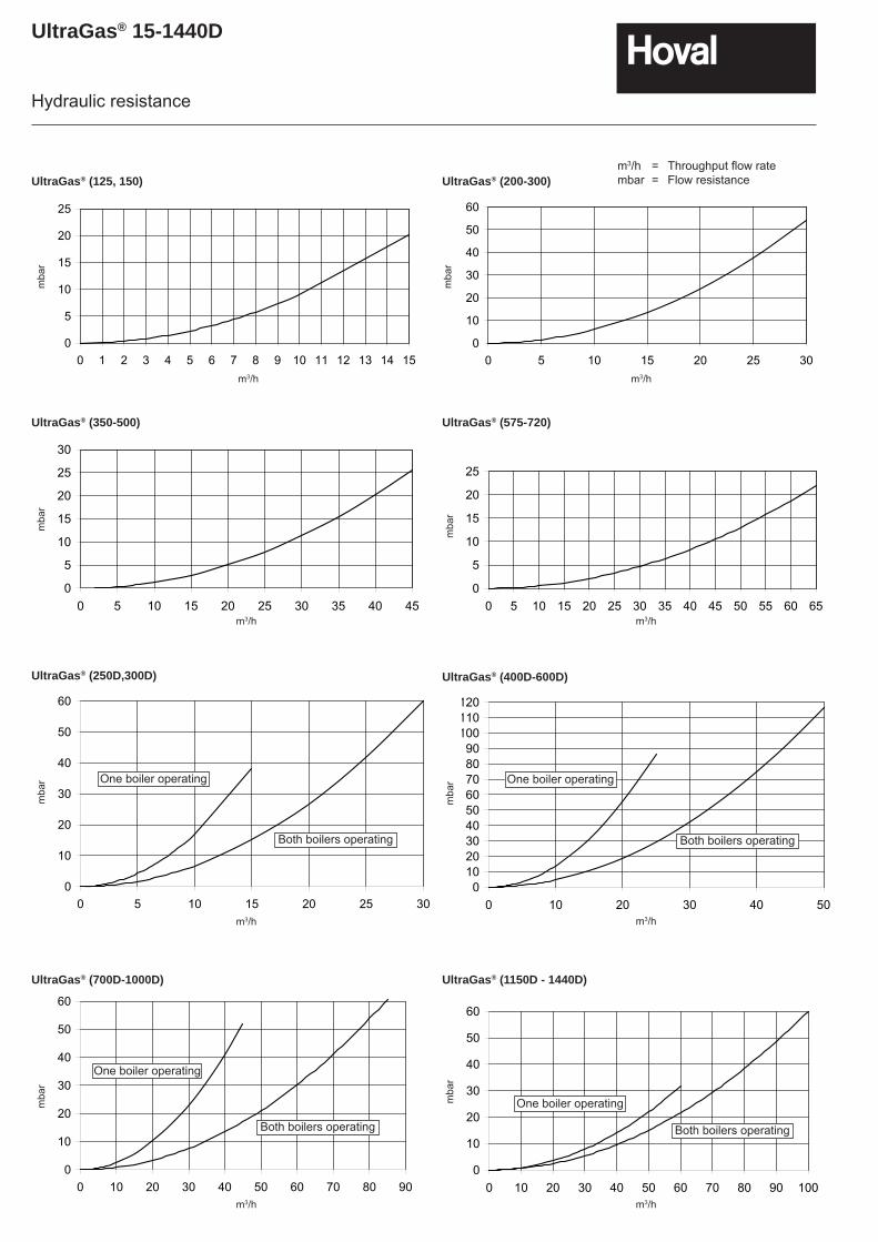
Hydraulic resistance
m3/h = Throughput fl ow ratembar = Flow resistance
0102030405060708090
100110120
0 10 20 30 40 50
0
10
20
30
40
50
60
0 10 20 30 40 50 60 70 80 900
10
20
30
40
50
60
0 10 20 30 40 50 60 70 80 90 100
0
10
20
30
40
50
60
0 5 10 15 20 25 30
UltraGas® (250D,300D) UltraGas® (400D-600D)
UltraGas® (700D-1000D) UltraGas® (1150D - 1440D)
One boiler operating
Both boilers operating
One boiler operating
Both boilers operating
One boiler operating
Both boilers operating
One boiler operating
Both boilers operating
0
5
10
15
20
25
0 5 10 15 20 25 30 35 40 45 50 55 60 650
5
10
15
20
25
30
0 5 10 15 20 25 30 35 40 45
UltraGas® (350-500) UltraGas® (575-720)
mba
r
m3/h
mba
r
m3/h
UltraGas® (125, 150) UltraGas® (200-300)
0
10
20
30
40
50
60
0 5 10 15 20 25 300
5
10
15
20
25
0 1 2 3 4 5 6 7 8 9 10 11 12 13 14 15
mba
r
m3/h
mba
r
m3/h
mba
r
m3/h
m3/h
mba
r
mba
rm
bar
m3/h
m3/h
UltraGas® 15-1440D
9
10 10
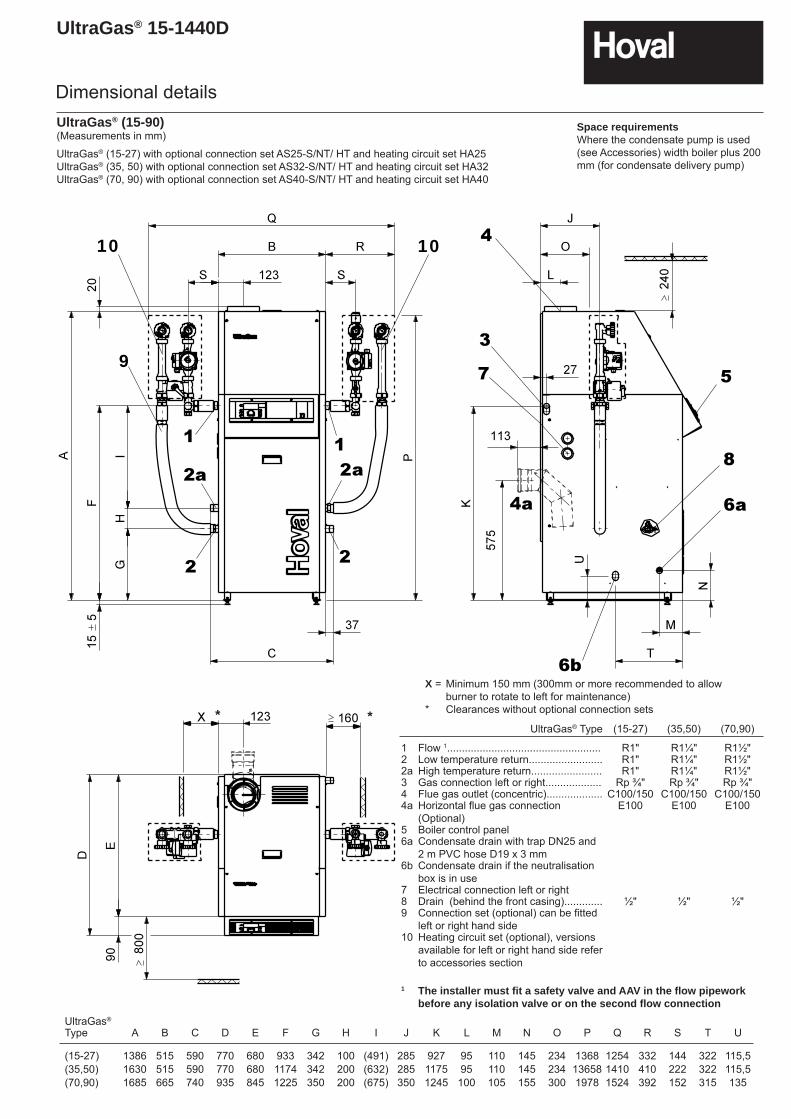
UltraGas® (15-27) with optional connection set AS25-S/NT/ HT and heating circuit set HA25UltraGas® (35, 50) with optional connection set AS32-S/NT/ HT and heating circuit set HA32UltraGas® (70, 90) with optional connection set AS40-S/NT/ HT and heating circuit set HA40
Dimensional details
UltraGas® Type (15-27) (35,50) (70,90)
1 Flow 1.................................................... R1" R1¼" R1½"2 Low temperature return......................... R1" R1¼" R1½"2a High temperature return........................ R1" R1¼" R1½"3 Gas connection left or right................... Rp ¾" Rp ¾" Rp ¾"4 Flue gas outlet (concentric)................... C100/150 C100/150 C100/1504a Horizontal fl ue gas connection
(Optional)E100 E100 E100
5 Boiler control panel6a Condensate drain with trap DN25 and
2 m PVC hose D19 x 3 mm6b Condensate drain if the neutralisation
box is in use7 Electrical connection left or right8 Drain (behind the front casing)............. ½" ½" ½"9 Connection set (optional) can be fi tted
left or right hand side10 Heating circuit set (optional), versions
available for left or right hand side refer to accessories section
1 The installer must fi t a safety valve and AAV in the fl ow pipework before any isolation valve or on the second fl ow connection
X = Minimum 150 mm (300mm or more recommended to allow burner to rotate to left for maintenance)
* Clearances without optional connection sets
UltraGas®
Type A B C D E F G H I J K L M N O P Q R S T U
(15-27) 1386 515 590 770 680 933 342 100 (491) 285 927 95 110 145 234 1368 1254 332 144 322 115,5(35,50) 1630 515 590 770 680 1174 342 200 (632) 285 1175 95 110 145 234 13658 1410 410 222 322 115,5(70,90) 1685 665 740 935 845 1225 350 200 (675) 350 1245 100 105 155 300 1978 1524 392 152 315 135
UltraGas® (15-90)(Measurements in mm)
* *
Space requirementsWhere the condensate pump is used (see Accessories) width boiler plus 200 mm (for condensate delivery pump)
UltraGas® 15-1440D
Dimensional details
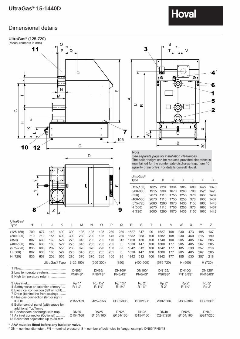
UltraGas® (125-720)(Measurements in mm)
UltraGas® Type (125,150) (200-300) (350) (400-500) (575-720) H (500) H (720)
1 Flow.................................................. DN65/ PN6/4S*
DN65/ PN6/4S*
DN100/ PN6/4S*
DN100/ PN6/4S*
DN125/ PN6/8S*
DN100/PN16/8S*
DN125/PN16/8S*2 Low temperature return....................
5 High temperature return...................
3 Gas inlet........................................... Rp 1" Rp 1½" Rp 1½" Rp 2" Rp 2" Rp 2" Rp 2"4 Safety valve or calorifi er primary 1... R 1½" R 1½" R 1½" R 1½" R 2" R 1½" Rp 2"6 Electrical connection (left or right)....7 Drain (behind the front casing).........8 Flue gas connection (left or right)
ID/OD............................................... Ø155/159 Ø252/256 Ø302/306 Ø302/306 Ø302/306 Ø302/306 Ø302/3069 Boiler control panel (with space for
additional TopTronic10 Condensate discharge with trap...... DN25 DN25 DN25 DN25 DN40 DN25 DN4011 Air inlet connector (Optional) .......... Ø154/160 Ø154/160 Ø154/160 Ø154/160 Ø247/250 Ø154/160 Ø247/25012 Boiler feet adjustable up to 80 mm
1 AAV must be fi tted before any isolation valve.* DN = nominal diameter , PN = nominal pressure, S = number of bolt holes in fl ange, example DN65/ PN6/4S
UltraGas®
Type A B C D E F G
(125,150) 1825 820 1334 985 680 1427 1378(200-300) 1915 930 1670 1260 790 1525 1420(350) 2070 1110 1755 1255 970 1660 1437(400-500) 2070 1110 1755 1255 970 1660 1437(575-720) 2080 1290 1970 1435 1150 1660 1443H (500) 2070 1110 1755 1255 970 1660 1437H (720) 2080 1290 1970 1435 1150 1660 1443
UltraGas®
Type H I J K L M N O P Q R S T U V W X Y Z
(125,150) 700 677 143 490 300 198 198 198 280 230 1627 347 90 1627 108 230 473 195 137(200-300) 710 710 155 490 300 280 200 185 145 230 1682 368 100 1682 108 230 460 215 190(350) 807 630 160 527 275 345 205 205 170 312 1720 430 100 1740 100 205 485 267 205(400-500) 807 630 160 527 275 345 205 205 205 0 1830 447 100 1800 177 205 485 267 205(575-720) 835 608 202 555 280 370 370 220 100 85 1842 512 100 1842 177 185 530 357 218H (500) 807 630 160 527 275 345 205 205 205 0 1830 447 100 1800 177 205 485 267 205H (720) 835 608 202 555 280 370 370 220 100 85 1842 512 100 1842 177 185 530 357 218
Note:See separate page for installation clearances. The boiler height can be reduced provided clearance is maintained for the condensate discharge trap, item 10 (gravity drain only). For details consult Hoval.
1
UltraGas® 15-1440D
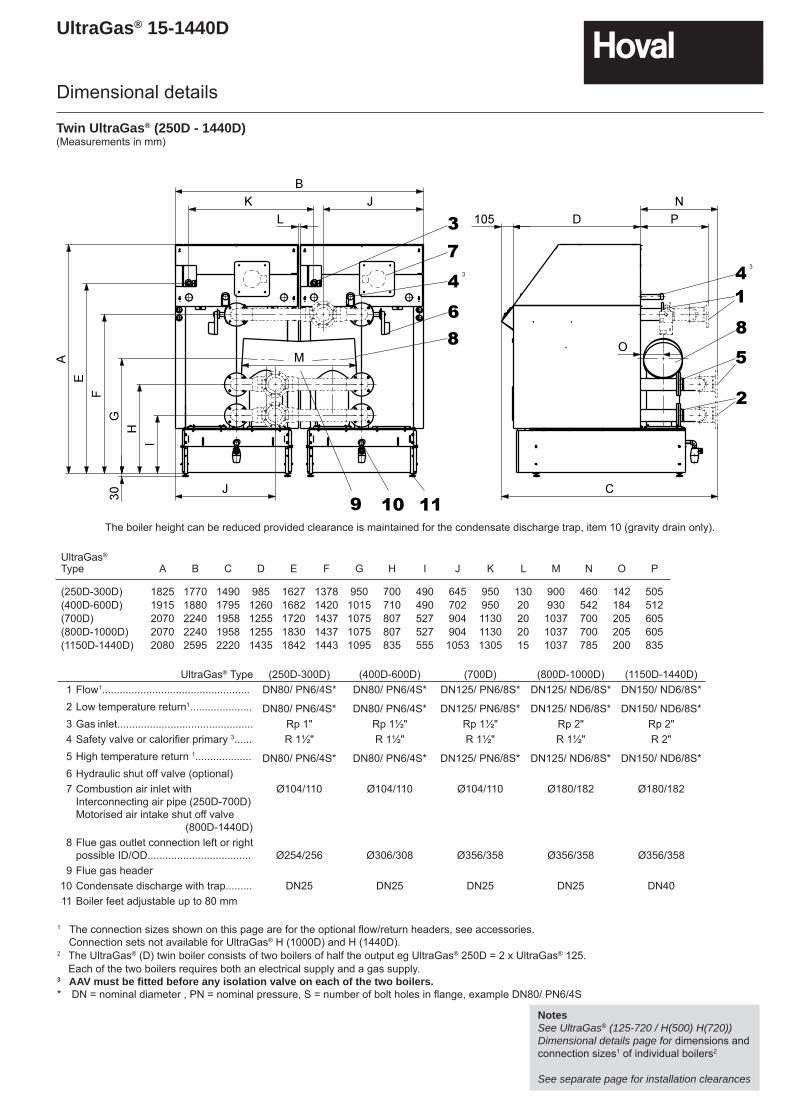
NotesSee UltraGas® (125-720 / H(500) H(720)) Dimensional details page for dimensions and connection sizes1 of individual boilers2
See separate page for installation clearances
Twin UltraGas® (250D - 1440D)(Measurements in mm)
UltraGas® Type (250D-300D) (400D-600D) (700D) (800D-1000D) (1150D-1440D)1 Flow1.................................................. DN80/ PN6/4S* DN80/ PN6/4S* DN125/ PN6/8S* DN125/ ND6/8S* DN150/ ND6/8S*2 Low temperature return1..................... DN80/ PN6/4S* DN80/ PN6/4S* DN125/ PN6/8S* DN125/ ND6/8S* DN150/ ND6/8S*3 Gas inlet.............................................. Rp 1" Rp 1½" Rp 1½" Rp 2" Rp 2"4 Safety valve or calorifi er primary 3...... R 1½" R 1½" R 1½" R 1½" R 2"5 High temperature return 1................... DN80/ PN6/4S* DN80/ PN6/4S* DN125/ PN6/8S* DN125/ ND6/8S* DN150/ ND6/8S*6 Hydraulic shut off valve (optional)7 Combustion air inlet with
Interconnecting air pipe (250D-700D)Motorised air intake shut off valve (800D-1440D)
Ø104/110 Ø104/110 Ø104/110 Ø180/182 Ø180/182
8 Flue gas outlet connection left or right possible ID/OD................................... Ø254/256 Ø306/308 Ø356/358 Ø356/358 Ø356/358
9 Flue gas header10 Condensate discharge with trap......... DN25 DN25 DN25 DN25 DN4011 Boiler feet adjustable up to 80 mm
1 The connection sizes shown on this page are for the optional fl ow/return headers, see accessories. Connection sets not available for UltraGas® H (1000D) and H (1440D).2 The UltraGas® (D) twin boiler consists of two boilers of half the output eg UltraGas® 250D = 2 x UltraGas® 125.
Each of the two boilers requires both an electrical supply and a gas supply.3 AAV must be fi tted before any isolation valve on each of the two boilers.* DN = nominal diameter , PN = nominal pressure, S = number of bolt holes in fl ange, example DN80/ PN6/4S
UltraGas®
Type A B C D E F G H I J K L M N O P
(250D-300D) 1825 1770 1490 985 1627 1378 950 700 490 645 950 130 900 460 142 505(400D-600D) 1915 1880 1795 1260 1682 1420 1015 710 490 702 950 20 930 542 184 512(700D) 2070 2240 1958 1255 1720 1437 1075 807 527 904 1130 20 1037 700 205 605(800D-1000D) 2070 2240 1958 1255 1830 1437 1075 807 527 904 1130 20 1037 700 205 605(1150D-1440D) 2080 2595 2220 1435 1842 1443 1095 835 555 1053 1305 15 1037 785 200 835
Dimensional details
The boiler height can be reduced provided clearance is maintained for the condensate discharge trap, item 10 (gravity drain only).
33
UltraGas® 15-1440D
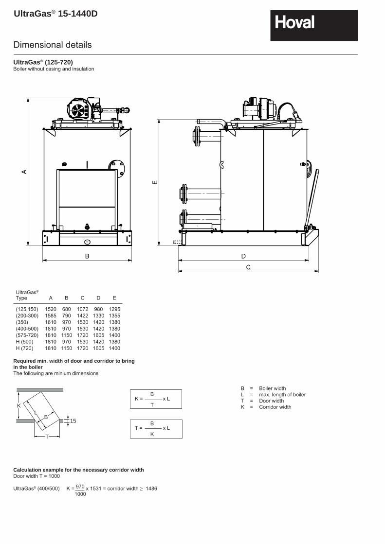
Required min. width of door and corridor to bringin the boilerThe following are minium dimensions
15
KL
B
T
B K = x L T
B T = x L K
B = Boiler widthL = max. length of boilerT = Door widthK = Corridor width
Calculation example for the necessary corridor widthDoor width T = 1000
UltraGas® (400/500) K = 970 x 1531 = corridor width ≥ 1486 1000
UltraGas® (125-720)Boiler without casing and insulation
UltraGas®
Type A B C D E
(125,150) 1520 680 1072 980 1295(200-300) 1585 790 1422 1330 1355(350) 1610 970 1530 1420 1380(400-500) 1810 970 1530 1420 1380(575-720) 1810 1150 1720 1605 1400H (500) 1810 970 1530 1420 1380H (720) 1810 1150 1720 1605 1400
Dimensional details
UltraGas® 15-1440D
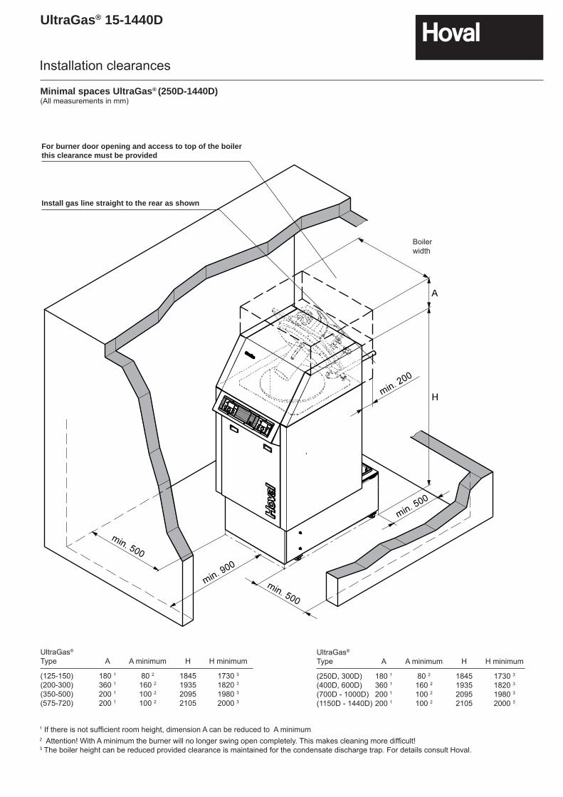
Minimal spaces UltraGas® (250D-1440D)(All measurements in mm)
For burner door opening and access to top of the boiler this clearance must be provided
Install gas line straight to the rear as shown
UltraGas®
Type A A minimum H H minimum
(125-150) 180 1 80 2 1845 1730 3
(200-300) 360 1 160 2 1935 1820 3
(350-500) 200 1 100 2 2095 1980 3
(575-720) 200 1 100 2 2105 2000 3
UltraGas®
Type A A minimum H H minimum
(250D, 300D) 180 1 80 2 1845 1730 3
(400D, 600D) 360 1 160 2 1935 1820 3
(700D - 1000D) 200 1 100 2 2095 1980 3
(1150D - 1440D) 200 1 100 2 2105 2000 3
1 If there is not suffi cient room height, dimension A can be reduced to A minimum2 Attention! With A minimum the burner will no longer swing open completely. This makes cleaning more difficult! 3 The boiler height can be reduced provided clearance is maintained for the condensate discharge trap. For details consult Hoval.
Installation clearances
Boiler width
UltraGas® 15-1440D
Ventilation
For installations not exceeding 70 kW total nominal input1 (net) refer to BS5440-2 : 2000.
For installations over 70 kW total nominal input1 (net) both high and low level ventilation is required, this should be calculated toBS6644 : current edition.
1 See Technical data section of this booklet.
Flue system / ventilationM
ax fl
ue h
eigh
t (m
)
Horizontal flue gas pipe length (m)Horizontal flue gas pipe length (m)
0
5
10
15
20
25
30
35
40
0 1 2 3 4 5 6
0
4
8
12
16
20
24
0 1 2 3 4 5 6
UltraGas 15 - 50
UltraGas 70
UltraGas 90
UltraGas 50
UltraGas 70
UltraGas 15 - 35
Max
flue
hei
ght (
m)
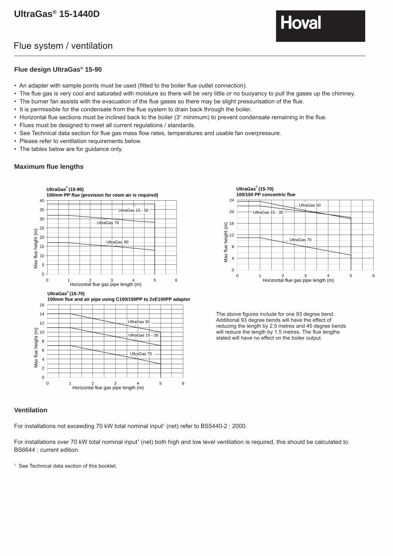
UltraGas (15-90)100mm PP flue (provision for room air is required)
UltraGas (15-70)100/150 PP concentric flue
®
0
2
4
6
8
10
12
14
16
0 1 2 3 4 5 6
UltraGas 15 - 35
UltraGas 50
UltraGas 70
Horizontal flue gas pipe length (m)
Max
flue
hei
ght (
m)
UltraGas (15-70)100mm flue and air pipe using C100/150PP to 2xE100PP adaptor
®
®
Flue design UltraGas® 15-90
• An adapter with sample points must be used (fi tted to the boiler fl ue outlet connection).• The fl ue gas is very cool and saturated with moisture so there will be very little or no buoyancy to pull the gases up the chimney.• The burner fan assists with the evacuation of the fl ue gases so there may be slight pressurisation of the fl ue.• It is permissible for the condensate from the fl ue system to drain back through the boiler.• Horizontal fl ue sections must be inclined back to the boiler (3° minimum) to prevent condensate remaining in the fl ue.• Flues must be designed to meet all current regulations / standards.• See Technical data section for fl ue gas mass fl ow rates, temperatures and usable fan overpressure.• Please refer to ventilation requirements below.• The tables below are for guidance only.
Maximum fl ue lengths
The above fi gures include for one 93 degree bend. Additional 93 degree bends will have the effect of reducing the length by 2.5 metres and 45 degree bends will reduce the length by 1.5 metres. The fl ue lengths stated will have no effect on the boiler output.
UltraGas® 15-1440D
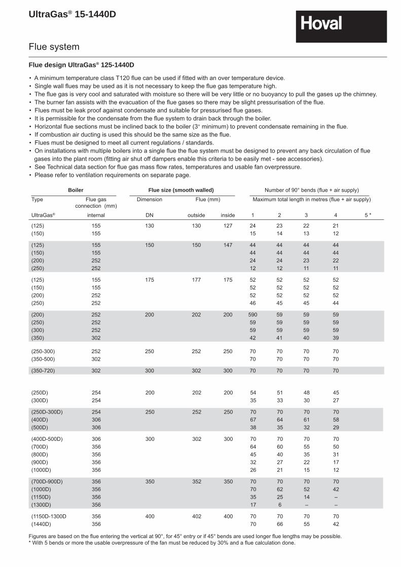
Boiler Flue size (smooth walled) Number of 90° bends (fl ue + air supply)
Type Flue gas connection (mm)
Dimension Flue (mm) Maximum total length in metres (fl ue + air supply)
UltraGas® internal DN outside inside 1 2 3 4 5 *
(125) 155 130 130 127 24 23 22 21(150) 155 15 14 13 12
(125) 155 150 150 147 44 44 44 44(150) 155 44 44 44 44(200) 252 24 24 23 22(250) 252 12 12 11 11
(125) 155 175 177 175 52 52 52 52(150) 155 52 52 52 52(200) 252 52 52 52 52(250) 252 46 45 45 44
(200) 252 200 202 200 590 59 59 59(250) 252 59 59 59 59(300) 252 59 59 59 59(350) 302 42 41 40 39
(250-300) 252 250 252 250 70 70 70 70(350-500) 302 70 70 70 70
(350-720) 302 300 302 300 70 70 70 70
• A minimum temperature class T120 fl ue can be used if fi tted with an over temperature device.• Single wall fl ues may be used as it is not necessary to keep the fl ue gas temperature high.• The fl ue gas is very cool and saturated with moisture so there will be very little or no buoyancy to pull the gases up the chimney.• The burner fan assists with the evacuation of the fl ue gases so there may be slight pressurisation of the fl ue.• Flues must be leak proof against condensate and suitable for pressurised fl ue gases.• It is permissible for the condensate from the fl ue system to drain back through the boiler.• Horizontal fl ue sections must be inclined back to the boiler (3° minimum) to prevent condensate remaining in the fl ue.• If combustion air ducting is used this should be the same size as the fl ue.• Flues must be designed to meet all current regulations / standards.• On installations with multiple boilers into a single fl ue the fl ue system must be designed to prevent any back circulation of fl ue gases into the plant room (fi tting air shut off dampers enable this criteria to be easily met - see accessories).• See Technical data section for fl ue gas mass fl ow rates, temperatures and usable fan overpressure.• Please refer to ventilation requirements on separate page.
Flue system
Flue design UltraGas® 125-1440D
(250D) 254 200 202 200 54 51 48 45(300D) 254 35 33 30 27
(250D-300D) 254 250 252 250 70 70 70 70(400D) 306 67 64 61 58(500D) 306 38 35 32 29
(400D-500D) 306 300 302 300 70 70 70 70(700D) 356 64 60 55 50(800D) 356 45 40 35 31(900D) 356 32 27 22 17(1000D) 356 26 21 15 12
(700D-900D) 356 350 352 350 70 70 70 70(1000D) 356 70 62 52 42(1150D) 356 35 25 14 –(1300D) 356 17 6 – –
(1150D-1300D 356 400 402 400 70 70 70 70(1440D) 356 70 66 55 42
Figures are based on the fl ue entering the vertical at 90°, for 45° entry or if 45° bends are used longer fl ue lengths may be possible.* With 5 bends or more the usable overpressure of the fan must be reduced by 30% and a flue calculation done.
UltraGas® 15-1440D
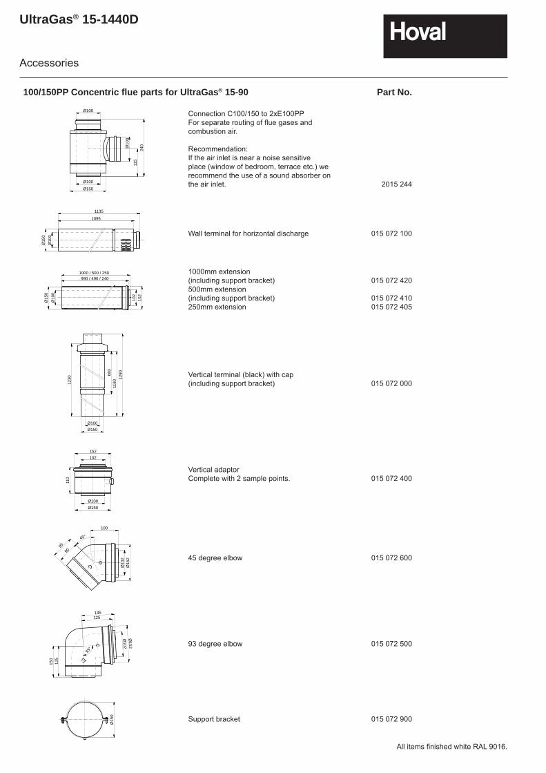
100/150PP Concentric fl ue parts for UltraGas® 15-90 Part No.
Connection C100/150 to 2xE100PPFor separate routing of fl ue gases and combustion air.
Recommendation:If the air inlet is near a noise sensitive place (window of bedroom, terrace etc.) we recommend the use of a sound absorber on the air inlet. 2015 244
Wall terminal for horizontal discharge 015 072 100
1000mm extension(including support bracket)500mm extension(including support bracket)250mm extension
015 072 420
015 072 410015 072 405
Vertical terminal (black) with cap(including support bracket) 015 072 000
Vertical adaptor Complete with 2 sample points. 015 072 400
45 degree elbow 015 072 600
93 degree elbow 015 072 500
Support bracket 015 072 900
152
102
990 / 490 / 2401000 / 500 / 250
Ø10
0
Ø15
0
Ø10
0
Ø100
Ø150
Ø100
115
240
Ø10
0Ø
150
1095
1135
1230
Ø100Ø150
680
1180
1290
102152
110
Ø100Ø150
Ø10
2Ø
152
9095
100
45°
125135
Ø102
Ø152
93°
125
150
Ø15
0
Accessories
All items fi nished white RAL 9016.
UltraGas® 15-1440D
100/150PP Concentric fl ue parts for UltraGas® 15-90 Part No.
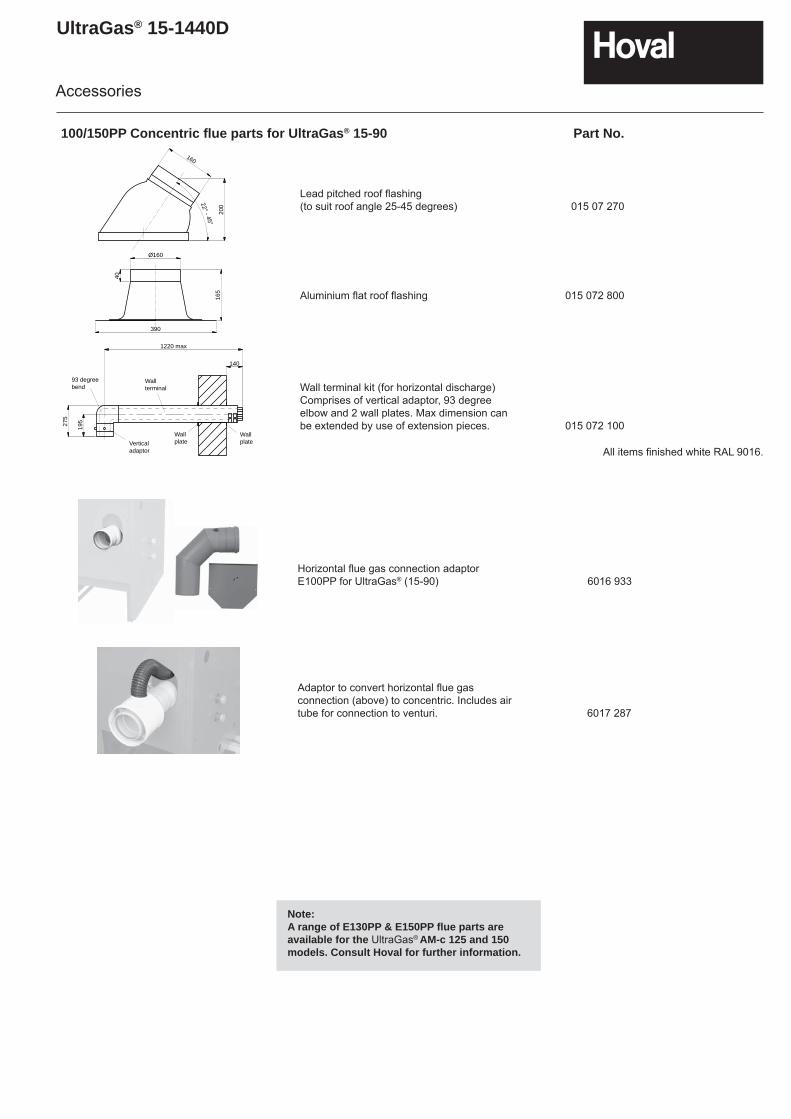
Lead pitched roof fl ashing(to suit roof angle 25-45 degrees) 015 07 270
Aluminium fl at roof fl ashing 015 072 800
Wall terminal kit (for horizontal discharge)Comprises of vertical adaptor, 93 degree elbow and 2 wall plates. Max dimension can be extended by use of extension pieces. 015 072 100
200
160
22° - 45°
390
40
Ø160
165
140
1220 max
19527
5
Wallplate
Wallplate
Wallterminal
93 degreebend
Verticaladaptor
Accessories
All items fi nished white RAL 9016.
Horizontal fl ue gas connection adaptorE100PP for UltraGas® (15-90) 6016 933
Adaptor to convert horizontal fl ue gas connection (above) to concentric. Includes air tube for connection to venturi. 6017 287
Note:A range of E130PP & E150PP fl ue parts are available for the UltraGas® AM-c 125 and 150 models. Consult Hoval for further information.
UltraGas® 15-1440D
Accessories for Heating regulator TopTronic®T Part No.
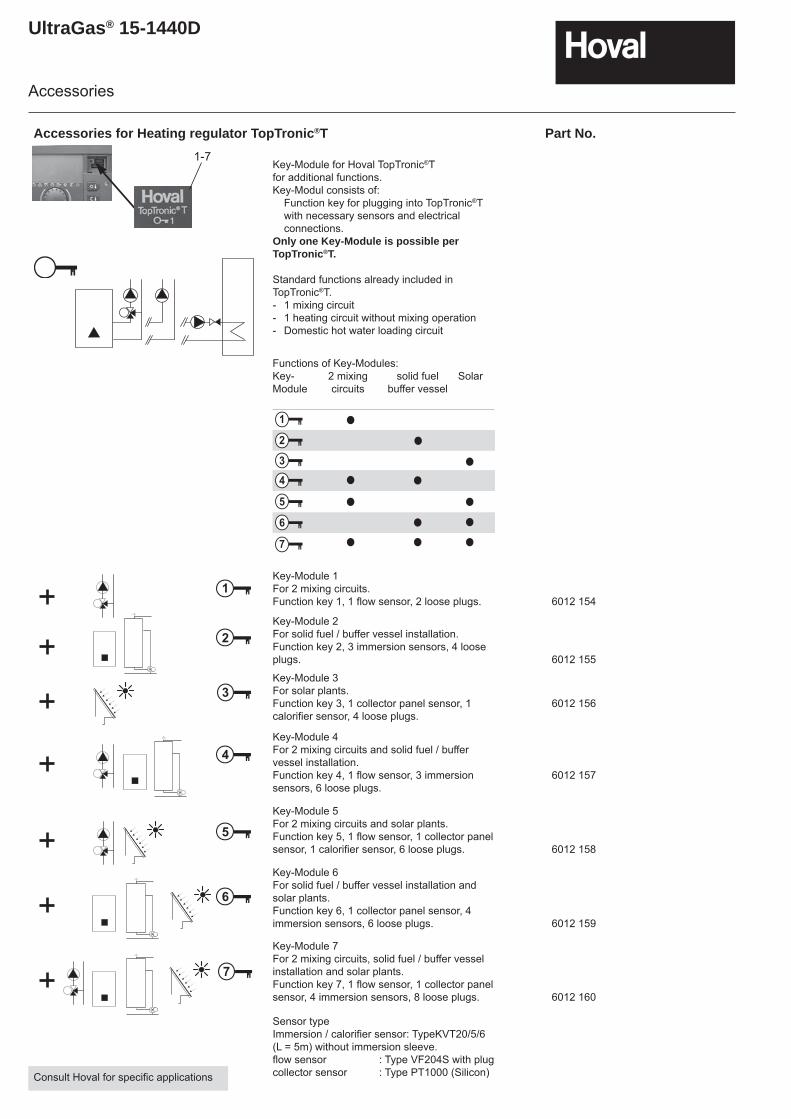
Key-Module for Hoval TopTronic®Tfor additional functions.Key-Modul consists of: Function key for plugging into TopTronic®T
with necessary sensors and electrical connections.
Only one Key-Module is possible per TopTronic®T.
Standard functions already included in TopTronic®T.- 1 mixing circuit- 1 heating circuit without mixing operation- Domestic hot water loading circuit
Key-Module 1For 2 mixing circuits.Function key 1, 1 flow sensor, 2 loose plugs. 6012 154
Key-Module 2For solid fuel / buffer vessel installation. Function key 2, 3 immersion sensors, 4 loose plugs. 6012 155
Key-Module 3For solar plants.Function key 3, 1 collector panel sensor, 1 calorifier sensor, 4 loose plugs.
6012 156
Key-Module 4For 2 mixing circuits and solid fuel / buffer vessel installation.Function key 4, 1 flow sensor, 3 immersion sensors, 6 loose plugs.
6012 157
Key-Module 5For 2 mixing circuits and solar plants.Function key 5, 1 flow sensor, 1 collector panel sensor, 1 calorifier sensor, 6 loose plugs. 6012 158
Key-Module 6For solid fuel / buffer vessel installation and solar plants.Function key 6, 1 collector panel sensor, 4 immersion sensors, 6 loose plugs. 6012 159
Key-Module 7For 2 mixing circuits, solid fuel / buffer vessel installation and solar plants.Function key 7, 1 flow sensor, 1 collector panel sensor, 4 immersion sensors, 8 loose plugs. 6012 160
Sensor typeImmersion / calorifier sensor: TypeKVT20/5/6 (L = 5m) without immersion sleeve.flow sensor : Type VF204S with plugcollector sensor : Type PT1000 (Silicon)
Accessories
Functions of Key-Modules:Key- 2 mixing solid fuel SolarModule circuits buffer vessel
2
1
4
5
6
7
3
M
1
2
3
4
5
6
7
1-7
M
M
M
M
M
M
M
Consult Hoval for specific applications
UltraGas® 15-1440D
Accessories
Accessories for Heating regulator TopTronic®T Part No.
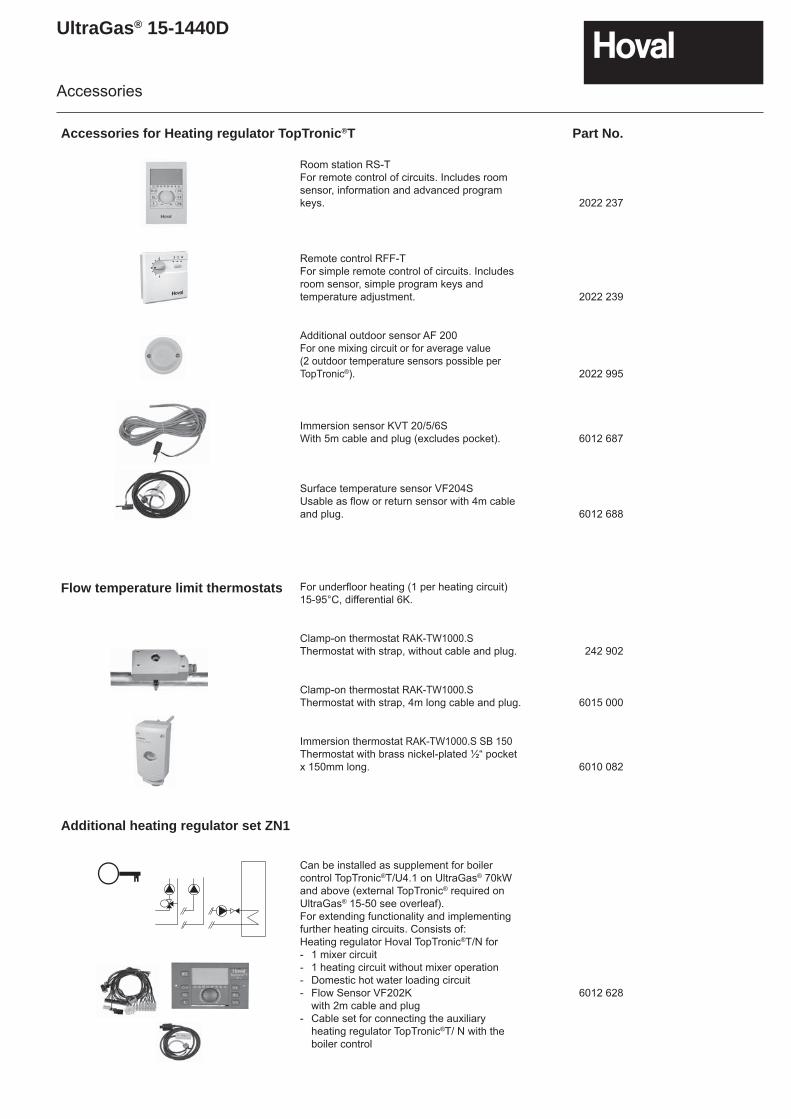
Room station RS-TFor remote control of circuits. Includes room sensor, information and advanced program keys. 2022 237
Remote control RFF-TFor simple remote control of circuits. Includes room sensor, simple program keys and temperature adjustment. 2022 239
Additional outdoor sensor AF 200For one mixing circuit or for average value (2 outdoor temperature sensors possible per TopTronic®). 2022 995
Immersion sensor KVT 20/5/6SWith 5m cable and plug (excludes pocket). 6012 687
Surface temperature sensor VF204SUsable as flow or return sensor with 4m cableand plug. 6012 688
Flow temperature limit thermostats For underfloor heating (1 per heating circuit) 15-95°C, differential 6K.
Clamp-on thermostat RAK-TW1000.SThermostat with strap, without cable and plug. 242 902
Clamp-on thermostat RAK-TW1000.SThermostat with strap, 4m long cable and plug. 6015 000
Immersion thermostat RAK-TW1000.S SB 150Thermostat with brass nickel-plated ½“ pocket x 150mm long. 6010 082
Additional heating regulator set ZN1
Can be installed as supplement for boiler control TopTronic®T/U4.1 on UltraGas® 70kW and above (external TopTronic® required on UltraGas® 15-50 see overleaf).For extending functionality and implementing further heating circuits. Consists of:Heating regulator Hoval TopTronic®T/N for - 1 mixer circuit- 1 heating circuit without mixer operation- Domestic hot water loading circuit- Flow Sensor VF202K with 2m cable and plug- Cable set for connecting the auxiliary
heating regulator TopTronic®T/ N with the boiler control
6012 628
UltraGas® 15-1440D
Accessories
External TopTronic®T Part No.
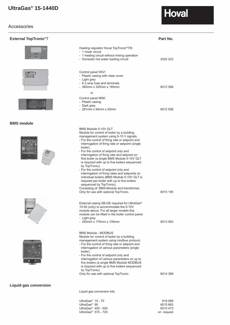
Heating regulator Hoval TopTronic®T/N- 1 mixer circuit- 1 heating circuit without mixing operation- Domestic hot water loading circuit 2022 223
Control panel WG1- Plastic casing with clear cover- Light grey- 6.3 amp fuse and terminals- 365mm x 320mm x 160mm 6012 598
or
Control panel MSK- Plastic casing- Dark grey- 281mm x 94mm x 93mm 6012 508
BMS moduleBMS Module 0-10V GLT Module for control of boiler by a building management system using 0-10 V signals.- For the control of firing rate or setpoint and interrogation of firing rate or setpoint (single boiler).- For the control of setpoint only and interrogation of firing rate and setpoint on first boiler (a single BMS Module 0-10V GLT is required with up to five boilers sequenced by TopTronic).- For the control of setpoint only and interrogation of firing rates and setpoints on individual boilers (BMS Module 0-10V GLT is required per boiler with up to five boilers sequenced by TopTronic).Consisting of: BMS-Module and transformer.Only for use with optional TopTronic. 6015 195
External casing SB-GE required for UltraGas® 15-50 (only) to accommodate the 0-10V module above. For all larger models this module can be fitted in the boiler control panel.- Light grey- 250mm x 175mm x 100mm 6013 063
BMS Module - MODBUS Module for control of boiler by a building management system using modbus protocol.- For the control of firing rate or setpoint and interrogation of various parameters (single boiler).- For the control of setpoint only and interrogation of various parameters on up to five boilers (a single BMS Module MODBUS is required with up to five boilers sequenced by TopTronic).Only for use with optional TopTronic. 6014 389
Liquid gas conversionLiquid gas conversion kits
UltraGas® 15 - 70UltraGas® 90UltraGas® 400 - 500UltraGas® 575 - 720
619 5686015 6636015 473
on request
UltraGas® 15-1440D
Accessories
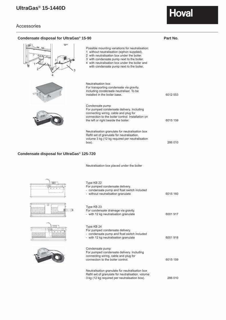
Condensate disposal for UltraGas® 15-90 Part No.
Possible mounting variations for neutralisation:1 without neutralisation (siphon supplied).2 with neutralisation box under the boiler.3 with condensate pump next to the boiler.4 with neutralisation box under the boiler and
with condensate pump next to the boiler.
Neutralisation boxFor transporting condensate via gravity. Including condensate neutraliser. To be installed in the boiler base. 6012 553
Condensate pumpFor pumped condensate delivery. Including connecting wiring, cable and plug for connection to the boiler control. Installation on the left or right beside the boiler. 6015 159
Neutralisation granulate for neutralisation boxRefill set of granulate for neutralisation, volume 3 kg (12 kg required per neutralisation box). 286 010
Condensate disposal for UltraGas® 125-720
Neutralisation box placed under the boiler
Type KB 22For pumped condensate delivery.- condensate pump and float switch included- without neutralisation granulate 6015 160
Type KB 23For condensate drainage via gravity.- with 12 kg neutralisation granulate 6001 917
Type KB 24For pumped condensate delivery.- condensate pump and float switch included- with 12 kg neutralisation granulate 6001 918
Condensate pumpFor pumped condensate delivery. Including connecting wiring, cable and plug for connection to the boiler control. 6015 159
Neutralisation granulate for neutralisation boxRefill set of granulate for neutralisation, volume 3 kg (12 kg required per neutralisation box). 286 010
1
2
43
UltraGas® 15-1440D
Accessories
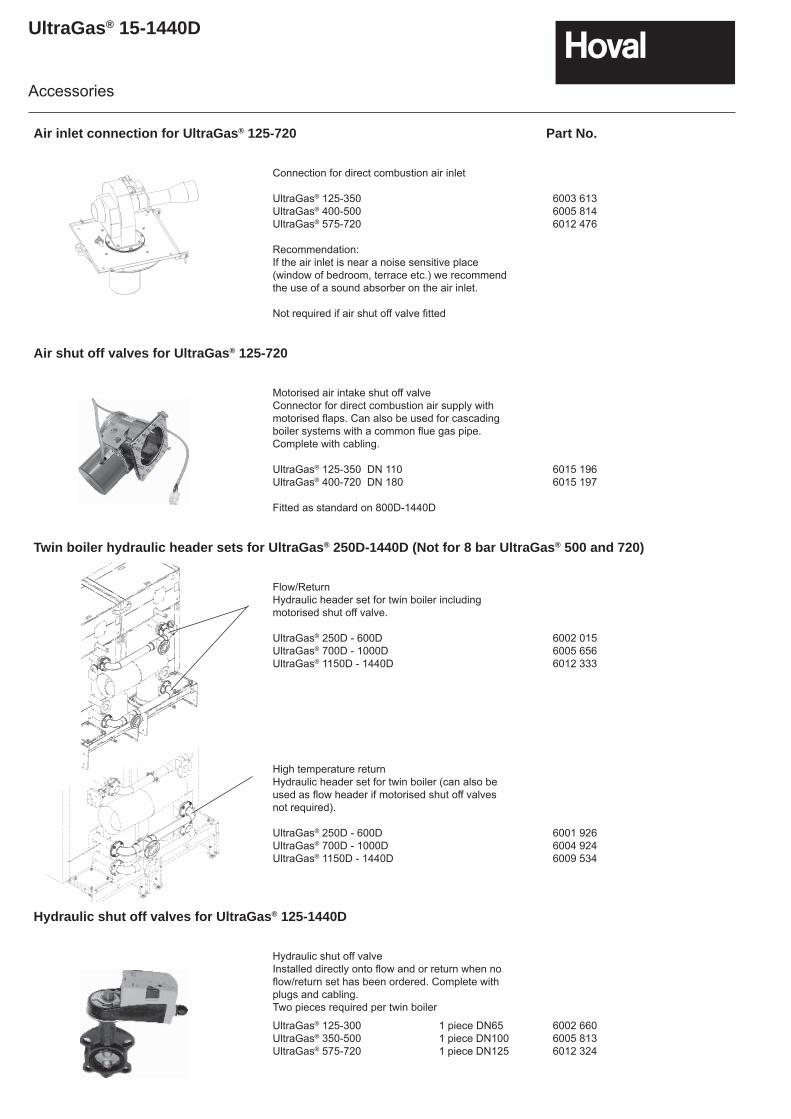
Air inlet connection for UltraGas® 125-720 Part No.
Connection for direct combustion air inlet
UltraGas® 125-350UltraGas® 400-500UltraGas® 575-720
Recommendation:If the air inlet is near a noise sensitive place (window of bedroom, terrace etc.) we recommend the use of a sound absorber on the air inlet.
Not required if air shut off valve fi tted
6003 6136005 8146012 476
Air shut off valves for UltraGas® 125-720
Motorised air intake shut off valveConnector for direct combustion air supply with motorised flaps. Can also be used for cascading boiler systems with a common flue gas pipe. Complete with cabling.
UltraGas® 125-350 DN 110UltraGas® 400-720 DN 180
Fitted as standard on 800D-1440D
6015 1966015 197
Twin boiler hydraulic header sets for UltraGas® 250D-1440D (Not for 8 bar UltraGas® 500 and 720)
Flow/ReturnHydraulic header set for twin boiler including motorised shut off valve.
UltraGas® 250D - 600DUltraGas® 700D - 1000DUltraGas® 1150D - 1440D
6002 0156005 6566012 333
High temperature returnHydraulic header set for twin boiler (can also be used as fl ow header if motorised shut off valves not required).
UltraGas® 250D - 600DUltraGas® 700D - 1000DUltraGas® 1150D - 1440D
6001 9266004 9246009 534
Hydraulic shut off valves for UltraGas® 125-1440D
Hydraulic shut off valveInstalled directly onto flow and or return when no flow/return set has been ordered. Complete with plugs and cabling.Two pieces required per twin boiler
UltraGas® 125-300 1 piece DN65UltraGas® 350-500 1 piece DN100UltraGas® 575-720 1 piece DN125
6002 6606005 8136012 324

UltraGas® 15-1440D
Accessories
Boiler-Connection set for UltraGas® 15-90 Part No.
For the installation of a heating circuit set on the Hoval UltraGas® 15-90.Suitable for left hand or right hand installation.Rigid flow pipe and flexible return. Fully insulated and complete with fittings
AS25-S/NT/ HT low or high temperature returnSuitable for set HA25 on UltraGas® 15-27.
AS32-S/NT/ HT low or high temperature returnSuitable for set HA32 on UltraGas® 35-50.
AS40-S/NT/ HT low or high temperature returnSuitable for set HA40 on UltraGas® 70-90. (for heating circuit set HA32 adaptor set DN32-40 needed)
6017 055
6014 846
6014 848
Adaptor set DN32-DN40 6014 863
Heating circuit set type HA-2 (Right hand side is only available).Complete with thermally insulated box.
HCS type pump type
DN25(1") HA25-2/MX12-1 MX12-1/230 V HA25-2/MX13-1 MX13-1/230 V HA25-2/MXE12-1 MXE12-1/230 VDN32(1¼") HA32-2/MX13-2 MX13-2/230 VDN40(1½") HA40-2/LX403 HXE403/230 V HA40-2/LX403 HXE403/400 V HA40-2/HX402-1 HX402-1/400 V
6012 7196012 7216012 7236012 7306015 7056015 7066015 707
Heating circuit set type HA-3BM-R (Right hand side version)Complete with three-way mixing valve and thermally insulated box.
HCS type pump type
DN25(1") HA25-3BM-R/MX12-1 MX12-1/230 V HA25-3BM-R/MX13-1 MX13-1/230 V HA25-3BM-R/MXE12-1 MXE12-1/230 V HA25-3BM-R/MXE13-1 MXE13-1/230 VDN32(1¼") HA32-3BM-R/MX13-2 MX13-2/230 V HA32-3BM-R/M14-2 M14-2/230 V HA32-3BM-R/MXE13-2 MXE13-2/230 VDN40(1½") HA40-3M-R/LX403 HXE403/230 V HA40-3M-R/LX403 HXE403/400 V HA40-3M-R/HX402-1 HX402-1/400 V HA40-3M-R/HXE402-1 HXE402-1/230 V HA40-3M-R/HXP402-1 HXP402-1/230 V
6012 7046012 7056012 7066012 7076012 7246012 7256012 7266015 6936015 6946015 6956015 6966016 697
Heating circuit set type HA-3BM-L (Left hand side version)Complete with three-way mixing valve and thermally insulated box.
HCS type pump type
DN25(1") HA25-3BM-L/MX12-1 MX12-1/230 V HA25-3BM-L/MX13-1 MX13-1/230 V HA25-3BM-L/MXE12-1 MXE12-1/230 V HA25-3BM-L/MXE13-1 MXE13-1/230 VDN32(1¼") HA32-3BM-L/MX13-2 MX13-2/230 V HA32-3BM-L/M14-2 M14-2/230 V HA32-3BM-L/MXE13-2 MXE13-2/230 V
6012 7116012 7126012 7136012 7146012 7276012 7286012 729
Circuit set type LG-2 for free standing CombiVal calorifier.Complete with thermally insulated box.
HCS type pump type
DN25(1") LG25-2/MX12-1 MX12-1/230 V LG25-2/MX13-1 MX13-1/230 VDN32(1¼") LG32-2/MX13-2 MX13-2/230 V
6012 7206012 7226012 731
UltraGas® 15-1440D
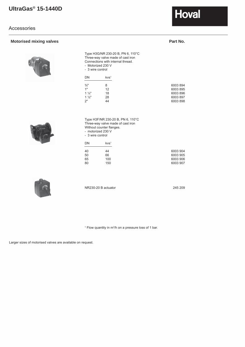
Motorised mixing valves Part No.
Type H3G/NR 230-20 B, PN 6, 110°C Three-way valve made of cast ironConnections with internal thread.- Motorized 230 V- 3 wire control
DN kvs1
¾" 8 1" 12 1 ¼" 18 1 ½" 28 2" 44
6003 8946003 8956003 8966003 8976003 898
Type H3F/NR 230-20 B, PN 6, 110°CThree-way valve made of cast ironWithout counter fl anges.- motorized 230 V- 3 wire control
DN kvs1
40 44 50 66 65 100 80 150
6003 9046003 9056003 9066003 907
NR230-20 B actuator 245 209
1 Flow quantity in m3/h on a pressure loss of 1 bar.
Larger sizes of motorised valves are available on request.
Accessories
UltraGas® 15-1440D
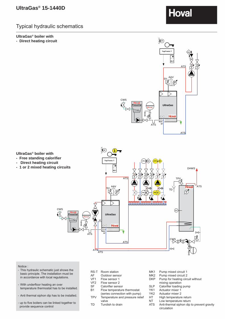
UltraGas® boiler with - Direct heating circuit
UltraGas® boiler with - Free standing calorifier- Direct heating circuit- 1 or 2 mixed heating circuits
RS-T Room stationAF Outdoor sensorVF1 Flow sensor 1VF2 Flow sensor 2SF Calorifier sensorB1 Flow temperature thermostat (series connection with pump)TPV Temperature and pressure relief
valveTD Tundish to drain
MK1 Pump mixed circuit 1MK2 Pump mixed circuit 2DKP Pump for heating circuit without mixing operationSLP Calorifier loading pumpYK1 Actuator mixer 1YK2 Actuator mixer 2HT High temperature returnNT Low temperature returnATS Anti-thermal siphon dip to prevent gravity
circulation
Typical hydraulic schematics
Notice :- This hydraulic schematic just shows the basic principle. The installation must be in accordance with local regulations.
- With underfloor heating an over temperature thermostat has to be installed.
- Anti thermal siphon dip has to be installed.
- up to five boilers can be linked together to provide sequence control
D i e s i s t e i nunerlaubter Weg!Gehe n Sie e inenSchritt zurück oderlöschen Sie diesesShape!S i e h a b e n d i eM ö g l i c h k e i t e i nn e ue s S ha p e zun e h m e n ! ! !hovhovalhhovalhovaalhovalho
P
UltraGas
NT
TT
D K P
B 1
RS-T
AF
TopTronic T
Hoval
HovalPressVal
CWS
ATS
ATS
ATS
AAVSV
D i e s i s t e i nunerlaubter Weg!Gehe n Sie eine nSchritt zurück oderlöschen Sie diesesShape!S i e h a b e n d i eM ö g l i c h k e i t e i nn e ues S ha pe z un e h m e n ! ! !hovhovalhhovalhovaalhovalho
P
UltraGas
NT
RS-T
AF
TopTronic T
1
TT
D K P
TT
M K 1
MYK1
B1VF1
TT
D K P
B1VF2
TT
M K 2
MYK2
B1VF2
TT
M K 2
MYK2
S L P
HT
DHWS
D i e s i s t e i nu n e r l a u b t e rWeg!G e h e n S i eei ne n Sc hr i t tz u r ü c k o d e rl ö s c h e n S i edieses Shape!Sie haben dieMöglichkeit einneues Shape zun e h m e n ! ! !hovhovalhovalhovalhovalhovalhovalhovalhovalhovalhovalhovalhovalhovalhovalhovalhovalhovalhovalhovalhovalhovalhovalhovalhovalhovalhovalhovalhovalhovalhovalh
T
S F
TPV
TD
Hoval
HovalPressVal
CWS
ATS
ATS
ATS
ATS
ATSATS
AAVSV
CWS
UltraGas® 15-1440D
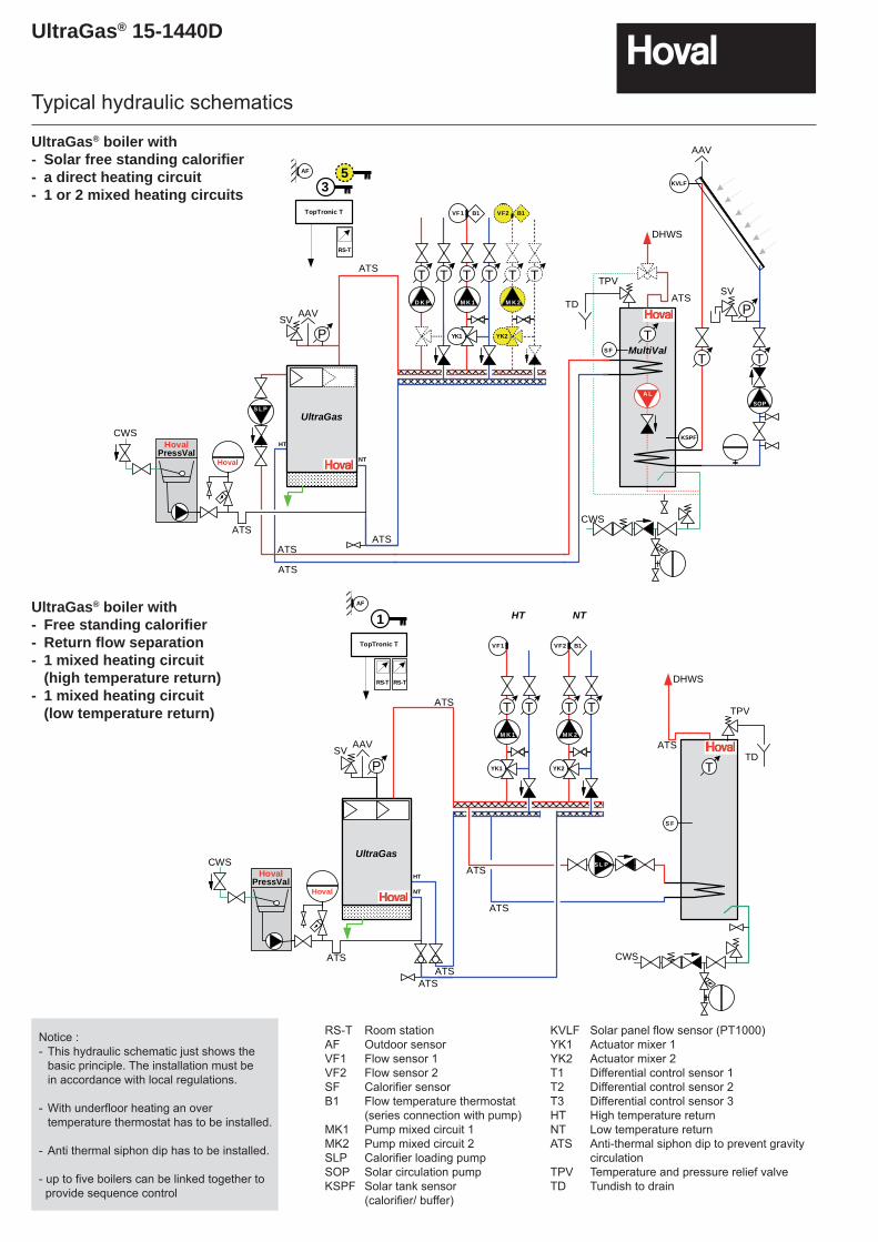
UltraGas® boiler with - Solar free standing calorifier- a direct heating circuit- 1 or 2 mixed heating circuits
UltraGas® boiler with - Free standing calorifier- Return flow separation- 1 mixed heating circuit
(high temperature return)- 1 mixed heating circuit
(low temperature return)
RS-T Room stationAF Outdoor sensor VF1 Flow sensor 1VF2 Flow sensor 2SF Calorifier sensorB1 Flow temperature thermostat (series connection with pump)MK1 Pump mixed circuit 1MK2 Pump mixed circuit 2SLP Calorifier loading pumpSOP Solar circulation pumpKSPF Solar tank sensor
(calorifier/ buffer)
KVLF Solar panel flow sensor (PT1000)YK1 Actuator mixer 1YK2 Actuator mixer 2T1 Differential control sensor 1T2 Differential control sensor 2T3 Differential control sensor 3HT High temperature returnNT Low temperature returnATS Anti-thermal siphon dip to prevent gravity
circulationTPV Temperature and pressure relief valve TD Tundish to drain
Typical hydraulic schematics
Notice :- This hydraulic schematic just shows the basic principle. The installation must be in accordance with local regulations.
- With underfloor heating an over temperature thermostat has to be installed.
- Anti thermal siphon dip has to be installed.
- up to five boilers can be linked together to provide sequence control
RS-T
AF
TopTronic T
3
S L P
D i e s i s t e i nunerlaubter Weg!Gehen Sie e ine nSchritt zurück oderlöschen Sie diesesShape!S i e h a b e n d i eM ö g l i c hk e i t e i nne u es Sh ape z un e h m e n ! ! !hovhovalhhovalhovaalhovalho
UltraGas
P
NT
HT
NT
HT
TT
D K P
TT
M K 1
MYK1
B1VF1
TT
D K P
B1VF2
TT
M K 2
MYK2
B1VF2
TT
M K 2
MYK2
5
DHWS
D i e s i s t e i nu n e r l a u b t e rWeg!G e h e n S i ee ine n Sc hr i t tz u r ü c k o d e rl ö s c h e n S i edieses Shape!Sie haben dieMöglichkeit einneues Shape zun e h m e n ! ! !hovhovalhovalhovalhovalhovalhovalhovalhovalhovalhovalhovalhovalhovalhovalhovalhovalhovalhovalhovalhovalhovalhovalhovalhovalhovalhovalhovalhovalhovalhovalh
TS F
KSPFT 2SLVFKSPF
TT
SOP
P
KVLFS 1KVLF
TPV
TD
Hoval
HovalPressVal
CWS
ATS
ATS
ATS
ATS
ATS
ATS
AAVSV
AAV
SV
CWS
A L
MultiVal
D i e s i s t e i nunerlaubter Weg!Gehen Sie e ine nSchritt zurück oderlöschen Sie diesesShape!S i e h a b e n d i eM ö g l i c hk e i t e i nne u es Sh ape z un e h m e n ! ! !hovhovalhhovalhovaalhovalho
UltraGas
NT
HT
NT
HT
PD i e s i s t e i nu n e r l a u b t e rWeg!G e h e n S i ee ine n S chr i ttz u r ü c k o d e rl ö s c h e n S i edieses Shape!Sie haben dieMöglichkeit einneues Shape zun e h m e n ! ! !hovhovalhovalhovalhovalhovalhovalhovalhovalhovalhovalhovalhovalhovalhovalhovalhovalhovalhovalhovalhovalhovalhovalhovalhovalhovalhovalhovalhovalhovalhovalh
DHWS
T
S F
S L P
RS-T
AF
TopTronic T
RS-T
1 HT NT
B1VF2
TT
M K 2
MYK2
B1VF2
TT
M K 2
MYK2
VF1
TT
M K 1
MYK1
TPV
TD
Hoval
HovalPressVal
CWS
ATS
ATS
ATS
ATS
ATS
ATSATS
AAVSV
CWS
UltraGas® 15-1440D
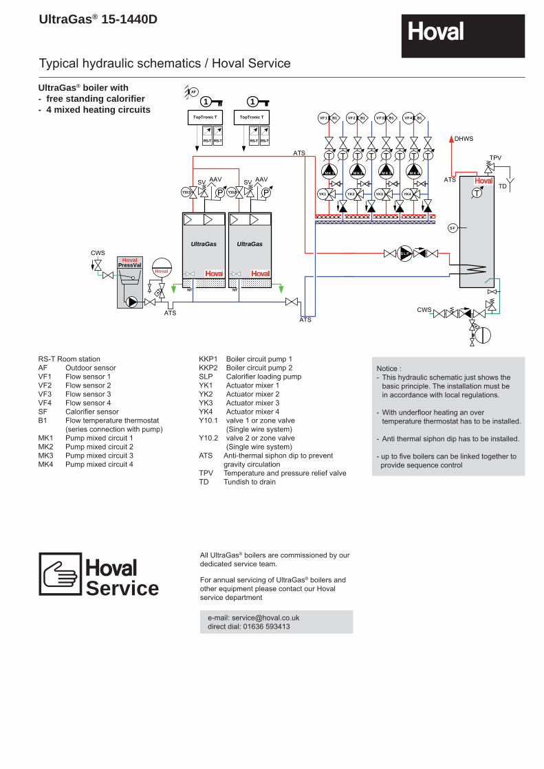
UltraGas® boiler with - free standing calorifier- 4 mixed heating circuits
RS-T Room stationAF Outdoor sensorVF1 Flow sensor 1VF2 Flow sensor 2VF3 Flow sensor 3VF4 Flow sensor 4SF Calorifi er sensorB1 Flow temperature thermostat (series connection with pump)MK1 Pump mixed circuit 1MK2 Pump mixed circuit 2MK3 Pump mixed circuit 3MK4 Pump mixed circuit 4
KKP1 Boiler circuit pump 1KKP2 Boiler circuit pump 2SLP Calorifi er loading pumpYK1 Actuator mixer 1YK2 Actuator mixer 2YK3 Actuator mixer 3YK4 Actuator mixer 4Y10.1 valve 1 or zone valve
(Single wire system)Y10.2 valve 2 or zone valve
(Single wire system)ATS Anti-thermal siphon dip to prevent
gravity circulationTPV Temperature and pressure relief valveTD Tundish to drain
All UltraGas® boilers are commissioned by our dedicated service team.
For annual servicing of UltraGas® boilers and other equipment please contact our Hoval service department
e-mail: [email protected] dial: 01636 593413
Typical hydraulic schematics / Hoval Service
Service
Notice :- This hydraulic schematic just shows the basic principle. The installation must be in accordance with local regulations.
- With underfloor heating an over temperature thermostat has to be installed.
- Anti thermal siphon dip has to be installed.
- up to five boilers can be linked together to provide sequence control
D i e s i s t e i nunerlaubter Weg!Gehe n Sie eine nSchritt zurück oderlöschen Sie diesesShape!S i e h a b e n d i eM ö g l i c h k e i t e i nn e ue s S ha pe z un e h m e n ! ! !hovhovalhhovalhovaalhovalho
D i e s i s t e i nunerlaubter Weg!Ge hen Sie ei ne nSchritt zurück oderlöschen Sie diesesShape!S i e h a b e n d i eM ö g l i c h k e i t e i nne u e s Sh a pe z un e h m e n ! ! !hovhovalhhovalhovaalhovalho
Y10.2 PPY10.1
UltraGasUltraGas
B1VF3
TT
M K 3
MYK3
B1VF3
TT
M K 3
MYK3
B1VF2
TT
M K 2
MYK2
B1VF2
TT
M K 2
MYK2
B1VF1
TT
M K 1
MYK1D i e s i s t e i nu n e r l a u b t e rWeg!G e h e n S i ee ine n Sc hr i t tz u r ü c k o d e rl ö s c h e n S i edieses Shape!Sie haben dieMöglichkeit einneues Shape zun e h m e n ! ! !hovhovalhovalhovalhovalhovalhovalhovalhovalhovalhovalhovalhovalhovalhovalhovalhovalhovalhovalhovalhovalhovalhovalhovalhovalhovalhovalhovalhovalhovalhovalh
DHWS
T
S F
S L P
B1VF4
TT
M K 4
MYK4
B1VF4
TT
M K 4
MYK4
RS-T
AF
TopTronic T
RS-T
1
RS-T
TopTronic T
RS-T
1
TPV
TD
Hoval
HovalPressVal
CWS
ATSATS
ATS
ATSAAVSV AAVSV
NT NT
CWS
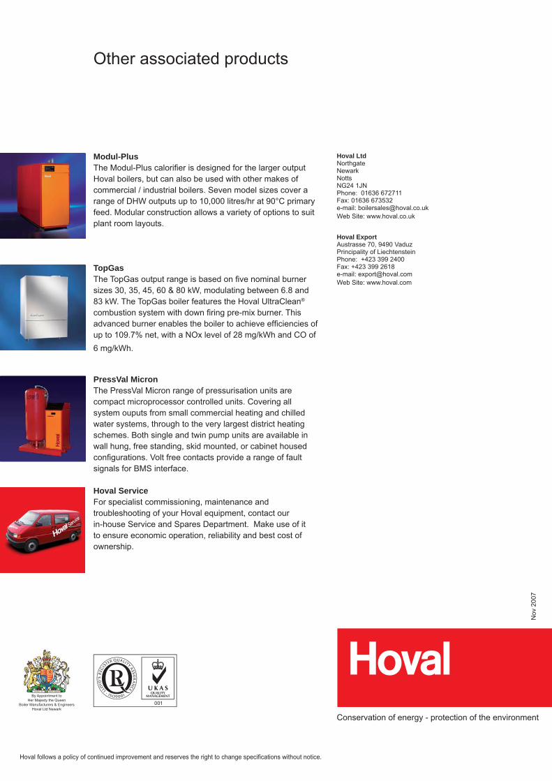
Other associated products
Modul-PlusThe Modul-Plus calorifi er is designed for the larger output Hoval boilers, but can also be used with other makes of commercial / industrial boilers. Seven model sizes cover a range of DHW outputs up to 10,000 litres/hr at 90°C primary feed. Modular construction allows a variety of options to suit plant room layouts.
TopGasThe TopGas output range is based on fi ve nominal burner sizes 30, 35, 45, 60 & 80 kW, modulating between 6.8 and 83 kW. The TopGas boiler features the Hoval UltraClean® combustion system with down fi ring pre-mix burner. This advanced burner enables the boiler to achieve effi ciencies of up to 109.7% net, with a NOx level of 28 mg/kWh and CO of 6 mg/kWh.
PressVal MicronThe PressVal Micron range of pressurisation units are compact microprocessor controlled units. Covering all system ouputs from small commercial heating and chilled water systems, through to the very largest district heating schemes. Both single and twin pump units are available in wall hung, free standing, skid mounted, or cabinet housed configurations. Volt free contacts provide a range of fault signals for BMS interface.
Hoval ServiceFor specialist commissioning, maintenance and troubleshooting of your Hoval equipment, contact ourin-house Service and Spares Department. Make use of it to ensure economic operation, reliability and best cost of ownership.
Hoval Ltd Northgate Newark Notts NG24 1JNPhone: 01636 672711Fax: 01636 673532e-mail: [email protected] Site: www.hoval.co.uk
Hoval Export Austrasse 70, 9490 VaduzPrincipality of Liechtenstein Phone: +423 399 2400Fax: +423 399 2618e-mail: [email protected] Site: www.hoval.com
Hoval follows a policy of continued improvement and reserves the right to change specifi cations without notice.
Nov
200
7
Conservation of energy - protection of the environment
By Appointment toHer Majesty the Queen
Boiler Manufacturers & EngineersHoval Ltd Newark


