28
HYDRAULIC MAINTENANCE & SAFETY Tips to prevent downtime and save you money. Presented by Gates Corporation
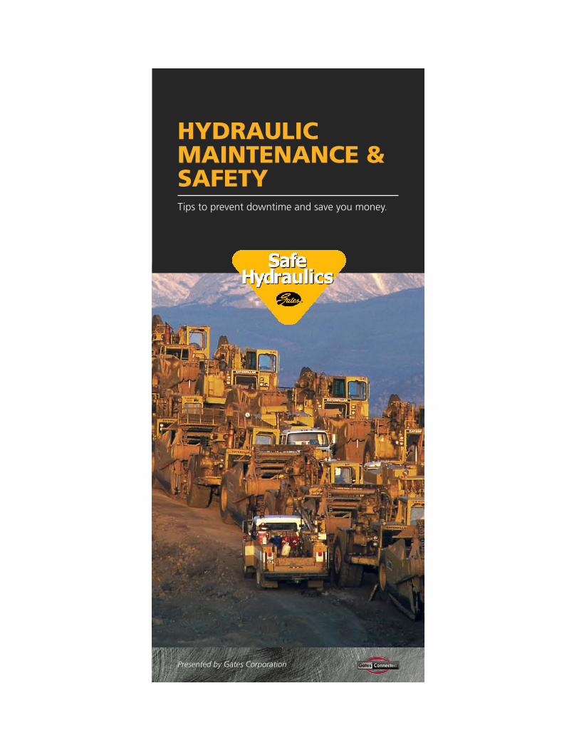
HYDRAULIC MAINTENANCE &SAFETYTips to prevent downtime and save you money.
Presented by Gates Corporation

TABLE OF CONTENTS
WHY PREVENTIVE MAINTENANCE? . . . . . . . . . . . . . . . .1
CHOOSING THE RIGHT COMPONENTS . . . . . . . . . . . . . .2
AGENCY SPECIFICATIONS . . . . . . . . . . . . . . . . . . . . . . . .6
COUPLING IDENTIFICATION . . . . . . . . . . . . . . . . . . . . . . .8
HOSE ROUTING . . . . . . . . . . . . . . . . . . . . . . . . . . . . . . . . .13
HOSE CLEANLINESS . . . . . . . . . . . . . . . . . . . . . . . . . . . .16
ASSEMBLY INSTALLATION . . . . . . . . . . . . . . . . . . . . . . .17
PERIODIC INSPECTIONS . . . . . . . . . . . . . . . . . . . . . . . . .21
HOSE TROUBLESHOOTING . . . . . . . . . . . . . . . . . . . . . . .22
SAFE HYDRAULICS . . . . . . . . . . . . . . . . . . . . . . . . . . . . .25

WHY PREVENTIVE MAINTENANCE?
Hydraulic preventive maintenance and safety is important foranyone who operates hydraulically powered equipment. Improperlymaintained assemblies can cause premature hose failure andblowouts, resulting in equipment downtime, possible equipmentdamage, personal injury and even death.
At Gates, we believe following proper preventive maintenanceprocedures is time well spent. Shown below are some of thenumerous benefits provided by preventive maintenance.
Let’s take a look at some preventive maintenance and safetyprocedures. They’ll put you on the right track to safe and long-lasting hydraulic assemblies.
BENEFITS• Reduce downtime• Improve production• Increase efficiency of
maintenance personnel• Enhance control of spare
parts inventory• Decrease safety hazards
and accidents• Extend equipment
service life• Reduce capital outlays
for new equipment
1
CHOOSING THE RIGHT COMPONENTS
2
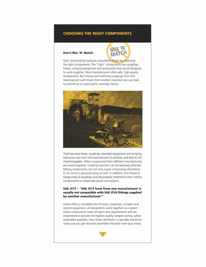
MIX ‘N’
MATCHDon't Mix ‘N’ Match
Safe, long-lasting hydraulic assemblies begin by choosingthe right components. The “right” components are couplings,hoses, crimping equipment and accessories that are all designedto work together. Most manufacturers offer safe, high-qualitycomponents. But mixing and matching couplings from onemanufacturer with hoses from another manufacturer can lead to premature or catastrophic assembly failure.
That’s because hoses, couplings, assembly equipment and crimpingtolerances vary from one manufacturer to another, and they’re notinterchangeable. When components from different manufacturersare mixed together, coupling retention can be adversely affected.Mixing components can not only cause unnecessary downtime,it can result in personal injury as well. In addition, the thread orflange ends of couplings must be properly matched to their matingcomponents to create leak-proof connections.
SAE J517 – “SAE J517 hose from one manufacturer isusually not compatible with SAE J516 fittings suppliedby another manufacturer.”
Gates offers a complete line of hoses, couplings, crimpers andrelated equipment, all designed to work together as a system.Gates components meet stringent test requirements and are engineered to provide the highest quality, longest lasting, safestassemblies available. Your Gates distributor is specially trained tomake sure you get the hose assemblies that best meet your needs.
The Critical Design Factor
Hydraulic system performance is determined by the weakestcomponent, which is often the hose/coupling interface. Controllinghow the coupling is connected to the hose and their interactionis critical to designing effective, reliable and safe hydraulichose assemblies.
Choosing the Right Hose
Choosing the right hose is the first step to long and safe assemblyservice life. But before we look into how to select the proper hosefor the job, let’s first take a look at the benefits of using rubberhose in fluid power applications. Unlike rigid tubing, rubber hoseoffers several advantages:
• Less susceptible to vibration and movement• Requires no brazing or specialized bending• Easier to obtain in the aftermarket• Faster to route around obstacles• Absorbs sound and impulses• Dampens pressure surges
Given its superior availability and routing advantages, rubber hoseis preferred over metal tubing by most maintenance personnel.In fact, it’s not uncommon for maintenance technicians to replacemetal tubing with a hose assembly.
Hose Construction
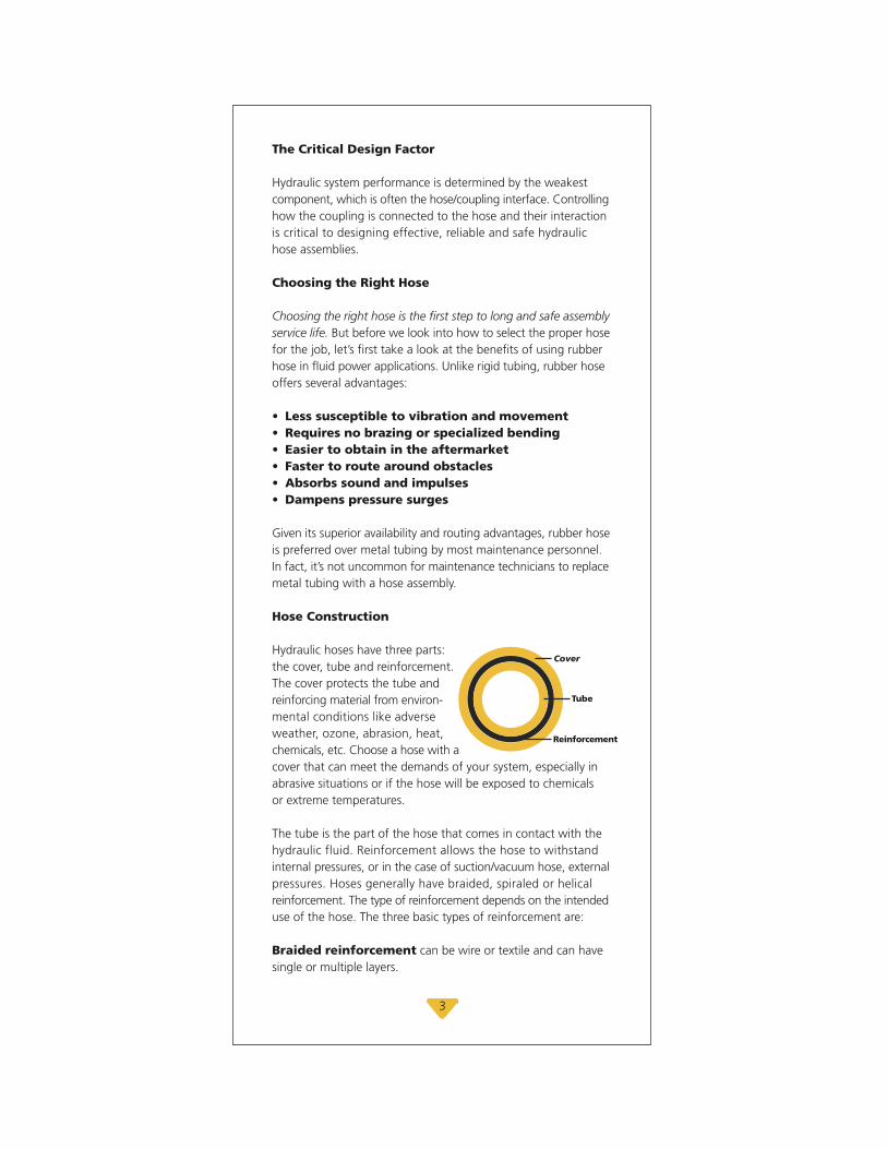
Hydraulic hoses have three parts: the cover, tube and reinforcement.The cover protects the tube and reinforcing material from environ-mental conditions like adverseweather, ozone, abrasion, heat,chemicals, etc. Choose a hose with acover that can meet the demands of your system, especially inabrasive situations or if the hose will be exposed to chemicals or extreme temperatures.
The tube is the part of the hose that comes in contact with thehydraulic fluid. Reinforcement allows the hose to withstandinternal pressures, or in the case of suction/vacuum hose, externalpressures. Hoses generally have braided, spiraled or helicalreinforcement. The type of reinforcement depends on the intendeduse of the hose. The three basic types of reinforcement are:
Braided reinforcement can be wire or textile and can havesingle or multiple layers.
Cover
Reinforcement
Tube
3

Spiraled reinforcement on hydraulic hose is typically wireor textile and has four or six layers (plies). Spiral-reinforced hosecan typically handle more severe applications with longer impulseservice life.
Helical coil reinforcement keeps the hose from collapsingduring suction (vacuum) and tight bending.
When choosing a hose, it’s crucial that the cover, tube andreinforcement are all compatible with the type of fluid conveyedin the system. This is an important point to remember, becausemany hoses are not compatible with all of the hydraulic fluidson the market today, including petroleum-based, phosphate esters, water-based and diester fluids.
Other variables, such as elevated temperatures, fluid contaminationand fluid concentration, will also affect compatibility. When indoubt, consult the hose manufacturer.
The “STAMPED” Method
Studies by fluid power manufacturersindicate that the three most commoncauses of hydraulic hose failure areabuse, misapplication and improperplumbing. Equipment operators andtechnicians can reduce, if not eliminate,premature hydraulic hose failure bygiving maximum consideration to hoseassembly selection and installation.
Yet, with all of the different types of hoses on the market, choosing the right one can be difficult.
Gates suggests using the “STAMPED”method to ensure you get the righthose assembly for the job. “STAMPED”stands for Size, Temperature, Application,Material to be conveyed, Pressure,Ends or couplings, and Delivery. Here’s how it works:
Size – Choose a hose with an inside diameter that is adequateto minimize pressure loss and to avoid hose damage caused bythe heat generated by excessive fluid turbulence.
Temperature – The hose must be able to withstand the system’sminimum and maximum fluid and ambient temperatures.
SIZE
T
TEMPERATURE
A
APPLICATION
M
MATERIAL
P
PRESSURE
E
ENDS/COUPLINGS
D
DELIVERY
S
T
A
M
P
E
D
4

Application – Determine where or how the hose will be used.You’ll need to know the equipment type, working and impulsepressures, fluid to be used, bend radius, static conductivity, etc.
Material to be conveyed – The hose, including the hosetube and cover, along with the couplings and O-rings, must becompatible with the type of fluid being conveyed.
Pressure – Know the system pressure, including pressure spikes.The hose’s published working pressure must be equal to, orgreater than, the normal system pressure and any pressure surgesit will encounter.
Ends or Couplings – Identify the type of threads the system usesand select couplings that are compatible with those thread types.
Delivery – How many hose assemblies do you need and whendo you need them? Your local Gates distributor will work withyou to make sure you get the assemblies you need just in time.
5
Hose Size (Dash Numbers)Hose I.D. (inches)
All except C5 Series, C5 Series, C14 andC14 and AC134a AC134a
Dash Size Inches Millimeters Inches Millimeters
-2 1/8 3.2 — —-3 3/16 4.8 — —-4 1/4 6.4 3/16 4.8-5 5/16 7.9 1/4 6.4-6 3/8 9.5 5/16 7.9-8 1/2 12.7 13/32 10.3-10 5/8 15.9 1/2 12.7-12 3/4 19.0 5/8 15.9-14 7/8 22.2 — —-16 1 25.4 7/8 22.2-20 1 1/4 31.8 1 1/8 28.6-24 1 1/2 38.1 1 3/8 34.9-32 2 50.8 1 13/16 46.0-36 2 1/4 57.6 — —-40 2 1/2 63.5 2 3/8 60.3-48 3 76.2 — —-56 3 1/2 88.9 — —-64 4 101.6 — —-72 4 1/2 115.2 — —

6
AGENCY SPECIFICATIONS
Industry AgenciesABS – American Bureau of ShippingAS – Australia StandardDIN – Deutsch Industry Norm, GermanDNV – Det Norske Veritas for NorthSea Floating Vessels
EN – European Norm/StandardGL – Germanischer LloydsIJS – Industrial Jack SpecificationsRCCC – Regular Common Carrier Conference for Fleet Truck and BusSAE – Society of Automotive Engineers
Hose Type ABS AS DIN DNV EN GL IJS
EFG6K,G6K X X 20023 4SH/4SP X EN 856 4SH/4SPEFG5K,G5K X X 20023 4SH/4SP X EN 856 4SH/4SPEFG4K,G4K X X 20023 4SP EN 856 4SPEFG3K,G3K X 20023 4SP EN 856 4SPC12M X X 20023 4SP X EN 856 4SPC12 X 20023 4SP EN 856 4SPM5K X XM4K+ X X XM4KH X XG2XHG2AT-HMPM2T® X X XCM2T EN 853 2CSG2 X 20022 2SN X EN 853 2SN XG2H X X EN 853 2SNJ2AT XM3K X X X EN 857 XM3K -12, -16 X X X EN 857 XG1 X 20022 1SN X EN 853 1SN XG1H X EN 853 1SNMegaTech™TR500NABTC5CC5EC5DC5M XG3H EN 854 R3GTH EN 854 R6GMV X@ XLOLThermoplasticGT8, GT8NCGT7, GT7NC**C14RefrigerantPolarSeal®
AC134aPower SteeringPS188
* Except 1/4"** GT7NC meets ANSI A92.2 for vehicle mounted aerial devices (-3 to -8)

7
Government AgenciesDOT/FMVSS – U.S. Department ofTransportation/Federal Motor VehicleSafety Standard
MSHA – U.S. Mine Safety and HealthAdministrationUSCG – U.S. Coast Guard
RCCC SAE DOT/FMVSS MSHA USCGFuel Oil Power
100R15 X X100R13 X X100R12 X X100R12 X X100R12 X X100R12 X X
100R19 X X100R19 X X100R2 Type AT X X100R2 Type AT X X*100R16 X X100R16 X100R2 Type AT X X100R2 Type AT X X X
X100R17 X X100R17, 100R9 X X X100R1 Type AT X100R1 Type AT X XJ1402, J1019 106-74 (-4 to -10)J1402 106-74J844
RP305(B) 100R5 106-74 Type AII (-4 to -10)J1019 106-74 Type AIJ1019 106-74 Type AIIJ30R2, J1257 X X100R3100R6100R4† X X
X
100R8100R7100R14
J51 Type 2, J2064
2050
@ Use with HeatGuard™ sleeve† Except 1"

COUPLING IDENTIFICATION
Identifying couplings is as easy as 1-2-3.1. Determine seat type:
• Thread interface• O-ring• Mated angle or mechanical joint• Mated angle with O-ring
2. Visual identification3. Measure threads
A hydraulic coupling consists of two functional ends:1. The hose end for hose attachment2. The thread end for port attachment
The hose end is identified by the hose size and type to which it is attached. Serration patterns are specified by the couplingmanufacturer to meet performance requirements.
The thread end of a coupling (or adapter) can be identified bycomparing it with the coupling being replaced or by measuringthe port or thread end to which it will be attached. The threadend may also come in different configurations.
Hose End Thread End
Straight
Block90°
45°
8

Hose ends and thread ends are measured by industry standarddash sizes. The hose end dash size refers to the inside diameterin 1/16" (except for PolarSeal® hose, SAE100R5 and SAE100R14 which are based on tube O.D. and are one size smaller than thedash size implies) i.e. – 8C5C hose is actually 13/32" I.D.
Tools used for coupling identification include: calipers, seatgauges (English and Metric), thread gauges, thread I.D. manualsand coupling templates. Gates offers several tool kits that makecoupling identification fast and easy.
Thread Identification
Measuring Threads – With a caliper, measure the thread diameter at the largest point (O.D. of male threads, I.D. of femalethreads). Using a pitch gauge, determine the number of threadsper inch. Comparison of gauge and coupling threads against alighted background will ensure an accurate reading.
Measuring Seat Angles – When the centerline of the seatgauge points straight out of the coupling, the angles of the gaugeand seat match. Compare the measurements taken to the couplingspecification tables that appear in Gates Hydraulic Catalog #35093.
Coupling and Adapter End-Style Nomenclature
Gates couplings feature a meaningful description by combiningend-style codes shown below that make thread identificationfast and easy. Always refer to Gates Crimp Data Charts when selecting hose and coupling combinations.
In the following example, the Gates description 12GS-12FJX90Lidentifies a GlobalSpiral® Female JIC Swivel 90° Bend Long Dropcoupling for -12 (3/4") hose size and -12 (3/4") stem size
12GS-12FJX90L
9
Hose Dash Size
(3/4")
Stem Type(GlobalSpiral)
StemSize
(3/4")
Female
JIC
Swivel
Degree of Bend
(90°)
DropLength(Long)

Code Description
A AdapterlessAB Air BrakeAPI API UnionsB O-Ring BossBJ BanjoBKHD BulkheadBL BlockBS Bite SleeveBSPP British Standard Pipe ParallelBSPT British Standard Pipe TaperedC Caterpillar Flange DimensionCC Clamping CollarDH DIN HeavyDL DIN LightF FemaleFBFFOR Female British Flat-Face
O-RingFBO Female Braze-On StemFF Flat-FaceFFGX Female French GAZ SwivelFFN Female Flareless NutFOR Flat-Face O-RingFFS Female Flareless SleeveFG Female Grease ThreadFKX Female Komatsu Style SwivelFL Code 61 O-Ring FlangeFLC Caterpillar Style O-Ring
Flange (Code 62)FLH Code 62 O-Ring Flange HeavyFLOS Flange O-Ring Special
(Code 62)FT Female SAE TubeHLE Hose Length ExtenderHLEC Hose Length Extender
(Caterpillar)HM Hose MenderI Inverted Flare
Code Description
J JIC (37° Flare)JIS Japanese Industrial StandardK Komatsu Style
(Japanese 30° Seat)LH Long HexLN Long NoseM MaleMBAX Male Boss Adapterless SwivelMFA Male Flareless Assembly
(Ermeto)MKB Metric KobelcoMM Metric MaleMN Metric NutMPG Male Special Grease FittingMLSP Metric Light Stand PipeMSP Metric Stand PipeNASP North American Stand PipeOR O-RingP Pipe Thread (NPTF or NPSM)PL Press Lok®
PT PortPWX Pressure Washer SwivelR Field AttachableS SAE (45° Flare)SP SpecialTS Tube SleeveTSN Tube Sleeve NutX SwivelZ Parker Triple Thread22 22.5° Drop30 30° Drop45 45° Drop60 60° Drop67 67.5° Drop90 90° Drop110 110° Drop135 135° Drop
10
Gates Global Part Numbering System
G25100-0808MegaCrimp®
Series Stem Style
Thread Configuration
(see Gates Hydraulic Catalog
#35093 fordescriptions)
StemSize
ThreadSize
11
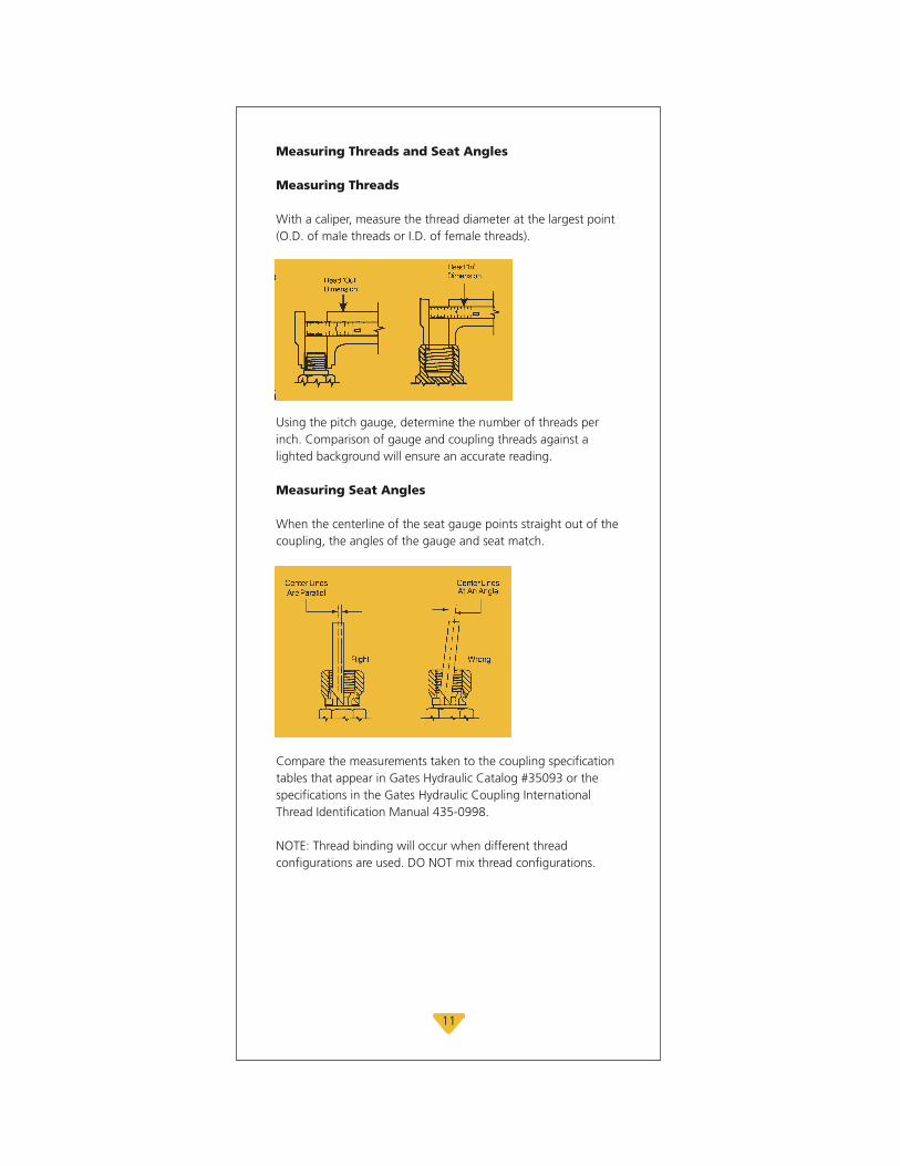
Measuring Threads and Seat Angles
Measuring Threads
With a caliper, measure the thread diameter at the largest point(O.D. of male threads or I.D. of female threads).
Using the pitch gauge, determine the number of threads perinch. Comparison of gauge and coupling threads against alighted background will ensure an accurate reading.
Measuring Seat Angles
When the centerline of the seat gauge points straight out of thecoupling, the angles of the gauge and seat match.
Compare the measurements taken to the coupling specificationtables that appear in Gates Hydraulic Catalog #35093 or thespecifications in the Gates Hydraulic Coupling InternationalThread Identification Manual 435-0998.
NOTE: Thread binding will occur when different thread configurations are used. DO NOT mix thread configurations.

12
How to Make Hose Assemblies of Specific Lengths
Select the hose and couplings required to make the desired hydraulic assembly. Measure the entire length of the assembly.Then use the formula below to calculate the required hose cutlength for the assembly.
Hose Cut Length = Assembly Overall Length Minus(C1 + C2)
Cut-off value "C" is the length of that part of the coupling notdirectly in contact with or applied to the hose. Therefore, subtractthe two "C" values from the total length of the assembly andyou will have the approximate hose length to be replaced.
SAE Length Tolerances for Hydraulic Hose Assembliesand Specified Hose Lengths (Reprinted from National HoseAssemblies Manufacturers Association NHAM-STD-2)
Length Tolerance
For cut lengths from 0 up to and including 12" ±1/8"For cut lengths above 12" up to and including 18" ±3/16"For cut lengths above 18" up to and including 36" ±1/4"For cut lengths above 36" +1% of length measured to
the nearest 1/8"

HOSE ROUTING
Many assemblies fail because of improper routing. To minimizedamage caused by excessive flexing or whipping, all replacementhose should be restrained, protected or guided using clamps.Protective armor, spring guards or sleeves made of abrasion-,temperature- or chemical-resistant material will help protect hosefrom cuts, abrasions, corrosives or hot components. Here are somehose routing tips that will prevent unnecessary assembly failures:
Length Change
When hose installation is straight, allow enough slack in hose line toprovide for length changes that willoccur when pressure is applied.
Movement/Flexing
Adequate hose length is necessary to distribute movement on flexing applications and to avoid abrasion.
Tight Bend
1. When radius is below the requiredminimum, use an angle adapter toavoid sharp bends.
2. Use proper angle adapters to avoid tight bends in hose.
13

Twist
1. Prevent twisting and distortion by bending hose in same plane as the motion of the port to which hose is connected.
2. When installing hose, make sure it is not twisted. Pressure applied to a twisted hose can result in hose failure or loosening of connections.
3. Avoid twisting of hose lines bent in two planes by clamping hose at change of plane.
Strain
Elbows and adapters should be used to relieve strain on the assembly, and to provide neater installations whichwill be more accessible for inspectionand maintenance.
Abrasion
Run hose in the installation so that itavoids rubbing and abrasion. Often,clamps are required to support longhose runs or to keep hose away frommoving parts. Use clamps of the correct size. Too large a clamp allows hose to move inside the clamp and cause wear.
14

Collapse
To avoid hose collapse and flow restriction, keep hose bend radius as large as possible. Refer to hose specification tables for minimum bend radius.
High Heat
High ambient temperatures shortenhose life, so make sure hose is keptaway from hot parts. If this is not possible, insulate hose with GatesHeatGuard™ protective sleeving.
Reduce Connections
Reduce the number of pipe threadjoints by using hydraulic adapters instead of pipe fittings.
Appearance
Route hose directly by using 45° and/or 90° adapters and fittings. Avoid excessive hose length to improve appearance.
15
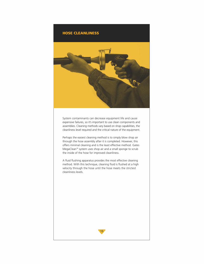
HOSE CLEANLINESS
System contaminants can decrease equipment life and causeexpensive failures, so it’s important to use clean components andassemblies. Cleaning methods vary based on shop capabilities, thecleanliness level required and the critical nature of the equipment.
Perhaps the easiest cleaning method is to simply blow shop airthrough the hose assembly after it is completed. However, thisoffers minimal cleaning and is the least effective method. GatesMegaClean™ system uses shop air and a small sponge to scrubthe inside of the hose for improved cleanliness.
A fluid flushing apparatus provides the most effective cleaningmethod. With this technique, cleaning fluid is flushed at a highvelocity through the hose until the hose meets the strictestcleanliness levels.
16

ASSEMBLY INSTALLATION
Be sure to follow these seven steps when installing a hydraulic assembly:
1. Clean the surrounding area where the connection will be made. Do not let dirt orcontaminants into the opening.
2. If adapters are used, install them now.
3. Lay the hose assembly into the routing position to verify length and correct routing.
4. Thread one end of the assembly onto the port or adapter. Install angled fitting first to ensure proper positioning.
5. Now, thread the other end of the assembly, taking care not to twist the hose. Use a wrench on the fitting’s backup hex while tightening.
6. Properly torque both ends.
7. Run the hydraulic system under low pressure and inspect forleaks and potentially damaging contact points.
1
2
3
4
5
6
7
17
18
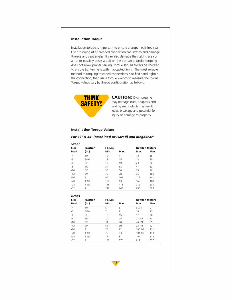
Installation Torque
Installation torque is important to ensure a proper leak-free seal.Over-torquing of a threaded connection can stretch and damagethreads and seat angles. It can also damage the staking area ofa nut or possibly break a bolt on the port area. Under-torquingdoes not allow proper sealing. Torque should always be checkedto ensure tightening is within accepted limits. The most reliablemethod of torquing threaded connections is to first hand-tightenthe connection, then use a torque wrench to measure the torque.Torque values vary by thread configuration as follows:
CAUTION: Over-torquingmay damage nuts, adapters andsealing seats which may result inleaks, breakage and potential forinjury or damage to property.
Installation Torque Values
For 37° & 45° (Machined or Flared) and MegaSeal®
SteelSize Fraction Ft.-Lbs. Newton-MetersDash (In.) Min. Max. Min. Max.
-4 1/4 10 11 13 15-5 5/16 13 15 18 20-6 3/8 17 19 23 26-8 1/2 34 38 47 52-10 5/8 50 56 69 76-12 3/4 70 78 96 106-16 1 94 104 127 141-20 1 1/4 124 138 169 188-24 1 1/2 156 173 212 235-32 2 219 243 296 329
BrassSize Fraction Ft.-Lbs. Newton-MetersDash (In.) Min. Max. Min. Max.
-4 1/4 5 6 6-3/4 9-5 5/16 7 9 10 13-6 3/8 12 15 17 20-8 1/2 20 24 27 2/3 33-10 5/8 34 40 46 1/3 55-12 3/4 53 60 72 1/3 82-16 1 74 82 100 1/2 111-20 1 1/4 75 83 101 1/2 113-24 1 1/2 79 87 107 118-32 2 158 175 214 237
19
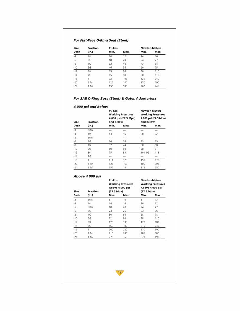
For Flat-Face O-Ring Seal (Steel)
Size Fraction Ft.-Lbs. Newton-MetersDash (In.) Min. Max. Min. Max.
-4 1/4 10 12 14 16-6 3/8 18 20 24 27-8 1/2 32 40 43 54-10 5/8 46 56 60 75-12 3/4 65 80 90 110-14 7/8 65 80 90 110-16 1 92 105 125 240-20 1 1/4 125 140 170 190-24 1 1/2 150 180 200 245
For SAE O-Ring Boss (Steel) & Gates Adapterless
4,000 psi and belowFt.-Lbs. Newton-MetersWorking Pressures Working Pressures4,000 psi (27.5 Mpa) 4,000 psi (27.5 Mpa)
Size Fraction and below and belowDash (In.) Min. Max. Min. Max.
-3 3/16 — — — —-4 1/4 14 16 20 22-5 5/16 — — — —-6 3/8 24 26 33 35-8 1/2 37 44 50 60-10 5/8 50 60 68 81-12 3/4 75 83 101 1/2 113-14 7/8 — — — —-16 1 111 125 150 170-20 1 1/4 133 152 180 206-24 1 1/2 156 184 212 250
Above 4,000 psiFt.-Lbs. Newton-MetersWorking Pressures Working PressuresAbove 4,000 psi Above 4,000 psi
Size Fraction (27.5 Mpa) (27.5 Mpa)Dash (In.) Min. Max. Min. Max.
-3 3/16 8 10 11 13-4 1/4 14 16 20 22-5 5/16 18 20 24 27-6 3/8 24 26 33 35-8 1/2 50 60 68 78-10 5/8 72 80 98 110-12 3/4 125 135 170 183-14 7/8 160 180 215 245-16 1 200 220 270 300-20 1 1/4 210 280 285 380-24 1 1/2 270 360 370 490

20
For BSP 30° Inverted Cone
Size Fraction Ft.-Lbs. Newton-MetersDash (In.) Min. Max. Min. Max.
-2 1/8 7 9 9 12-4 1/4 11 18 15 24-6 3/8 19 28 26 38-8 1/2 30 36 41 49-10 5/8 37 44 50 60-12 3/4 50 60 68 81-16 1 79 95 107 129-20 1 1/4 127 152 172 206-24 1 1/2 167 190 226 258-32 2 262 314 355 426
For DIN 2353 12°, 30° and Universal Inverted Cone
SizeLight HeavySeries Series Tube O.D. Tube O.D. Ft-Lbs. Newton-Meters(dash) (dash) Min. Max. Min. Max.
-6 — 7 15 10 20-8 — 15 26 20 35-10 -8 18 30 25 40-12 -10 22 33 30 45-14 -12 26 37 35 50-15 -14 30 52 40 70 — -16 30 52 40 70-18 — 44 74 60 100-22 -20 59 89 80 120-28 -25 74 111 100 150— -30 74 163 150 220-35 — 133 184 180 250-42 -38 148 221 200 300

PERIODIC INSPECTIONS
Periodic hose assembly inspections can prevent unwanted andunexpected assembly failures. During normal operations, be awareof how the equipment sounds, feels, etc. Be sure to check anynoticeable abnormalities.
Hose inspection can vary by equipment type. Refer to yourequipment manual and always follow the manufacturer’s inspectionrecommendations. If the recommendations are not available,use the following guidelines:
• Inspect mobile equipment every 400 to 600 hours or every three months, whichever comes first.
• Inspect stationary equipment every three months.
Other factors that influence inspections include:• Whether the equipment is critical to the operation• Operating pressures and temperatures• Difficult routing conditions• Extreme environmental factors• Accessibility of equipment
Inspection Procedures
Here’s a checklist to help keep your equipment running strong:1.First, turn off and lock out the equipment’s power.2.Place the equipment and components in a safe
and/or neutral position.3.Remove access panels and inspect hose and
fittings for damage or leaks.4.Repair or replace assemblies as needed.5. Inspect other hydraulic components.6.Reinstall access panels.7.Turn power back on.8.Pay attention to unusual noises, vibrations, etc.
21

HOSE TROUBLESHOOTING
The goal of troubleshooting is to identify the cause or causes ofa hose failure, and then take the appropriate corrective action.Here’s a list of some common causes of premature hose failureand some everyday solutions to correct the problems:
Hose Abrasion
Solution – Reroute the hose to keep itaway from abrasive sources or guard thehose with a protective sleeve.
Hose Burst Away from Hose Ends
Solution – Inspect system operatingpressure and select a hose that meets orexceeds the system’s maximum pressure.Try rerouting the hose to prevent excessive flexing or keep thehose from exceeding its minimum bend radius.
Hose Burst at Coupling
Solution – Increase the hose assembly’slength to accommodate contraction underpressure; increase the hose bend radius or install bend restrictors; or replace the hose assembly with aproperly crimped assembly.
Leak at Thread End/Seat
Solutions:Remove the connection and inspect.
1. Certain couplings require the use of an O-ring. If it’s missing, replace it. If an O-ring is used, check for damage caused duringinstallation or possible material breakdown from heat or fluid incompatibility. Alternative O-ring materials may be required. Replace if necessary.
2. Check the threads and/or seat angle on both mating surfaces for damage that may have occurred prior to or during installation.Any ding or burr may be a potential leak path. Replace if necessary.
22

3. If the coupling was misaligned during installation, threads may have been damaged. Replace and carefully install.
4. It is possible to thread together some components that are not compatible. Use Gates thread I.D. kit to assist in identifying matingcomponents. Some thread end configurations have better sealability than others. Also, ensure proper coupling selection.
5. Over-torquing of a threaded connection can damage threads and mating seat angles. Over-torquing can also damage the staking area of the nut causing cracking of either the nut or seat. Under-torquing does not allow proper sealing. Use of a torque wrench can alleviate such problems.
Weep/Seep at Hose Coupling Interface
Solution – Whether it has been under-crimped or the stem has been improperlyinserted, the hose assembly must be replaced with one that has been properlyassembled.
Coupling Blow-Off
Solution – Examine and replace the hose assembly to ensure proper assemblyprocedures are followed. Modify hoselength and/or routing to accommodate potential hose length reduction under pressure. Never mix different manufacturers’hose, couplings or crimpers.
Hose Cracks
Solution – Select a hose that meets thetemperature and flow requirements of theapplication. Also, identify the heat sourceand consider rerouting it away from the source to minimize theeffects. Examine reservoir size (if necessary).
23

Hose Twist
Solution – Replace and reroute the hoseto ensure that bending occurs only in oneplane. The use of bent tube or block stylecouplings and adapters may improve routing. Also, when installingthe assembly, hold the backup hex to prevent it from turningand applying a twist. If male and female couplings are used onthe same hose assembly, install the male (non-swivel) end first.
Cover Blisters
Solution – Replace the hose with onethat is recommended as compatible withthe fluid being used. If it is compressedgas, the cover can also be perforated (pin-pricked) to allow thegas to seep through the cover. Textile hose covers also eliminateblistering. Bleed the system to eliminate any trapped air.

SAFE HYDRAULICS
There you have it – an overview of hydraulic safety and preventivemaintenance. If you are looking for more information on this topic,Gates offers a special hydraulic preventive maintenance trainingprogram called “Safe Hydraulics.” The class provides you witheverything you need to know to properly maintain your hydraulicequipment for safe operation:
• Fitting orientation• Coupling identification• Agency specifications• Hydraulic fluids• Hose storage life• Proper installation
torque values• Crimper preventive
maintenance• Troubleshooting
For more information, contact your local Gates hydraulic distributoror visit us online at www.gates.com/safehydraulics
25

The World’s Most Trusted Name in Belts, Hose and Hydraulics.
Gates CorporationP.O. Box 5887Denver, CO 80217-5887800-777-6363www.gates.com
©2008 Gates Corporation Printed in U.S.A. 39595-P 6/08


