17
Hydraulics, Inc. FS SERIES HIGH TORQUE, HIGH SPEED RADIAL PISTON HYDRAULIC MOTORS Technical Catalog
Hydraulics, Inc.
FS SERIES
HIGH TORQUE, HIGH SPEED
RADIAL PISTON HYDRAULIC MOTORS
Technical Catalog
Hydraulics, Inc.
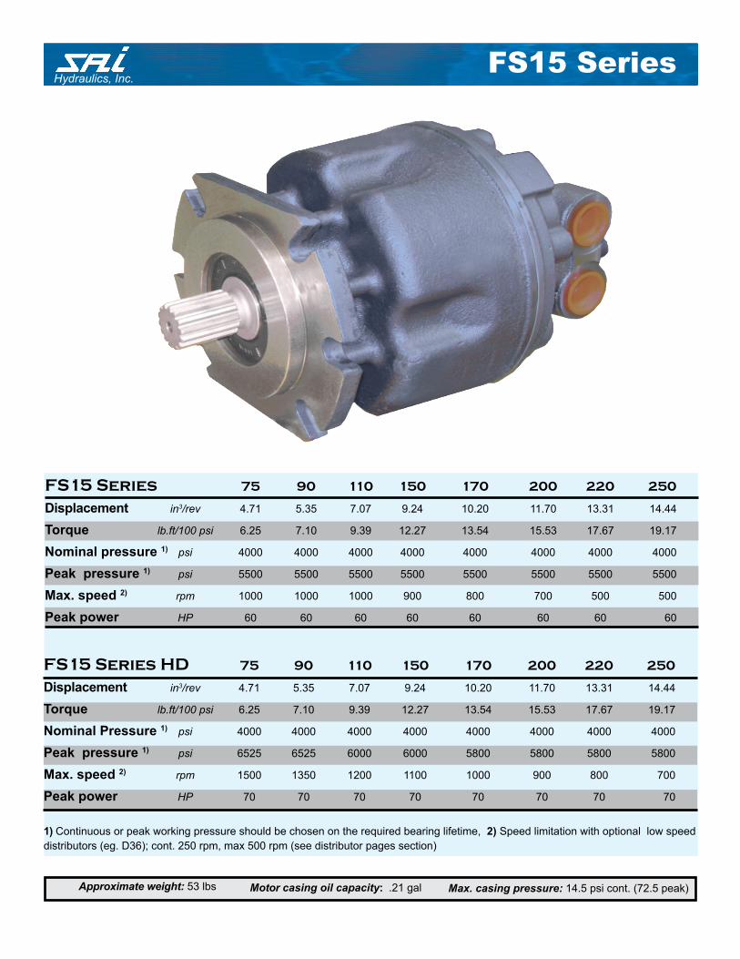
FS15 Series 75 90 110 150 170 200 220 250
Displacement in3/rev 4.71 5.35 7.07 9.24 10.20 11.70 13.31 14.44
Torque lb.ft/100 psi 6.25 7.10 9.39 12.27 13.54 15.53 17.67 19.17
Nominal pressure 1) psi 4000 4000 4000 4000 4000 4000 4000 4000
Peak pressure 1) psi 5500 5500 5500 5500 5500 5500 5500 5500
Max. speed 2) rpm 1000 1000 1000 900 800 700 500 500
Peak power HP 60 60 60 60 60 60 60 60
Max. casing pressure: 14.5 psi cont. (72.5 peak)Approximate weight: 53 lbs Motor casing oil capacity: .21 gal
1) Continuous or peak working pressure should be chosen on the required bearing lifetime, 2) Speed limitation with optional low speed
distributors (eg. D36); cont. 250 rpm, max 500 rpm (see distributor pages section)
FS15 Series
FS15 Series HD 75 90 110 150 170 200 220 250
Displacement in3/rev 4.71 5.35 7.07 9.24 10.20 11.70 13.31 14.44
Torque lb.ft/100 psi 6.25 7.10 9.39 12.27 13.54 15.53 17.67 19.17
Nominal Pressure 1) psi 4000 4000 4000 4000 4000 4000 4000 4000
Peak pressure 1) psi 6525 6525 6000 6000 5800 5800 5800 5800
Max. speed 2) rpm 1500 1350 1200 1100 1000 900 800 700
Peak power HP 70 70 70 70 70 70 70 70
Hydraulics, Inc.
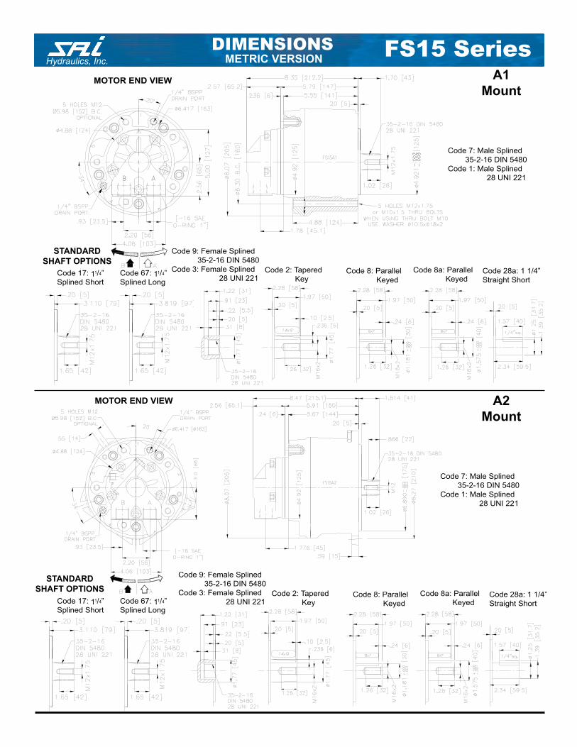
Code 9: Female Splined
35-2-16 DIN 5480
Code 3: Female Splined
28 UNI 221
DIMENSIONSMETRIC VERSION
STANDARD
SHAFT OPTIONSCode 8: Parallel
Keyed
STANDARD
SHAFT OPTIONS
A1
Mount
A2
Mount
MOTOR END VIEW
Code 7: Male Splined
35-2-16 DIN 5480
Code 1: Male Splined
28 UNI 221
MOTOR END VIEW
Code 28a: 1 1/4”
Straight Short
Code 2: Tapered
Key
Code 8a: Parallel
Keyed
Code 7: Male Splined
35-2-16 DIN 5480
Code 1: Male Splined
28 UNI 221
Code 9: Female Splined
35-2-16 DIN 5480
Code 3: Female Splined
28 UNI 221Code 8: Parallel
Keyed
Code 28a: 1 1/4”
Straight Short
Code 2: Tapered
Key
Code 8a: Parallel
Keyed
FS15 Series
Code 17: 11/4”
Splined Short
Code 67: 11/4”
Splined Long
Code 17: 11/4”
Splined Short
Code 67: 11/4”
Splined Long
Hydraulics, Inc.
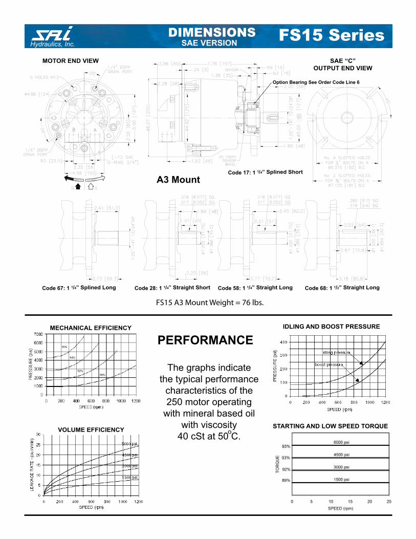
Code 58: 1 1/4” Straight Long
The graphs indicate
the typical performance
characteristics of the
250 motor operating
with mineral oil
with viscosity
40 cSt at 50°C.
PERFORMANCE
Code 28: 1 1/4” Straight ShortCode 67: 1 1/4” Splined Long Code 68: 1 1/2” Straight Long
95%
94%
92%
90%
MECHANICAL EFFICIENCY IDLING AND BOOST PRESSURE
VOLUME EFFICIENCY
Code 17: 1 1/4” Splined Short
SAE “C”
OUTPUT END VIEW
MOTOR END VIEW
STARTING AND LOW SPEED TORQUE
A3 Mount
DIMENSIONSSAE VERSION
Option Bearing See Order Code Line 6
The graphs indicate
the typical performance
characteristics of the
250 motor operating
with mineral based oil
with viscosity
40 cSt at 50 C.o
FS15 A3 Mount Weight = 76 lbs.
FS15 Series
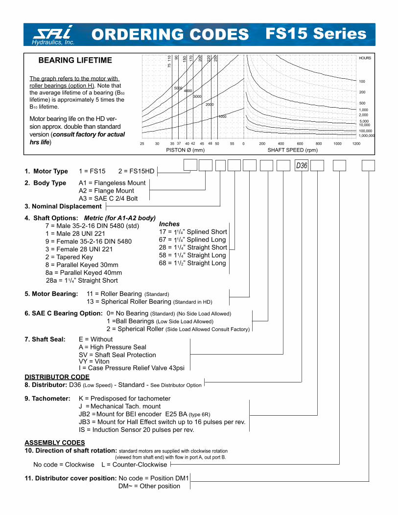
Hydraulics, Inc.ORDERING CODES
SHAFT SPEED (rpm)PISTON Ø (mm)
The graph refers to the motor with
roller bearings (option H). Note that
the average lifetime of a bearing (B50
lifetime) is approximately 5 times the
B10 lifetime.
BEARING LIFETIME
Motor bearing life on the HD ver-
sion approx. double than standard
version (consult factory for actual
hrs life)
1. Motor Type 1 = FS15 2 = FS15HD
2. Body Type A1 = Flangeless Mount
A2 = Flange Mount
A3 = SAE C 2/4 Bolt
3. Nominal Displacement
4. Shaft Options: Metric (for A1-A2 body)
7 = Male 35-2-16 DIN 5480 (std)
1 = Male 28 UNI 221
9 = Female 35-2-16 DIN 5480
3 = Female 28 UNI 221
2 = Tapered Key
8 = Parallel Keyed 30mm
8a = Parallel Keyed 40mm
28a = 11/4” Straight Short
5. Motor Bearing: 11 = Roller Bearing (Standard)
13 = Spherical Roller Bearing (Standard in HD)
6. SAE C Bearing Option: 0= No Bearing (Standard) (No Side Load Allowed)
1 =Ball Bearings (Low Side Load Allowed)
2 = Spherical Roller (Side Load Allowed Consult Factory)
7. Shaft Seal: E = Without
A = High Pressure Seal
SV = Shaft Seal Protection VY = Viton I = Case Pressure Relief Valve 43psi
DISTRIBUTOR CODE
8. Distributor: D36 (Low Speed) - Standard - See Distributor Option
9. Tachometer: K = Predisposed for tachometer
J = Mechanical Tach. mount
JB2 = Mount for BEI encoder E25 BA (type 6R)
JB3 = Mount for Hall Effect switch up to 16 pulses per rev.
IS = Induction Sensor 20 pulses per rev.
ASSEMBLY CODES
10. Direction of shaft rotation: standard motors are supplied with clockwise rotation
(viewed from shaft end) with fl ow in port A, out port B.
No code = Clockwise L = Counter-Clockwise
11. Distributor cover position: No code = Position DM1
DM~ = Other position
Inches
17 = 11/4” Splined Short
67 = 11/4” Splined Long
28 = 11/4” Straight Short
58 = 11/4” Straight Long
68 = 11/2” Straight Long
D36
150
220
0 200 400 600 800 1000 1200
100
1,000
10,000
100,000
1,000,000
200
500
2,000
5,000
HOURS
25 30 35 40 45 50 55
170
200
250
4000
2000
1000
3000
5000
90
75 110
37 42 48
FS15 Series
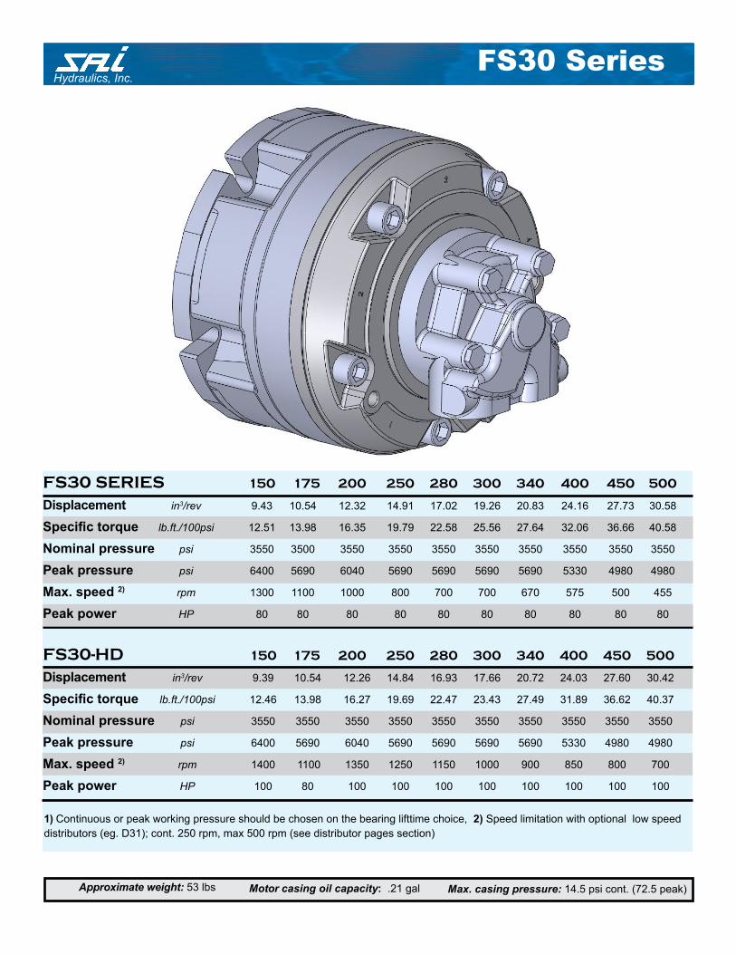
Hydraulics, Inc.FS30 Series
Max. casing pressure: 14.5 psi cont. (72.5 peak)Approximate weight: 53 lbs Motor casing oil capacity: .21 gal
1) Continuous or peak working pressure should be chosen on the bearing lifttime choice, 2) Speed limitation with optional low speed
distributors (eg. D31); cont. 250 rpm, max 500 rpm (see distributor pages section)
FS30 SERIES 150 175 200 250 280 300 340 400 450 500
Displacement in3/rev 9.43 10.54 12.32 14.91 17.02 19.26 20.83 24.16 27.73 30.58
Specifi c torque lb.ft./100psi 12.51 13.98 16.35 19.79 22.58 25.56 27.64 32.06 36.66 40.58
Nominal pressure psi 3550 3500 3550 3550 3550 3550 3550 3550 3550 3550
Peak pressure psi 6400 5690 6040 5690 5690 5690 5690 5330 4980 4980
Max. speed 2) rpm 1300 1100 1000 800 700 700 670 575 500 455
Peak power HP 80 80 80 80 80 80 80 80 80 80
FS30-HD 150 175 200 250 280 300 340 400 450 500
Displacement in3/rev 9.39 10.54 12.26 14.84 16.93 17.66 20.72 24.03 27.60 30.42
Specifi c torque lb.ft./100psi 12.46 13.98 16.27 19.69 22.47 23.43 27.49 31.89 36.62 40.37
Nominal pressure psi 3550 3550 3550 3550 3550 3550 3550 3550 3550 3550
Peak pressure psi 6400 5690 6040 5690 5690 5690 5690 5330 4980 4980
Max. speed 2) rpm 1400 1100 1350 1250 1150 1000 900 850 800 700
Peak power HP 100 80 100 100 100 100 100 100 100 100
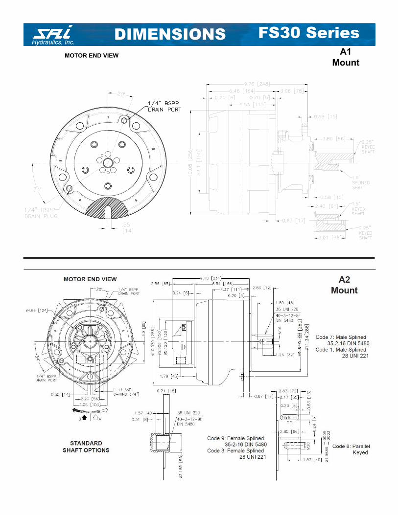
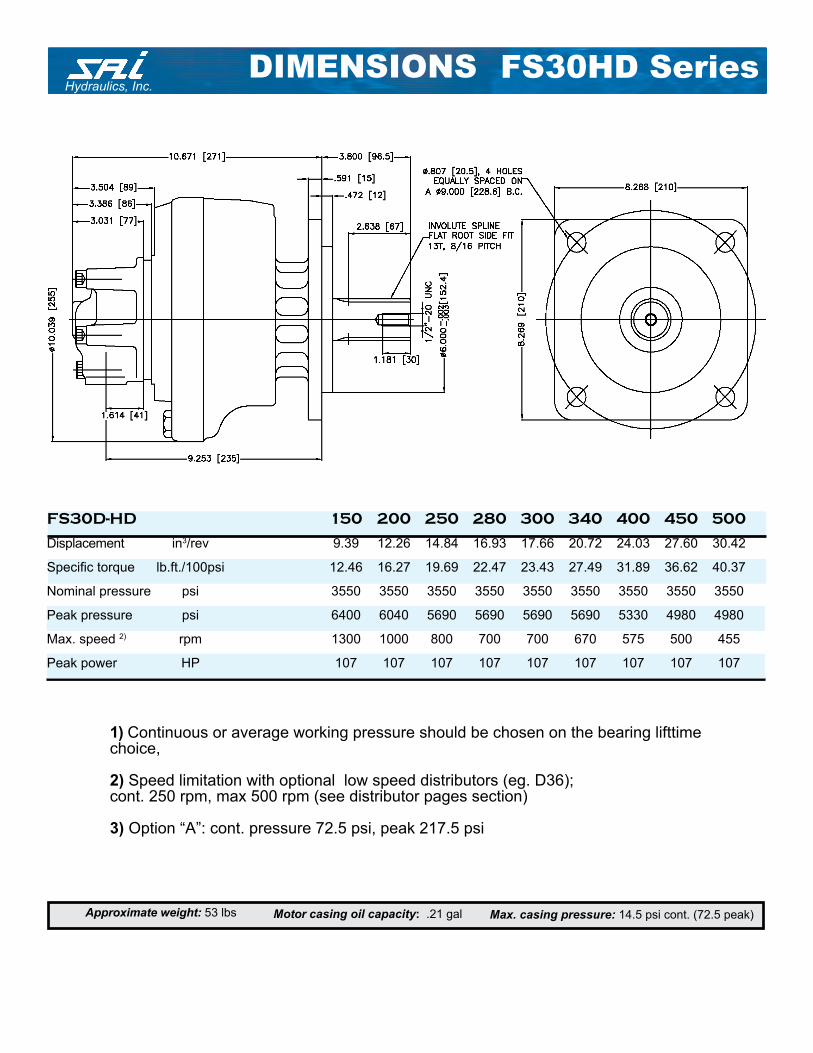
Hydraulics, Inc.FS30 SeriesDIMENSIONS
A1
MountMOTOR END VIEW
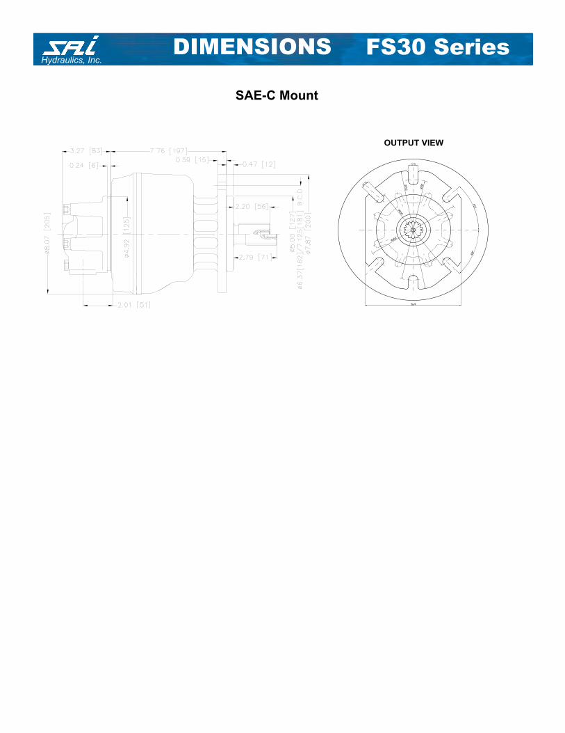
Hydraulics, Inc.DIMENSIONS FS30 Series
SAE-C Mount
OUTPUT VIEW
Hydraulics, Inc.
1) Continuous or average working pressure should be chosen on the bearing lifttime choice,
2) Speed limitation with optional low speed distributors (eg. D36); cont. 250 rpm, max 500 rpm (see distributor pages section)
3) Option “A”: cont. pressure 72.5 psi, peak 217.5 psi
Max. casing pressure: 14.5 psi cont. (72.5 peak)Approximate weight: 53 lbs Motor casing oil capacity: .21 gal
FS30D-HD 150 200 250 280 300 340 400 450 500
Displacement in3/rev 9.39 12.26 14.84 16.93 17.66 20.72 24.03 27.60 30.42
Specifi c torque lb.ft./100psi 12.46 16.27 19.69 22.47 23.43 27.49 31.89 36.62 40.37
Nominal pressure psi 3550 3550 3550 3550 3550 3550 3550 3550 3550
Peak pressure psi 6400 6040 5690 5690 5690 5690 5330 4980 4980
Max. speed 2) rpm 1300 1000 800 700 700 670 575 500 455
Peak power HP 107 107 107 107 107 107 107 107 107
DIMENSIONS FS30HD Series
Hydraulics, Inc.FS30 Series
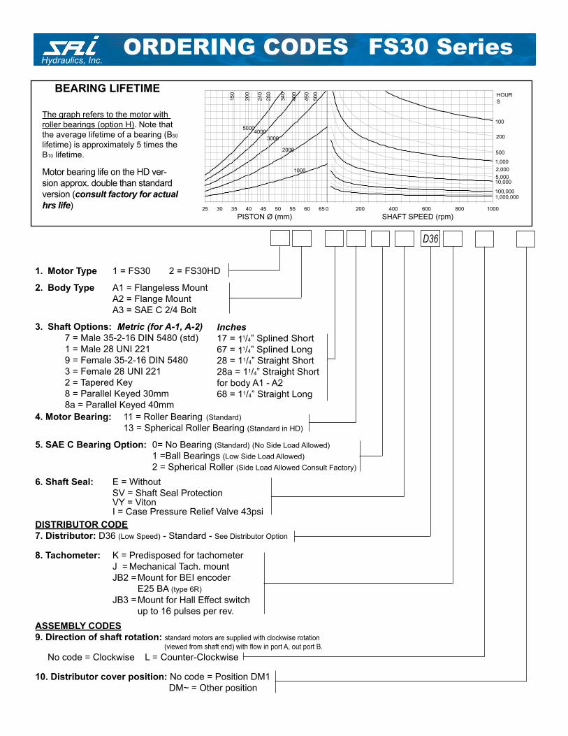
SHAFT SPEED (rpm)PISTON Ø (mm)
The graph refers to the motor with
roller bearings (option H). Note that
the average lifetime of a bearing (B50
lifetime) is approximately 5 times the
B10 lifetime.
BEARING LIFETIME
Motor bearing life on the HD ver-
sion approx. double than standard
version (consult factory for actual
hrs life) 0 200 400 600 800 1000
100
1,000
10,000
100,0001,000,000
200
500
2,000
5,000
HOUR
S
25 30 35 40 45 50 55 60 65
340
400
450
500
4000
2000
1000
3000
5000
280
240
200
150
1. Motor Type 1 = FS30 2 = FS30HD
2. Body Type A1 = Flangeless Mount
A2 = Flange Mount
A3 = SAE C 2/4 Bolt
3. Shaft Options: Metric (for A-1, A-2)
7 = Male 35-2-16 DIN 5480 (std)
1 = Male 28 UNI 221
9 = Female 35-2-16 DIN 5480
3 = Female 28 UNI 221
2 = Tapered Key
8 = Parallel Keyed 30mm
8a = Parallel Keyed 40mm
4. Motor Bearing: 11 = Roller Bearing (Standard)
13 = Spherical Roller Bearing (Standard in HD)
5. SAE C Bearing Option: 0= No Bearing (Standard) (No Side Load Allowed)
1 =Ball Bearings (Low Side Load Allowed)
2 = Spherical Roller (Side Load Allowed Consult Factory)
6. Shaft Seal: E = Without
SV = Shaft Seal Protection VY = Viton I = Case Pressure Relief Valve 43psi
DISTRIBUTOR CODE
7. Distributor: D36 (Low Speed) - Standard - See Distributor Option
8. Tachometer: K = Predisposed for tachometer
J = Mechanical Tach. mount
JB2 = Mount for BEI encoder
E25 BA (type 6R)
JB3 = Mount for Hall Effect switch
up to 16 pulses per rev.
ASSEMBLY CODES
9. Direction of shaft rotation: standard motors are supplied with clockwise rotation
(viewed from shaft end) with fl ow in port A, out port B.
No code = Clockwise L = Counter-Clockwise
10. Distributor cover position: No code = Position DM1
DM~ = Other position
Inches
17 = 11/4” Splined Short
67 = 11/4” Splined Long
28 = 11/4” Straight Short
28a = 11/4” Straight Short
for body A1 - A2
68 = 11/4” Straight Long
D36
ORDERING CODES
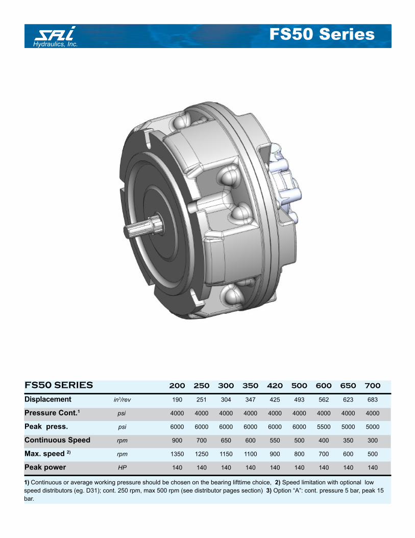
Hydraulics, Inc.FS50 Series
1) Continuous or average working pressure should be chosen on the bearing lifttime choice, 2) Speed limitation with optional low
speed distributors (eg. D31); cont. 250 rpm, max 500 rpm (see distributor pages section) 3) Option “A”: cont. pressure 5 bar, peak 15
bar.
FS50 SERIES 200 250 300 350 420 500 600 650 700
Displacement in3/rev 190 251 304 347 425 493 562 623 683
Pressure Cont.1 psi 4000 4000 4000 4000 4000 4000 4000 4000 4000
Peak press. psi 6000 6000 6000 6000 6000 6000 5500 5000 5000
Continuous Speed rpm 900 700 650 600 550 500 400 350 300
Max. speed 2) rpm 1350 1250 1150 1100 900 800 700 600 500
Peak power HP 140 140 140 140 140 140 140 140 140

Hydraulics, Inc.FS50 SeriesDIMENSIONS
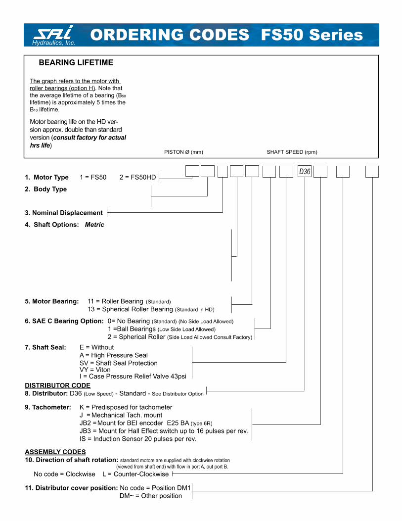
Hydraulics, Inc.FS50 SeriesORDERING CODES
The graph refers to the motor with
roller bearings (option H). Note that
the average lifetime of a bearing (B50
lifetime) is approximately 5 times the
B10 lifetime.
BEARING LIFETIME
Motor bearing life on the HD ver-
sion approx. double than standard
version (consult factory for actual
hrs life)
1. Motor Type 1 = FS50 2 = FS50HD
2. Body Type
3. Nominal Displacement
4. Shaft Options: Metric
5. Motor Bearing: 11 = Roller Bearing (Standard)
13 = Spherical Roller Bearing (Standard in HD)
6. SAE C Bearing Option: 0= No Bearing (Standard) (No Side Load Allowed)
1 =Ball Bearings (Low Side Load Allowed)
2 = Spherical Roller (Side Load Allowed Consult Factory)
7. Shaft Seal: E = Without
A = High Pressure Seal
SV = Shaft Seal Protection VY = Viton I = Case Pressure Relief Valve 43psi
DISTRIBUTOR CODE
8. Distributor: D36 (Low Speed) - Standard - See Distributor Option
9. Tachometer: K = Predisposed for tachometer
J = Mechanical Tach. mount
JB2 = Mount for BEI encoder E25 BA (type 6R)
JB3 = Mount for Hall Effect switch up to 16 pulses per rev.
IS = Induction Sensor 20 pulses per rev.
ASSEMBLY CODES
10. Direction of shaft rotation: standard motors are supplied with clockwise rotation
(viewed from shaft end) with fl ow in port A, out port B.
No code = Clockwise L = Counter-Clockwise
11. Distributor cover position: No code = Position DM1
DM~ = Other position
D36
SHAFT SPEED (rpm)PISTON Ø (mm)
Hydraulics, Inc.FS507 Series

Hydraulics, Inc.FS507 SeriesDIMENSIONS
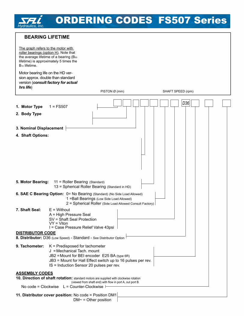
Hydraulics, Inc.FS507 SeriesORDERING CODES
The graph refers to the motor with
roller bearings (option H). Note that
the average lifetime of a bearing (B50
lifetime) is approximately 5 times the
B10 lifetime.
BEARING LIFETIME
Motor bearing life on the HD ver-
sion approx. double than standard
version (consult factory for actual
hrs life)
1. Motor Type 1 = FS507
2. Body Type
3. Nominal Displacement
4. Shaft Options:
5. Motor Bearing: 11 = Roller Bearing (Standard)
13 = Spherical Roller Bearing (Standard in HD)
6. SAE C Bearing Option: 0= No Bearing (Standard) (No Side Load Allowed)
1 =Ball Bearings (Low Side Load Allowed)
2 = Spherical Roller (Side Load Allowed Consult Factory)
7. Shaft Seal: E = Without
A = High Pressure Seal
SV = Shaft Seal Protection VY = Viton I = Case Pressure Relief Valve 43psi
DISTRIBUTOR CODE
8. Distributor: D36 (Low Speed) - Standard - See Distributor Option
9. Tachometer: K = Predisposed for tachometer
J = Mechanical Tach. mount
JB2 = Mount for BEI encoder E25 BA (type 6R)
JB3 = Mount for Hall Effect switch up to 16 pulses per rev.
IS = Induction Sensor 20 pulses per rev.
ASSEMBLY CODES
10. Direction of shaft rotation: standard motors are supplied with clockwise rotation
(viewed from shaft end) with fl ow in port A, out port B.
No code = Clockwise L = Counter-Clockwise
11. Distributor cover position: No code = Position DM1
DM~ = Other position
D36
SHAFT SPEED (rpm)PISTON Ø (mm)

Hydraulics, Inc.
168 East Ridge Road, Suite 106
Linwood, PA 19061
(610) 497-0190 FAX (610) 497-0197
SAI HYDRAULICS CANADA LTD.
6105 BOULEVARD COUTURE
ST. LEONARD, PQ H 1P3G7
(514) 323-4552 Fax (514) 323-8780


