9
Calculation Example
Splined Shaft According to Niemann
Release July 2013
c© 2013 GWJ Technology GmbHRebenring 31 � 38106 Braunschweig � Tel.: +49 (0) 531 129 399-0
www.eAssistant.eu

Contents
0.1 Calculation Example: Splined Shaft for a Hoist Drive . . . . . . . . . . . . . . . . . . . . . 30.1.1 Start the Calculation Module . . . . . . . . . . . . . . . . . . . . . . . . . . . . . 30.1.2 Input Values . . . . . . . . . . . . . . . . . . . . . . . . . . . . . . . . . . . . . . 30.1.3 The Calculation . . . . . . . . . . . . . . . . . . . . . . . . . . . . . . . . . . . . . 40.1.4 Calculation Results . . . . . . . . . . . . . . . . . . . . . . . . . . . . . . . . . . . 70.1.5 Documentation: Calculation Report . . . . . . . . . . . . . . . . . . . . . . . . . . 70.1.6 How to Save the Calculation . . . . . . . . . . . . . . . . . . . . . . . . . . . . . . 8
2
0.1. Calculation Example: Splined Shaft for Lifting Gear 3
0.1 Calculation Example: Splined Shaft for Lifting Gear
We have prepared the following example to guide you through the calculation module. This calculation ex-ample is based on: G. Niemann, H. Winter, B.-R. Hoehn: Maschinenelemente Band I: Konstruktion vonVerbindungen, Lagern, Wellen. Springer Verlag, 3rd Edition, 2001: p. 857 Example 4: Splined shaft for liftinggear.
0.1.1 Start the Calculation Module
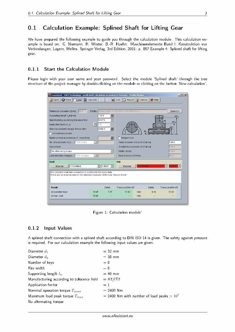
Please login with your user name and your password. Select the module `Splined shaft' through the treestructure of the project manager by double-clicking on the module or clicking on the button `New calculation'.
Figure 1: Calculation module'
0.1.2 Input Values
A splined shaft connection with a splined shaft according to DIN ISO 14 is given. The safety against pressureis required. For our calculation example the following input values are given:
Diameter d1 = 32 mm
Diameter d2 = 38 mm
Number of keys = 8
Key width = 6
Supporting length ltr = 40 mm
Manufacturing according to tolerance �eld = H7/IT7
Application factor = 1
Nominal operation torque Tnenn = 2400 Nm
Maximum load peak torque Tmax = 2400 Nm with number of load peaks > 107
No alternating torque
www.eAssistant.eu
0.1. Calculation Example: Splined Shaft for Lifting Gear 4
Outer diameter of hub D2 = 45 mm
Material shaft = C45 hardened and tempered
Material hub = C45 hardened and tempered
0.1.3 The Calculation
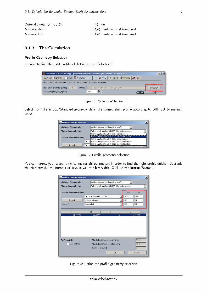
Pro�le Geometry Selection
In order to �nd the right pro�le, click the button `Selection'.
Figure 2: `Selection' button
Select from the listbox `Standard geometry data' the splined shaft pro�le according to DIN ISO 14 mediumseries.
Figure 3: Pro�le geometry selection
You can narrow your search by entering certain parameters in order to �nd the right pro�le quicker. Just addthe diameter d1, the number of keys as well the key width. Click on the button `Search'.
Figure 4: Re�ne the pro�le geometry selection
www.eAssistant.eu
0.1. Calculation Example: Splined Shaft for Lifting Gear 5
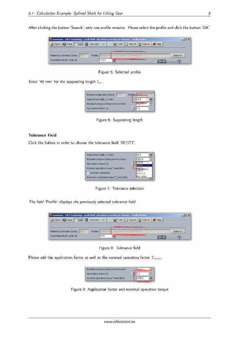
After clicking the button `Search', only one pro�le remains. Please select the pro�le and click the button `OK'.
Figure 5: Selected pro�le
Enter `40 mm' for the supporting length ltr.
Figure 6: Supporting length
Tolerance Field
Click the listbox in order to choose the tolerance �eld `H7/IT7'.
Figure 7: Tolerance selection
The �eld `Pro�le' displays the previously selected tolerance �eld.
Figure 8: Tolerance �eld
Please add the application factor as well as the nominal operation factor Tnenn.
Figure 9: Application factor and nominal operation torque
www.eAssistant.eu
0.1. Calculation Example: Splined Shaft for Lifting Gear 6
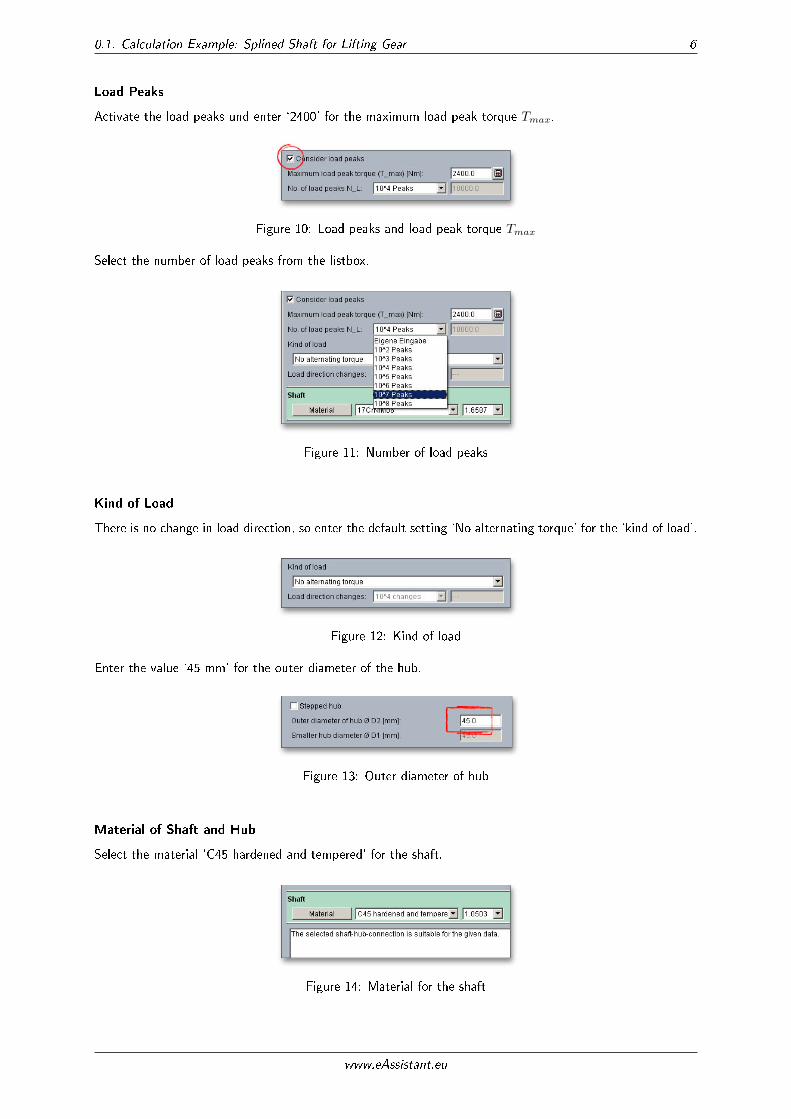
Load Peaks
Activate the load peaks und enter `2400' for the maximum load peak torque Tmax.
Figure 10: Load peaks and load peak torque Tmax
Select the number of load peaks from the listbox.
Figure 11: Number of load peaks
Kind of Load
There is no change in load direction, so enter the default setting `No alternating torque' for the `kind of load'.
Figure 12: Kind of load
Enter the value `45 mm' for the outer diameter of the hub.
Figure 13: Outer diameter of hub
Material of Shaft and Hub
Select the material `C45 hardened and tempered' for the shaft.
Figure 14: Material for the shaft
www.eAssistant.eu
0.1. Calculation Example: Splined Shaft for Lifting Gear 7
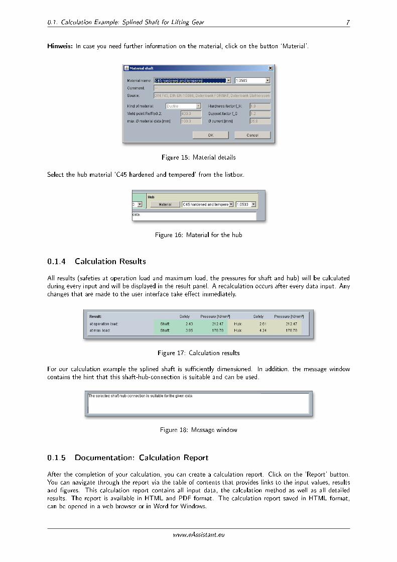
Hinweis: In case you need further information on the material, click on the button `Material'.
Figure 15: Material details
Select the hub material `C45 hardened and tempered' from the listbox.
Figure 16: Material for the hub
0.1.4 Calculation Results
All results (safeties at operation load and maximum load, the pressures for shaft and hub) will be calculatedduring every input and will be displayed in the result panel. A recalculation occurs after every data input. Anychanges that are made to the user interface take e�ect immediately.
Figure 17: Calculation results
For our calculation example the splined shaft is su�ciently dimensioned. In addition, the message windowcontains the hint that this shaft-hub-connection is suitable and can be used.
Figure 18: Message window
0.1.5 Documentation: Calculation Report
After the completion of your calculation, you can create a calculation report. Click on the `Report' button.You can navigate through the report via the table of contents that provides links to the input values, resultsand �gures. This calculation report contains all input data, the calculation method as well as all detailedresults. The report is available in HTML and PDF format. The calculation report saved in HTML format,can be opened in a web browser or in Word for Windows.
www.eAssistant.eu
0.1. Calculation Example: Splined Shaft for Lifting Gear 8
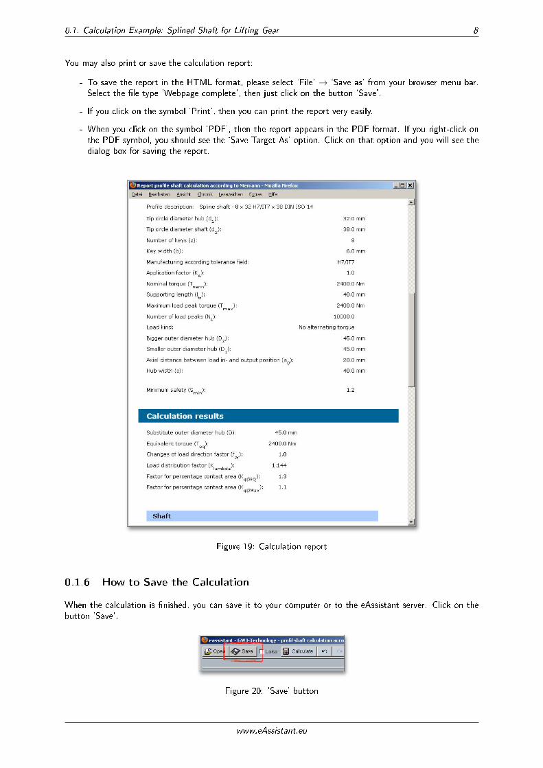
You may also print or save the calculation report:
- To save the report in the HTML format, please select `File' → `Save as' from your browser menu bar.Select the �le type `Webpage complete', then just click on the button `Save'.
- If you click on the symbol `Print', then you can print the report very easily.
- When you click on the symbol `PDF', then the report appears in the PDF format. If you right-click onthe PDF symbol, you should see the `Save Target As' option. Click on that option and you will see thedialog box for saving the report.
Figure 19: Calculation report
0.1.6 How to Save the Calculation
When the calculation is �nished, you can save it to your computer or to the eAssistant server. Click on thebutton `Save'.
Figure 20: `Save' button
www.eAssistant.eu
0.1. Calculation Example: Splined Shaft for Lifting Gear 9
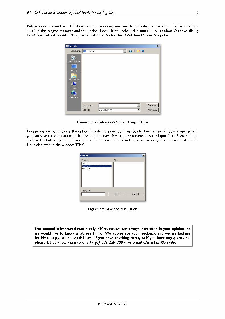
Before you can save the calculation to your computer, you need to activate the checkbox `Enable save datalocal' in the project manager and the option `Local' in the calculation module. A standard Windows dialogfor saving �les will appear. Now you will be able to save the calculation to your computer.
Figure 21: Windows dialog for saving the �le
In case you do not activate the option in order to save your �les locally, then a new window is opened andyou can save the calculation to the eAssistant server. Please enter a name into the input �eld `Filename' andclick on the button `Save'. Then click on the button `Refresh' in the project manager. Your saved calculation�le is displayed in the window `Files'.
Figure 22: Save the calculation
Our manual is improved continually. Of course we are always interested in your opinion, so
we would like to know what you think. We appreciate your feedback and we are looking
for ideas, suggestions or criticism. If you have anything to say or if you have any questions,
please let us know via phone +49 (0) 531 129 399-0 or email [email protected].
www.eAssistant.eu


