Page 1
Copyright © 2016 ON Semiconductor 1
Image Sensors for Vision:
Foundations and Trends Robin Jenkin
May 3, 2016 “This content may contain the proprietary and/or confidential information of Semiconductor Components Industries, LLC (d/b/a “ON Semiconductor”). Such information is being
used with the permission of ON Semiconductor and all rights related to copyrights, trademarks, or any other intellectual property continues to be owned by ON Semiconductor.”
Page 2
Copyright © 2016 ON Semiconductor 2
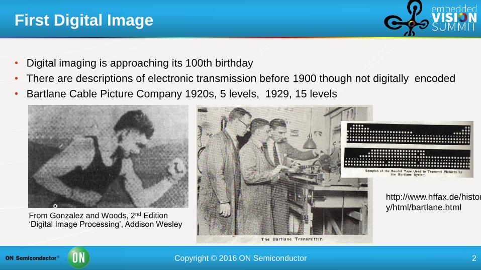
First Digital Image
From Gonzalez and Woods, 2nd Edition ‘Digital Image Processing’, Addison Wesley
http://www.hffax.de/histor
y/html/bartlane.html
• Digital imaging is approaching its 100th birthday
• There are descriptions of electronic transmission before 1900 though not digitally encoded
• Bartlane Cable Picture Company 1920s, 5 levels, 1929, 15 levels
Page 3
Copyright © 2016 ON Semiconductor 3
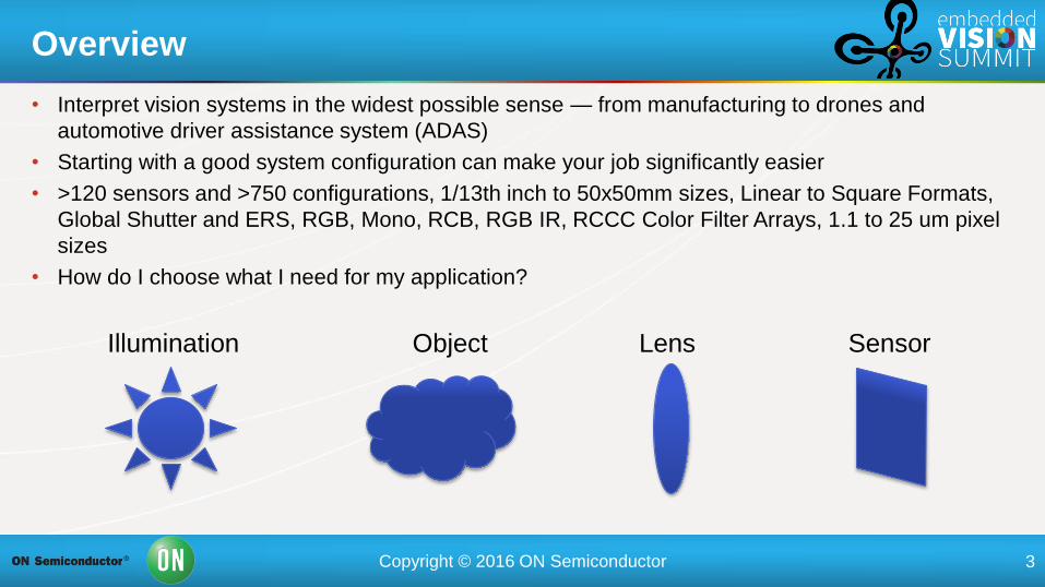
Overview
Illumination Lens Sensor Object
• Interpret vision systems in the widest possible sense — from manufacturing to drones and
automotive driver assistance system (ADAS)
• Starting with a good system configuration can make your job significantly easier
• >120 sensors and >750 configurations, 1/13th inch to 50x50mm sizes, Linear to Square Formats,
Global Shutter and ERS, RGB, Mono, RCB, RGB IR, RCCC Color Filter Arrays, 1.1 to 25 um pixel
sizes
• How do I choose what I need for my application?
Page 4
Copyright © 2016 ON Semiconductor 4
• Pixel size — The size of individual elements on the sensor — measured
in um. 1 to 25 um
• Sensor size — quoted as diagonal in inches or x y size in mm, 1/13th
inch to 50 x 50 mm
• Logical place to start right?
• Object size and working distance
• Iterative process — but lens and object may be better place to start…
Pixel and Sensor Size
Page 5
Copyright © 2016 ON Semiconductor 5
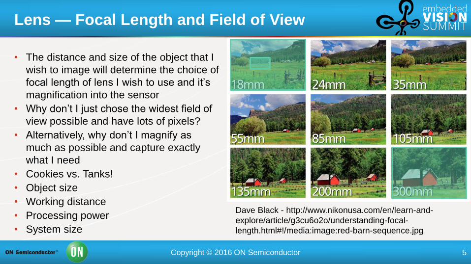
Lens — Focal Length and Field of View
Dave Black - http://www.nikonusa.com/en/learn-and-
explore/article/g3cu6o2o/understanding-focal-
length.html#!/media:image:red-barn-sequence.jpg
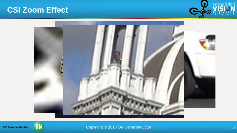
• The distance and size of the object that I
wish to image will determine the choice of
focal length of lens I wish to use and it’s
magnification into the sensor
• Why don’t I just chose the widest field of
view possible and have lots of pixels?
• Alternatively, why don’t I magnify as
much as possible and capture exactly
what I need
• Cookies vs. Tanks!
• Object size
• Working distance
• Processing power
• System size
Page 6
Copyright © 2016 ON Semiconductor 6
CSI Zoom Effect
Page 7
Copyright © 2016 ON Semiconductor 7
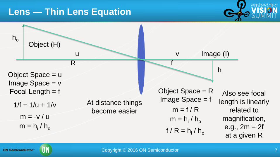
Lens — Thin Lens Equation
u
Object (H)
Image (I) v
ho
hi Object Space = u
Image Space = v
Focal Length = f
1/f = 1/u + 1/v
m = -v / u
m = hi / ho
Object Space = R
Image Space = f
R f
At distance things
become easier
m = f / R
m = hi / ho
f / R = hi / ho
Also see focal
length is linearly
related to
magnification,
e.g., 2m = 2f
at a given R
Page 8
Copyright © 2016 ON Semiconductor 8
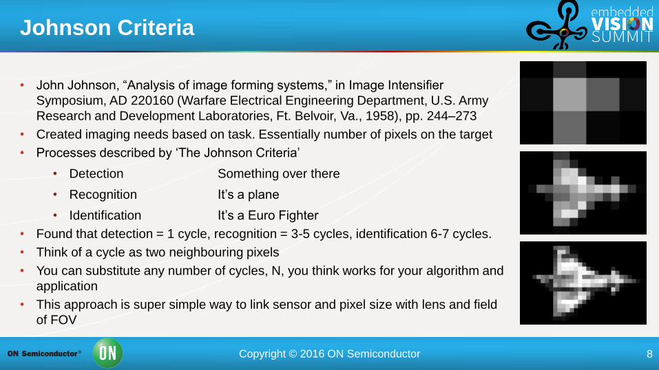
Johnson Criteria
• John Johnson, “Analysis of image forming systems,” in Image Intensifier
Symposium, AD 220160 (Warfare Electrical Engineering Department, U.S. Army
Research and Development Laboratories, Ft. Belvoir, Va., 1958), pp. 244–273
• Created imaging needs based on task. Essentially number of pixels on the target
• Processes described by ‘The Johnson Criteria’
• Detection Something over there
• Recognition It’s a plane
• Identification It’s a Euro Fighter
• Found that detection = 1 cycle, recognition = 3-5 cycles, identification 6-7 cycles.
• Think of a cycle as two neighbouring pixels
• You can substitute any number of cycles, N, you think works for your algorithm and
application
• This approach is super simple way to link sensor and pixel size with lens and field
of FOV
Page 9
Copyright © 2016 ON Semiconductor 9
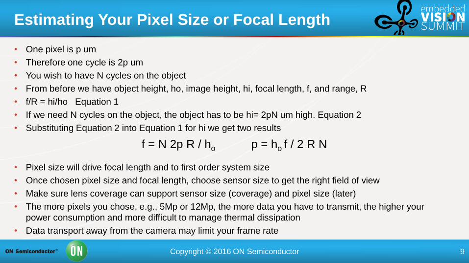
• One pixel is p um
• Therefore one cycle is 2p um
• You wish to have N cycles on the object
• From before we have object height, ho, image height, hi, focal length, f, and range, R
• f/R = hi/ho Equation 1
• If we need N cycles on the object, the object has to be hi= 2pN um high. Equation 2
• Substituting Equation 2 into Equation 1 for hi we get two results
• Pixel size will drive focal length and to first order system size
• Once chosen pixel size and focal length, choose sensor size to get the right field of view
• Make sure lens coverage can support sensor size (coverage) and pixel size (later)
• The more pixels you chose, e.g., 5Mp or 12Mp, the more data you have to transmit, the higher your
power consumption and more difficult to manage thermal dissipation
• Data transport away from the camera may limit your frame rate
Estimating Your Pixel Size or Focal Length
f = N 2p R / ho p = ho f / 2 R N
Page 10
Copyright © 2016 ON Semiconductor 10
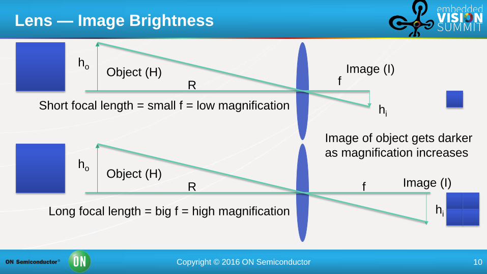
Lens — Image Brightness
R Object (H)
Image (I) f
ho
hi
R Object (H) Image (I)
f
ho
hi Short focal length = small f = low magnification
Long focal length = big f = high magnification
Image of object gets darker
as magnification increases
Page 11
Copyright © 2016 ON Semiconductor 11
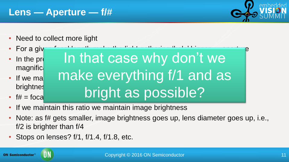
• Need to collect more light
• For a given focal length make the light gathering ‘hole’ bigger — aperture
• In the previous example — we doubled the focal length and doubled the
magnification and reduced the image brightness by four times
• If we make the area four times bigger we would maintain same image
brightness — double the length of one side
• f# = focal length / diameter
• If we maintain this ratio we maintain image brightness
• Note: as f# gets smaller, image brightness goes up, lens diameter goes up, i.e.,
f/2 is brighter than f/4
• Stops on lenses? f/1, f/1.4, f/1.8, etc.
Lens — Aperture — f/#
In that case why don’t we
make everything f/1 and as
bright as possible?
Page 12
Copyright © 2016 ON Semiconductor 12
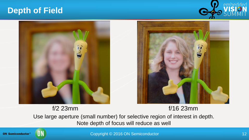
Depth of Field
f/2 23mm f/16 23mm
Use large aperture (small number) for selective region of interest in depth.
Note depth of focus will reduce as well
Page 13
Copyright © 2016 ON Semiconductor 13
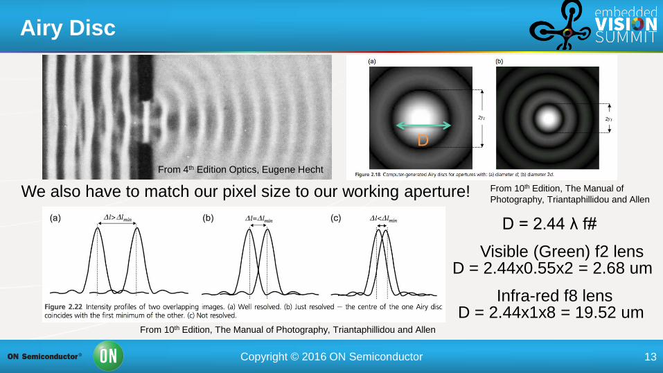
Airy Disc
D = 2.44 λ f#
D
From 10th Edition, The Manual of Photography, Triantaphillidou and Allen
From 10th Edition, The Manual of
Photography, Triantaphillidou and Allen
D = 2.44x0.55x2 = 2.68 um
D = 2.44x1x8 = 19.52 um Infra-red f8 lens
Visible (Green) f2 lens
We also have to match our pixel size to our working aperture!
From 4th Edition Optics, Eugene Hecht
Page 14
Copyright © 2016 ON Semiconductor 14
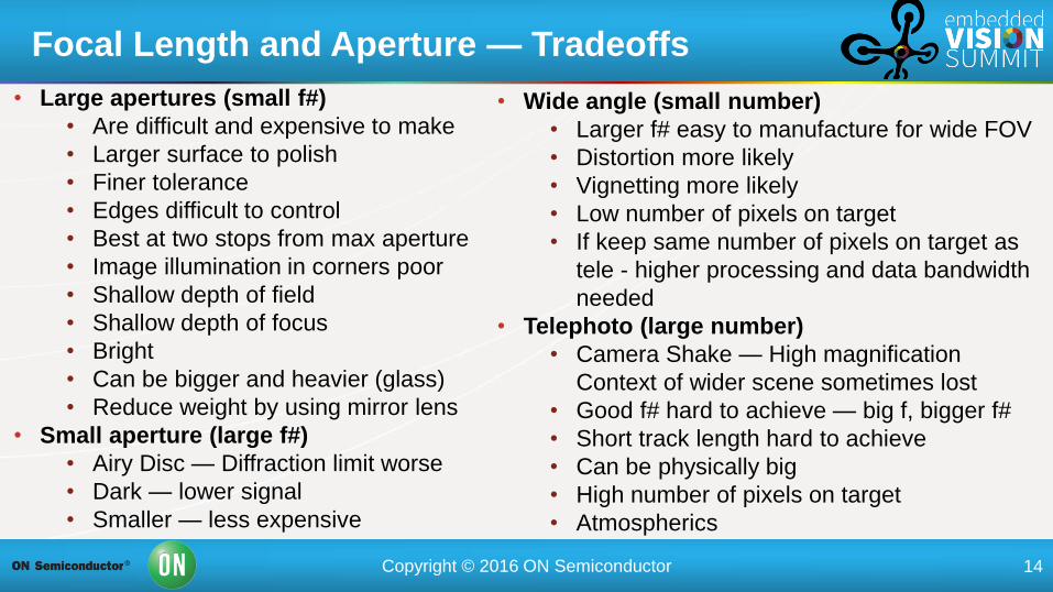
• Large apertures (small f#)
• Are difficult and expensive to make
• Larger surface to polish
• Finer tolerance
• Edges difficult to control
• Best at two stops from max aperture
• Image illumination in corners poor
• Shallow depth of field
• Shallow depth of focus
• Bright
• Can be bigger and heavier (glass)
• Reduce weight by using mirror lens
• Small aperture (large f#)
• Airy Disc — Diffraction limit worse
• Dark — lower signal
• Smaller — less expensive
Focal Length and Aperture — Tradeoffs
• Wide angle (small number)
• Larger f# easy to manufacture for wide FOV
• Distortion more likely
• Vignetting more likely
• Low number of pixels on target
• If keep same number of pixels on target as
tele - higher processing and data bandwidth
needed
• Telephoto (large number)
• Camera Shake — High magnification
Context of wider scene sometimes lost
• Good f# hard to achieve — big f, bigger f#
• Short track length hard to achieve
• Can be physically big
• High number of pixels on target
• Atmospherics
Page 15
Copyright © 2016 ON Semiconductor 15
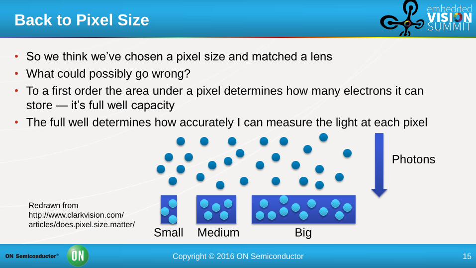
• So we think we’ve chosen a pixel size and matched a lens
• What could possibly go wrong?
• To a first order the area under a pixel determines how many electrons it can
store — it’s full well capacity
• The full well determines how accurately I can measure the light at each pixel
Back to Pixel Size
Photons
Big Small Medium
Redrawn from
http://www.clarkvision.com/
articles/does.pixel.size.matter/
Page 16
Copyright © 2016 ON Semiconductor 16
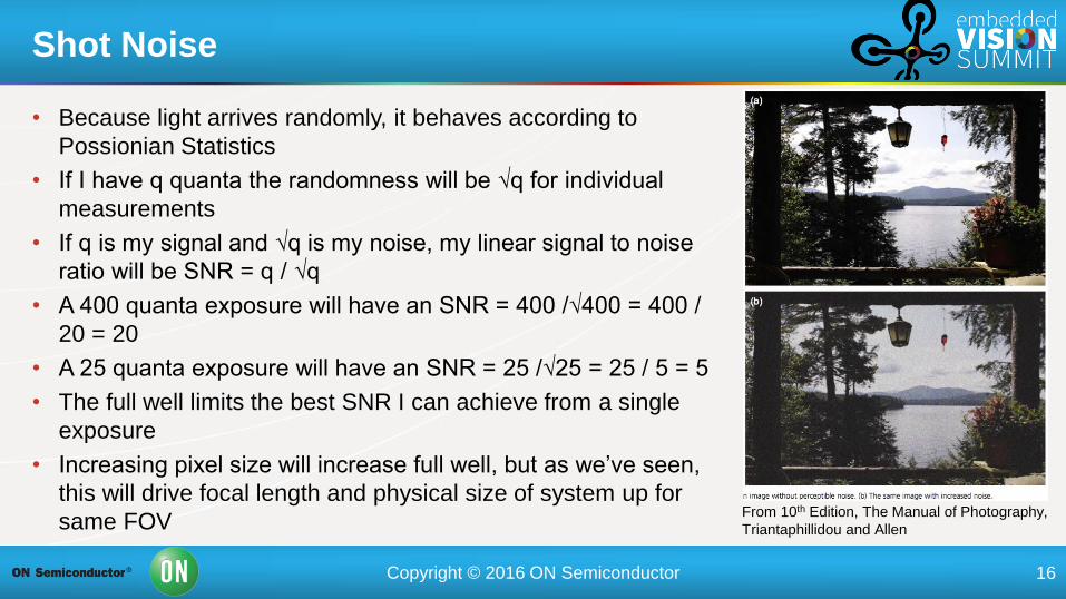
• Because light arrives randomly, it behaves according to
Possionian Statistics
• If I have q quanta the randomness will be √q for individual
measurements
• If q is my signal and √q is my noise, my linear signal to noise
ratio will be SNR = q / √q
• A 400 quanta exposure will have an SNR = 400 /√400 = 400 /
20 = 20
• A 25 quanta exposure will have an SNR = 25 /√25 = 25 / 5 = 5
• The full well limits the best SNR I can achieve from a single
exposure
• Increasing pixel size will increase full well, but as we’ve seen,
this will drive focal length and physical size of system up for
same FOV
Shot Noise
From 10th Edition, The Manual of Photography,
Triantaphillidou and Allen
Page 17
Copyright © 2016 ON Semiconductor 17
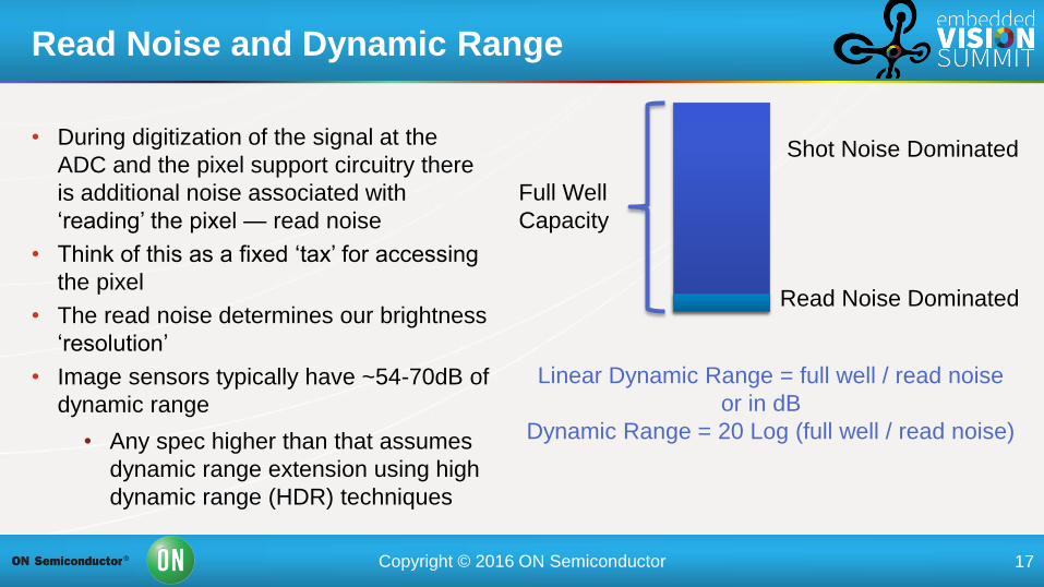
• During digitization of the signal at the
ADC and the pixel support circuitry there
is additional noise associated with
‘reading’ the pixel — read noise
• Think of this as a fixed ‘tax’ for accessing
the pixel
• The read noise determines our brightness
‘resolution’
• Image sensors typically have ~54-70dB of
dynamic range
• Any spec higher than that assumes
dynamic range extension using high
dynamic range (HDR) techniques
Read Noise and Dynamic Range
Full Well
Capacity
Read Noise Dominated
Shot Noise Dominated
Linear Dynamic Range = full well / read noise
or in dB
Dynamic Range = 20 Log (full well / read noise)
Page 18
Copyright © 2016 ON Semiconductor 18
• If you can fill your full well with the brightest parts of the scene without
using gain the exposure will be shot noise dominated
• If you cannot fill your full well and need to use gain, your exposure will be
read noise dominated
• At low light levels read noise is important
• Other sources of noise include dark current — thermally generated
electrons, column and row noise
• If the noise causes a constant deviation or offset of the pixel it is known
as fixed pattern noise (FPN)
• This may influence your choice of using a CCD or CMOS device
Read Noise vs. Shot Noise
Page 19
Copyright © 2016 ON Semiconductor 19
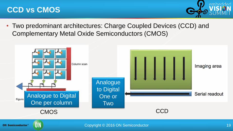
• Two predominant architectures: Charge Coupled Devices (CCD) and
Complementary Metal Oxide Semiconductors (CMOS)
CCD vs CMOS
CMOS CCD
Analogue to Digital
One per column
Analogue
to Digital
One or
Two
Page 20
Copyright © 2016 ON Semiconductor 20
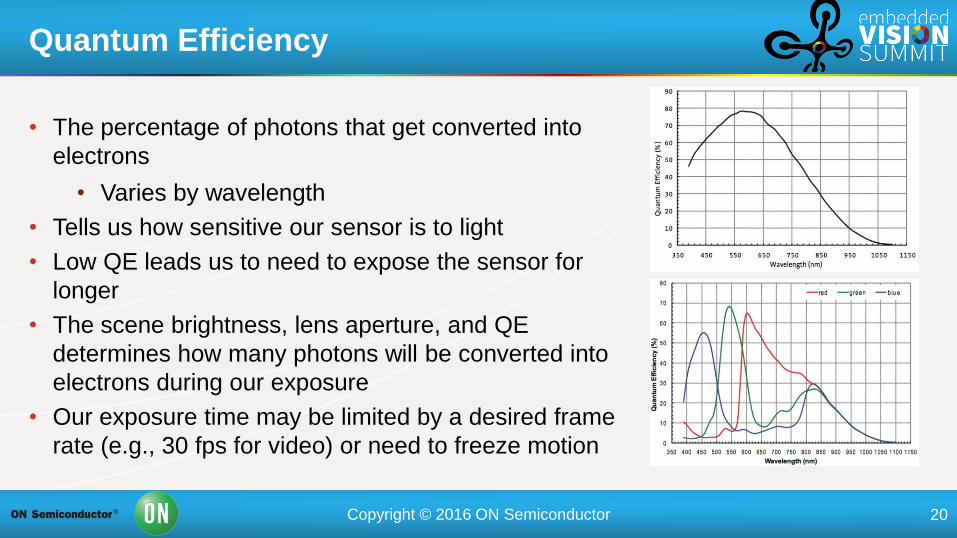
• The percentage of photons that get converted into
electrons
• Varies by wavelength
• Tells us how sensitive our sensor is to light
• Low QE leads us to need to expose the sensor for
longer
• The scene brightness, lens aperture, and QE
determines how many photons will be converted into
electrons during our exposure
• Our exposure time may be limited by a desired frame
rate (e.g., 30 fps for video) or need to freeze motion
Quantum Efficiency
Page 21
Copyright © 2016 ON Semiconductor 21
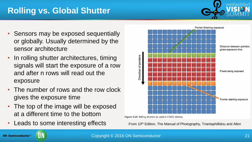
• Sensors may be exposed sequentially
or globally. Usually determined by the
sensor architecture
• In rolling shutter architectures, timing
signals will start the exposure of a row
and after n rows will read out the
exposure
• The number of rows and the row clock
gives the exposure time
• The top of the image will be exposed
at a different time to the bottom
• Leads to some interesting effects
Rolling vs. Global Shutter
From 10th Edition, The Manual of Photography, Triantaphillidou and Allen
Page 22
Copyright © 2016 ON Semiconductor 22
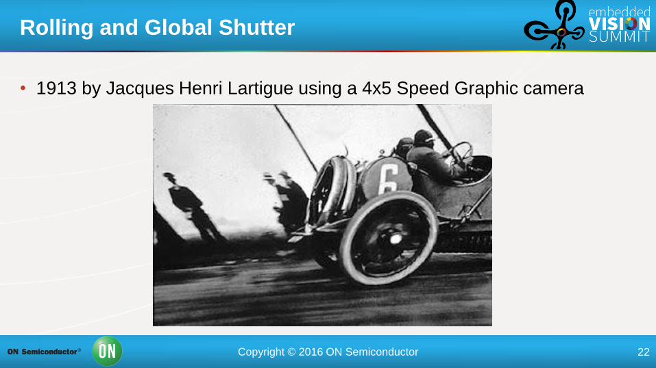
• 1913 by Jacques Henri Lartigue using a 4x5 Speed Graphic camera
Rolling and Global Shutter
Page 23
Copyright © 2016 ON Semiconductor 23
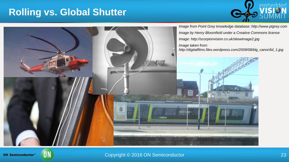
Rolling vs. Global Shutter
Image from Point Grey knowledge database: http://www.ptgrey.com
Image by Henry Bloomfield under a Creative Commons license
Image: http://scorpionvision.co.uk/skewimage2.jpg
Image taken from:
http://digitalfilms.files.wordpress.com/2009/08/blg_canon5d_1.jpg
Page 24
Copyright © 2016 ON Semiconductor 24
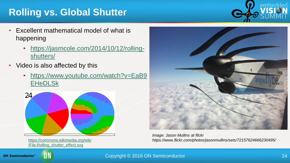
Rolling vs. Global Shutter
Image: Jason Mullins at flickr
https://www.flickr.com/photos/jasonmullins/sets/72157624666230495/ https://commons.wikimedia.org/wiki
/File:Rolling_shutter_effect.svg
• Excellent mathematical model of what is
happening
• https://jasmcole.com/2014/10/12/rolling-
shutters/
• Video is also affected by this
• https://www.youtube.com/watch?v=EaB9
EHeDLSk
Page 25
Copyright © 2016 ON Semiconductor 25
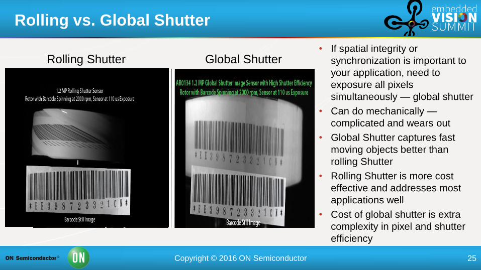
Rolling vs. Global Shutter
Rolling Shutter Global Shutter • If spatial integrity or
synchronization is important to
your application, need to
exposure all pixels
simultaneously — global shutter
• Can do mechanically —
complicated and wears out
• Global Shutter captures fast
moving objects better than
rolling Shutter
• Rolling Shutter is more cost
effective and addresses most
applications well
• Cost of global shutter is extra
complexity in pixel and shutter
efficiency
Page 26
Copyright © 2016 ON Semiconductor 26
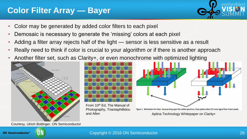
• Color may be generated by added color filters to each pixel
• Demosaic is necessary to generate the ‘missing’ colors at each pixel
• Adding a filter array rejects half of the light — sensor is less sensitive as a result
• Really need to think if color is crucial to your algorithm or if there is another approach
• Another filter set, such as Clarity+, or even monochrome with optimized lighting
Color Filter Array — Bayer
From 10th Ed, The Manual of
Photography, Triantaphillidou
and Allen Aptina Technology Whitepaper on Clarity+
Courtesy, Ulrich Bottinger, ON Semiconductor
Page 27
Copyright © 2016 ON Semiconductor 27
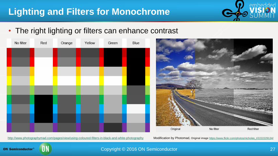
Lighting and Filters for Monochrome
http://www.photographymad.com/pages/view/using-coloured-filters-in-black-and-white-photography Modification by Photomad, Original image https://www.flickr.com/photos/nicholas_t/2222229134/
• The right lighting or filters can enhance contrast
Page 28
Copyright © 2016 ON Semiconductor 28
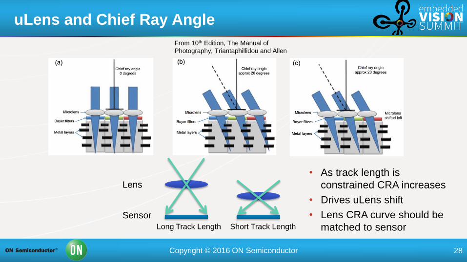
uLens and Chief Ray Angle
From 10th Edition, The Manual of
Photography, Triantaphillidou and Allen
Sensor
Lens
Long Track Length Short Track Length
• As track length is
constrained CRA increases
• Drives uLens shift
• Lens CRA curve should be
matched to sensor
Page 29
Copyright © 2016 ON Semiconductor 29
Typical CRA Curve
Page 30
Copyright © 2016 ON Semiconductor 30
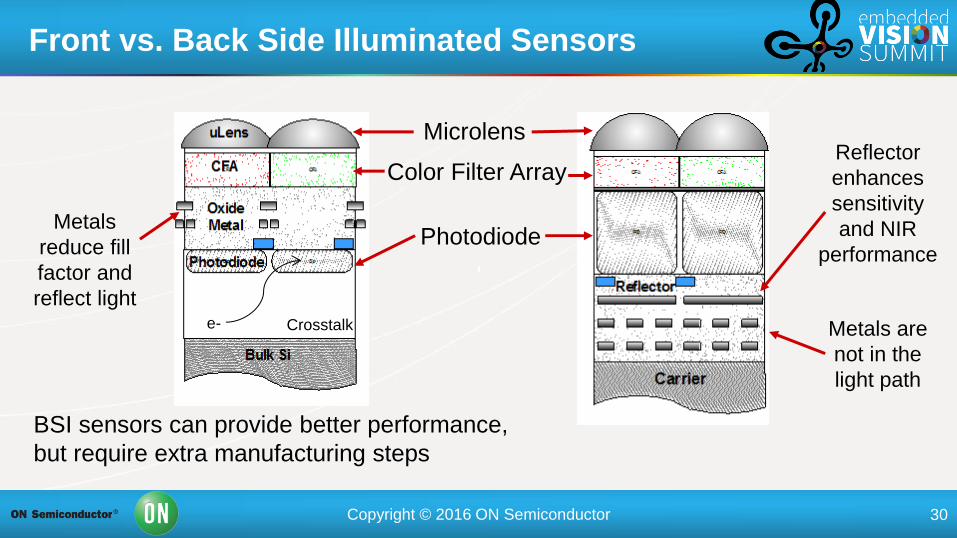
Front vs. Back Side Illuminated Sensors
Microlens
Color Filter Array
Photodiode
Crosstalk e-
Metals
reduce fill
factor and
reflect light
Metals are
not in the
light path
Reflector
enhances
sensitivity
and NIR
performance
BSI sensors can provide better performance,
but require extra manufacturing steps
Page 31
Copyright © 2016 ON Semiconductor 31
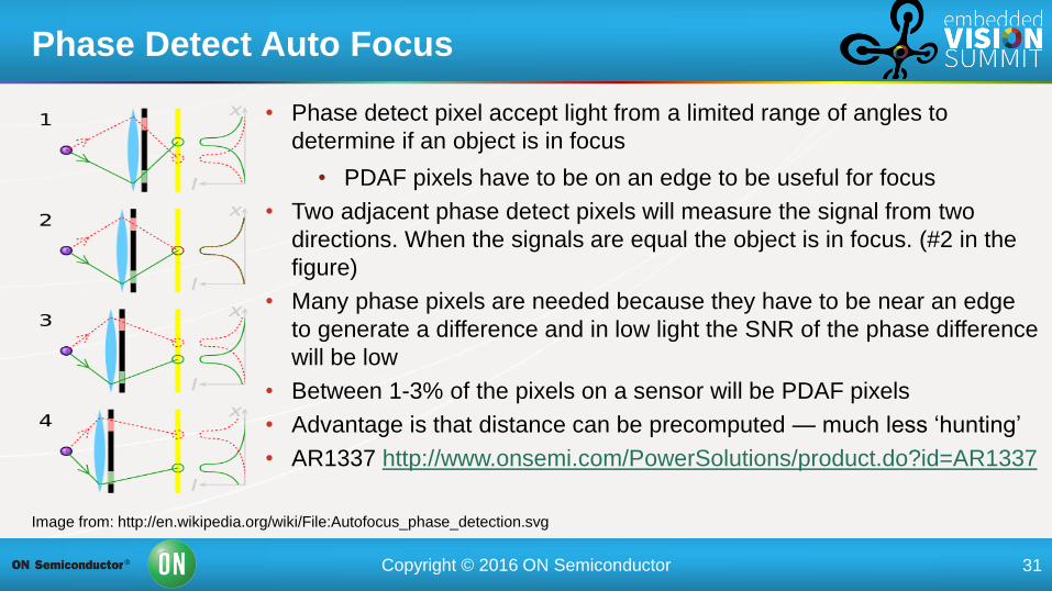
• Phase detect pixel accept light from a limited range of angles to
determine if an object is in focus
• PDAF pixels have to be on an edge to be useful for focus
• Two adjacent phase detect pixels will measure the signal from two
directions. When the signals are equal the object is in focus. (#2 in the
figure)
• Many phase pixels are needed because they have to be near an edge
to generate a difference and in low light the SNR of the phase difference
will be low
• Between 1-3% of the pixels on a sensor will be PDAF pixels
• Advantage is that distance can be precomputed — much less ‘hunting’
• AR1337 http://www.onsemi.com/PowerSolutions/product.do?id=AR1337
Phase Detect Auto Focus
Image from: http://en.wikipedia.org/wiki/File:Autofocus_phase_detection.svg
Page 32
Copyright © 2016 ON Semiconductor 32
• General industrial trend to smaller pixels, higher resolution and speed and CMOS
• High speed driving need to get data stream from camera and configurations
• Increasing focus on price and power dissipation
• Machine vision cameras <1” most new camera platforms standardizing on a 29 x 29 mm
casing, generating the necessary power and thermal challenges
• CCD remains popular at high resolutions
• Expect that for scientific and medical applications CCD is likely to be the preferred choice
for the foreseeable future
• CMOS size, price and speed are very attractive and optical performance is great for many
applications, e.g., ADAS
• Scientific and medical applications CCD is likely to be the preferred choice for the
foreseeable future
Some Observations
Page 33
Copyright © 2016 ON Semiconductor 33
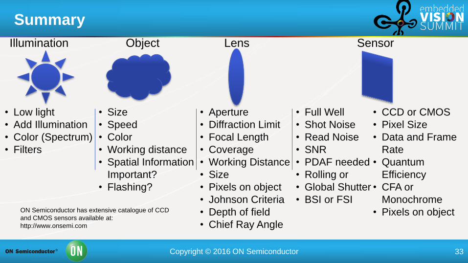
Summary
• CCD or CMOS
• Pixel Size
• Data and Frame
Rate
• Quantum
Efficiency
• CFA or
Monochrome
• Pixels on object
• Aperture
• Diffraction Limit
• Focal Length
• Coverage
• Working Distance
• Size
• Pixels on object
• Johnson Criteria
• Depth of field
• Chief Ray Angle
• Low light
• Add Illumination
• Color (Spectrum)
• Filters
• Size
• Speed
• Color
• Working distance
• Spatial Information
Important?
• Flashing?
ON Semiconductor has extensive catalogue of CCD
and CMOS sensors available at:
http://www.onsemi.com
Illumination Lens Sensor Object
• Full Well
• Shot Noise
• Read Noise
• SNR
• PDAF needed
• Rolling or
• Global Shutter
• BSI or FSI
Page 34
Copyright © 2016 ON Semiconductor 34
Thanks
Robin Jenkin
ON Semiconductor
[email protected]
www.onsemi.com