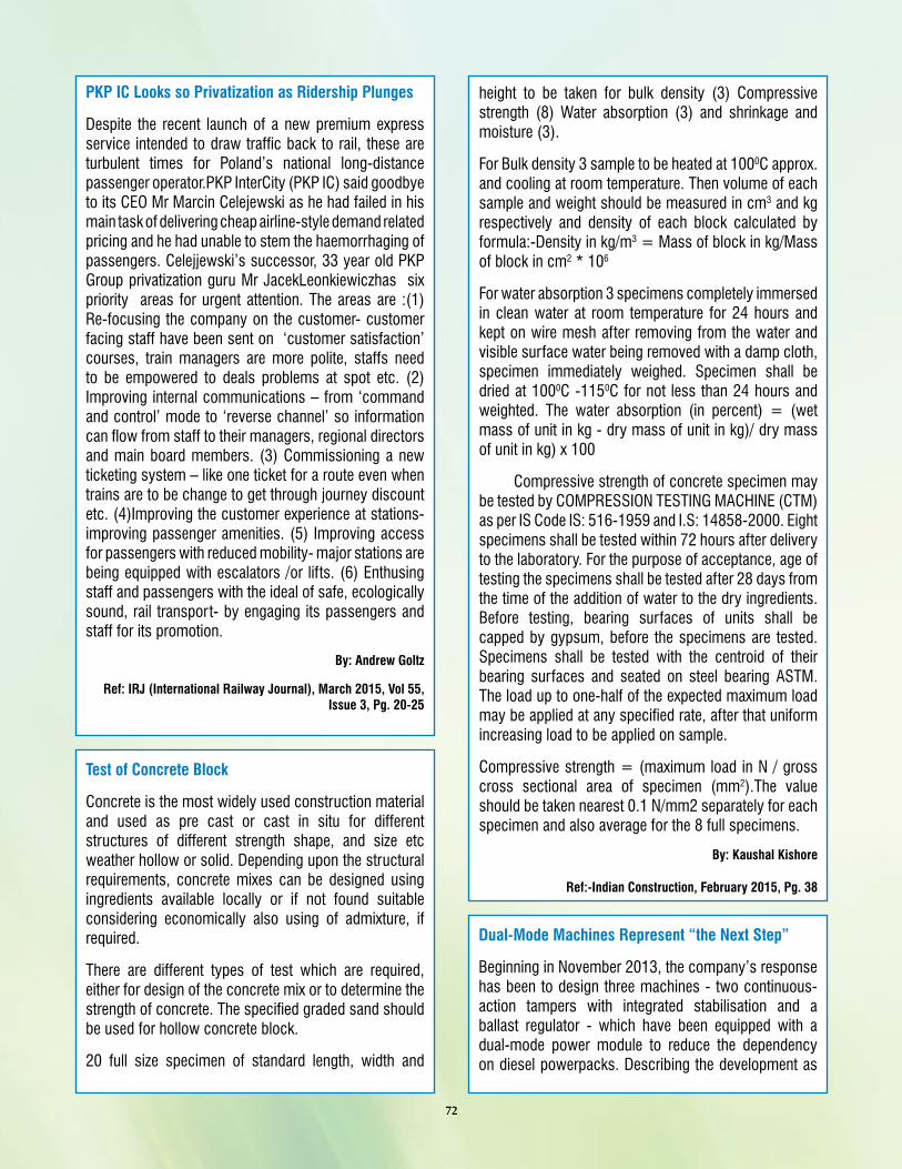
IRICEN Journal of Civil Engineering Volume 8, No. 4 www.iricen.indianrailways.gov.in Indian Railways Institute of Civil Engineering, Pune October - December 2015 I R I C E N D A Y 2 0 1 5 U n v e l i n g o f I R I C E N ’ s P u b l i c a t i o n s Chief Guest with Awardees Best Probationer Award to Mrs. Mansi Mittal
Transcript
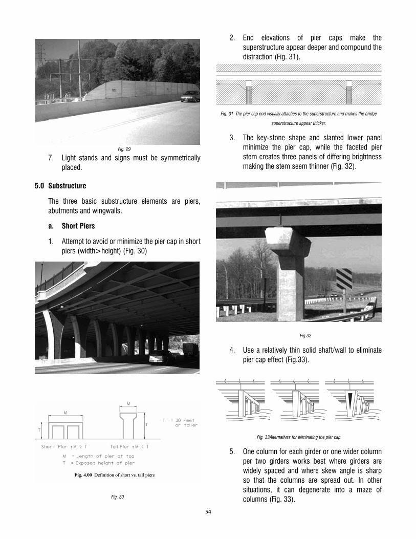
IRICEN Journal of
Civil Engineering
Volume 8, No. 4 www.iricen.indianrailways.gov.in
Indian Railways Institute of Civil Engineering, Pune
October - December 2015
I R I C E N D A Y 2 0 1 5
U n v e l i n g o f I R I C E N ’ s P u b l i c a t i o n s
Chief Guest with Awardees Best Probationer Award to Mrs. Mansi Mittal
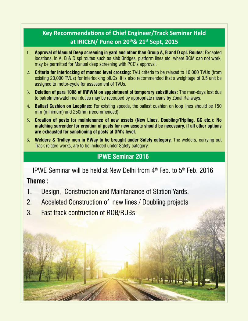
IPWE Seminar 2016
IPWE Seminar will be held at New Delhi from 4th Feb. to 5th Feb. 2016
Theme :
1. Design, Construction and Maintanance of Station Yards.
2. Acceleted Construction of new lines / Doubling projects
3. Fast track contruction of ROB/RUBs
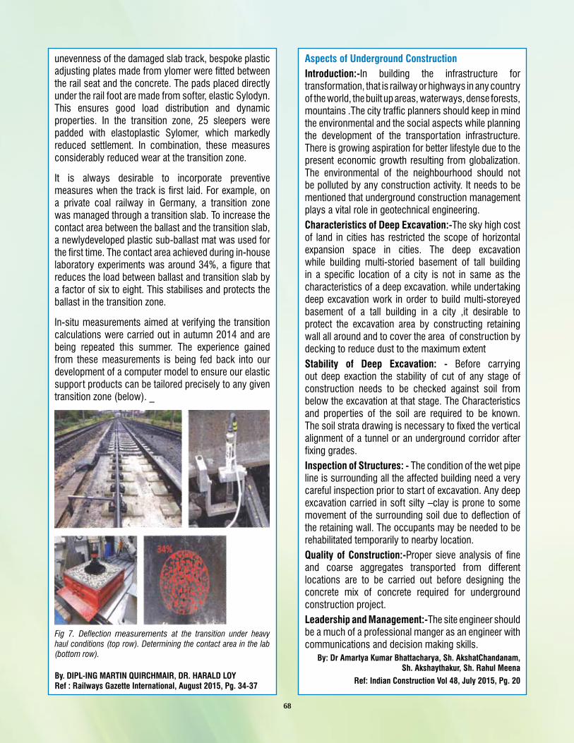
Key Recommendations of Chief Engineer/Track Seminar Held at IRICEN/ Pune on 20th& 21st Sept, 2015
1. Approval of Manual Deep screening in yard and other than Group A, B and D spl. Routes: Excepted locations, in A, B & D spl routes such as slab Bridges, platform lines etc. where BCM can not work, may be permitted for Manual deep screening with PCE’s approval.
2. Criteria for interlocking of manned level crossing: TVU criteria to be relaxed to 10,000 TVUs (from existing 20,000 TVUs) for interlocking ofLCs. It is also recommended that a weightage of 0.5 unit be assigned to motor-cycle for assessment of TVUs.
3. Deletion of para 1008 of IRPWM on appointment of temporary substitutes: The man-days lost due to patrolmen/watchmen duties may be recouped by appropriate means by Zonal Railways.
4. Ballast Cushion on Looplines: For existing speeds, the ballast cushion on loop lines should be 150 mm (minimum) and 250mm (recommended).
5. Creation of posts for maintenance of new assets (New Lines, Doubling/Tripling, GC etc.): No matching surrender for creation of posts for new assets should be necessary, if all other options are exhausted for sanctioning of posts at GM’s level.
6. Welders & Trolley men in P.Way to be brought under Safety category. The welders, carrying out Track related works, are to be included under Safety category.
1
From director’s desk
Dear Readers,
The last quarter of 2015 had been quite reminiscing, when IRICEN Day was
celebrated with a huge enthusiasm and fervour. The meritorious IRSE Probationers
and other trainee officers were awarded with trophies/medals/shields for their
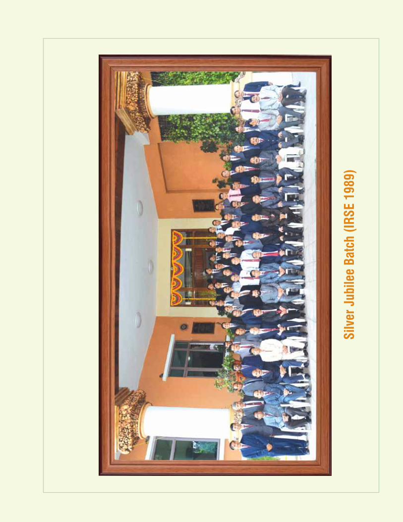
outstanding performance during the previous year. The 1989 exam batch IRSE
officers, having completed 25 years (Silver Jubilee Batch) were also felicitated
with mementos for their unrelenting service and contribution to Indian Railways.
This edition of IRICEN Journal includes papers on wide ranging topics. The
understanding of new features of arbitration and conciliation amendment Act
2015 is essential for all persons dealing with arbitration cases as arbitrators,
respondents or in any other capacities to ensure that there are no lacunae in the
process. Another paper on aesthetics indicates that contrary to popular notion,
aesthetically better looking and well designed structures and bridges offers not
only a pleasant sight but it may also be economical in terms of design without
compromising on functionalities.
On the Indian Railway system lot of innovative methods and practices and
specialised works are undertaken on regular basis which are also getting reported
in various forums etc. PCEs / CAO(C)s are requested that the contributions to
IRICEN Journal in the form of technical papers, articles, news etc be sent on
regular basis for publication in the Journal for wider publicity and application.
1. Salient Feature of Arbitration & Conciliation (Amendment) Act, 2015 09 Shri. Anil Kumar, CE/CN/S.Rly. 2. Evolution of Locomotives on Indian Railways 13 Shri. S.K.Bansal, Sr. Prof/Project/IRICEN, Shri. R.A.Sayyad, SI/Mech-II
3. Long Life Painting Scheme for Cable Stayed ROB at Barddhaman 19 Shri. Harsimran Singh, DGM(G), SE Railway 4. Concepts of Design & Construction of Various Track Structures in 23 Chennai Metro Systems Shri. Suriyamoorthy.V, ADEN/VM/SR, Miss. Praveena. M, ADEN/TJ/SR
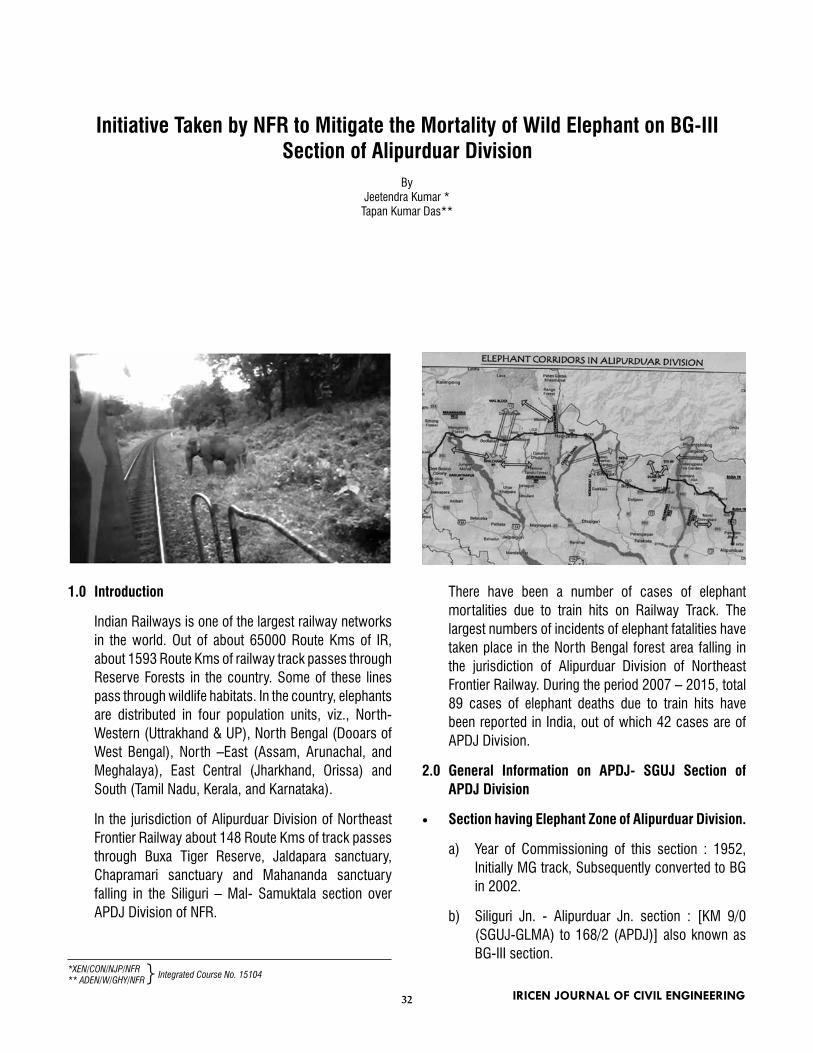
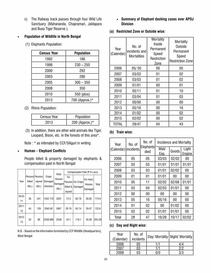
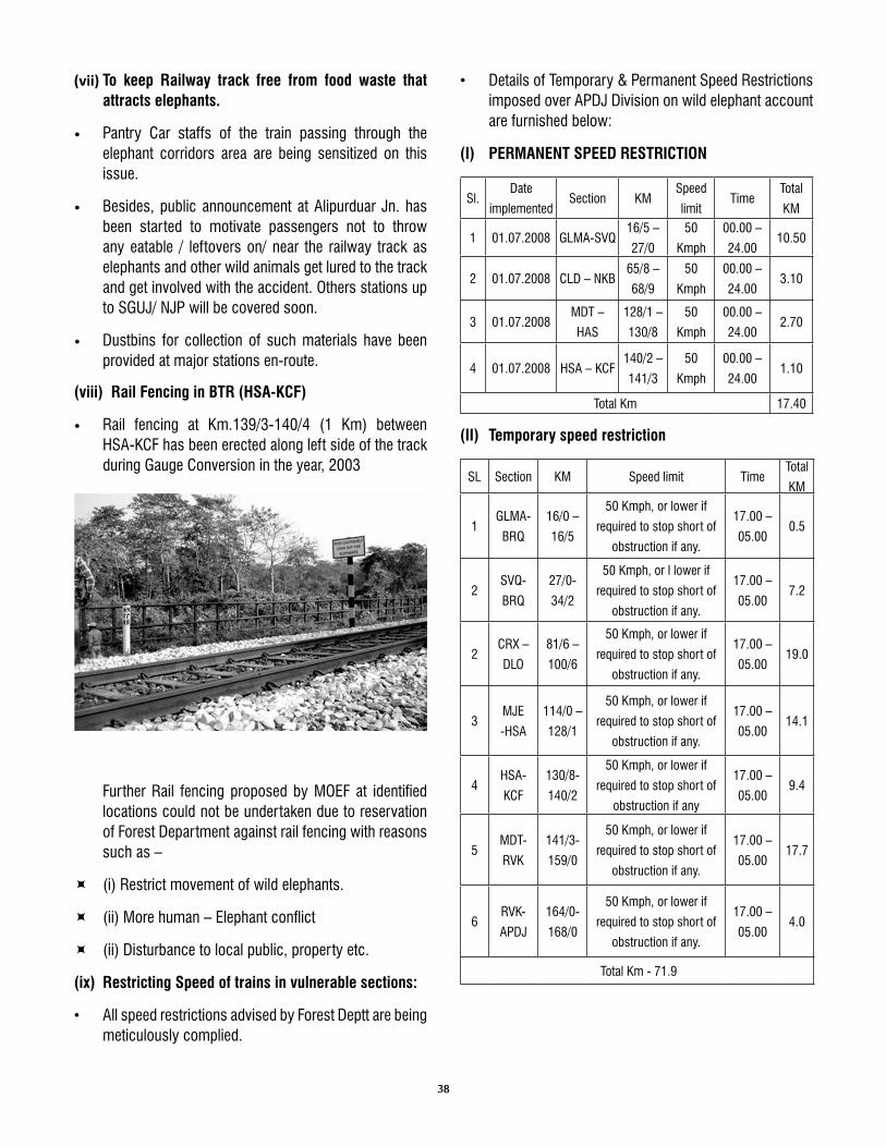
5. Initiative Taken by NFR to Mitigate the Mortality of Wild Elephant on 32 BG-III Section of Alipurduar Division Shri. Jeetendra Kumar, XEN/CON/NJP/NFR, Shri. Tapan Kumar Das , ADEN/W/GHY/NFR
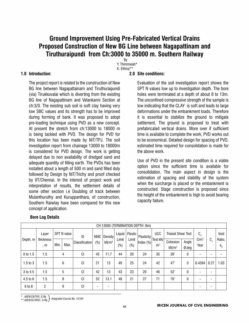
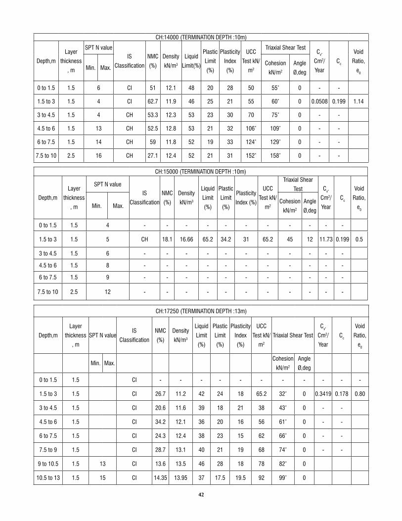
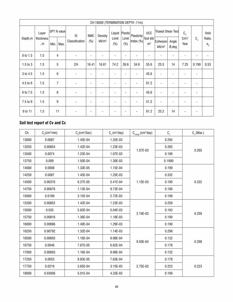
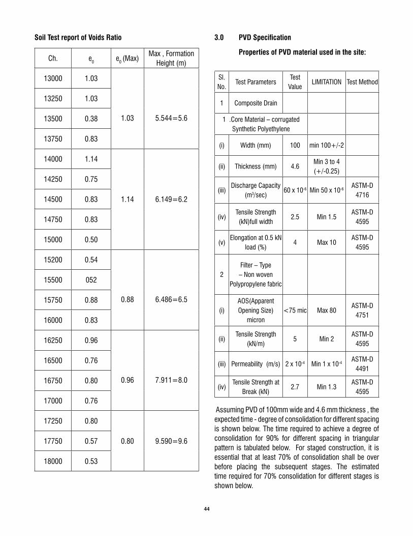
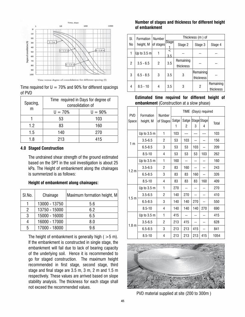
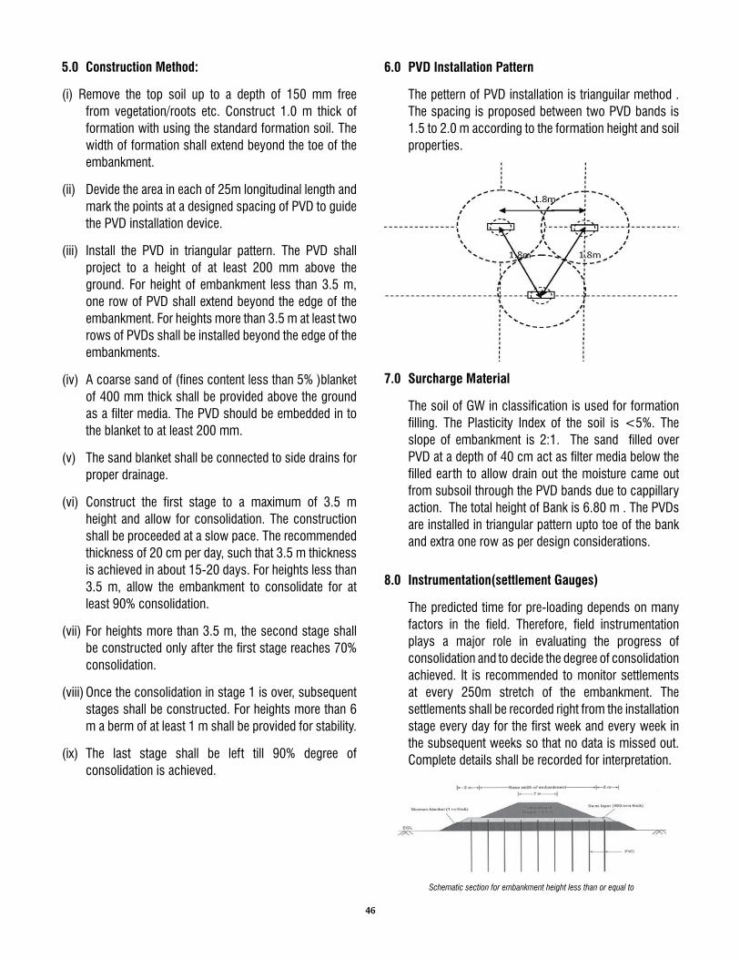
6. Ground Improvement Using Pre-Fabricated Vertical Drains Proposed 41 Construction of New BG Line between Nagapattinam and Tiruthuraipundi from Ch:3000 to 35000 m. Southern Railway Shri. Y. Thimmaiah, AXEN/CN/TVR, S.Rly, Shri. K. Ethiraj, AXEN/GC/MSC, S.Rly.
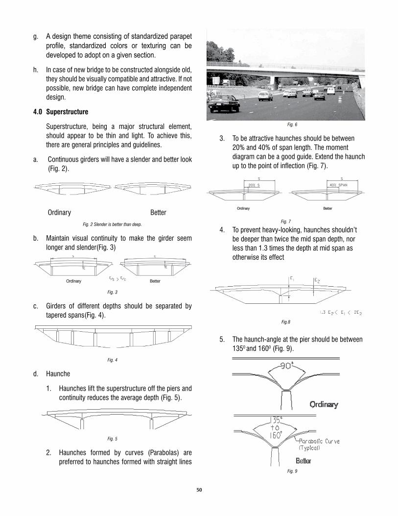
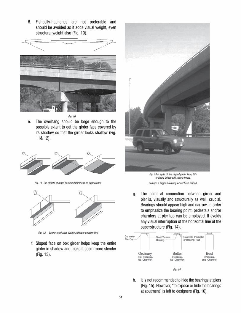
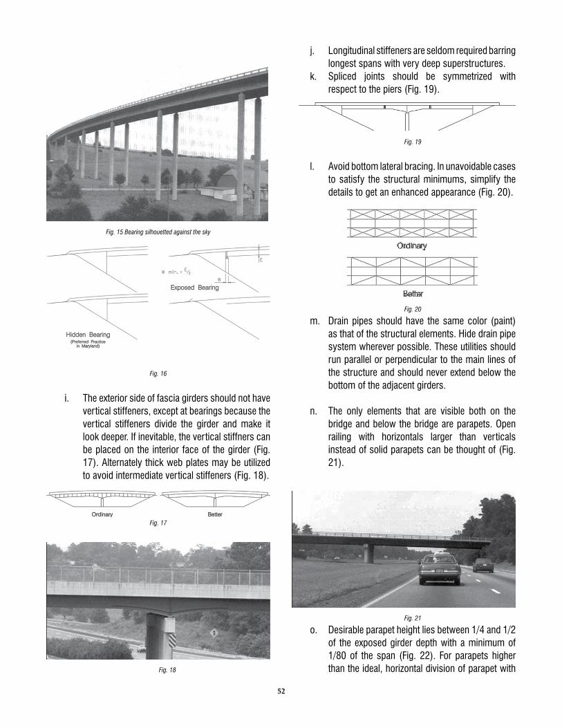
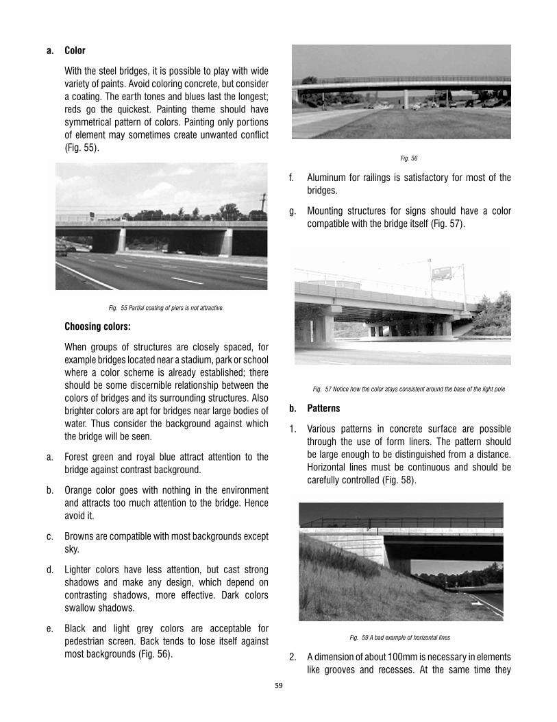
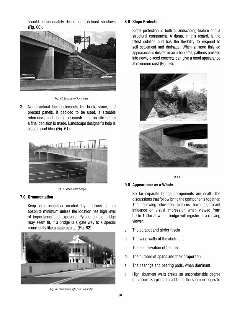
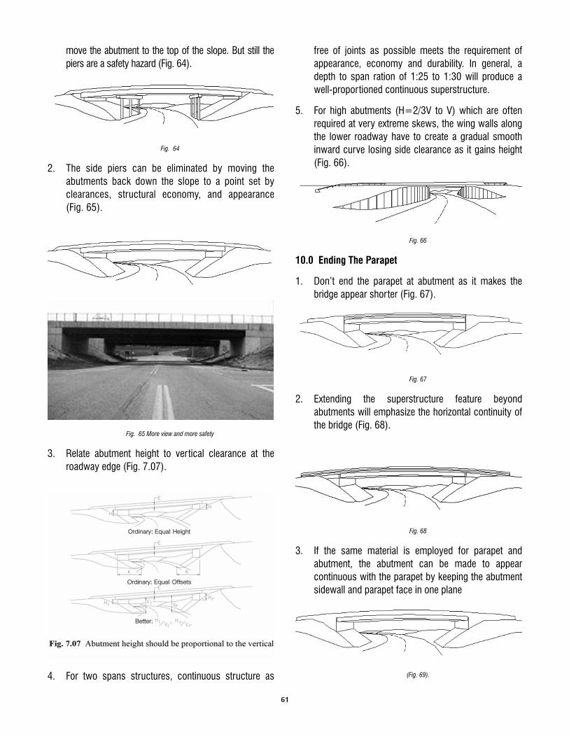
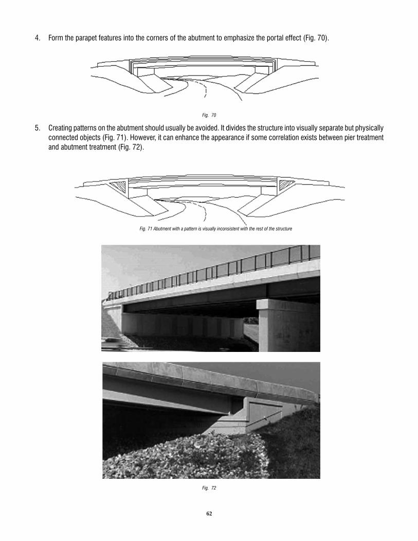
7. Aesthetics in Bridges 49 Shri. B. Rama Rao, ADEN/Kadapa/SCR
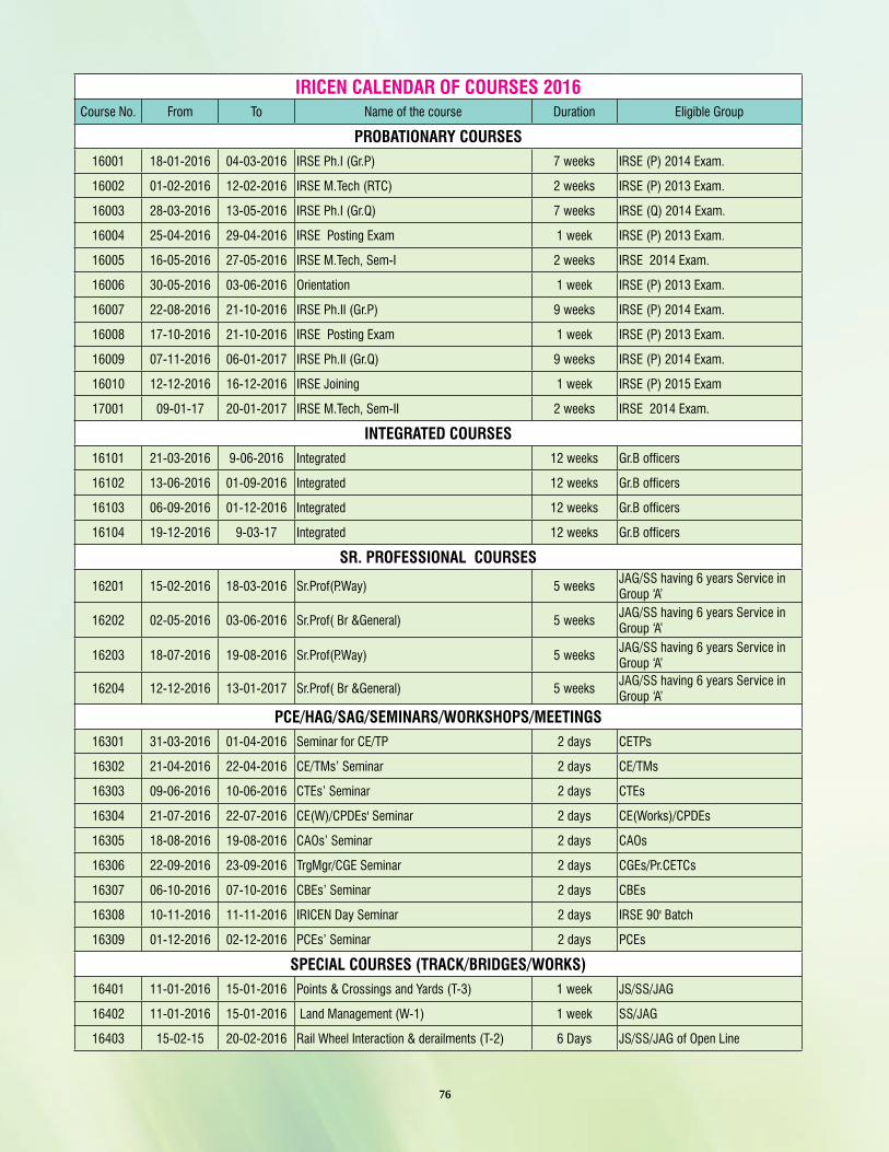
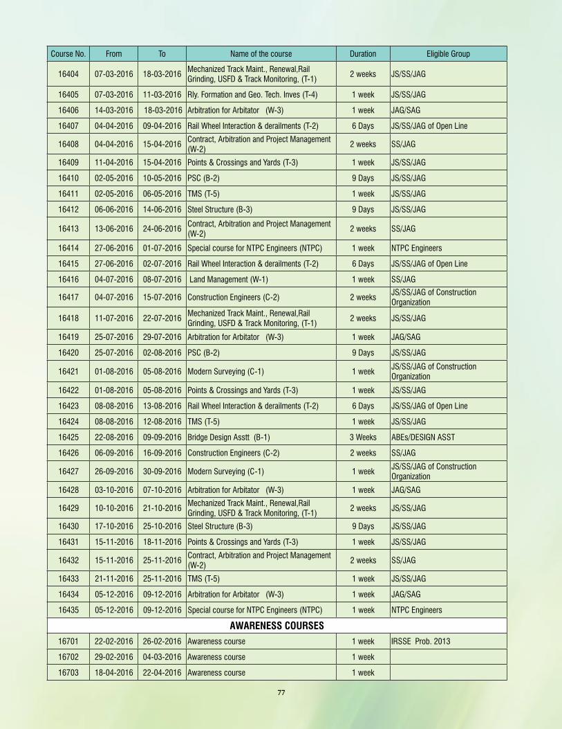
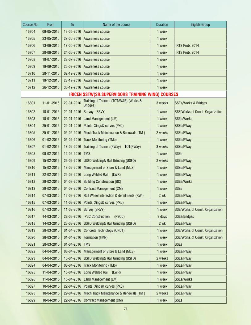
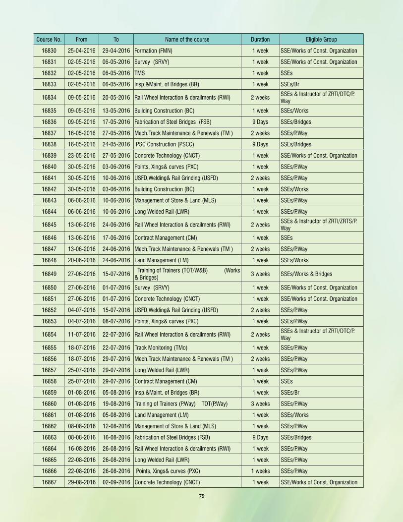
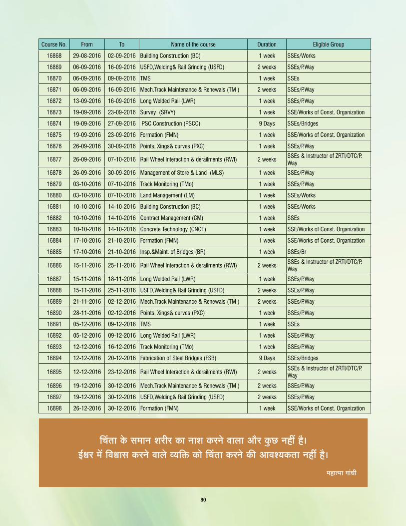
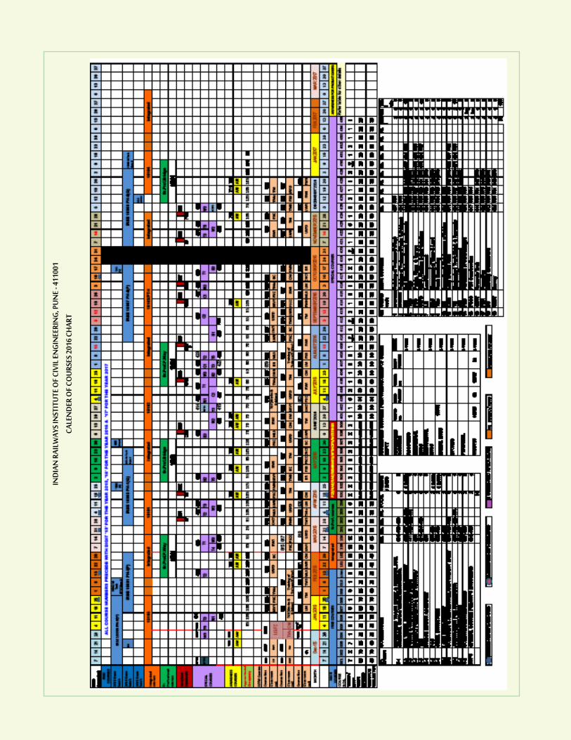
IV) Literature Digest 65V) Calendar of Courses 76
Suggestion for improvement of IRICEN JOURNAL OF CIVIL ENGINEERING are welcome from the readers. Suggestions may be sent to [email protected]
Guidelines to contributorsArticles on the Railway Civil Engineering are welcome from the authors. The authors who are willing to contribute articles in the IRICEN Journal of Civil Engineering are requested to please go through the following guidelines :
1. The paper may be a review of conventional technology, possibilities of improvement in the technology or any other item which may be of interest to the readers. The paper should be reasonably detailed so that it could help the reader to understand the topic. The paper may contain analysis, design, construction, maintenance of railway civil engineering assets. The paper should be concise.
2. The journal is likely to be printed in a paper of size 215 mm X 280 mm. While sending the articles the author should write in 2 columns. Sketches, tables and figures should be accom-modated in a 2 column set up only.
3. Author should send the original printout of photograph along with the digital copy of the photograph.
4. Soft copy as well as hard copy of article must be invariably sent to the editors of concerned subject.
5. Only selected articles will be included in the IRICEN Journal of Civil Engineering.
IndexEDITORIAL BOARD
EDITING TEAM
TRACK
WORKS
BRIDGES
EDITORIAL ASSISTANCE
Shri Vishwesh ChaubeyDirector/IRICENChairman
Shri N. C. ShardaDean
Shri C. S. SharmaSr. Professor TrackExecutive Editor
Shri A. K. PatelProfessor - Track IShri M. B. DekateProfessor - Track MachineShri Suresh PakhareProfessor - Track IIShri N. K. MishraAssociate Professor - Track IShri J. M. PatekariAsst. Professor - Track IShri R. K. KathalAsst. Professor - Track IIShri R. P. SinghAsst. Professor - Track III
Shri R. P. Saxena Sr. Professor EngineeringShri S. K. BansalSr. Professor ProjectsShri S. K. GargSr. Professor WorksShri Gautam BirhadeProfessor WorksShri Neeraj KhareProfessor/Est.Shri N. R. KaleAsst. Professor - Works
Shri Ramesh PinjaniSr. Professor Bridge - IIShri Vineet GuptaSr. Professor Bridge - IShri. Sharad Kumar AgarwalProfessor Bridge
The papers & articles express the opin-ions of the authors, and do not neces-sarily reflect the views of IRICEN editorial panel. The institute is not responsible for the statements or opinions expressed in its publication.
Shri Pravin KotkarSr. Instructor - Track I
3
Railways to Attract $20 Bn for Station Development
At the CII function in Delhi the Railway Minister, Suresh Prabhu, said that the proposed station development project will attract about $20 billion in phases. He said discussions are being held with World Bank for creating a fund of $30 billion to fund key rail infrastructure projects. According to him railways has undertaken an ambitious scheme for development of 400 stations across the country. Railways plan to develop 400 stations in a unique model with an expected investment of 20 billion US dollar. He said that tenders will be invited with highest level of transparency. The minister said that there are many ongoing projects like DFC, gauge conversation, doubling, safety upgradation which involves good investments. LIC has signed an MoU with railways committing investment of ` 1.5 lakh crore in the next five years. On ties with other countries, Prabhu said there will be collaboration with Japan and Korea for carrying out research on railways. He further said that waterless and odourless toilets will be developed in collaboration with RDSO and Japan.
Ref : The Masterbuilder, October 2015
CMRL Uses Wireless Tech for Perfect Track Alignment
In an attempt to achieve perfect alignment of tracks, Chennai metro rail has adopted wireless technology from a US-based company, Trimble that set alignment for bullet train tracks in China. Working in association with Larsen and Toubro, a small team from Trimble, which has an R&D unit in Chennai, uses equipment that can scan alignment of tracks after they are laid and upload information wirelessly on to the system. It saves time, cost and eliminates human error. Conventionally, staff on a trolley pushed along the tracks check for alignment. Chennai Metro Rail Ltd (CMRL) contractors have brought in the latest technology as the tracks are on elevated lines and in tunnels. Trimble Managing Director (SAARC Region), Rajan Aiyer, said that the technology was also used to check alignment for tracks used for high speed trains where a slight change in alignment could have huge consequences. It was used for track alignment at Bengaluru and Hyderabad Metro Rail systems.
Ref : The Masterbuilder, October 2015
Committee Under NITI Aayog Takes Over Appraisal Process of High-Speed Railway Network
The PMO-appointed Empowered Committee on Innovative Collaborations under NITI Aayog Vice-Chairman, Arvind Panagariya has taken over the appraisal of the ambitious High-speed Railway network to ascertain its way forward and how to go about implementing the first section between Mumbai and Ahmedabad. The high-power committee also has secretaries of Department of Economic Affairs and Department of Industrial Policy and Promotion. The committee reviewed a presentation from Railway Board on the latest Japan International Cooperation Agency report on the Mumbai-Ahmedabad high-speed corridor and an overview of the other lines. The first high-speed link, whose final report by Japan was submitted in July, has been lying in Railway Board’s perusal process. The committee stepping in to appraise and prescribe a way forward for the project also relieves the Railway Board of the tough task of having to take a decision of this magnitude the first corridor will cost around ` 98,000 crore and places the project in a higher league, sources said. As per the mandate of the committee, its recommendations cannot be overruled by the ministry. In case a ministry does not agree with the recommendations, the matter will go to the Cabinet.
Ref : The Masterbuilder, November 2015
Rail Line Projects Worth ` 8351 Cr Cleared
The Centre has cleared four rail line projects in Odisha, Andhra Pradesh and Chhattisgarh at a cost of around
` 8351 crore. Government gave its approval for the doubling of 189.278 km Kottavalasa-Koraput railway line with a completion cost of ` 2977.64 crore. It also approved doubling of 164.56 km Koraput-Singapur Road section railway line with a completion cost of ` 2361.74 crore and 110.22 km Jagdalpur-Koraput section railway line with a completion cost of `1839.02 crore. The demand of goods traffic on these existing single lines was increasing over a period due to increase of production of goods and minerals in the vast catchment and subsequent transportation requirement. These projects are likely to be completed in the next seven years during 12th and 13th Plan period. Besides, the Union Cabinet also gave its approval for third and fourth lines between Budhapank and Salegaon via Rajathgarh railway line. This 85 km long stretch will cost a sum of ` 1172.92 crore. The project is likely to be completed in the next three years. The existing line is catering to the originating traffic from Mahanadi Coal Fields to the Paradip and Vishakhapatnam ports.
Ref : The Masterbuilder, November 2015
Railway News
4
Railways to Spend ` 82,000 Crore in Capex
The Indian Railways is on a major capital expenditure (Capex) drive with ` 82,000 crore worth of orders being placed, Railway Minister, Suresh Prabhu said at 95th Annual Session of ASSOCHAM held in New Delhi. Railway is taking a slew of steps to upgrade customer service including clean stations, e-catering and improved services. The capex spend would include a ` 40,000 crore order with the GE. Indian Railways upgrade to boost Economic Growth by 3%, says Suresh Prabhu. He added that projects were being awarded in a transparent manner. Funds were raised at an affordable rate from the LIC which is just above the government security (G-Sec) rate paid in 30 years. The ministry is also discussing the creation of a $30 billion fund with the World Bank to finance key rail projects, he said, further adding that the capex plans included ` 82,000 crore for a Dedicated Freight Corridor project. The Minister also said that capital expenditure of ` one lakh crore on building new infrastructure would be spent within the current financial year in the most transparent manner. As for structural reforms, the Indian Railways, Prabhu said, is trying to frame a regulatory system, Mr. Prabhu said. He said if things go as planned for the capex spend and boosting the Indian Railways activity, this alone could contribute between two and 2.5 per cent to the country’s GDP.
Ref : The Masterbuilder, November 2015
Japan Offers to Finance India’s $15bn Bullet Train Project
Japan has offered to finance India’s first bullet train, estimated to cost $15 billion, at an interest rate of less than 1 percent, stealing a march on China, which is bidding for other projects on Indian rail network. Tokyo was picked to assess the feasibility of building the 505-kilometre corridor linking Mumbai with Ahmedabad and concluded it would be technically and financially viable. The project to build and supply the route will be put out to tender, but offering finance makes Japan the clear frontrunner. Last month China won the contract to assess the feasibility of a high-speed train between Delhi and Mumbai, a 1,200-km route estimated to cost twice as much. No loan has yet been offered. Japan has recently lost to China in bidding to build Indonesia’s first high-speed railway
Ref : The Masterbuilder, November 2015
Railways to Co-Operate with German Companies in Modernization, Redevelopment Plan
India agreed to open up commercial opportunities for German companies in the high-speed rail segment and station redevelopment plans. The move is part of attracting foreign investment in the modernization and expansion plan of the Indian railways. A joint declaration on the further development of the cooperation in the field of railways between Germany’s Transport and Digital Infrastructure Ministry and Railway Ministry shows that both sides will enhance bilateral cooperation in the rail sector. India’s railway modernization and expansion plans open up commercial opportunities for German companies in high-speed rail, station redevelopment, rolling stock manufacturing and logistics terminals. Both countries urged the private players to explore early participation in this sector. Railways have offered massive investment opportunities at the proposed Diamond Quadrilateral project aiming to connect all four metro cities with high speed rail network. It has also offered private investment in the redevelopment of about 400 stations across the country. The joint declaration reveals that training managers, supervisors and instructors from Indian Railways is another potential area of collaboration between both the countries.
Ref : The Masterbuilder, October 2015
India Ranks Third Among Top 10 Countries for LEED Green Buildings
Japan has offered to finance India’s first bullet train, estimated to cost $15 billion, at an interest rate of less than 1 percent, stealing a march on China, which is bidding for other projects on Indian rail network. Tokyo was picked to assess the feasibility of building the 505-kilometre corridor linking Mumbai with Ahmedabad and concluded it would be technically and financially viable. The project to build and supply the route will be put out to tender, but offering finance makes Japan the clear frontrunner. Last month China won the contract to assess the feasibility of a high-speed train between Delhi and Mumbai, a 1,200-km route estimated to cost twice as much. No loan has yet been offered. Japan has recently lost to China in bidding to build Indonesia’s first high-speed railway
Twelve New Railway Lines Being Constructed in the Northeast
Work on 12 new railway lines with a total length of 1,248 km is being taken up in the North east.
“Against a national average of 20 km per 1,000 sq km railway network density, the northeastern states have an average railway network density of 10.1 km per 1,000 sq km.” Minister of State for Railways Manoj Sinha said in a written reply to the Lok Sabha.
“Twelve new line works have been taken up in northeastern region having a total length of 1, 248km AT A TOTAL COST OF Rs.38,416 crore (Rs.384 billion),” he said.
According to the minister, Rs.2,279 crore was allocated in 2012-13, Rs.3,392 crore in 2013-14 and Rs.5,200 crore in 2014-15 for new lines, gauge conversion and doubling the existing lines in the region.
“An increased outlay of Rs. 5,338 crore has been provided in 2015-16 for speedier execution of projects in the northeastern region,” Sinha said.
The Euro 384 million, Spain-based Talgo, the manufacturer of intercity, high speed and passenger trains has suggested using the legacy network of the Indian railways to providefaster connectivity. What Talgo plans to do is launch its lighter, faster trains in India for which it has an in-principle nod. If all goes well, the first of these light, fast train sets would be imported to India by the end of the year. The immediate impact will be a reduction in the travel time berween Delhi and Mumbai by 30% to 12 hrs.
The Talgo trains travel at speeds of 160 – 220 kilometers per hour, much higher than the current high of 130 kilometres per hour. Though they are slower than the 350 kilometres per hour achieved by high speed trains like japan’s Shinkansen or France’s TGV, the invesetment too is much lower. With the government opening up investment in the sector, Talgo is open to setting up a plant to make the trains here.
In an attempt to effectively check the rampant rate of accidents on railway crossing across the country, the Indian Railways has decided to construct as many as 12,330 rail over bridges (ROBs) as most of accidents normally occurs on these unmanned railway crossings. Minister of State for Railways Manoj Sinha said in a recent statement, shortly after laying the foundation stone of railway bridge on jaunpur-Mirzapur route.
Quoting available stats, he went on adding that 40% accidents took place while vehicles pass through unmanned crossing, and 60% lives lost due to such incidents. The cost of the construction of these bridges would be shared by the Indian Railways and the National Highway Authority of India in 50:50 ratio. All these projects are being executed on the fast tracked basis, he added.
Ref : New Building Materials & Construction World, September 2015, Pg. 20
India Plans `5 bn Bridge Across Meghna River
In an attempt to effectively check the rampant rate of accidents on railway crossing across the country, the Indian Railways has decided to construct as many as 12,330 rail over bridges (ROBs) as most of accidents normally occurs on these unmanned railway crossings. Minister of State for Railways Manoj Sinha said in a recent statement, shortly after laying the foundation stone of railway bridge on jaunpur-Mirzapur route.
Quoting available stats, he went on adding that 40% accidents took place while vehicles pass through unmanned crossing, and 60% lives lost due to such incidents. The cost of the construction of these bridges would be shared by the Indian Railways and the National Highway Authority of India in 50:50 ratio. All these projects are being executed on the fast tracked basis, he added.
Ref : New Building Materials & Construction World, September 2015, Pg. 24
Swiss Challange Method for NHs.
The government is seriously considering adoption of Swiss challenge method for private players to develop highways in the country. The approach, according to the government, is intended to motivate private companies to build highways and expressways. It is expected to enable investors to conceptualize projects
6
Bangladesh - India Rail Link
After opening a direct bus route between Tripura and Bangladesh, the government has stepped in to lay rail link between the land-locked state and Dhaka. Under this, the government will build a 15 km –long broad gauge rail line from Agartala to Akhaura, giving India’s NE states a key link to Chitttagaon ports and markets in Sylhet and Dhaka.
Ref : New Building Materials & Construction World, September 2015, Pg. 34
Railways Unveils `600 cr Kalyan-Kasara Line.
In order to ensure smooth rail traffic in the region, the Central Railways has recently initiated the process of laying a 3rd line between Kalyan and Kasara, at an investment of `600crore, said sources indicating that the government has already released the biggest fund outlay worth `105 crore to issue tenders for the mega project.
The scope of work in the project involved ground-laying jobs on the 67 km line, and is expected to take about 30 months to complete and once commissioned, it will be the longest bi-directional rail line in CR’s Mumbai division and will allow long-distance and goods trains to run in both directions on the track
Ref : New Building Materials & Construction World, September 2015, Pg. 34
Revised Methodologies for Award of Projects on Indian Railways
Projects that are part of the Railway Budget have hitherto been sent to the NITI Aayog (or its earlier avatar the Planning Commission) for IPA. This followed meetings with the expandd Railway Board for approval.
It was only after the Cabinet Committee of Economic Affairs’ clearance that the railways could undertake the final location survey and prepare the detailed estimates of the projects. Expenditure on the projects were only allowed after the detailed estimate were sanctioned.
The Indian railways plans to commission 6.85 km of tracks per day in the current fiscal, up from 5.4 km per day in the last fiscal year.” V.K.Gupta, Railway Board member (engineering), said.” We will be commissioning 2500 km by the end of this year out of which 673 km has already been commissioned,” he added.
According to the new policy, the final location survey will be done immediately after inclusion of the work in railway budget, after which the zonal railways will send detailed project report (DPR) to the Railway Board with the cost estimate. The Railway Board, after examining the DPR, will send the request for IPA to the NITI Aayog; the zonal railways, in the meantime, will immediately call for tenders after the NITI Aayog receives the request for IPA without waiting for its approval; however, financial commitment will only be allowed after receiving the requisite approvals.
Railway minister Suresh Prabhu has earmarked 77 projects covering 9,000 km involving doubling, gauge conversion and new lines to be undertaken in 24 over saturated corridors in the Railway Budget 2015-16.
“Of the 77, we have received DPR for 69 projects and of these, 28 have already been sent to NITI Aayog and 15 of them have received IPA,” said Gupta. He added that teh national transporter will commence the work on these projects in a few months. Indian Railways plan to invest over `43,000 crore for network expansion, decongestion, terminal facilities and other amenities in 2015-16.
Ref : New Building Materials & Construction World, September 2015, Pg. 16
of their choice. Since DPR will be prepared by the original proponent, it will expedite the process of award and construction.
Basically, the Swiss challenge method is a bidding process designed to enlist private sector initiatives in core sector projects. The method allows third party to make a challenge. The original proponent, however, is accorded the right of first refusal and right to counter match any better offer given by the third parties.
Ref : New Building Materials & Construction World, September 2015, Pg. 28
7
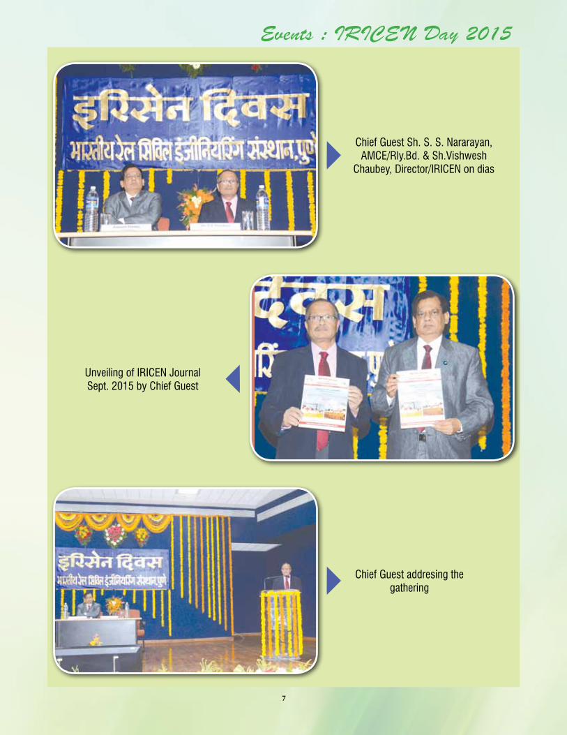
Events : IRICEN Day 2015
Chief Guest Sh. S. S. Nararayan, AMCE/Rly.Bd. & Sh.Vishwesh
Chaubey, Director/IRICEN on dias
Unveiling of IRICEN JournalSept. 2015 by Chief Guest
Chief Guest addresing the gathering
8
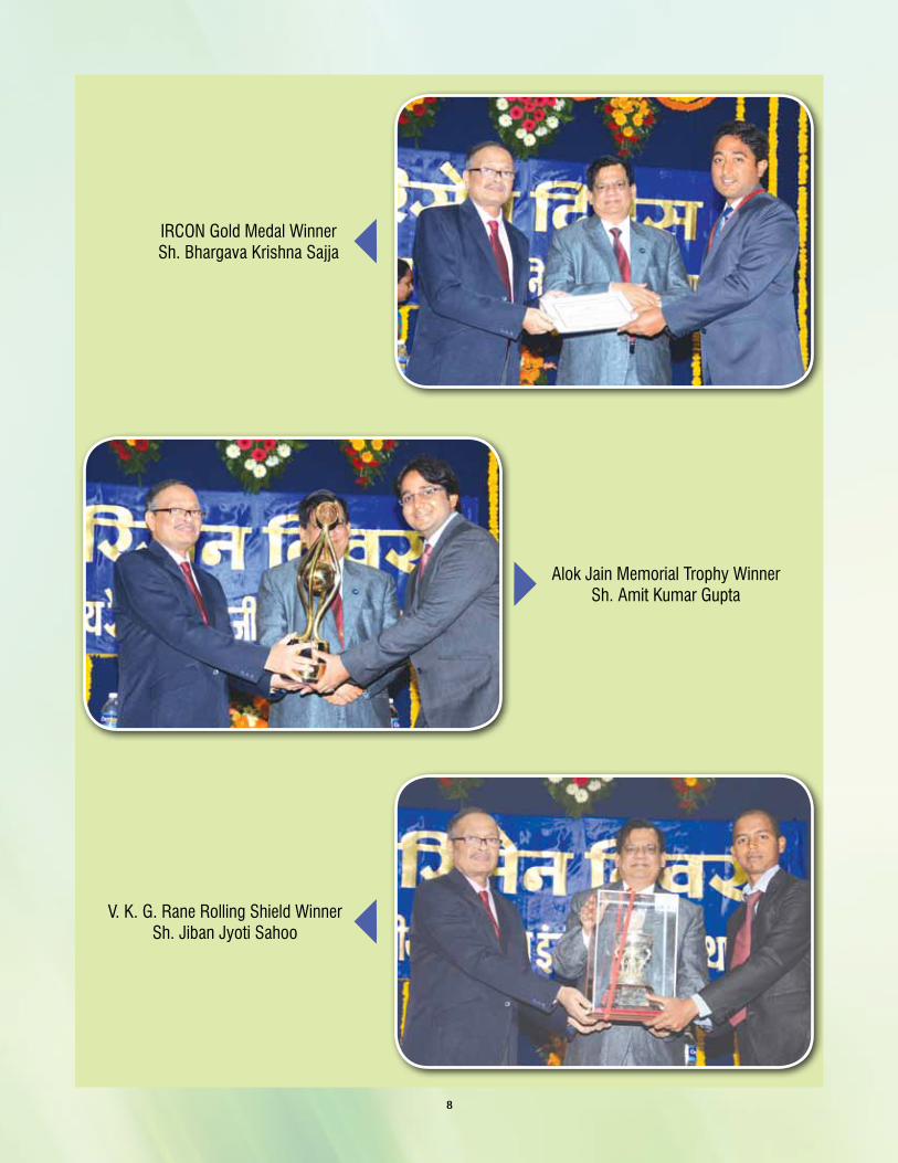
IRCON Gold Medal Winner Sh. Bhargava Krishna Sajja
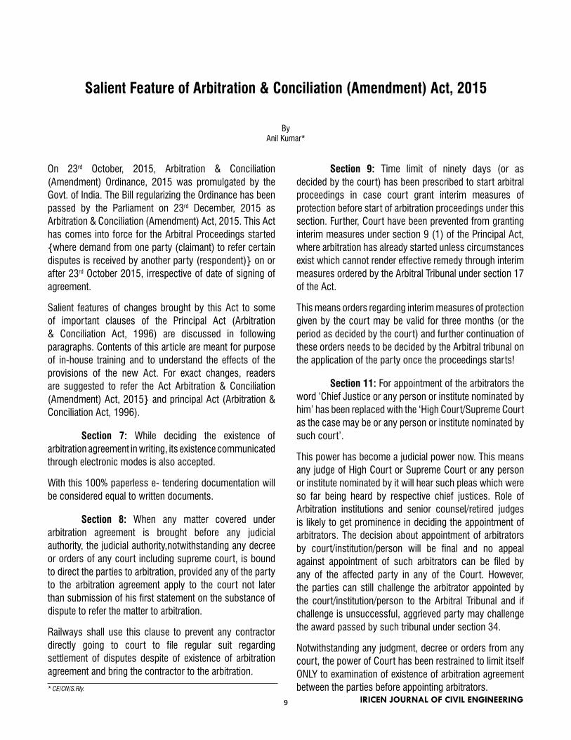
Alok Jain Memorial Trophy Winner Sh. Amit Kumar Gupta
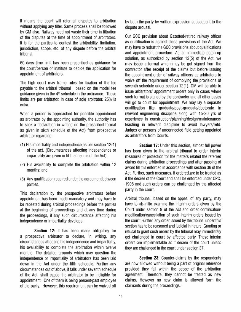
V. K. G. Rane Rolling Shield Winner Sh. Jiban Jyoti Sahoo
9
Salient Feature of Arbitration & Conciliation (Amendment) Act, 2015
ByAnil Kumar*
On 23rd October, 2015, Arbitration & Conciliation (Amendment) Ordinance, 2015 was promulgated by the Govt. of India. The Bill regularizing the Ordinance has been passed by the Parliament on 23rd December, 2015 as Arbitration & Conciliation (Amendment) Act, 2015. This Act has comes into force for the Arbitral Proceedings started {where demand from one party (claimant) to refer certain disputes is received by another party (respondent)} on or after 23rd October 2015, irrespective of date of signing of agreement.
Salient features of changes brought by this Act to some of important clauses of the Principal Act (Arbitration & Conciliation Act, 1996) are discussed in following paragraphs. Contents of this article are meant for purpose of in-house training and to understand the effects of the provisions of the new Act. For exact changes, readers are suggested to refer the Act Arbitration & Conciliation (Amendment) Act, 2015} and principal Act (Arbitration & Conciliation Act, 1996).
Section 7: While deciding the existence of arbitration agreement in writing, its existence communicated through electronic modes is also accepted.
With this 100% paperless e- tendering documentation will be considered equal to written documents.
Section 8: When any matter covered under arbitration agreement is brought before any judicial authority, the judicial authority,notwithstanding any decree or orders of any court including supreme court, is bound to direct the parties to arbitration, provided any of the party to the arbitration agreement apply to the court not later than submission of his first statement on the substance of dispute to refer the matter to arbitration.
Railways shall use this clause to prevent any contractor directly going to court to file regular suit regarding settlement of disputes despite of existence of arbitration agreement and bring the contractor to the arbitration.
* CE/CN/S.Rly.
Section 9: Time limit of ninety days (or as decided by the court) has been prescribed to start arbitral proceedings in case court grant interim measures of protection before start of arbitration proceedings under this section. Further, Court have been prevented from granting interim measures under section 9 (1) of the Principal Act, where arbitration has already started unless circumstances exist which cannot render effective remedy through interim measures ordered by the Arbitral Tribunal under section 17 of the Act.
This means orders regarding interim measures of protection given by the court may be valid for three months (or the period as decided by the court) and further continuation of these orders needs to be decided by the Arbitral tribunal on the application of the party once the proceedings starts!
Section 11: For appointment of the arbitrators the word ‘Chief Justice or any person or institute nominated by him’ has been replaced with the ‘High Court/Supreme Court as the case may be or any person or institute nominated by such court’.
This power has become a judicial power now. This means any judge of High Court or Supreme Court or any person or institute nominated by it will hear such pleas which were so far being heard by respective chief justices. Role of Arbitration institutions and senior counsel/retired judges is likely to get prominence in deciding the appointment of arbitrators. The decision about appointment of arbitrators by court/institution/person will be final and no appeal against appointment of such arbitrators can be filed by any of the affected party in any of the Court. However, the parties can still challenge the arbitrator appointed by the court/institution/person to the Arbitral Tribunal and if challenge is unsuccessful, aggrieved party may challenge the award passed by such tribunal under section 34.
Notwithstanding any judgment, decree or orders from any court, the power of Court has been restrained to limit itself ONLY to examination of existence of arbitration agreement between the parties before appointing arbitrators.
IRICEN JOURNAL OF CIVIL ENGINEERING
10
It means the court will refer all disputes to arbitration without applying any filter. Same process shall be followed by GM also. Railway need not waste their time in filtration of the disputes at the time of appointment of arbitrators. It is for the parties to contest the arbitrability, limitation, jurisdiction, scope, etc. of any dispute before the arbitral tribunal.
60 days time limit has been prescribed as guidance for the court/person or institute to decide the application for appointment of arbitrators.
The high court may frame rules for fixation of the fee payable to the arbitral tribunal based on the model fee guidance given in the 4th schedule in the ordinance. These limits are per arbitrator. In case of sole arbitrator, 25% is extra.
When a person is approached for possible appointment as arbitrator by the appointing authority, the authority has to seek a declaration in writing (in the prescribed format as given in sixth schedule of the Act) from prospective arbitrator regarding:
(1) His impartiality and independence as per section 12(1) of the act. (Circumstances affecting independence or impartiality are given in fifth schedule of the Act);
(2) His availability to complete the arbitration within 12 months; and
(3) Any qualification required under the agreement between parties.
This declaration by the prospective arbitrators before appointment has been made mandatory and may have to be repeated during arbitral proceedings before the parties at the beginning of proceedings and at any time during the proceedings, if any such circumstance affecting his independence or impartiality develops.
Section 12: It has been made obligatory for a prospective arbitrator to declare, in writing, any circumstances affecting his independence and impartiality, his availability to complete the arbitration within twelve months. The detailed grounds which may question the independence or impartiality of arbitrators has been laid down in the Act under the fifth schedule. Further any circumstances out of above, if falls under seventh schedule of the Act, shall cause the arbitrator to be ineligible for appointment. One of them is being present/past employee of the party. However, this requirement can be waived off
by both the party by written expression subsequent to the dispute arousal.
Our GCC provision about Gazetted/retired railway officer as qualification is against these provisions of the Act. We may have to redraft the GCC provisions about qualifications and appointment procedure. As an immediate patch-up solution, as authorized by section 12(5) of the Act, we may issue a format which may be got signed from the contractor after receipt of the claims but before issuing the appointment order of railway officers as arbitrators to waive off the requirement of complying the provisions of seventh schedule under section 12(1). GM will be able to issue arbitrators’ appointment orders only in cases where such format is signed by the contractor and all other cases will go to court for appointment. We may lay a separate qualification like graduate/post-graduate/doctorate in relevant engineering discipline along with 15-20 yrs of experience in construction/planning/design/maintenance/teaching in relevant discipline to avoid lawyers/retd. Judges or persons of unconnected field getting appointed as arbitrators from Courts.
Section 17: Under this section, almost full power has been given to the arbitral tribunal to order interim measures of protection for the matters related the referred claims during arbitration proceedings and after passing of award till it is enforced in accordance with section 36 of the Act. Further, such measures, if ordered,are to be treated as if the decree of the Court and shall be enforced under CPC, 1908 and such orders can be challenged by the affected party in the court.
Arbitral tribunal, based on the appeal of any party, may have to ab-initio examine the interim orders given by the Court under section 9 of the Act and order continuation/modification/cancellation of such interim orders issued by the court! Further, any order issued by the tribunal under this section has to be reasoned and judicial in nature. Granting or refusal to grant such orders by the tribunal may immediately get challenged in court by affected party. These interim orders are implementable as if decree of the court unless they are challenged in the court under section 37.
Section 23: Counter-claims by the respondents are now allowed without being a part of original reference provided they fall within the scope of the arbitration agreement. Therefore, they cannot be treated as new claims. However no new claim is allowed form the claimants during the proceedings.
11
Section 24:Arbitral tribunal to hold hearings on day to day basis and not supposed to grant any adjournment without sufficient cause and has been given powers to impose exemplary cost on a party if the party seeks adjournment without sufficient cause.
Parties may have to fully prepare themselves with all relevant evidences, documents, arguments, legal citations, etc. for continuous hearings without adjournments. Non availability of parties’ counsel may not be a reason for adjournments.
Section 25: Failure of respondents to file statement of defence will be treated as waiver of his right to file such statement of defence.
Railways shall file their defence statement in given time to prevent their right getting waived off, otherwise shall get extension before expiry of such time from the tribunal.
Section 28: It has been made compulsory for Arbitral Tribunal to decide in all cases duly considering the terms of the agreement between parties and usages of trade applicable to transaction.
Preprinted no-claim certificate in the bill format may not be acceptable as valid document unless a separate no-claim certificate (supplementary agreement) is obtained. Railway’s respondent to highlight various agreement conditions at appropriate time and file objections before the tribunal during hearings to prevent the tribunal going beyond jurisdiction and scope.
Section 29 A: Twelve month time period, from the date of receipt of appointment notice, has been prescribed as a time limit for the tribunal for making the award. It may be further extended by six months by the parties. However,further extension if any, will require orders from the Court based on the sufficient reasons.
Provision also made for incentives, as well as penalties on the fees of arbitrators for completion of award within six month and delayed completion of award beyond 18 month. The court may substitute the arbitrator(s) and impose certain conditions while granting extensions beyond 18 months. Court may impose exemplary cost on any party while granting such extension.
The mandate of the arbitral tribunal gets terminated after 12/18 month if extension not granted. Therefore all efforts shall be made to pass the award within 12 month.
Section 29B: There is a provision of fast track arbitration which is required to be completed within 6 months where only the written submission/documents/evidences are to be accepted. No oral hearings are allowed. For such arbitration process, parties to give their request before or at the time of appointment of arbitrators. Here parties may agree for sole arbitrator to be appointed by them.
For the purpose of fast track arbitration, a power is given to the tribunal to ask for additional evidences/clarifications from the parties through oral/documentary based if some gaps are found by the tribunal in their written submission. No such power exists for normal arbitration where tribunal cannot use its personal knowledge.
Section 31: The award may carry interest at the rate of 2% higher than the “current rate” prevailing on the date of award from the date of award to the date of payment if nothing is specified in the award.
Railway shall make specific plea for lower rate of interest and any interest free grace period needed for making payment. In Railway cases involving works contracts, no power is given to arbitral tribunal to award interest from date of cause of action till date of award.
Section 31A: Unless the parties expressly agree in writing,after arousal of the dispute, for equal cost sharing, the tribunal has been given power to generally award cost against unsuccessful party or a proportion of it keeping in mind of conduct of parties during the proceedings and success rate of a party with respect to his claim amount duly recording of reasons in writing. Manner and method of payment of such cost to be decided by the tribunal. Cost to include all expenses, including fee, during the proceedings and any other incidental expenses prior to proceedings. Factors affecting the conduct of the parties and method of cost apportionment has been given in this section.
Tribunal may follow same procedure in respect of counter claims also. Railway may devise a format which may have to be signed by the contractor, post dispute arousal, at the time of appointment of arbitrators, for equal sharing of the cost.
Section 34: The award can be set aside by the court only for the reasons given in this section of the Act and further it has been laid down that while testing whether there is a contravention with the fundamental policy of Indian Law, no review on the merit of the dispute can be
12
Did you know ?• The brain uses over a quarter of the oxygen used by the human body• If you sneeze too hard, you could fracture a rib• ‘Dreamt’ is the only English word that ends in the letters mt.• Australia is the only continent in the world that has no volcanoes• Hawaii is moving towards Japan at the speed of 10 cm a year. This is because they are on different
tectonic plates• The ‘sixth sick sheik’s sixth sheep’s sick’ is believed to be the toughest tongue twister in English
language• Lipsticks are not vegan cosmetics! More than 95% of lipsticks contain fish scales!• Kangaroos cannot walk backwards!• Venus is the only planet in the solar system that rotates clockwise, whereas all other planets rotate anti-
made by the court. Similarly while deciding the issue of patent illegality appearing of the face of a word award, the award cannot be set aside by the court on the ground of an erroneous application of the law or by re appreciation of the evidence.
An exhaustive list of reasons has been given in this section on account of those ONLY, the aware can be set aside by the court. Court do not have any power to modify the award or to go into merit of evidences considered by the tribunal. Procedural lapses during the arbitral proceedings alone constitute most of these reasons.
Railways to quickly study the award for any possible correction, interpretation or omitted claims for which immediate reference (within 30 days) to be made to the tribunal for correction of such errors. Railway itself cannot correct any error, and uncorrected errors (even it is typographical error, calculation mistake, etc.), if any, becomes enforceable award.
Defending officer should submit any procedural violation by the tribunal, viz. dealing of any claim beyond jurisdiction, scope, defective appointment of tribunal, etc. duly bringing out the steps taken to prevent the same during the proceedings so that the award may be challenged within 90 days. Any delay beyond 90 days, a party has to explain each and every day delay from day 1 before the court to get extension of 30 days.
The court has been given one year time to dispose of the award challenging application. To file an award challenge
application in court, a prior notice to another party is a must.
Section 36: While accepting application under section 34 for challenge to the award, an award automatically does not get stayed unless otherwise specifically ordered by the court based on a separate application filed by a party. While granting stay of operation of award, court has to record reasons and to have due regards about provisions of grant of stay in money decree under CPC, 1908.
Court may ask the party to pay/deposit a substantial part of awarded amount before granting stay.
Fourth Schedule: A model fee structure for the arbitrators has been prescribed which is to be kept in mind by court while making rules of fee payment to arbitrators
Fifth schedule: 31 grounds have been specified which may give rise to justifiable doubts about independence or impartiality of arbitrators.
Sixth schedule: A format of declaration to be given by the prospective arbitrators to the appointing authority before his appointment and during the arbitral proceedings.
Seventh schedule: 19 grounds have been specified which may give rise to justifiable doubts about independence or impartiality of arbitrators and existing of any of them makes a person in-eligible for appointment as arbitrators.
13
Evolution of Locomotives on Indian Railways
By S.K.Bansal * R.A.Sayyad**
Synopsis: To know the evolution of locomotives over the period of 162 years beginning with first steam loco hauled train covering 33 kms to thousands of daily trains running on route kms of over 66,000.
Introduction :
Indian Railways provide an important mode of transport in India, transporting over 8397 million passengers and more than 1052 million tonnes of freight daily across one of the largest and busiest rail networks in the world. As to rolling stock, IR owns over 2,45,300 (freight) wagons, 59,600 coaches and 10,500 locomotives. India’s Rail network is 4th longest in world which is heavily used system in the world.
During the course of evolution of Locomotives on IR, a lot of technological up gradation have been carried out in Railway system. Development in Locomotives over the years are discussed,
Diesel Traction :
Due to inherent disadvantages in steam traction such as less haulage capacity, low speed, low efficiency of engine, less efficient vacuum brakes, frequent water & coaling halts etc. Railways started switching over to Diesel Traction in 1957 onwards. Initially, WDM1 locomotive was imported from America and was inducted in IR fleet of locomotives in 1957. Steam and Electric Locomotives were earlier
providing the services.
WDM2 Locomotive :
Railways entered into Contract with American Loco Company (ALCO) for purchase of WDM2 locomotives with Transfer of Technology (TOT) agreement. 40 locomotives fully assembled were imported in 1962 and in the same year, Diesel Locomotive Works (DLW) started assembling WDM2 locomotives under TOT. Assembly of imported WDM2 loco parts and also development of indigenous sources for major spare parts continued for about 3 decades.
During the same year 1962, WDM4 locomotives having 2 stroke Engine with power rating of 2600HP at 835 RPM, Max.TE: 28.2t (28200kg) & Gear Ratio- 61:16 were also imported and introduced in IR fleet which were based at Mugalsarai shed of Northern Railway.
However, WDM2 was the most popular Loco till 1994 in Diesel Traction segment. The loco has following Technical features
Engine
typePower RPM
Gear
ratioSpeed
Tr.
effort
Type of
Transmission
4 stroke,
16 cyl
2600
HP
400/
100065:18
120
Kmph30.45 t DC-DC
Horse power of WDM2 was initially 2600 HP which was found insufficient for growing demand of hauling longer coaching & heavier goods trains. Use of Multiple units on Goods trains was ok but for coaching trains, it was excess power for 18/19 coach trains from originally 16 coach trains by utilizing one extra loco for slightly higher power requirement.*Sr. Prof/Project/IRICEN
**SI/Mech-II
IRICEN JOURNAL OF CIVIL ENGINEERING
14
As such Alco locomotives were upgraded to a number of variants over the period-
Major variants of Alco locos are-
Class Year MakerWheels & Bogie type
Power Speed WeightStarting
TE
(hp) (km/h) (tonnes)(kg
force)
WDM-3A 1994+ DLWCo-Co (tri mount)
3100 120 112.8 30450
WDG-3A 1995+ DLWCo-Co (High Adhesion)
3100 100 123 37900
WDM-3D 2003 DLWCo-Co(High speed High Adhesion)
3300 120 117 36036
WDM3A Locomotive of 3100 HP
WDM3D Locomotive of 3300 HP
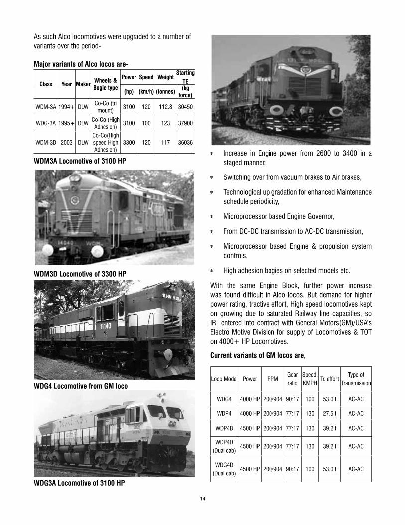
WDG4 Locomotive from GM loco
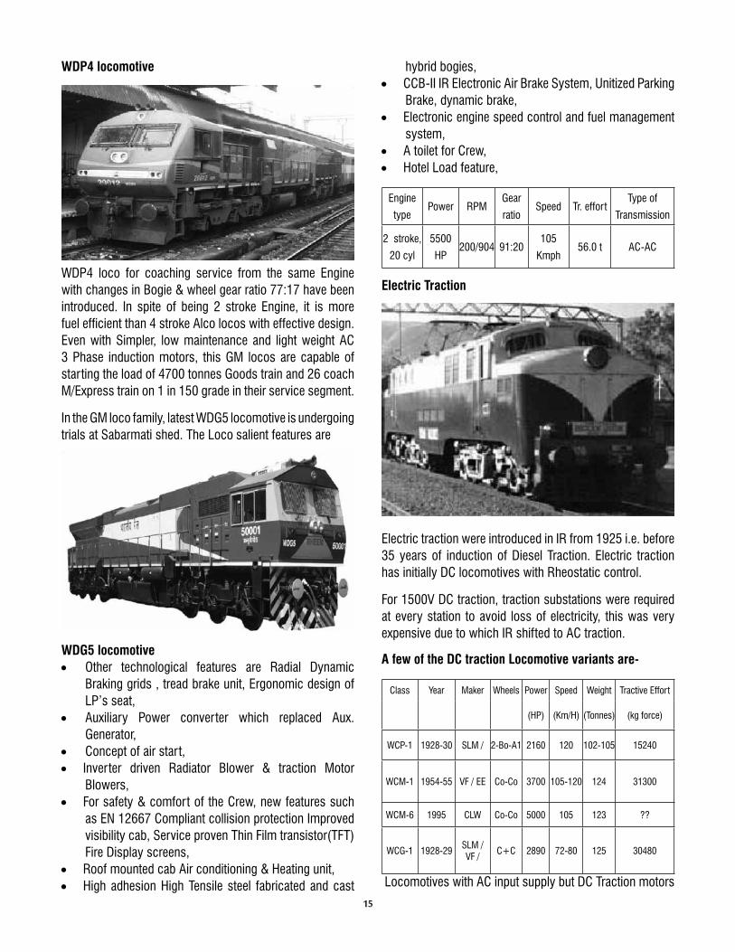
WDG3A Locomotive of 3100 HP
* Increase in Engine power from 2600 to 3400 in a staged manner,
* Switching over from vacuum brakes to Air brakes,
* Technological up gradation for enhanced Maintenance schedule periodicity,
* Microprocessor based Engine Governor,
* From DC-DC transmission to AC-DC transmission,
* Microprocessor based Engine & propulsion system controls,
* High adhesion bogies on selected models etc.
With the same Engine Block, further power increase was found difficult in Alco locos. But demand for higher power rating, tractive effort, High speed locomotives kept on growing due to saturated Railway line capacities, so IR entered into contract with General Motors(GM)/USA’s Electro Motive Division for supply of Locomotives & TOT on 4000+ HP Locomotives.
Current variants of GM locos are,
Loco Model Power RPMGear ratio
Speed, KMPH
Tr. effortType of
Transmission
WDG4 4000 HP 200/904 90:17 100 53.0 t AC-AC
WDP4 4000 HP 200/904 77:17 130 27.5 t AC-AC
WDP4B 4500 HP 200/904 77:17 130 39.2 t AC-AC
WDP4D (Dual cab)
4500 HP 200/904 77:17 130 39.2 t AC-AC
WDG4D (Dual cab)
4500 HP 200/904 90:17 100 53.0 t AC-AC
15
WDP4 locomotive
WDP4 loco for coaching service from the same Engine with changes in Bogie & wheel gear ratio 77:17 have been introduced. In spite of being 2 stroke Engine, it is more fuel efficient than 4 stroke Alco locos with effective design. Even with Simpler, low maintenance and light weight AC 3 Phase induction motors, this GM locos are capable of starting the load of 4700 tonnes Goods train and 26 coach M/Express train on 1 in 150 grade in their service segment.
In the GM loco family, latest WDG5 locomotive is undergoing trials at Sabarmati shed. The Loco salient features are
WDG5 locomotive• Other technological features are Radial Dynamic
Braking grids , tread brake unit, Ergonomic design of LP’s seat,
• Auxiliary Power converter which replaced Aux. Generator,
• Concept of air start,• Inverter driven Radiator Blower & traction Motor
Blowers,• For safety & comfort of the Crew, new features such
as EN 12667 Compliant collision protection Improved visibility cab, Service proven Thin Film transistor(TFT) Fire Display screens,
• Roof mounted cab Air conditioning & Heating unit,• High adhesion High Tensile steel fabricated and cast
hybrid bogies,• CCB-II IR Electronic Air Brake System, Unitized Parking
Brake, dynamic brake,• Electronic engine speed control and fuel management
system,• A toilet for Crew,• Hotel Load feature,
Engine
typePower RPM
Gear
ratioSpeed Tr. effort
Type of
Transmission
2 stroke,
20 cyl
5500
HP200/904 91:20
105
Kmph56.0 t AC-AC
Electric Traction
Electric traction were introduced in IR from 1925 i.e. before 35 years of induction of Diesel Traction. Electric traction has initially DC locomotives with Rheostatic control.
For 1500V DC traction, traction substations were required at every station to avoid loss of electricity, this was very expensive due to which IR shifted to AC traction.
A few of the DC traction Locomotive variants are-
Class Year Maker Wheels Power Speed Weight Tractive Effort
Up to 1980s, only DC Series Motors were considered suitable for traction application due to their inherent torque/ speed characteristics suitable for vehicle propulsion. Torque/speed control is achieved by variation of input voltage to traction motor. This is achieved by introduction of starting resistance in DC locos. With DC drive, problems experienced were
• Traction Motor Maintenance cost high,
• Stepped control- less adhesion,
• Higher un sprung mass,
• High life cycle cost.
Due to this, Railways switched over to 3 phase
AC Locomotives which has many advantages Works on Single phase AC-25KV, 50Hz supply but Traction Motors
are 3 phase induction motors,
• Simple squirrel cage induction motors used,
• Torque/ Speed characteristics modified to suit traction application with the help of Variable voltage variable frequency (VVVF),
• Low maintenance due to induction motors,
• Energy saving due to regeneration,
• Unity Power factor,
• Adhesion characteristics better, • Life cycle cost low
WAP5 Locomotive
Landmarks of 3 phase locomotives
• 1993- TOT agreement between IR & ABB Transportation Systems, Zurich Switzerland 1996: Six WAG-9 locos and 16 more in kit form imported from ABB (AdTranz) 1998: CLW begins production of indigenous versions of WAG-9
• 2000:First indigenous WAP-5 (named ‘Navodit’) from CLW
• 2000 :First WAG-9H locomotive ‘Navshakti’
• 2009 –First WAG-9i with IGBT based Traction Converter (Advantages on pg6)
• 2010 –First WAP-7 with Head on Generation Scheme. (Schematic & Adv on pg6)
• 2010 –First full IGBT WAG-9
• 2011 –First WAG-9H with Locotrol
17
Class Year Maker Wheels Power Speed Weight Tractive Effort
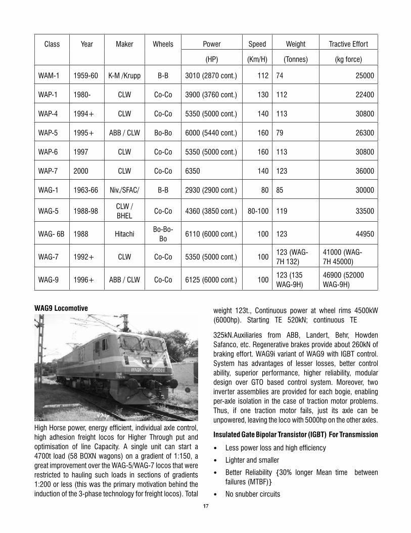
High Horse power, energy efficient, individual axle control, high adhesion freight locos for Higher Through put and optimisation of line Capacity. A single unit can start a 4700t load (58 BOXN wagons) on a gradient of 1:150, a great improvement over the WAG-5/WAG-7 locos that were restricted to hauling such loads in sections of gradients 1:200 or less (this was the primary motivation behind the induction of the 3-phase technology for freight locos). Total
weight 123t., Continuous power at wheel rims 4500kW (6000hp). Starting TE 520kN; continuous TE
325kN.Auxiliaries from ABB, Landert, Behr, Howden Safanco, etc. Regenerative brakes provide about 260kN of braking effort. WAG9i variant of WAG9 with IGBT control. System has advantages of lesser losses, better control ability, superior performance, higher reliability, modular design over GTO based control system. Moreover, two inverter assemblies are provided for each bogie, enabling per-axle isolation in the case of traction motor problems. Thus, if one traction motor fails, just its axle can be unpowered, leaving the loco with 5000hp on the other axles.
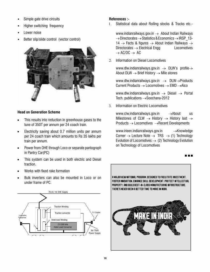
Insulated Gate Bipolar Transistor (IGBT) For Transmission
• Less power loss and high efficiency
• Lighter and smaller
• Better Reliability {30% longer Mean time between failures (MTBF)}
• No snubber circuits
18
• Simple gate drive circuits
• Higher switching frequency
• Lower noise
• Better slip/slide control (vector control)
Head on Generation Scheme
• This results into reduction in greenhouse gases to the tune of 350T per annum per 24 coach train.
• Electricity saving about 0.7 million units per annum per 24 coach train which amounts to Rs 35 lakhs per train per annum.
• Power from OHE through Loco or separate pantograph in Pantry Car(PC)
• This system can be used in both electric and Diesel traction.
• Works with fixed rake formation
• Bulk inverters can also be mounted in Loco or on under frame of PC.
References :-1. Statistical data about Rolling stocks & Tracks etc.-
www.indianrailways.gov.in → About Indian Railways →Directorates →Statistics & Economics →IRSP_13-14 → Facts & figures →About Indian Railways → Directorates →Electrical Engg Locomotives →AC/DC → AC
2. Information on Diesel Locomotives
www.dlw.indianrailways.gov.in → DLW’s profile→About DLW →Brief History → Mile stones
www.dlw.indianrailways.gov.in → DLW→Products Current Products →Locomotives →EMD →Alco
www.clw.indianrailways.gov.in →About us Milestones of CLW → History → History last →Products →Locomotives →Recent Developments
www.irieen.indianrailways.gov.in →Knowledge Corner →Lecture Note → TRS →(1) Technology Evolution of Locomotives → (2) Technology Evolution on Technology of Locomotives
25 kV, 1F OHE Supply
3F 750V Power Supply
I V Coupler Traction converter
Hotel load Winding
2 X 500 kVaHotel Load Converter
Traction Winding
LocomotiveTransformer
19
Long Life Painting Scheme for Cable Stayed ROB at Barddhaman
By Harsimran Singh *
Synopsis :A very important and complex bridge project in under execution at Barddhaman railway yard for rebuilding of existing distressed ROB which crosses ten railway lines and all platforms. The maintenance of this structure will not be possible in usual manner and hence the necessity of maintenance particularly painting has to be reduced. This led to the adoption of long life painting scheme. Such scheme can be replicated in other important and critical bridge projects.
1.0 Background:
Bardhaman is situated at 107 km from Howrah on Howrah-Delhi route. There is an old multi span ROB of brick masonry construction over the Bardhaman railway yard, which is connecting the G.T.Road side of Bardhaman town with Kalna-Katwa Road. The existing ROB is an extremely busy corridor carrying a large number of fast and slow moving vehicles along with pedestrian traffic. Due to its distressed condition, rebuilding of the existing ROB had been sanctioned at a cost of ` 156.68Crore (SF - ` 60.35Crore, Deposit- ` 96.33Crore) in 2009-10 as a 4 lane cable stayed ROB. A cable stayed ROB was the only option acceptable to Railways and the State Govt in this very busy Yard connecting very busy GT road on one side with two important roads on the other side. RVNL had been entrusted by the Eastern Railway to construct the new cable stayed ROB. On 2nd March, 2011, RVNL engaged Consulting Engineering Services ( I ) Pvt. Ltd (CES) as consultant for carrying out detail design and construction supervision. IIT, Roorkee had been assigned the task of proof checking of design, specifications and manuals. M/s GPT-RANHILL JV had been awarded the work of construction of the Cable Stayed Portion of the ROB. The proposed ROB is being constructed at a distance of 65.5m towards Durgapur from the existing ROB (c/c distance). In order to have a clear hindrance free span over the Bardhaman railway yard the proposed new ROB has cable stayed construction in a span of 188.429m(c/c). The main span of the cable stayed portion is a composite girder
of high tensile steel and M-50 RCC. The pylon is part RCC structure upto deck level and has three steel box towers of high tensile steel above deck level. There is about 2000MT structural steel and about 190MT Stay Cables. The height of the towers above ground level is about 68M. These all factors make regular maintenance including painting of structural steel a quite difficult task.
2.0 Necessity of Painting Steel Structures:
Painting of the steel surfaces is essential to prevent it`s corrosion and increase the life, apart from enhancing the aesthetic appearance. Corrosion is deterioration of metal due to its interaction with the corroding environment. When steel is exposed to the atmosphere, it combines chemically with the oxygen to form oxides. This is generally described, as rust. In addition, steel gets corroded by other harmful chemicals to which it may be exposed, such as acidic fumes and salt in sea spray etc. Corrosion may take place in either of the following forms:
i) Uniformly over large areas, referred to as “Uniform corrosion” or limited over a local area, referred to as “local corrosion”;
ii) Restricted to an extremely minute area, referred to as “pitting”.
Corrosion can be prevented by
a) Protective coatings by painting,
b) Metallizing - a form of protection by spraying a metal either zinc or Aluminium,
*DGM(G), SE Railway
IRICEN JOURNAL OF CIVIL ENGINEERING
20
c) Use of epoxy based paints.
3.0 Conventional Bridge Painting of Railway Steel Bridges: The following systems of paints are proposed for painting of steel Bridge girders in the Indian Railway Bridge Manual :
a) In areas where there is no severe corrosion
i) Priming coat : One coat of ready mixed paint zinc chromate priming to IS : 104 followed by one coat of ready mixed paint red oxide zinc chrome priming paint to IS : 2074; or Two coats of zinc chromate red oxide primer to IRS - P – 31.
ii) Finishing coat: Two cover coats of red oxide paint to IS : 123 or any other approved paint applied over the primer coats.
b) In areas where corrosion is SEVERE
i) Priming Coat: One coat of ready mixed paint zinc chromate priming to IS: 104 followed by one coat of zinc chrome - red oxide priming to IS : 2074
ii) Finishing coat: Two coats of aluminium paint to IS : 2339.
c) For locations where girders are directly exposed to corrosive environment such as girders in industrial, suburban or coastal areas, etc., protective coating by way of metallizing or by painting with epoxy based paints may be applied.
Epoxy based Paints: The surface is prepared by sand or grit blasting to Sa 2½ to IS : 9954, i.e., near white metallic surface and then painted with two coats of primer coat of epoxy zinc phosphate primer to RDSO specification No. M & C /PCN-102/86 to 60 microns minimum dry film thickness (DFT) applied by brush / airless spray giving sufficient time gap between two coats to enable first coat of primer to hard dry.
Intermediate coat of epoxy micaceous iron oxide to RDSO specification No. M & C /PCN-103/86 to 100 microns minimum DFT applied by brush/airless spray.
Two finishing coats of polyurethane aluminium finishing to RDSO Specification No. M & C /PCN-110/88 for coastal locations or polyurethane red oxide (red oxide to ISC 446 as per IS : 5) to RDSO Specification No. M&C/PCN-109/88 for other locations to 40 microns minimum DFT applied by brush/airless spray giving sufficient time gap between two coats to enable the
first coat to hard dry. The finishing coats are applied in shop and touched after erection, if necessary. This scheme is a form of long life painting system but is not very popular.
4.0 Requirement of Long life painting scheme for important structures: In very important structures where regular painting will be difficult due to site constrains, it is necessary to have long life paints applied at the time of construction. This will not only improve the life of the structure by preventing corrosion but will also reduce the requirement of the regular painting which is normally done every 5 years. Long life paints have a life of 15-20 years.
5.0 International Guidelines:
Paint as per ISO:8503 is used now a days in important structures. A report has also been issued by RDSO (Report No-130) in Nov 2009 where painting scheme in line with this system has been discussed. The long life painting system as per ISO:8503 has been adopted for cable stayed ROB under construction at Barddhaman. The ROB has composite deck in main span and three steel towers as pylon structure. On the steel structure long life paint of M/s Akzo Nobel is being applied. The painting scheme consists of sand blasting & surface preparation to Sa 2 1/2 of DIN EN ISO:12944, part-4 with sharp edged material roughness according to ISO:8503/1, Type G Segment 2-3 consisting of
(i) Prime coat of 2-C Epoxy Zinc dust having film thickness of 75µm, product Interzinc 52, colour gray
(ii) Intermediate coat of 2-C High Build MIO having film thickness of 125µm, product Intergard 475HS, colour shade according to RAL
(iii) Top coat consisting of 2-C Polysiloxan long time over coatable top coat having film thickness of 120 µm, product Inter fine 878, colour shade according to RAL.
6.0 Detailed Procedure for Painting :
6.1 Surface Preparation: To provide a surface which will ensure optimum coating performance, preparation is required to remove sharp edges from the surface which include, but are not limited to, plate edges, weld spatter, plate laminations, weld undercuts, or gas cut surfaces. Oil or grease, salts, dirts, chalk marks and similar contaminants shall be removed
21
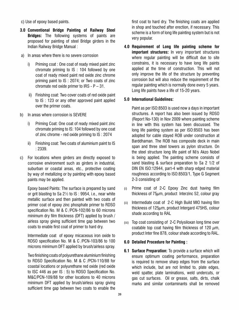
as far as possible, prior to surface preparation, using an appropriate method in accordance with ISO:12944,part-4. Sharp Edges, weld spatter, cavities and deformations are to be removed in accordance with ISO:8501/3, table-3. Assess the steel surface for Rust grades as per ISO:8501/1. Surface shall be cleaned by abrasive blast cleaning (ISO:12944/4, Cl.6.2.3.1.2) in accordance with ISO:8504/2, Cl. 5.1.2. Surface cleanliness shall be as per Sa 2 1/2 and surface profile shall have deflectometer reading 50-75µ in accordance with ISO:8502/4. Compressed air used for blasting must be clean, oil free and dry. Moisture and Oil separators should be used to ensure the same. The pressure should be at least 7kg per cm2 (100lbs per inch2) at the nozzle. Abrasive used for blasting should be dry and free from dirt, oil, grease or contamination and have content of water soluble matter not exceeding 0.05%. It must be capable of producing the standard of cleanliness and surface profile specified. Abrasives like copper slag should not be recycled more than once, and should not be contaminated with soil. Before initial blast inspection, the spent abrasive should be removed. Any substandard areas should be identified and repaired. All markings of paint, chalk, etc., must be removed after rectification. Fabrication repair (if any) should be carried out before application of the primer. Following inspection of the blast profile and standard, remaining traces of abrasive and dust
Fig : 1 Slag Fig . : 2 Checking Surface Roughness
should be removed from all areas.
6.2 Paint Application: Surfaces to be coated must have a temperature at least 3ºC (5ºF) above the dew point, immediately following blasting and priming, intermediate and topcoat application, and must also remain in this condition during curing of the coatings. As a guide, relative humidity levels of 25-80% give optimum painting conditions, although
some applications may be carried out up to 85% relative humidity. Painting can be carried out on steel temperature up to 45ºC. Painting should not be carried out during windy conditions.
6.3 General Site Requirements : Prior to any work being carried out there are a number of conditions which must be met.
a) Cleanliness : Any contaminants which may come in contact with the steel (even before surface preparation commences) can compromise the performance of protective coating system, and as such all effort must be made to keep the working area clean. It is good working practice to establish a clean area where painting is being done. Cleanliness must be maintained throughout all stages of the application.
b) Weather Shelters : Weather shelters should be made available to cover application equipment during mixing and application of material.
c) Paint Storage Facility : All paints should be stored ideally between 10ºC (50ºF) and 30ºC (86ºF) and facilities may be needed to store the materials in the correct temperature range prior to mixing and application.
6.4 Stripe Coating : Stripe coating is an essential part of good working practice and stripe coats are highlighted in the detailed product specification sheets. Stripe coats are applied to areas where it is difficult to get the required coverage, including but not limited to:- plate edges, welds and difficult access areas. Stripe coats are normally applied to a specified film thickness range via a combination of narrow angle airless spray and brush methods. Overcoating intervals for the stripe coats should be strictly adhered to as per the individual product data sheets.
6.5 Paint Specifications:
6.5.1 Primer Coat: Inter zinc 52, 75 micorn DFT applied by airless spray, air spray, brush & roller. Mixing Ratio of 4 : 1 by volume (Base : Hardener) is adopted. Mix the base using a power agitator. Add C/A slowly during mixing and mix well for 5 minutes. Ensure complete mixing of Base and C/A. If 20 litres complete mixing is not possible then proper measuring jars should be employed to ensure accuracy. This should be ensured for all coats - intermediate, top and touch up coats. Tip size adopted is 0.43 - 0.53 mm (17-21
22
Fig. 4 Checking Intermediate Coat
thou). Output fluid pressure at spray tip should be not less than 176kg/cm2(2,503 p.s.i.). Thinner GTA220 is used when required. The thinner consumption should not exceed more than 20%. Check WFT during application using comb gauge. For 75 microns DFT, the WFT would be 127 microns.
Fig. : 3 Checking Primer Coat
6.5.2 Intermediate coat: Intergard 475HS, 125 micron DFT applied by airless Spray, air spray, or brush & roller. Mixing Ratio adopted is 3 : 1 by volume (Base : Hardener). Tip size adopted is 0.53 - 0.63 mm (21-25 thou). Output fluid pressure at spray tip should be not less than 190 kg/cm2 (2,702 p.s.i.). Thinner GTA007 is used only when required and the thinner consumption should not exceed more than 15%. WFT should be checked during application using comb gauge. For 125 microns DFT, the WFT shall be 156 microns
6.5.3 Top coat: Inter fine 878, 60 micron DFT applied by airless spray, air spray, or brush & roller. Mixing ratio adopted is 5 : 1 by volume(Base : Hardener). Tip size adopted is 0.28 - 0.43 mm (11-17 thou). Output fluid pressure at spray tip should be not less than 155 kg/cm2 (2,204 p.s.i.). Thinner GTA007 is used only when required and the thinner consumption should not exceed more than 15%. WFT is checked during application using comb gauge. For 60 microns DFT, the WFT shall be 83 microns.
6.6 Paint Specifications for Touch up Paints :
6.6.1 Primer Repair Coat : Inter plus 256,100micron DFT, applied by airless spray, air spray, or brush &
roller. Mixing ratio adopted is 3:1 by volume(Base : Hardner). Tip size adopted is 0.45 - 0.58 mm (18-23 thou). Output fluid Pressure at spray tip should be not less than 176 kg/cm2 (2,503 p.s.i.). Thinner GTA220 is used only when required. The thinner consumption should not exceed more than 15%. WFT is checked during application using comb gauge. For 100 microns DFT, the WFT would be 125 microns.
6.6.2 Intermediate repair coat: Interseal 670HS, 80 micron DFT, applied by airless spray, air spray, or brush & roller. Mixing ratio adopted is 5.67 : 1 by volume(Base : Hardener). Tip size adopted is 0.45 - 0.58 mm (18-23 thou). Output fluid pressure at spray tip should be not less than 176 kg/cm2 (2,500 p.s.i.). Thinner GTA220 is used only when required and the thinner consumption should not exceed 15%. WFT is checked during application using comb gauge. For 80 microns DFT, the WFT shall be 98 microns.
6.6.3 Top repair coat: Interfine 878, 75 micron DFT, applied by airless spray, air spray, or brush & roller. Mixing Ratio adopted is 5:1 by volume(Base : Hardener). Tip size adopted is 0.28 - 0.43 mm (11-17 thou). Output fluid Pressure at spray tip should not be less than 155 kg/cm2 (2,204 p.s.i.). Thinner GTA007 is used only when required and the thinner consumption should not exceed more than 15%. WFT is checked during application using comb gauge. For 75 microns DFT, the WFT shall be 104 microns.
7.0 Conclusion: The long life paints are essential for important and critical structures particularly which are difficult to be painted on a later date. The long life paints are surely costly initially but will be cheaper in the long run because the maintenance painting will not be required for about 15 years. Since, the technology has changed over the years and high quality painting systems are available, Railway must switch over from the old systems of painting to the new ones with longer life and better quality.
Fig. 5 Checking Top Coat
23
Concepts of Design & Construction of Various Track Structures in Chennai Metro Systems
By Suriyamoorthy.V * Praveena. M **
Synopsis :Chennai is the fourth largest city in India, with its ever growing vehicular and passenger demands coupled with constraints on capacity augmentation of the existing network have resulted in chaotic condition during peak hours of the day. For a common person in city fastest mode of transportation with high frequency of operation, comfort as well as at an affordable rate is required, for which metro is a viable solution. In this paper we have discussed about the design, construction and maintenance aspects of various track structures to be used in Chennai metro rail systems.
1.0 Overview:
1.1 Existing Rail network in Chennai:
The rail infrastructure in the Metropolitan area basically comprise of following sections of railway which are treated as suburban sections:
(I) North line towards Gummidipoondi (BG line) - Chennai Central - Gummidipoondi (48km, 16 stations) have been running on this line since 1985.
(II) West line towards Arrakkonam (BG line) - Chennai Central to Arakkonam (69 km, 29 stations)
(III) Southern line towards Chengalpattu - Beach to Tambaram (30km, 18 stations) is the Chennai suburban system.
Apart from the above, a Rapid Transit System (RTS) on north-south corridor along Buckingham Canal alignment from Chennai Beach to Velachery also exists. The Rapid Transit System from Chennai Beach to Velachery with a route length of 20kms is designed as Broad Gauge Double Line with 25 kV AC Traction and with conventional EMU trains. The extension from Velachery to St. Thomas mount is sanctioned and is being taken up for execution.
1.2. The Chennai Metro Rail Project: It includes 2 corridors and the Koyambedu depot :
• Corridor-1 : Washermanpet to Airport, via
Chennai Central and Alandur interchange stations, total route length of 22.7km (14.1km underground and 8.6km elevated), 17 stations (11 underground and 6 elevated).
• Corridor-2 : Chennai Central to ST Thomas’ Mount, via Alandur interchange station, total route length of 21.3km (9.7km underground and 11.6km elevated), 17 stations (9 underground and 8 elevated).
• Depot : Access around Koyambedu station on corridor-2,
9 Stabling facilities,
9 Rolling stock and infrastructure maintenance facilities,
9 Test track.
*ADEN/VM/SR**ADEN/TJ/SR
Figure showing the corridor routes connectivity
IRICEN JOURNAL OF CIVIL ENGINEERING
24
2.0 Track Forms:
The components of slab track system shall be:
i. Support structure
ii. Shear connector
iii. Reinforced concrete plinth for plain track & RCC slabs for turnouts
iv. Fastening system
2.1 Details of track structure:
Slab track : On main lines the rail along with fastenings shall rest directly on slab or on prefabricated concrete sleeper.
Elevated viaduct : Rails will rest on individual plinth. In turnouts and crossovers track rests on RCC slab.
Tunnels and underground stretches: Track rest on RCC slab with or without use of prefabricated sleepers.
In the maintenance depot, the slab track shall be of following types depending upon its location:
• Embedded Rail
• Discretely supported on concrete pedestal
• Slab track plinth type for washable apron
• Pit tracks with discrete rail support on each side of the pit
• Reinforced concrete slab of all access lines to the pit
Further discussion in design, construction and maintenance of track work in viaduct, tunnel, underground sections and depots shall be made in this paper.
2.2 Rail requirements:
Rails to be used as running rails for main lines, depots, for manufacture of turnouts, rails abutting turnouts within 26m shall be of class A first quality rail, fully confirming to manufacturing process, equipments used in manufacturing process, testing procedures and frequency of tests as per IRS T-12 with latest amendments. Rails are to be procured from established manufacturers supplied class A first quality rail 20000MT of HH 1080 grade and/or 5000MT of 880grade for every year in the last three years.
2.3 Track Components:
2.3.1 Slab Track structure:
All plain line slab track for the main lines(viaduct-plinth system, tunnel-slab system) and tracks on the depot approach ramp viaduct shall be installed on reinforced concrete plinths and slab system.
Track slab shall be designed as plinth beam or slab type ballast less track structure with derailment guards. Track slab should accommodate the base plate of the fastening system. The minimum depth of concrete below the base plate is decided based upon the characteristics of underlying base and design of the functioning system.
Features:
9 Resist the track forces
9 Provision of level base for uniform transmission of rail forces
9 With its Geometrically accuracy, should allow to maintain track within laid down tolerance
9 Ensure drainage
9 Resist weather
9 Electrical continuity should possess within consecutive plinths.
2.3.2 Derailment Guard:
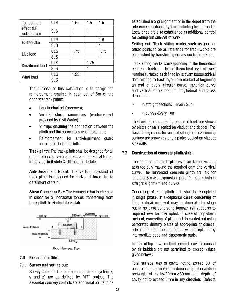
The lateral clearance between running rail and derailment guard should be 250-300mm. Derailment guard should not be lower than 50mm from running rail top. The wheels of derailed vehicle under crush load moving on maximum speed should be retained on viaduct. Damage to track and supporting structure should be minimum.
2.3.3 Rail fastenings:
The Components of rail fastening system:
9 Resilient pad
9 Insulating elements
9 Rail pad
9 Clips and screws
9 Inserts
9 Load distribution plates
9 Anchor bolts, struts.
25
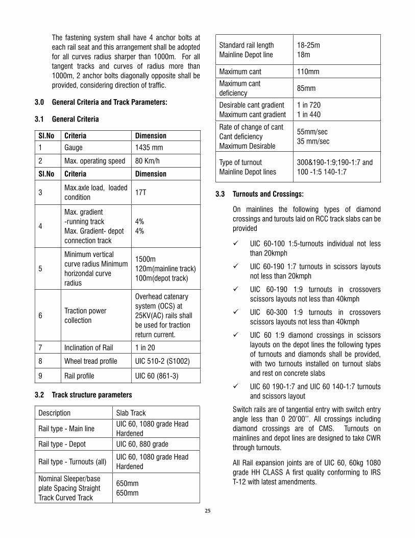
The fastening system shall have 4 anchor bolts at each rail seat and this arrangement shall be adopted for all curves radius sharper than 1000m. For all tangent tracks and curves of radius more than 1000m, 2 anchor bolts diagonally opposite shall be provided, considering direction of traffic.
Rate of change of cantCant deficiency Maximum Desirable
55mm/sec35 mm/sec
Type of turnout Mainline Depot lines
300&190-1:9;190-1:7 and 100 -1:5 140-1:7
3.3 Turnouts and Crossings:
On mainlines the following types of diamond crossings and turouts laid on RCC track slabs can be provided
9 UIC 60-100 1:5-turnouts individual not less than 20kmph
9 UIC 60-190 1:7 turnouts in scissors layouts not less than 20kmph
9 UIC 60-190 1:9 turnouts in crossovers scissors layouts not less than 40kmph
9 UIC 60-300 1:9 turnouts in crossovers scissors layouts not less than 40kmph
9 UIC 60 1:9 diamond crossings in scissors layouts on the depot lines the following types of turnouts and diamonds shall be provided, with two turnouts installed on turnout slabs and rest on concrete slabs
9 UIC 60 190-1:7 and UIC 60 140-1:7 turnouts and scissors layout
Switch rails are of tangential entry with switch entry angle less than 0 20’00’’. All crossings including diamond crossings are of CMS. Turnouts on mainlines and depot lines are designed to take CWR through turnouts.
All Rail expansion joints are of UIC 60, 60kg 1080 grade HH CLASS A first quality conforming to IRS T-12 with latest amendments.
26
3.3.1 Buffer stops:
Track which ends in workshops, inspection bays are fitted with wheel stops compatible with wheel diameter which stops empty car or car travelling at 5 kmph. Ends of washing lines, stabling lines, test track, shunting neck and delivery track on depot shall be with friction buffer stops. In viaduct and underground stations track ends on friction sliding buffer stops with impact absorption material on the face.
9 252 T mass for an empty 6 car train
9 408T for fully loaded 6 car train
The stopping performance of empty train on viaduct (depot/mainline transfer) – stop from 15km/h in 15m without damage to train and buffer; stop from 25km/h in 15m regardless of damage to the train and buffer.
The stopping performance of fully loaded train on mainlines stations-
9 Stop from 10km/h in 15m without damage to train and buffer;
9 Stop from 25km/h in 15m regardless of damage to the train and buffer.
4.0 Loads and Requirements:
Each component of the structure shall be designed and checked for all possible combinations of applied loads and forces. They should resist effect of worst combinations.
4.1 Dead or Static Load :
Track Work: Load due to UIC rail and other fittings;
Track Bed : RCC blocks or precast slabs with inserts and fittings for ballast less tracks;
Other loads as per IRS and BIS.
4.2 Fatigue Loading:
The nominal loading for the design of members in accordance with fatigue requirements shall comprise trains with six individual cars each having four axles, axle loads and vehicle length will be supplied by rolling stock manufacturer.
Fatigue load histories should be evaluated to provide valid and representative design spectra, with stress histories analysed by the rain flow or equivalent method both in conjunction with the projected annual tonnages of rail traffic per track.
4.3 Dynamic Loading:
The static and fatigue loadings shall be multiplied by an appropriate dynamic load factor for design element considered.
Dynamic load factor is not considered for centrifugal, breaking and traction loads.
4.4 Longitudinal Loads:
Longitudinal loads from braking and traction shall be a minimum of 18% live load per track. When a structure carries two tracks both tracks will be considered to be occupied simultaneously. Traction force is considered to act on one track and braking forces to act on another track, with both forces acting in same direction simultaneously to produce worst loading condition in the rails and supporting elements.
Longitudinal forces acting on the track is considered to be dispersed through the track before being transmitted to the sub-structure. This shall be calculated based on IRS bridge rules, IS and other relevant codes deemed applicable (ACI. AASHTO, ASCI, BSI-EN).
Forces shall be calculated for the case of interaction between CWR and a concrete structural support resulting from temperature differentials of rail and concrete base.
Longitudinal forces shall consider effect on stability and safety of the applied axle loading arising from broken rail on ballast less track.
4.5 Centrifugal loads:
Centrifugal loads acting transversely to line of rail movement due to track curvature and rail cant are to be considered in design. The effects are to be considered for various track, track bed, structural elements and interface locations.
27
4.6 Train derailment load:
Impact on adjacent structures due to derailment shall be considered at relevant locations for appropriate quanta of impact loads. The adjacent structures are to be protected by direct means (strengthening) or indirect means (repositioning rail alignment or providing barriers) to ensure these structures are still functional after an impact occurs.
4.7 Wind Load:
Wind loading primarily affects elements of underground structures such as vent-shafts, entrance ways, cooling towers and pedestrian bridges. Also it’s a factor on temporary structures during construction. IS 875 part-III is used to determine design wind load.
4.8 Temperature Load:
Forces arise due to thermal gradient within a structural element, which may be from external sources or in fresh concrete due to internal heat of hydration during curing. ‘Lock in’ forces from temperature effects due to differential curing of concrete remains as permanent load, for which also elements must be designed.
Temporary works with structural steel bracing elements may also suffer adverse effects from thermal strains.
4.9 Seismic Load:
Bridge rules and IS 1893-2002 Part-I codal reference is used to evaluate seismic loads. The structure can be evaluated by static lateral force analysis approach or dynamic lateral force (response spectra) approach. Seismic design using response spectra requires adopting more onerous loading from strong motion data from recent seismic events in Chennai region or suitably factored for intensity with similar geological conditions. The effects of load changes due to liquefaction must be accounted in design were appropriate.
4.10 Erection Load:
Weight of all temporary and permanent materials together with all other forces and effects which can operate on any part of the structure during erection should be taken into account in design as lock in stresses.
4.11 Shrinkage and Creep Load:
Differential creep caused by interface shear transfer mechanisms and residual shrinkage effects from staged casting of concrete elements.
4.12 Noise and vibration mitigation:
Track structure and fastenings are designed such as to minimise the noise generated by the moving train on the track and limited as per EN ISO 3095(2005)-Accoustic measurement of noise by rail bound vehicles .
5.0 Ground-Borne Vibration Criteria:
Track structure and fastenings are designed such as to minimise the ground-borne vibration generated by moving trains on track. The vibrations levels are restricted such as not to cause discomfort to the human beings in adjacent vicinity. Appropriate vibration mitigation arrangements like elastomeric bearings below the slab track are proposed to be adopted at sensitive locations like hospitals, existing main line railway tracks to limit vibration to tolerable levels. Tentatively 7 such locations are identified.
6.0 Design Methodology of Track Plinth:
Figure - Typical cross section of track plinth in straight
The following 3 Load combinations (LC1, LC2, LC3) are considered for realistic design, since there are no codal provision for track plinth design:
LoadsLimit state
Load factorsLC1 LC2 LC3
Dead LoadULS 1.4 1.4 1.4SLS 1 1 1
Superimposed dead load
ULS 2 2 2SLS 1.2 1.2 1.2
28
Temperature effect (LR, radial force)
ULS 1.5 1.5 1.5
SLS 1 1 1
EarthquakeULS 1.6SLS 1
Live loadULS 1.75 1.75SLS 1 1
Derailment loadULS 1.75 SLS 1
Wind loadULS 1.25 SLS 1
The purpose of this calculation is to design the reinforcement required in each set of 5m of the concrete track plinth:
• Longitudinal reinforcement;
• Vertical shear connectors (reinforcement provided by Civil Works) ;
• Stirrups ensuring the connection between the plinth and the connectors when required ;
• Reinforcement for anti-derailment guard forming part of the plinth.
Track plinth: The track plinth shall be designed for all combinations of vertical loads and horizontal forces in Service limit state & Ultimate limit state.
Anti-Derailment Guard: The vertical up-stand of track plinth is designed for horizontal force due to derailment of train.
Shear Connector Bar: The connector bar is checked in shear for all horizontal forces transferring from track plinth to viaduct deck slab.
Figure - Transversal Shape
7.0 Execution in Site:
7.1. Survey and setting out:
Survey consols: The reference coordinate system(x, y and z) are as defined by MRT project. The secondary survey controls are additional points to be
established along alignment or in the depot from the reference coordinate system including bench marks. Local grids are also established as additional control for setting out sub-set of work.
Setting out: Track sitting marks such as grid or offset points to be as reference for track works are established by transferring survey control markers.
Track sitting marks corresponding to the theoretical centre of track and to the theoretical level of track running surfaces as defined by relevant topographical data relating to track layout are marked at beginning an end of every circular curve, transition curve and vertical curve both in longitudinal and cross directions.
9 In straight sections – Every 25m
9 In curves-Every 10m
The track sitting marks for centre of track are shown by plates or nails sealed on viaduct and depots. The track sitting marks for vertical sitting of track running surface are shown by angle plates sealed on viaduct sidewalls.
7.2 Construction of concrete plinth/slab:
The reinforced concrete plinth/slab are laid on viaduct at grade duly making the required cant and vertical curve. The reinforced concrete plinth are laid for length of 5m with expansion gap of 0.1-0.2m both in straight alignment and curves.
Concreting of each plinth slab shall be completed in single phase. In exceptional cases concreting of integral derailment wall may be done at later stage but in no case concreting beneath rail supports to required level be interrupted. In case of top-down method, concreting of plinth slab is carried out using perforated dummy plates of appropriate thickness, after concrete attains strength it will be replaced by intermediate pads and elastomeric pads.
In case of top-down method, smooth cavities caused by air bubbles are not permitted to exceed values gives below :
Total surface area of cavity not to exceed 3% of base plate area, maximum dimensions of inscribing rectangle of cavity-20mm×30mm and depth of cavity not to exceed 5mm in any direction. Defects
29
within the limits are rectified by applying suitable epoxy based filler material and grinding the surface.
7.3 Installation of slab track form and concreting:
If elasomeric bearings are to be used for vibration mitigation the installation procedure is as follows :
Surface of tunnel is freed from debris and a protection layer of 100mm is placed over which elastomering bearing rest. The sleepers are leaded to the tunned from pallets using rubber tyred mobile crane with multiple sleeper lifting frame which holds sleeper at correct spacing. Timber gluts will be placed on elasomeric bearings parallel to track center line which supports sleeper ends. Reinforcement will be laid in front of sleeper which is to be place below the sleeper bottom chord. Timber will be removed at later stage when tracks are supported on temporary track supports. Using rail threader the rails are lifted on sleepers. Using coach screw machine screws and clips already placed on sleepers are tightened. Track supporting units of spindle bracket type are located at 1.95m c/c to adjust locally drainage and ducts. This will be cast into slab.
7.4 Stray current collection and earthing:
When expansion gap at embedded concrete occurs electrical discontinuity is maintained using cable straps attached to copper riser plates one plate on each side of the gap.
7.5 Final preparation:
Track geometry is corrected for horizontal and vertical alignment. A stop end shutter at a distance of 10m for straight and 20m for curves before the end of already adjusted track for readjusting the last 10m or 20m with next track section concreting. Similar procedure adopted for turnouts also.
7.6 Delivering concrete to the pour:
Concrete will be delivered by a pump beneath viaduct which directly or through secondary system delivers to track slab. Inside tunnels the concrete is delivered through mixer trucks on truck through pump and piping system. Samples will be collected for casting test cubes. The cycle time of concrete not to exceed 80minutes.
7.7 Pouring concrete:
On tangent track concrete pour starts from track centre until it flows below sleeper and both ends, later the sides of slab will be topped. On super elevated track concrete is poured on low side below the sleeper, proceed to centre then on to low side of next sleeper and finally on higher side to make concrete stable. Care should be taken to avoid voids, consolidation using vibrators is done to remove air and ensure horizontal flow. Incase of catastrophical failure concrete will be washed out. The concrete is initially levelled using screed rail or wooden flat and then using steel trowel finish.
7.8 Cleanup and completion:
After initially setting of concrete vertical spindles loosened for ½ to 1turn, in following shifts the spindles are removed, cleaned with mould oil. The holes left due to track supports are filled with mortar.
8.0 Rail welding and Destressing:
8.1 Rail joints:
All rail joints throughout main lines, depot lines including turnouts except at locations not authorized by employers representative are welded using mobile flash butt welding. In exceptional cases with approval of employers representative AT welding is done. Clearance of weld between two joints is minimum 18m for main lines and 13m for depot lines.
Fish plate joints are used for depot lines were welding not feasible. All fish plate nuts are provided with nuts with spring washer. Glued insulated rail joints are manufactured using minimum 6m long rail lengths, except in turnout zone the position of glued insulated joint with respect to weld in approach track are at a minimum distance of 4m.
8.2 Rail temperatures:
Measured using adequate number of embedded type rail thermometer as instructed by employers representative. During conversion of LWR to CWR, stress free temperature lies in tm-5 to tm+10, where tm- mean rail temperature 37oc.
30
8.3 Flash butt welding quality control:
Three samples for flash butt weld are to be made for fatigue test. If any weld fails cause should be identified and similar welds on rails should be removed. Rails
Sl.No Parameter Tolerance
Track tolerances shall comply with the following limits :
(i) Gauge (with reference to 1435 mm)
Maximum rate of variation over the prescribed track gauge *Slab track ±2 mm *Mean gauge per 200m for slab track (1435+1.5mm to (1435-1mm) *Standard deviation within a 200m Section Less than 1mm(ii) Maximum difference of any point in relation to the designed layout (vertical) *Slab track (-4mm)/(+4mm)(iii) Difference of any point in relation to the designed layout *(horizontal) Straight ±4 mm On straight and curve, deviation of measured versine over its designed value on a 20 m chord : (half overlapping) Sl.No Parameter Tolerance *Slab track ±2 mm(iv) On constant grade and vertical curves, Maximum deviation of measured versine over its
designed value on a20m chord (half over lapping)
*Slab track ±3 mm(v) Cant/Cross Level (to be measured at every 3m ) Straight track and curved track *Slab track ±1.5 mm (Deviation from designed value) Base plate to base plate (slab track) *Variation of cant/ cross level ±1 mm(vi) Twist: maximum value on a base of 3 m (slab track) *Straight and circular portion of curve 1mm/m *On transition portion of curve(over & above designed value) 0.5mm(Vii) Turnouts (slab track) *Stock rail joint (longitudinal location) ±15 mm *Nose to nose of Xing in crossovers *(Slab track) ±10 mm(viii) Flange way clearence at end of the switch planning (+5)mm /(-0 )mm *Switch toe opening (+1)mm(-0)mm
exceeding the end tolerance are not to be welded. After welding the rail end tolerance beyond limit is to be corrected without causing any damage, or the rail ends may be rewelded. Finishing of welds are to be
31
done by controlled profile grinding. Weld records are to maintained and submitted for every 1km.
8.4 Destressing:
The LWR shall be laid on rollers placed on sleeper rail table or metal base plates at maximum interval of 6m with additional side rollers on curves. Stress is relieved by hitting with wooden mallets on sides of rail head.
9.0 Track tolerances :
The completed track geometry shall be measured for gauge, alignment, cross level, twist, unevenness :
Sl.No Parameter Tolerance *Switch toe squareness 5mm
*Deviation of measured versine over its designed value of switches,lead track (measured on 6 metre half overlapping chord)
±2 mm
(iX) Sleeper/Base plate *Spacing(from designed spacing) ±5 mm
*Sleeper/base plate/perpendicularity to rail centre line(out of square) 5mm
(X) Rail joint squareness across the track *(fishplated) 10mm
(Xi) Tighten-up of fastening componentsDesign torque +/- 5% wherever applicable for bolted fastening system
10.0 Conclusion:
Some ideas in the design of track structure in elevated corridors and underground corridors are discussed in this paper. Slab is used to support the rails with or without use of sleepers, suitable anchorage with the base supporting systems are designed. Load combinations with worst realistic possible combinations are used to arrive the design loads, and designed by basic structural design concepts of slab. The only difficulty seams to be non availability of unique code for complete design and analysis, due to which various codes pertaining to each loads, analysis of each element has been used.
4 Million People Across Pacific to Suffer from Food,
Clean Water Scarcity Due to El Nino
More than 4 million people across the Pacific are predicted to suffer from food or clean water scarcity due to the current El Nino. People are suffering from a prolonged drought in the Chimbu province in Papua New Guinea, which caused sudden and severe fronts in highlands and killed almost all crops. A state of emergency has been declared in two other highland provinces in the country, and many areas would possibly run out of food in two or three months. According to reports in the coming months, there will be more rain, floods, and higher sea levels in countries near the equator due to El Nino and low-lying islands are already experiencing the impacts of climate change.
Initiative Taken by NFR to Mitigate the Mortality of Wild Elephant on BG-III Section of Alipurduar Division
By Jeetendra Kumar *
Tapan Kumar Das**
1.0 Introduction
Indian Railways is one of the largest railway networks in the world. Out of about 65000 Route Kms of IR, about 1593 Route Kms of railway track passes through Reserve Forests in the country. Some of these lines pass through wildlife habitats. In the country, elephants are distributed in four population units, viz., North- Western (Uttrakhand & UP), North Bengal (Dooars of West Bengal), North –East (Assam, Arunachal, and Meghalaya), East Central (Jharkhand, Orissa) and South (Tamil Nadu, Kerala, and Karnataka).
In the jurisdiction of Alipurduar Division of Northeast Frontier Railway about 148 Route Kms of track passes through Buxa Tiger Reserve, Jaldapara sanctuary, Chapramari sanctuary and Mahananda sanctuary falling in the Siliguri – Mal- Samuktala section over APDJ Division of NFR.
There have been a number of cases of elephant mortalities due to train hits on Railway Track. The largest numbers of incidents of elephant fatalities have taken place in the North Bengal forest area falling in the jurisdiction of Alipurduar Division of Northeast Frontier Railway. During the period 2007 – 2015, total 89 cases of elephant deaths due to train hits have been reported in India, out of which 42 cases are of APDJ Division.
2.0 General Information on APDJ- SGUJ Section of APDJ Division
• Section having Elephant Zone of Alipurduar Division.
a) Year of Commissioning of this section : 1952, Initially MG track, Subsequently converted to BG in 2002.
b) Siliguri Jn. - Alipurduar Jn. section : [KM 9/0 (SGUJ-GLMA) to 168/2 (APDJ)] also known as BG-III section.
*XEN/CON/NJP/NFR** ADEN/W/GHY/NFR
Integrated Course No. 15104
IRICEN JOURNAL OF CIVIL ENGINEERING
}
33
c) The Railway track passes through four Wild Life Sanctuary (Mahananda, Chapramari, Jaldapara and Buxa Tiger Reserve ).
• Population of Wildlife in North Bengal
(1) Elephants Population:
Census Year Population
1992 186
1998 230 – 250
2000 292
2003 280
2005 300 – 350
2008 350
2010 550 (plus)
2013 700 (Approx.)*
(2) Rhino Population:
Census Year Population
2013 200 (Approx.)*
(3) In addition, there are other wild animals like Tiger, Leopard, Bison, etc. in the forests of this area*.
Note : * as intimated by CCF/Siliguri in writing
• Human – Elephant Conflicts
People killed & property damaged by elephants & compensation paid in North Bengal:
Year
Persons
Killed
(No.)
Persons
injured
(No.)
Crops
Damaged
(Hectare)
Huts/
Houses
Damaged
(No.)
Compensation Paid (` In Lacs)
For
Persons
Killed &
injured
For Crops
Damaged
For Huts/
Houses
Damaged
Total
2010-
1156 341 1342.176 3207 72.3 62.78 39.82 174.9
2011-
1245 128 2563.92 2667 29.79 63.74 29.07 122.6
2012-
1352 96 2358.988 2538 43.1 116.1 45.08 204.28
N.B. - Based on the information furnished by CCF Wildlife (Headquarters),
West Bengal
• Summary of Elephant dashing cases over APDJ Division
(ii) Goods Train:- [Loco: WDG4, Load = 59 BOXN(L)]
SPEED
(Kmph)
EBD (Meters) On different gradients
-150 -200 -300 -400 -500Level
(1000)500 400 300 200 150
75 845 809 776 760 751 717 717 678 665 642 621
70 752 720 690 676 668 637 637 602 592 571 552
65 665 636 610 597 590 562 562 531 522 504 486
60 582 557 534 523 516 492 492 465 456 440 425
55 505 483 462 453 447 426 426 402 394 380 367
50 432 413 395 387 382 364 364 343 337 324 313
45 365 349 333 326 322 306 306 288 283 272 262
40 303 289 276 270 266 253 253 238 233 224 216
35 246 234 223 218 215 204 204 192 188 180 173
30 194 184 176 171 169 160 160 150 147 141 135
g. Limitation of visibility for Loco Pilots due to –
• Loco design (long-hood forward drive impairing visibility)
• Curvatures (impairing visibility)
h. Limitation of speed restriction due to –
• Gradient (results in stalling)
• Curvatures (result in stalling & impairing visibility)
• Demand for more trains (throughput) & higher speed
• Demand for punctuality
2.
36
4.0 Measures Taken to Prevent Dashing of wild elephants with Trains
4.1 Compliance on “Expert Committee Recommendations” & “General Adviseries”
a. Expert Committee:- Committee of Dr. Sushant Chowdhury, Scientist, Wildlife Institute, Dehradun; Shri S.S. Bisht, I.G. Forest & Director (PE), MoEF and Shri Rajesh Tripathi, Director Works, MoR, Railway Board who submitted the recommendations based on their inspection from 2nd to 4th May/2001.Based on their recommendations, PIL bearing WP No. 13220(W) of 2000 between WWF For Nature India & Others Versus UOI & Others in Calcutta High Court was disposed off on 03-10-2002 and operation of SGUJ – APDJ BG line after MG to BG conversion was allowed.
b. General Adviseries:- General advisories issued by MoR and MoEF based on meeting held on 04.09.2009, circulated by Railway Board vide Letter No.2007/TT-IV/9/8 dated 30.03.2010.
1. Clearance of vegetation on the side of railway track
This is being done regularly in all the identified elephant corridors of this Division within Railway area.Special drive is launched for additional clearance of vegetation on turnings, permission for which is taken from Forest Deptt.
2. Underpasses/Overpasses / Ramps across the Railway track to allow the elephants to escape
• Four works were identified in the year 2010 in the Alipurduar- Siliguri section, after joint survey by Railway and Forest deptt. (West Bengal) at an estimated cost of `7.27 crores to be executed by Railways on deposit terms. However, Ministry of Environment and
Forest, Govt. of India agreed for 3 works only at a cost of ` 2.42 crores and allocated ` 1.93 crores during the year 2010-11, vide Ministry of Environment and Forest’s letter No. 1-12/2009-(PE) dated 15.11.2010. An amount of ` 1.93 crores has been received from Deptt. of Forest, Govt. of West Bengal on 09.11.2011 against ` 2.42 crores after considerable follow up.
• Necessary Contracts have been awarded during January’2012 for executing the three works and the status of progress is as under : -
(i) Construction of Passes in Chapramari Wild Life Sanctuary:
• (Construction of passes at Km 66/2-3 (LH), 67/3-4(LH), 67/8-9 (Both side), 67/9-68/0 (Both side) & 68/3-4 (Both side) as well as closing passage at Km 67/4-5 (LH side) between station Chalsa – Nagrakata.
• Present status – all the works has been completed in March 2013).
(ii) Construction of Ramp in Jaldapara Wild Life Sanctuary:
• (In Jaldapara Sanctuary, 15 meters wide 02 nos. ramps at Km. 128/8-9 have been provided on each side of railway track to facilitate the move of Elephants between the Northern and Southern parts of the Sanctuary.)
• The work is completed in Feb/2013.
37
(iii) Construction of Girder Bridge & Fencing in Mahananda Wild Life anctuary:
• Forest department has given decision on the issue of modified plan / location on spot on 12-01-13 during joint inspection in presence of APCCF of West Bengal.
• Work has two parts: (a) construction of one girder bridge at Km 24/6-7 in place of earlier location of Km 24/4-5 (Gulma end of cutting) (b) erection of fencing of about 250m length on both side of track between sevok end of cutting (Km 25/9-26/0) and existing girder bridge No. 46 (Km 26/2-3).
• Purpose :- To prevent wild elephants entering into deep cutting of the railway track, getting trapped & meeting with a train accident. (Elephants do not walk on Girder bridges).
• Work is completed.
(iv) Signage boards to pre-warn the train drivers
• Signage boards have been provided at all the identified elephant corridors to pre-warn the Loco Pilots at the locations decided by Forest Department. Crew is being regularly reminded & new crews are being cautioned on wildlife aspects.
(v) Sensitizing of train drivers/ guard/ station masters
• It is being regularly done. So far 325 LPs/ALPs, 85 Guards, 95 Station Masters, 16 SSEs/P.Way, 06 TIs, 22 LIs, 5 Safety Counselors and 08 Trackman (Total = 562 Nos.) have been covered. LPs/ALPs are sensitized to observe Permanent and Temporary speed restriction rigidly which have been imposed to prevent mortality of wild elephants over the Railway tracks. This program has been included in the syllabus of refresher courses for crew.
• Posters have been displayed in Crew Lobbies to sensitize running staff to save wildlife.
(vi) Engagement of elephant trackers of Forest Deptt and communication with Station Master
• Elephant trackers have been provided by Forest Deptt in BTR only. However, we are receiving information from respective Forest Ranger almost daily about presence of elephant herds near the Railway track. Moreover, information is received through Railway staff (Loco Pilot, Asstt Loco Pilot, Guard, Station Master, Trackman, Patrolman, L.C. Gateman etc.) regularly regarding the presence of elephant observed by them in the section.
• 25 Watt VHF set with frequency of Forest Deptt. has been commissioned at Rajabhatkhawa and Kalchini and Hasimara station on 26.03.2013, 02.04.2013 and 10.06.2013 respectively.
• Forest Deptt staff (one each in two shifts) are posted in APDJ Control Office from 17.00 hrs to 05.00 hrs who are supposed to get pre-intimations of Elephant movement from field & advice Control Office to take necessary action.
• On received of information, Caution order is being issued to the Loco Pilots regularly by the concerned Station Master to go with cautious speed with sharp look out for elephant herds and be ready to stop the train in emergency.
• Mobile No.9434724204 has been provided at BG-III Board (Samuktala-Siliguri section) of APDJ Control office exclusively for giving information regarding wild elephant movement on/near the railway track based on which subsequent precautionary measures are taken by the Control office.
38
(vii)To keep Railway track free from food waste that attracts elephants.
• Pantry Car staffs of the train passing through the elephant corridors area are being sensitized on this issue.
• Besides, public announcement at Alipurduar Jn. has been started to motivate passengers not to throw any eatable / leftovers on/ near the railway track as elephants and other wild animals get lured to the track and get involved with the accident. Others stations up to SGUJ/ NJP will be covered soon.
• Dustbins for collection of such materials have been provided at major stations en-route.
(viii) Rail Fencing in BTR (HSA-KCF)
• Rail fencing at Km.139/3-140/4 (1 Km) between HSA-KCF has been erected along left side of the track during Gauge Conversion in the year, 2003
Further Rail fencing proposed by MOEF at identified locations could not be undertaken due to reservation of Forest Department against rail fencing with reasons such as –
(i) Restrict movement of wild elephants.
(ii) More human – Elephant conflict
(ii) Disturbance to local public, property etc.
(ix) Restricting Speed of trains in vulnerable sections:
• All speed restrictions advised by Forest Deptt are being meticulously complied.
• Details of Temporary & Permanent Speed Restrictions imposed over APDJ Division on wild elephant account are furnished below:
(I) PERMANENT SPEED RESTRICTION
Sl. Date
implemented Section KM
Speed
limit Time
Total
KM
1 01.07.2008 GLMA-SVQ 16/5 –
27/0
50
Kmph
00.00 –
24.00 10.50
2 01.07.2008 CLD – NKB 65/8 –
68/9
50
Kmph
00.00 –
24.00 3.10
3 01.07.2008 MDT –
HAS
128/1 –
130/8
50
Kmph
00.00 –
24.00 2.70
4 01.07.2008 HSA – KCF 140/2 –
141/3
50
Kmph
00.00 –
24.00 1.10
Total Km 17.40
(II) Temporary speed restriction
SL Section KM Speed limit Time Total
KM
1 GLMA-
BRQ
16/0 –
16/5
50 Kmph, or lower if
required to stop short of
obstruction if any.
17.00 –
05.00 0.5
2 SVQ-
BRQ
27/0-
34/2
50 Kmph, or l lower if
required to stop short of
obstruction if any.
17.00 –
05.00 7.2
2 CRX –
DLO
81/6 –
100/6
50 Kmph, or lower if
required to stop short of
obstruction if any.
17.00 –
05.00 19.0
3 MJE
-HSA
114/0 –
128/1
50 Kmph, or lower if
required to stop short of
obstruction if any.
17.00 –
05.00 14.1
4 HSA-
KCF
130/8-
140/2
50 Kmph, or lower if
required to stop short of
obstruction if any
17.00 –
05.00 9.4
5 MDT-
RVK
141/3-
159/0
50 Kmph, or lower if
required to stop short of
obstruction if any.
17.00 –
05.00 17.7
6 RVK-
APDJ
164/0-
168/0
50 Kmph, or lower if
required to stop short of
obstruction if any.
17.00 –
05.00 4.0
Total Km - 71.9
39
(III) In addition round the clock speed restriction is imposed in the following section and kilometer due to heavy influx of elephant over BTR (in March 2013).
SL Date Section KMSpeed/
CauseTime
Total
KM
1. 05.03.13RVK –
APDJ
159/0-
164/050 KMPH
00.00 –
24.005 KM
(IV) Addl restrictions imposed as per Hon’ble SC order on 02-09-2014:
1 GLMA-BRQ
22/9 -23/0 **
25 Kmph for all Goods train
including L/E round the clock
00.00 – 24.00
0.1
2 SVQ-BRQ
30/8 -33/0 **
00.00 – 24.00
2.2
3 NMZ-CLD
59/4 - 64/9 00.00 – 24.00
5.5
4 RVK-APDJ
157/0- 168/0 **
00.00 – 24.00
11.0
** Common/overlapping with PSR or TSR above Total Km
18.8
Grand Total = 17.4 +71.9 + 5 + 5.5= 99.8 km
In addition to Permanent and Temporary speed restriction, on received of information, regarding movement of elephants, caution order is being issued to the Loco Pilots regularly by the concerned Station Master to go with cautious speed with sharp look out.
5.0 Additional Measures
(1) Further Initiatives taken by the Division to eliminate Elephant mortalities due to Train hits
• Speed Rader Guns have been purchased to monitor speed of loco en-route & check the cases of over-speeding if any.
• Special Drive of Inspections by Officers/Supervisors to check alertness of LP/ALP and speed is being launched from time to time.
6.0 Modern Technology Based Long-Term Solutions
• E-Surveillance Camera: A project of 24x7 infrared / thermal intelligent camera with feed to a Control Room has been successful in Corbett National Park. Its efficacy can be tried at other locations (Pending on MoEF & Rly. Bd).
• Wireless animal detection system: It is a developmental research project of IIT/Delhi and funded by Deptt of Science & Technology and MoR.
• Radio Collaring of Elephants: It needs further investigation. There are apprehensions of elephant mortalities while tranquilizing the elephants during radio collaring (Pending on MoEF).
• RFID Tagging of Elephants: It needs further investigation. The range of the RFID tags has to be long enough to be picked up by the sensors. As of now the chips that are implanted on elephants have short life and very low range. Moreover, implantation of chips involves tranquilizing of elephants (Pending on MoEF).
• Solar Lighting along the railway track on vulnerable stretches with lights directed at right angles away from the track to deter the elephants from approaching the railway track at night. (Railway has no expertise of such installation for this purpose. Forest deptt is likely to take up this project on experimental basis.)
• Ultrasonic Elephant Repellent System (ERS): It is based on the principle that ultrasonic sound of a particular frequency repels elephants. The device uses variable ultrasonic frequency to repel animals in the given area automatically. (Its effectiveness is yet to be established.)
7. 0 Case in Supreme Court
• WP (Civil) No. 107 of 2013
• Shakti Prasad Nayak V/s UOI & Ors
• Demand / Court’s directive in order dated 10-12-2013:
– (a) To reduce the speed limit of trains passing through dense forests and in case a speed limit is not followed, appropriate action against the erring drivers & officials concerned.
– (b) Railways to take steps to discontinue movement of goods trains at night between Siliguri to Alipurduar.
– (c) Divert fast moving & night trains through alternate NJP-FLK Route
• Order dated 21-01-2014:
As per Supreme Court’s order dated 21-01-2014
40
MoEF and Railway to examine measures taken in other states including Karnataka (where no elephant casualty took place in 2013) and submit (during next hearing after 2 weeks) detailed suggestions & steps to be taken to avoid untoward incident for protecting wildlife.
• Order dated 02-09-2014 (Latest): Speed restriction of 25 KMPH as suggested by the MoEF vide letter dated 17-10-2007 at 4 locations:
1GLMA-
BRQ22/9 -23/0 **
25 Kmph
for all
Goods train
including
L/E round
the clock
00.00 – 24.00 0.1
2 SVQ-BRQ 30/8 -33/0 ** 00.00 – 24.00 2.2
3 NMZ-CLD 59/4 - 64/9 00.00 – 24.00 5.5
4 RVK-APDJ157/0- 168/0
**00.00 – 24.00 11.0
** Common/overlapping with PSR or TSR above Total Km 18.8
8.0 Comments
Let us again we see the summary of Elephant dashing cases over APDJ Division
From the above table it is clear that despite various initiatives taken by NFR on APDJ Division with the help of Forest Department and others the mortality of wild elephant could not stopped. The worse situation was in the year 2010 & 2013.
It means a lot of measures are still have to be taken by Railway, Forest department, NGOs and local people for the safe passage of wild elephants over the Railway track with minimum imposed speed restrictions to trains. The maximum number of death of elephants happened on outside their identified corridors of track passing. In our view the best solution, although it is difficult on ground, is that we must ensure that their habitats are free of encroachment along with the availability of sufficient foods for them inside the forest itself so that they can freely live in their homes and can move freely only through their identified corridors over the track. For watching their movement near the track the latest technology should be used. Otherwise, Railway have to compromise a lot like speed restriction, minimizing of night trains especially of goods and other huge indirect losses.
We hope with continuous sincere efforts the Rail and Elephant both can survive without harming to each other.
List of Elephant Killed on Railway tracks in North Bengal (SiliguriJn. To AlipurduarJn.)
1616
14
12
11
10
8
6
5
4 4 4 4
3 33
2 2222 2
11111111111
000000000000000000
1974
1975
1976
1977
1978
1979
1980
1981
1982
1983
1984
1985
1986
1987
1988
1989
1990
1991
1992
1993
1994
1995
1996
1997
1998
1999
2000
2001
2002
2003
2004
2005
2006
2007
2008
2009
2010
2011
2012
2013
2014
2015
Conversion f rom MG to BG on 20-11-03
41
Ground Improvement Using Pre-Fabricated Vertical Drains Proposed Construction of New BG Line between Nagapattinam and
Tiruthuraipundi from Ch:3000 to 35000 m. Southern Railway By
Y. Thimmaiah* K. Ethiraj**
1.0 Introduction:
The project report is related to the construction of New BG line between Nagapattainam and Tiruthuraipundi (via) Tirukkuvalai which is diverting from the existing BG line of Nagapattinam and Velankanni Section at ch:3/0. The existing sub soil is soft clay having very low SBC values and its strength has to be improved during forming of bank. It was proposed to adopt pre-loading technique using PVD as a new concept. At present the stretch from ch:13000 to 18000 m is being tackled with PVD. The design for PVD for this location has been made by NIT/TPJ. The soil investigation report from chainage 13000 to 18000m is considered for PVD design. The work is getting delayed due to non availability of dredged sand and adequate quantity of filling earth. The PVDs has been installed about a length of 500 m and sand filled duly followed by Design by NIT/Trichy and proof checked by IIT/Chennai. In the interest of project work and interpretation of results, the settlement details of some other section i.e Doubling of track between Mulanthuruthy and Kuruppanthara, of construction, Southern Raiwlay have been compared for this new concept of application.
* AXEN/CN/TVR, S.Rly** AXEN/GC/MSC, S.Rly.
2.0 Site conditions:
Evaluation of the soil investigation report shows the SPT N values low up to investigation depth. The bore holes were terminated at a depth of about 8 to 13m. The unconfined compressive strength of the sample is low indicating that the CLAY is soft and leads to large deformations under the embankment loads. Therefore it is essential to stabilize the ground to mitigate settlement. The ground is proposed to treat with prefabricated vertical drains. More over if sufficient time is available to complete the work, PVD works out to be economical. Detailed design for spacing of PVD, estimated time required for consolidation is made for the above work.
Use of PVD in the present site condition is a viable option since the sufficient time is available for consolidation. The main aspect in design is the estimation of spacing and stability of the system when the surcharge is placed or the embankment is constructed. Stage construction is proposed since the height of the embankment is high to avoid bearing capacity failure.
CH:13000 (TERMINATION DEPTH :8m)
Depth, m
Layer
thickness
, m
SPT N valueIS
Classification
NMC
(%)
Density
kN/m3
Liquid
Limit
(%)
Plastic
Limit
(%)
Plasticity
Index (%)
UCC
Test kN/
m2
Triaxial Shear Test Cv.
Cm2/
Year
Cc
Void
Ratio,
e0Min. Max.
Cohesion
kN/m2
Angle
Ø,deg
0 to 1.5 1.5 4 CI 45 11.7 44 20 24 35 39* 0 - - -
1.5 to 3 1.5 6 CI 21 13 49 25 24 42 47* 0 0.4394 0.27 1.03
3 to 4.5 1.5 5 CI 42 13 43 23 20 46 52* 0 - -
4.5 to 6 1.5 8 CI 52 13.1 48 21 27 71 76* 0 - -
6 to 8 2 9 CI - - - -
Bore Log Details
IRICEN JOURNAL OF CIVIL ENGINEERING
Integrated Course No. 15104}
42
CH:14000 (TERMINATION DEPTH :10m)
Depth,m
Layer
thickness
, m
SPT N valueIS
Classification
NMC
(%)
Density
kN/m3
Liquid
Limit(%)
Plastic
Limit
(%)
Plasticity
Index
(%)
UCC
Test kN/
m2
Triaxial Shear TestCv.
Cm2/
Year
Cc
Void
Ratio,
e0Min. Max.
Cohesion
kN/m2
Angle
Ø,deg
0 to 1.5 1.5 6 CI 51 12.1 48 20 28 50 55* 0 - -
1.5 to 3 1.5 4 CI 62.7 11.9 46 25 21 55 60* 0 0.0508 0.199 1.14
Ch. Cv(cm2/min) Cv(cm2/Sec) Cv (m2/day) Cv(avg) (cm2/day) Cc Cc (Max.)
13000 0.0087 1.45E-04 1.25E-03
1.07E-03
0.265
0.26513250 0.00854 1.42E-04 1.23E-03 0.265
13500 0.0074 1.23E-04 1.07E-03 0.199
13750 0.009 1.50E-04 1.30E-03 0.1990
14000 0.0008 1.33E-05 1.15E-04
1.15E-03
0.199
0.332
14250 0.0087 1.45E-04 1.25E-03 0.332
14500 0.00376 6.27E-05 5.41E-04 0.190
14750 0.00676 1.13E-04 9.73E-04 0.190
15000 0.0189 3.15E-04 2.72E-03 0.199
15200 0.00852 1.42E-04 1.23E-03
2.19E-03
0.259
0.25915500 0.035 5.83E-04 5.04E-03 0.193
15750 0.00816 1.36E-04 1.18E-03 0.190
16000 0.00896 1.49E-04 1.29E-03 0.190
16250 0.00792 1.32E-04 1.14E-03
9.50E-04
0.298
0.29816500 0.00693 1.16E-04 9.98E-04 0.132
16750 0.0046 7.67E-05 6.62E-04 0.178
17000 0.00693 1.16E-04 9.98E-04 0.132
17250 0.0053 8.83E-05 7.63E-04
2.75E-03
0.178
0.22317750 0.0219 3.65E-04 3.15E-03 0.223
18000 0.03006 5.01E-04 4.33E-03 0.199
44
Soil Test report of Voids Ratio
Ch. e0 e0 (Max)Max , Formation
Height (m)
13000 1.03
1.03 5.544=5.6
13250 1.03
13500 0.38
13750 0.83
14000 1.14
1.14 6.149=6.2
14250 0.75
14500 0.83
14750 0.83
15000 0.50
15200 0.54
0.88 6.486=6.5
15500 052
15750 0.88
16000 0.83
16250 0.96
0.96 7.911=8.0
16500 0.76
16750 0.80
17000 0.76
17250 0.80
0.80 9.590=9.617750 0.57
18000 0.53
3.0 PVD Specification
Properties of PVD material used in the site:
Sl. No.
Test ParametersTest
ValueLlMITATION Test Method
1 Composite Drain
1 .Core Material – corrugated Synthetic Polyethylene
(i) Width (mm) 100 min 100+/-2
(ii) Thickness (mm) 4.6Min 3 to 4 (+/-0.25)
(iii)Discharge Capacity
(m3/sec)60 x 10-6 Min 50 x 10-6
ASTM-D 4716
(iv)Tensile Strength (kN)full width
2.5 Min 1.5ASTM-D
4595
(v)Elongation at 0.5 kN
load (%)4 Max 10
ASTM-D 4595
2Filter – Type – Non woven
Polypropylene fabric
(i)AOS(Apparent Opening Size)
micron<75 mic Max 80
ASTM-D 4751
(ii)Tensile Strength
(kN/m)5 Min 2
ASTM-D 4595
(iii) Permeability (m/s) 2 x 10⁻⁴ Min 1 x 10⁻⁴ASTM-D
4491
(iv)Tensile Strength at
Break (kN)2.7 Min 1.3
ASTM-D 4595
Assuming PVD of 100mm wide and 4.6 mm thickness , the expected time - degree of consolidation for different spacing is shown below. The time required to achieve a degree of consolidation for 90% for different spacing in triangular pattern is tabulated below. For staged construction, it is essential that at least 70% of consolidation shall be over before placing the subsequent stages. The estimated time required for 70% consolidation for different stages is shown below.
45
Time required for U = 70% and 90% for different spacings of PVD
Spacing, m
Time required in Days for degree of consolidation of
U = 70% U = 90%
1 53 103
1.2 83 160
1.5 140 270
1.8 213 415
4.0 Staged Construction
The undrained shear strength of the ground estimated based on the SPT in the soil investigation is about 25 kPa. The Height of embankment along the chainages is summerized is as follows:
The height of embankment is generally high ( >5 m). If the embankment is constructed in single stage, the embankment will fail due to lack of bearing capacity of the underlying soil. Hence it is recommended to go for staged construction. The maximum height recommended in first stage, second stage, third stage and final stage are 3.5 m, 3 m, 2 m and 1.5 m respectively. These values are arrived based on slope stability analysis. The thickness for each stage shall not exceed the recommended values.
Number of stages and thickness for different height of embankment
Sl.
No
Formation
height, M
Number
of stages
Thickness (m ) ofStage
1Stage 2 Stage 3 Stage 4
1 Up to 3.5 m 1<
3.5-- -- --
2 3.5 - 6.5 2 3.5Remaining
thickness-- --
3 6.5 - 8.5 3 3.5 3Remaining
thickness--
4 8.5 - 10 4 3.5 3 2Remaining
thickness
Estimated time required for different height of embankment (Construction at a slow phase)
PVD
Space
Formation
height, M
Number
of Stages
TIME (Days) required
Satge
1
Satge
2
Stage
3
Stage
4Total
1 m
Up to 3.5 m 1 103 --- --- --- 103
3.5-6.5 2 53 103 -- -- 156
6.5-8.5 3 53 53 103 -- 209
8.5-10 4 53 53 53 103 262
1.2 m
Up to 3.5 m 1 160 -- -- -- 160
3.5-6.5 2 83 160 -- -- 243
6.5-8.5 3 83 83 160 -- 326
8.5-10 4 83 83 83 160 409
1.5 m
Up to 3.5 m 1 270 -- -- -- 270
3.5-6.5 2 140 270 -- -- 410
6.5-8.5 3 140 140 270 -- 550
8.5-10 4 140 140 140 270 690
1.8 m
Up to 3.5 m 1 415 -- -- -- 415
3.5-6.5 2 213 415 -- -- 628
6.5-8.5 3 213 213 415 -- 841
8.5-10 4 213 213 213 415 1054
PVD material supplied at site (200 to 300m )
46
5.0 Construction Method:
(i) Remove the top soil up to a depth of 150 mm free from vegetation/roots etc. Construct 1.0 m thick of formation with using the standard formation soil. The width of formation shall extend beyond the toe of the embankment.
(ii) Devide the area in each of 25m longitudinal length and mark the points at a designed spacing of PVD to guide the PVD installation device.
(iii) Install the PVD in triangular pattern. The PVD shall project to a height of at least 200 mm above the ground. For height of embankment less than 3.5 m, one row of PVD shall extend beyond the edge of the embankment. For heights more than 3.5 m at least two rows of PVDs shall be installed beyond the edge of the embankments.
(iv) A coarse sand of (fines content less than 5% )blanket of 400 mm thick shall be provided above the ground as a filter media. The PVD should be embedded in to the blanket to at least 200 mm.
(v) The sand blanket shall be connected to side drains for proper drainage.
(vi) Construct the first stage to a maximum of 3.5 m height and allow for consolidation. The construction shall be proceeded at a slow pace. The recommended thickness of 20 cm per day, such that 3.5 m thickness is achieved in about 15-20 days. For heights less than 3.5 m, allow the embankment to consolidate for at least 90% consolidation.
(vii) For heights more than 3.5 m, the second stage shall be constructed only after the first stage reaches 70% consolidation.
(viii) Once the consolidation in stage 1 is over, subsequent stages shall be constructed. For heights more than 6 m a berm of at least 1 m shall be provided for stability.
(ix) The last stage shall be left till 90% degree of consolidation is achieved.
6.0 PVD Installation Pattern
The pettern of PVD installation is trianguilar method . The spacing is proposed between two PVD bands is 1.5 to 2.0 m according to the formation height and soil properties.
7.0 Surcharge Material
The soil of GW in classification is used for formation filling. The Plasticity Index of the soil is <5%. The slope of embankment is 2:1. The sand filled over PVD at a depth of 40 cm act as filter media below the filled earth to allow drain out the moisture came out from subsoil through the PVD bands due to cappillary action. The total height of Bank is 6.80 m . The PVDs are installed in triangular pattern upto toe of the bank and extra one row as per design considerations.
8.0 Instrumentation(settlement Gauges)
The predicted time for pre-loading depends on many factors in the field. Therefore, field instrumentation plays a major role in evaluating the progress of consolidation and to decide the degree of consolidation achieved. It is recommended to monitor settlements at every 250m stretch of the embankment. The settlements shall be recorded right from the installation stage every day for the first week and every week in the subsequent weeks so that no data is missed out. Complete details shall be recorded for interpretation.
Schematic section for embankment height less than or equal to
47
3.5m Schematic section for embankment height from 3.5m to 6.5m
9.0 Interpretation of Results
The work at above location is in progress and work is in slow progress due to non availability of adequate dredged sand and adequate filling earth for formation is also a one of the reason for delay in progress. As soon as the work is under progress the actual settlement takes place due to surcharge load will be observed duly installing the gauges below the earth fillinng.
In view of the above for the interpretation of results/achievement the consolidation observations with the settlement gauges of Doubling of track between Mulanthuruthy and Kuruppanthara, Kerala is shown below. The base soil at this location is also soft/clay soil for a length of 230 m. The work was executed with the same PVD bands and staged construction. The settlement gauges are installed and the levels of settlement gauge are taken at frequent intervals to observe the actual settement takes place during execution of work. It is observed that the cumulative settlement at the end of third month is 460 mm. The designed consolidated settlement is 790 mm.( with in 2 years of consolidation period)
The observed reults of settlement gauges
DateTime (Hrs)
RL of Fill
Change in Fill Ht
(m)
RL of Settlement
Gauge Top (m)
Observed Settlement
(mm)
Cumulative Settlement
(mm)Remarks
02.04.2014 16.00 2.485 0 3.810 0 0
06.04.2014 10.00 2.485 0 3.795 15 15
10.04.2014 10.00 2.485 0 3.785 10 25
15.04.2014 10.00 2.485 0 3.785 0 25
19.04.2014 10.00 2.485 0 3.785 0 25
23.04.2014 10.00 2.485 0 3.780 5 30
28.04.2014 16.00 2.485 0 3.780 0 30
30.04.2014 10.00 2.695 0.210 3.775 5 35
05.05.2014 10.00 2.695 0 3.775 0 35
09.05.2014 10.00 2.695 0 3.770 5 40
14.05.2014 10.00 2.695 0 3.765 5 45
18.05.2014 10.00 2.695 0 3.765 0 45
21.05.2014 10.00 2.695 0 3.740 25 70
26.05.2014 16.00 2.695 0 3.730 10 80
31.05.2014 10.00 4.630 1.935 5.175 NEW R.L.
05.06.2014 10.00 5.340 0.710 5.125 50 130
05.06.2014 10.00 5.340 0.710 6.635 NEW R.L.
10.06.2014 10.00 5.775 0.435 6.455 180 310
15.06.2014 10.00 5.735 0 6.420 35 345
20.06.2014 10.00 5.735 0 6.410 10 355
25.06.2014 10.00 5.735 0 6.400 10 365
30.06.2014 10.00 5.735 0 6.390 10 375
07.07.2014 10.00 5.735 0 6.380 10 385
14.07.2014 10.00 5.735 0 6.360 20 405
21.07.2014 10.00 5.735 0 6.330 30 435
31.07.2014 10.00 5.735 0 6.305 25 460
48
10.0 Cost and estimation of PVD/km
• Payment for PVD will be made per running metre .
• Cost of PVD per metre is about ̀ 45 ( incl of machinery, men and transport charges etc.)
• The toe width is 30 m. No of points in a row at a spacing of 1.8 m is:
30 / 1.8 m = 16.66 say 17 points.
17 + 2 points (if ht. Upto 3.5 m)
• The space between each row is 1.56 m
• Hence No of rows per 1000 m ( 1 km) is
1000 / 1.56m = 641 +1 rows
Hence Total no of PVD points per km length is = 642 x 19 = 12198 points.
Total length of PVD material driven in one KM length is = 12198 x 10 mtrs (avg) = 121980 metres
Total Value of PVD/km = 121790 x 45 = ̀ 5480550/-(app)
11.0 Conclusion
Based on the review of available soil data and the loading details, it is found that ground improvement using vertical drains and preloading is feasible. The stretches where height of the embankment is exceeding 3.5 m, it has to be raised in two stages. The first stage shall be constructed to a height of 3.5 m and allowed to consolidate till 70% consolidation is achieved. The time for this may vary from 50 to 200 days depending on the spacing adopted as shown in figure above. Only after this period, the second stage shall be constructed. The instrumentation proposed above is very important and shall be monitored throughout the period of construction. As far the doubling work between Mulanthuruthy and kuruppanthara concrened the setllement of 460 mm is achieved with in the period of 100 days. The designed setllement is 790 mm in 2 years of consolidation period.
We express our sincere thanks to beloved Course Director Shri. Anil Kumar Patel, Professor/Track/IRICEN/Pune and Shri. Raghavendra Pratap Singh , Asst.Proffesor, Track – II/ IRICEN/Pune, for guiding this Project report and sharing more information about improvement of soft soil for execution of Railway Embankments and various technical feasibilities.
49
1.0 Introduction
A thing of beauty is a joy forever. Why can’t our bridges be pleasing to the eye? Small culverts to major bridges to important bridges of IR do not have any visual impact on their surroundings. It is misinterpreted many times that aesthetics demand additional money. But structural members themselves control aesthetics. Details and color are of secondary importance. Thus proper relationship between key dimensions is the key to aesthetic success.
This paper is an endeavor to emphasize the need for reform of the bridges of IR.
2.0 The Apperance of Bridges
Orientation and viewpoints are two prime factors that play important role. Visual aspects are quite practical along with due respect to functional aspects.
a. Orientation: Visual perception of bridge is possible during daylight. However no control over daylight, some control over orientation of bridge and full control over shade/shadow can be exercised by designers. South facing surfaces are the brightest and are quickest to fade. North faces will be in shade at all times. Surfaces that face east or west will be in shade half the day.
b. Viewpoints: Aesthetic impact of a bridge is influenced by the background against which it is seen. For example, a bridge at an entrance to a town may have symbolic importance. In fact, all the viewpoints may not be addressed to the same degree. Details and surface texture have more weightage for bridges viewed close at hand. Whereas overall shapes and the colors of large areas matter the most for the bridges seen from long distances. Special materials and texture can be valued components in an urban environment.
3.0 Geometry
Geometrical concepts should be addressed at the initial stages as the impact of modifications will be less at early stages. Some of the points to be kept in mind while dealing with geometry are given below.
a. Long, continuous curves and tangents for vertical and horizontal alignments will look better.
b. Span (S) must be more than the vertical clearance (G) and S/G ratio should be held constant.
c. Diagonal view through the structure (piers) must be available by keeping narrow columns and restricting their number to minimum.
d. A single column pier may become uneconomical / problematic for pier cap length beyond 12.0m.
e. The width of the column group should either be about ½ of the span or about 0.7 times the length of pier cap whichever is possible. (Fig. 1)
Fig 1
f. If planes and straight edges constitute piers, the parapets and abutments should also have plane surfaces and straight edges/corners. On the other hand, if curved surfaces are employed for piers, the parapets should be curved.
Aesthetics in Bridges
ByB. Rama Rao*
* ADEN/Kadapa/SCR
IRICEN JOURNAL OF CIVIL ENGINEERING
50
g. A design theme consisting of standardized parapet profile, standardized colors or texturing can be developed to adopt on a given section.
h. In case of new bridge to be constructed alongside old, they should be visually compatible and attractive. If not possible, new bridge can have complete independent design.
4.0 Superstructure
Superstructure, being a major structural element, should appear to be thin and light. To achieve this, there are general principles and guidelines.
a. Continuous girders will have a slender and better look (Fig. 2).
Ordinary Better
Fig. 2 Slender is better than deep.
b. Maintain visual continuity to make the girder seem longer and slender(Fig. 3)
Fig. 3
c. Girders of different depths should be separated by tapered spans(Fig. 4).
Fig. 4
d. Haunche
1. Haunches lift the superstructure off the piers and continuity reduces the average depth (Fig. 5).
Fig. 5
2. Haunches formed by curves (Parabolas) are preferred to haunches formed with straight lines
unless the straight line are strong enough and shallow (inflection angle less than 100) (Fig. 6).
Fig. 6
3. To be attractive haunches should be between 20% and 40% of span length. The moment diagram can be a good guide. Extend the haunch up to the point of inflection (Fig. 7).
Fig. 7
4. To prevent heavy-looking, haunches shouldn’t be deeper than twice the mid span depth, nor less than 1.3 times the depth at mid span as otherwise its effect
will be imperceptible (Fig. 8).
Fig.8
5. The haunch-angle at the pier should be between 1350 and 1600 (Fig. 9).
Fig. 9
51
6. Fishbelly-haunches are not preferable and should be avoided as it adds visual weight, even structural weight also (Fig. 10).
Fig. 10
e. The overhang should be large enough to the possible extent to get the girder face covered by its shadow so that the girder looks shallow (Fig. 11& 12).
Fig. 11 The effects of cross section differences on appearance
Fig. 12 Larger overhangs create a deeper shadow line
f. Sloped face on box girder helps keep the entire girder in shadow and make it seem more slender (Fig. 13).
Fig. 13 In spite of the sloped girder face, this ordinary bridge still seems heavy.
Perhaps a larger overhang would have helped.
g. The point at connection between girder and pier is, visually and structurally as well, crucial. Bearings should appear high and narrow. In order to emphasize the bearing point, pedestals and/or chamfers at pier top can be employed. It avoids any visual interruption of the horizontal line of the superstructure (Fig. 14).
Fig. 14
h. It is not recommended to hide the bearings at piers (Fig. 15). However, “to expose or hide the bearings at abutment” is left to designers (Fig. 16).
52
Fig. 15 Bearing silhouetted against the sky
Fig. 16
i. The exterior side of fascia girders should not have vertical stiffeners, except at bearings because the vertical stiffeners divide the girder and make it look deeper. If inevitable, the vertical stiffners can be placed on the interior face of the girder (Fig. 17). Alternately thick web plates may be utilized to avoid intermediate vertical stiffeners (Fig. 18).
Fig. 17
Fig. 18
j. Longitudinal stiffeners are seldom required barring longest spans with very deep superstructures.
k. Spliced joints should be symmetrized with respect to the piers (Fig. 19).
Fig. 19
l. Avoid bottom lateral bracing. In unavoidable cases to satisfy the structural minimums, simplify the details to get an enhanced appearance (Fig. 20).
Fig. 20
m. Drain pipes should have the same color (paint) as that of the structural elements. Hide drain pipe system wherever possible. These utilities should run parallel or perpendicular to the main lines of the structure and should never extend below the bottom of the adjacent girders.
n. The only elements that are visible both on the bridge and below the bridge are parapets. Open railing with horizontals larger than verticals instead of solid parapets can be thought of (Fig. 21).
Fig. 21
o. Desirable parapet height lies between 1/4 and 1/2 of the exposed girder depth with a minimum of 1/80 of the span (Fig. 22). For parapets higher than the ideal, horizontal division of parapet with
53
recesses or sloped panes can make the barrier appear thinner. Unequal horizontal divisions are more effective (Fig. 23). Vertical details will tend to make it look deeper and should be avoided as far as possible (Fig. 24).
Fig. 22
Fig. 23 The horizontal divisions created by the sloped faces divide the parapet into two surfaces with different brightnesses, so that it appears thinner
Fig. 24
p. Vertical divisions in parapet should be spaced at a distance of at least 2 ½ times the parapet height.
q. The horizontal lines must be (adequately deep so as to be) the most dominant lines on the parapet fascia.
r. A significant groove or recess at the slab or parapet joint make the parapet look thinner (Fig. 25)
Fig. 25
3. Railings and Pedestrian screens1. Pedestrian screen should have horizontal
emphasis and ensure that the screen is separate from the parapet.
2. A sloped post detail, instead of vertical posts can help emphasize the horizontal lines in the pedestrian screen (Fig. 26).
Fig. 26
3. Spacing of railing posts / the screen posts should have a consistent relationship with that of vertical divisions set in the parapet fascia (Fig. 27)
Fig. 27
4. The rail and screen posts should be perpendicular to the parapet up to a parapet gradient of 5%. Beyond this gradient, post can be plumb.
5. Corrosion-resistant railing/screen materials and coating the parapet with a stain-resistant finish will protect the appearance.
6. Curved or tapered ends of parapets are desirable (Fig. 28 & 29).
Fig. 28
54
Fig. 29
7. Light stands and signs must be symmetrically placed.
5.0 Substructure
The three basic substructure elements are piers, abutments and wingwalls.
a. Short Piers
1. Attempt to avoid or minimize the pier cap in short piers (width>height) (Fig. 30)
Fig. 30
2. End elevations of pier caps make the superstructure appear deeper and compound the distraction (Fig. 31).
Fig. 31 The pier cap end visually attaches to the superstructure and makes the bridge
superstructure appear thicker.
3. The key-stone shape and slanted lower panel minimize the pier cap, while the faceted pier stem creates three panels of differing brightness making the stem seem thinner (Fig. 32).
Fig.32
4. Use a relatively thin solid shaft/wall to eliminate pier cap effect (Fig.33).
Fig. 33Alternatives for eliminating the pier cap
5. One column for each girder or one wider column per two girders works best where girders are widely spaced and where skew angle is sharp so that the columns are spread out. In other situations, it can degenerate into a maze of columns (Fig. 33).
55
6. Eliminate cantilever of pier cap to minimize pier cap prominence (Fig. 34).
Fig. 34 Alternatives for eliminating the pier cap end by eliminating the cantilever
7. Tapering the pier cap cantilever in one or two dimensions softens the visual presence of the pier cap (Fig. 35).
Fig. 35 Alternatives for minimizing the pier cap end
8. Integrate the pier cap into the superstructure to eliminate the end view of the pier cap altogether. But it makes the pier cap fracture-critical. Avoid wherever possible (Fig. 36).
Fig. 36 De-emphasized and incorporated pier caps
9. Piers with tapered sides are aesthetically pleasing (Fig. 37).
Fig. 37
10. Try to incorporate ornamental inset over piers (Fig. 37).
11. Avoid short hammer-head pier as it appears disproportionate. Structurally logically shapes will also be visually logical (Fig. 38).
Fig. 38 Do’s and Don’ts of short hammerhead piers
12. Pier thickness should be in proportion to superstructure depth (Fig. 39).
Fig. 39
b. Tall Piers
1. Simple, vertical shapes should be considered to add visual life to the structure (Fig. 40).
Fig. 40
2. Tapers of 1:24 to 1:40 work well in most situations. Taller the pier, lesser should be the taper (Fig. 41).
56
Fig. 41
3. In a family of piers (a bridge over a shipping channel), it is preferable to choose a single type of pier and then vary its proportions in a logical way with smooth transition (Fig. 42).
Fig. 42
4. In a piers group, if a bridge widens or branches, add another hammerhead to carry the additional structure without changing its visual impact (Fig. 43).
Fig. 43
5. Make columns appear thinner by dividing their facets into multiple surfaces, curves or incisions. The technique should be compatible with that of the other elements of the structure (Fig. 44).
Fig. 44
6. Attempts to hide the bearing with pilasters or closure walls shouldn’t be resorted to as they interrupt the horizontal sweep of the bridge and make them appear thicker than they otherwise would (Fig. 45).
Fig. 45 Pilasters break up a bridge superstructure and make it appear thicker.
7. When a tapered mound to protect (located in a median) errant vehicles is provided, the design of the pier should reflect the change in proportions which will result (Fig. 46).
Fig. 46 The desirability of integrating protective devices into the pier design
c. Abutments
1. Extended overhang of parapet profile across the abutment creates a strong shadow line and extends the apparent length of the bridge (Fig. 47).
Fig. 47
57
2. The exposed height of abutment should vary between half of girder depth (min.) and one-third height of first pier and/or vertical clearance (max.). Minimum exposed height is to feel the adequacy for its function and restriction on maximum exposed height is to avoid visual domination of abutment (Fig. 48).
Fig. 48 Relation of abutment height to end span height
3. Align wing walls with the upper road way to make the bridge seem longer and to tie the pedestrian screen effectively (Fig. 49).
Fig. 49 The wing wall should usually follow the upper roadway.
4. However, on extreme skews, make wing wall parallel to the lower road way, then flare it to a logical end although the most economical solution is to bisect the angles of skew (Fig. 50).
Fig. 50
5. Bearing area can be hidden behind the face of wing wall, if substantial overhang is possible or it can be left exposed in case the bearings are major structural elements. Considering the exposed conditions, the width of the beam seat should be at least one half the girder depth (Fig. 51).
Fig. 51
6. Abutments next to retaining walls should have the same appearance as a continuation of the retaining wall’s configuration. The joint between the abutment and the adjacent retaining wall should be a simple vertical feature, not a “toothed” reciprocal of the precast elements.
7. Surface treatment of abutments should be consistent with that of parapet and pier.
d. Retaining Wall
1. The profile of the top of the wall should follow a continuous straight line or smooth curve. Letting the wall top follow the existing ground undulations will result in a disaster (Fig. 52).
Fig. 52
2. Minimum element size of patterns for retaining walls should be 100mm. If a specific design of an element is to be recognized, it must be significantly elongated horizontally to compensate perspective foreshortening. (This principle is used for pavement numbers of traffic engineering).
3. Copings play important role to give a finished look to a wall. Depth of copings is extremely sensitive to the height of the wall and a coping height of one-sixth of height of wall will give an attractive appearance (Fig. 53). In the first figure, coping is in proportion to the size of the wall. Whereas it looks heavy in the second figure.
58
6.0 Colors and Textures
The surface of the bridge elements can, through color or texture, alter our perceptions of them – for both better and worse. The application of special color or texture treatments is not necessary for the creation of a good-looking bridge. Own color and surface finish of structural material can create an aesthetic bridge without additional treatments. Color and texture can enhance a good structural design. It is the designer’s decision to leave the structural element as is or to add color and texture. However, if the basic form is unattractive, attempts to correct it through surface treatment, no matter how elaborate, are doomed to failure. Two major goals of color and texture are (1) to create a positive response from the viewer (2) to differentiate the various parts of the structure.
Surrounding environmental features, historical context and community traditions should be the guiding factors to select surface treatments. Contrast is often
Fig. 53
the better choice as long as it works well within the surroundings.
Beyond surface protection, colors can be used to enhance the structural form, right down to a different color for the bolt heads. However degree of maintenance is the key consideration (Fig. 54).
Fig. 54
59
a. Color
With the steel bridges, it is possible to play with wide variety of paints. Avoid coloring concrete, but consider a coating. The earth tones and blues last the longest; reds go the quickest. Painting theme should have symmetrical pattern of colors. Painting only portions of element may sometimes create unwanted conflict (Fig. 55).
Fig. 55 Partial coating of piers is not attractive.
Choosing colors:
When groups of structures are closely spaced, for example bridges located near a stadium, park or school where a color scheme is already established; there should be some discernible relationship between the colors of bridges and its surrounding structures. Also brighter colors are apt for bridges near large bodies of water. Thus consider the background against which the bridge will be seen.
a. Forest green and royal blue attract attention to the bridge against contrast background.
b. Orange color goes with nothing in the environment and attracts too much attention to the bridge. Hence avoid it.
c. Browns are compatible with most backgrounds except sky.
d. Lighter colors have less attention, but cast strong shadows and make any design, which depend on contrasting shadows, more effective. Dark colors swallow shadows.
e. Black and light grey colors are acceptable for pedestrian screen. Back tends to lose itself against most backgrounds (Fig. 56).
Fig. 56
f. Aluminum for railings is satisfactory for most of the bridges.
g. Mounting structures for signs should have a color compatible with the bridge itself (Fig. 57).
Fig. 57 Notice how the color stays consistent around the base of the light pole
b. Patterns
1. Various patterns in concrete surface are possible through the use of form liners. The pattern should be large enough to be distinguished from a distance. Horizontal lines must be continuous and should be carefully controlled (Fig. 58).
Fig. 59 A bad example of horizontal lines
2. A dimension of about 100mm is necessary in elements like grooves and recesses. At the same time they
60
should be adequately deep to get defined shadows (Fig. 60).
Fig. 60 Good use of form liners
3. Nonstructural facing elements like brick, stone, and precast panels, if decided to be used, a sizeable reference panel should be constructed on-site before a final decision is made. Landscape designer’s help is also a good idea (Fig. 61).
Fig. 61 Brick-faced bridge
7.0 Ornamentation
Keep ornamentation created by add-ons to an absolute minimum unless the location has high level of importance and exposure. Pylons on the bridge may seem fit, if a bridge is a gate way to a special community like a state capital (Fig. 62)
Fig. 62 Ornamental light posts on bridge
8.0 Slope Protection
Slope protection is both a landscaping feature and a structural component. A riprap, in this regard, is the fittest solution and has the flexibility to respond to soil settlement and drainage. When a more finished appearance is desired in an urban area, patterns pressed into newly placed concrete can give a good appearance at minimum cost (Fig. 63).
Fig. 63
9.0 Appearance as a Whole
So far separate bridge components are dealt. The discussions that follow bring the components together. The following elevation features have significant influence on visual impression when viewed from 90 to 150m at which bridge will register to a moving viewer.
a. The parapet and girder fascia
b. The wing walls of the abutment
c. The end elevation of the pier
d. The number of spans and their proportion
e. The bearings and bearing pads, when dominant
1. High abutment walls create an uncomfortable degree of closure. So piers are added at the shoulder edges to
61
move the abutment to the top of the slope. But still the piers are a safety hazard (Fig. 64).
Fig. 64
2. The side piers can be eliminated by moving the abutments back down the slope to a point set by clearances, structural economy, and appearance (Fig. 65).
Fig. 65 More view and more safety
3. Relate abutment height to vertical clearance at the roadway edge (Fig. 7.07).
4. For two spans structures, continuous structure as
free of joints as possible meets the requirement of appearance, economy and durability. In general, a depth to span ration of 1:25 to 1:30 will produce a well-proportioned continuous superstructure.
5. For high abutments (H=2/3V to V) which are often required at very extreme skews, the wing walls along the lower roadway have to create a gradual smooth inward curve losing side clearance as it gains height (Fig. 66).
Fig. 66
10.0 Ending The Parapet
1. Don’t end the parapet at abutment as it makes the bridge appear shorter (Fig. 67).
Fig. 67
2. Extending the superstructure feature beyond abutments will emphasize the horizontal continuity of the bridge (Fig. 68).
Fig. 68
3. If the same material is employed for parapet and abutment, the abutment can be made to appear continuous with the parapet by keeping the abutment sidewall and parapet face in one plane
(Fig. 69).
62
4. Form the parapet features into the corners of the abutment to emphasize the portal effect (Fig. 70).
5. Creating patterns on the abutment should usually be avoided. It divides the structure into visually separate but physically connected objects (Fig. 71). However, it can enhance the appearance if some correlation exists between pier treatment and abutment treatment (Fig. 72).
Fig. 71 Abutment with a pattern is visually inconsistent with the rest of the structure
Fig. 70
Fig. 72
63
11.0 Railway Bridges Over Highways
The aesthetics of a railway bridge is a unique challenge to the engineer. The railway bridge must be proportioned in such a way that it doesn’t overpower and dominate the landscape. The heavy concentrated loads result in deep girders and massive substructure.This problem is further compounded by the use of simple spans (non-continuous). Despite these limitations, the above concepts can be applied to improve the appearance of railroad bridges.
12.0 Superstructure of Railway Bridges
1. The aim should be to display the strength of the superstructure while maximizing its apparent length.
2. Although railway bridges use simple spans, continuous effect can be achieved by keeping the fascia girder depths in all the spans the same. Avoid mixing short end spans and long center spans.
3. Keep span-to-depth ratio as large as possible to offset the massive size associated with railway bridges girders.
4. Higher rocker bearings, when exposed, separate the superstructure from the substructure and gives the superstructure its own identity. Thus superstructure details such as bearings should be exposed when they complement the structure appearance.
5. The vertical stiffeners should be placed on the inside face of the girder, if possible. Stiffeners on outside face emphasize the large depth of the girder. If vertical stiffeners on outside face cannot be avoided, they should be placed according to the imposed shear stresses. It creates a denser pattern at the supports offsetting some of the effect caused by the external vertical stiffeners.
6. To minimize the girder size, paint the superstructure with a dark color as it hides the stiffeners. The color should blend the bridge in with its environment and minimize the size of the girder.
13.0 Substructure of Railway Bridges
1. Deep girders and massive abutments results in an imposing structure. This heaviness can be softened by moving the abutments back away from the edge of the roadway as it enhances length of superstructure and the slenderness. However the added cost must
be kept in mind.
2. Simple solid shaft piers give the best impression of strength. It produces a smooth substructure/superstructure interface. A cap and column type pier creates an impression of numerous short heavy elements.
3. The substructure/superstructure interface can be highlighted by a pronounced chamfer at the top of the pier.
14.0 Conclusions
A scan of our bridges shows clear lack of aesthetics in many bridges irrespective of their category i.e. minor or major or important. In this regard, few of the principles of aesthetics of bridges are discussed in this paper. A full-fledged discussion in forums like IPWE seminar will be helpful.
It may not be possible to accommodate all the principles in one bridge. But much of unaesthetic weight can be reduced by applying at least some of the principles.
There is yet another attraction in commitments that lead to aesthetics of bridges - they don’t ask for extra cost, most of the times. Either a short-lived compliance or a long-term commitment to bridge-appearance makes this endeavor in the form of this technical paper fulfilled.
Full interest in aesthetics can be drawn by incorporating a chapter on aesthetics in IRBM.
64
Details of Latest Correction SlipsSr-No
Codes/ManualsLast Correction Slip no.
1Indian Railways Permanent Way Manual(second Reprint-2004)
138 of 25-08-2015
2 Indian Railways Bridge Manual-1998 31 of 09-02-2015
3 Indian Railways Works Manual-2000 10 of 17-2-2005
4Manual of Instructions on long Welded rails-2006(II reprint-2005)
16 of 12-6-2014
5 Manual for Flash Butt welding of Rails(reprint-2012) 2 of 05-06-2014
6Manual for Fusion welding of rails by the Alumino Thermit Process (Revised 2012)
2 of 30-06-2015
7 Manual for Ultrasonic testing of rails & welds (revised 2012) 02 of 18-12-2014
8 Manual for Glued insulated rail joints-1998 5 of 28/8/2012
9 Indian Railways Track Machine Manual (2005) 17 of 21-02-2014
10Manual of Inspection schedules for officials of engg- Dept-2000
Nil
11Railways (opening for public Carriage of Passengers)Rules-2000
Nil
12Indian Railways Schedule of Dimensions 1676 gauge revised 2004
17 of 03-08-2015
13 Indian Railways code for the engg dept (third Reprint-1999) 49 of 25-08-2014
14 Guidelines for Earthwork in Railway projects-2003 1 of 22-07-2004
15 Indian Railways Small Track Machine Manual (2000) 5 of 14-01-2015
65
Literature Digest Managing Track Stiffness in Transition Zones
As the track maintenance interval is de termined by the condition of the most sensitive section. Typically this will be a transition zone, where interruptions to the continuous support provided by the substructure and trackbed alter the stiff ness of the track (Fig 1). Transition zones occur at the inter faces between slab and ballasted track, or where plain line traverses a built struc ture such as a bridge, tunnel or culvert. Discontinuities may also occur in track forms of the same type. For example, if higher demands for vibration protec tion in residential areas require the use of a ballasted track with soft, vibration isolated sub-ballast mats, this will create transition zones at the interfaces with the standard track, posing a track design and maintenance challenge. The transition zone problem Due to the varying degrees of stiff ness and the associated deflection dif ferences, an abrupt change in track parameters from one type of superstruc ture to another can result in increased dynamic stress. A rail vehicle has to cross a step, which, depending on its height, can lead to sudden increases in the wheel-rail forces (Fig 2). Across a transition from ballasted to slab track, ballast settlement as a result of movement and wear is unavoidable. It is therefore necessary to tamp the track at regular intervals to prevent the emergence of voids and hollow areas underneath the sleepers. Maintenance intervals will depend on train speeds and the dynamic stress that is exerted.’ Because of its solid design, slab track exhibits much less or sometimes no set dement, resulting in the running surface of the ballasted track becoming lower than that of the adjacent slab track. When combined with a local change in stiffness, the resulting height
Fig 1. Changes in parameters at the transition zone create a discontinuity in the track.
Fig 2. Defects occur at a transition zone from ballasted to slab track.
difference places a significantly increased dynamic stress on the track structure. This can generate ex-cessive loads around the rail seats.
Indications of wear intensify as time goes by. These include white spots due to excessive abrasion of the ballast, set dement caused by high specific loads and short-pitch corrugation on the rail surface (Fig 3). Hollowness and voids underneath the sleepers can result in overloading, with potentially serious consequences such as broken rail clips, bolts and sleepers, or even rail fractures.
Any short pitch corrugation that forms in the transition zone can be seen as a phenomenon arising from the wide ly differing natural frequencies of the different superstructures. These are the result of varying excitation mechanisms that are caused by high dynamic forces.”
66
Fig 4. Guard rails along the transition (above). Bonding as a way of stabilising the ballast (right).
Higher costs
Maximising network availability is the top commercial priority for infra structure managers. Transition zones only account for a fraction of network length, but incur a disproportion ate share of maintenance outlay, Each year, North American railroads spend around $200m to maintain them, while in Europe the figure is in the region of €8Sm. Data from the Netherlands, for example, show that transition zones re quire between two and four times the expenditure of plain line sections”, while other railways suggest a factor of eight.
This financial impact means that there is a clear incentive for asset owners to optimise the methods they use to treat individual transition zones, as even the most advanced track design and sup port options would recoup their costs very quickly. Depending on axleload and speed, the main criteria that infrastruc ture managers need to address are:
• Reducing dynamic effects at local changes in track stiffness;
• Adjustment of existing stiffness dif ferences in the track; lowering settlement, especially in the transition zone, to fixed constraint points; defining the optimal length of a tran sition zone for efficient maintenance. In most cases conventional ballasted track is too stiff and has to be joined to softer zones, such as a slab track seg ment with highly elastic rail seats. This raises the question of what differences in deflection or stiffness should be permit ted in the transition zone, and over what distance the transition should extend.
Various guidelines have been estab lished over the years. It is often recom mended that the stiffness change is such that the computed deflection difference between the individual sections is no more than 0·2 mm to 0·5 mm. As far as the length of the transition zone
Fig 3. Signs of wear in the transition zone: white spots (top right), short pitch corrugation (centre right) and track settlement in the ballast (below).
itself is concerned, an engineering rule of thumb can be applied: the overarching aim is to make the transition as long as necessary (benefit) while keeping it as short as possible (cost). Depending on the case, a 0·5 sec, 0·7 sec or 1 sec duration is fre quendy specified, based on the length of time a train takes to cross it. However, short structures and high speeds would require very long and expensive transi tions. A compromise therefore has to be found. Furthermore, the transition zone should never be shorter than the dis tance between the vehicle bogies:
Established approaches
Transition zones have long been recognised as particularly sensitive ele ments, and numerous approaches have been adopted to alleviate the problem. But existing methods have significant downsides, sometimes making track maintenance more difficult or expensive.
Typically, track engineers seek to distribute the local discontinuity in the track parameters across a wider area.
The change in stiffness should be car ried out continuously, or in small steps, in order to minimise the dynamic stress on the superstructure. This essentially splits the transition into several sections.
On high speed lines, transition zones can extend over six sections or more. But this approach represents the high end of the spectrum, and typically requires a variety of measures usually including guardrails, ballast bonding, or transition slabs (Fig 4). While this method has been honed in the light of experience over many years, it is probably too complex for the majority of transition zones on con ventionallines. Simpler options are often used to lower the cost, but these normally address only part of the problem.
67
The defined use of elastic superstruc ture components based on polyurethane could provide an additional or alterna tive mitigation method. The properties of this material allow the stiffness of the superstructure to be defined very precisely in terms of its elastic properties, while its complementary relationship with the bal last provides protection in the long term using the material’s plastic properties.
Defined elasticity
The use of high-quality elastomers enables undefined levels of stiffness to be replaced by defined ones. The de flections in the individual sections of a transition zone can then be modified in a targeted manner. Depending on the track structure, changes to the stiffness can be made using rail pads, baseplate pads, under-sleeper pads, sub-ballast mats, mass-spring systems or elastic in sert pads for sleeper boots (Fig 5).
In contrast to rubber-based mate rials, products such as Sylomer and Sylodyn use no softeners that might diffuse during the lifetime of the ma terial. To all intents and purposes, the stiffness remains constant and defined for their entire service life.
Both materials can be tailored to offer either highly dynamic properties or highly plastic ones. When used for rail pads and baseplate pads, the ratio between dynamic and static stiffness is critical. Plasticity is out of the ques tion. On the other hand, plastic defor mation
Fig 5. Various elastic products can be used to manage the track structure through a transition zone.
Fig 6. Damage to slab track with loosened fastening bolts (below) can be resolved by installation of plastic compensating plates and elastic rail pads (centre, right).
is a desirable attribute in other situations, such as where under-sleep er pads are used for ballast protection. Here it increases the contact area and significantly lessens the contact pres sure between the ballast and the sleep-er. The interlocking of ballast stones with the pad also reduces settlement and leads to less ballast movement, improving the stability of the overall track structure.
The adaptability offered by polyure thane allows for a broad range of prod ucts to be developed with finely graded degrees of stiffness and material prop erties. This means the materials can be precisely aligned to match the varying track parameters through each section of a transition zone. A further advantage of polyurethane is the positive impact on settlement. The top ballast layer is stabi lised by becoming embedded in the pad, and vibration is reduced which in turn reduces the ballast movement. The criti cal frequency range within which stones in the ballast layer wear more quickly begins at an excitation of around 30 Hz.
Any reduction in vibration amplitudes in this frequency range increase the service life of ballasted track.
Learn from experience
The fitting of additional elastc elements, such as under-sleeper pads, rail pads or baseplate pads, can be achieved without rebuilding the entire suprestructure. Fig 6 show a typical example of a bridge on the Ferrocarriles Suburbanos network in Mexico City. A section of ballasted track had been con nected to a slab in the normal way. As no particular a enrion had been paid to this transion zone, the characteristic white spots associated with ballast abrasion became apparent very quickly. High dynamic forces then caused loos ening of rhe fastening bolts and the sur face of the slab track was damaged.
To try to resolve the problem, calcu lations were carried out to identify the mo t uitable elastic support products, which were then carefully matched with one another to create a smooth transition zone. To compensate for the
68
Fig 7. Deflection measurements at the transition under heavy haul conditions (top row). Determining the contact area in the lab (bottom row).
By. DIPL-ING MARTIN QUIRCHMAIR, DR. HARALD LOYRef : Railways Gazette International, August 2015, Pg. 34-37
unevenness of the damaged slab track, bespoke plastic adjusting plates made from ylomer were fitted between the rail seat and the concrete. The pads placed directly under the rail foot are made from softer, elastic Sylodyn. This ensures good load distribution and dy namic properties. In the transition zone, 25 sleepers were padded with elasto plastic Sylomer, which markedly re duced settlement. In combination, these measures considerably reduced wear at the transition zone.
It is always desirable to incorporate preventive measures when the track is first laid. For example, on a private coal railway in Germany, a transition zone was managed through a transition slab. To increase the contact area between the ballast and the transition slab, a newly developed plastic sub-ballast mat was used for the first time. The contact area achieved during in-house laboratory ex periments was around 34%, a figure that reduces the load between ballast and transition slab by a factor of six to eight. This stabilises and protects the ballast in the transition zone.
In-situ measurements aimed at verify ing the transition calculations were car ried out in autumn 2014 and are being repeated this summer. The experience gained from these measurements is being fed back into our development of a com puter model to ensure our elastic support products can be tailored precisely to any given transition zone (below). _
Aspects of Underground ConstructionIntroduction:-In building the infrastructure for transformation, that is railway or highways in any country of the world, the built up areas, waterways, dense forests, mountains .The city traffic planners should keep in mind the environmental and the social aspects while planning the development of the transportation infrastructure. There is growing aspiration for better lifestyle due to the present economic growth resulting from globalization. The environmental of the neighbourhood should not be polluted by any construction activity. It needs to be mentioned that underground construction management plays a vital role in geotechnical engineering. Characteristics of Deep Excavation:-The sky high cost of land in cities has restricted the scope of horizontal expansion space in cities. The deep excavation while building multi-storied basement of tall building in a specific location of a city is not in same as the characteristics of a deep excavation. while undertaking deep excavation work in order to build multi-storeyed basement of a tall building in a city ,it desirable to protect the excavation area by constructing retaining wall all around and to cover the area of construction by decking to reduce dust to the maximum extent Stability of Deep Excavation: - Before carrying out deep exaction the stability of cut of any stage of construction needs to be checked against soil from below the excavation at that stage. The Characteristics and properties of the soil are required to be known. The soil strata drawing is necessary to fixed the vertical alignment of a tunnel or an underground corridor after fixing grades.Inspection of Structures: - The condition of the wet pipe line is surrounding all the affected building need a very careful inspection prior to start of excavation. Any deep excavation carried in soft silty –clay is prone to some movement of the surrounding soil due to deflection of the retaining wall. The occupants may be needed to be rehabilitated temporarily to nearby location. Quality of Construction:-Proper sieve analysis of fine and coarse aggregates transported from different locations are to be carried out before designing the concrete mix of concrete required for underground construction project.Leadership and Management:-The site engineer should be a much of a professional manger as an engineer with communications and decision making skills.
Ref: Indian Construction Vol 48, July 2015, Pg. 20
69
TOKAIDO SHINKANSEN – 50 Years of Evolution
The Fruit of Railway Engineer’s Research and Ingenuity
Introduction :
During October 2014, the Tokaido Shinkansen marked its 50th anniversary of service in the capacity of the world’s first high speed Rail. It’s served around 5.6 billion passengers so far.
For serving global level, the TokaidoShinkansen has been offering the world highest level of service from various aspects viz., safety, punctuality, high speed, comfort, high frequency, large transportation volume and environmental performance. It supports Japan’s economy growth as the main artery.
1. Safety and Punctuality:
The TokaidoShinkansen has maintained its flawless record of no derailments or collisions and its unparalleled degree of punctuality, with the record of average delay of less than one minute per train.
The safe and punctuality is the total system based on the fundamental principle of “Crash Avoidance”. The key elements of this principleare (a) Automatic Train Control System (ATC) and (b) the use of dedicated tracks for high speed passenger trains to eliminate any possibility of collision at level crossings. Also to enhance the level of safety, variety of measures have been implemented from both software aswell as hardware which continuously adopted the seismic technology in respect of Major Bridges against natural disasters like earthquakes. “Derailment Prevention Guards” and “Deviation Prevention Stoppers” are installed to prevent derailments.
2. High Speed and Comofort:
The TokaidoShinkansenis running at a maximum speed of 210 kmph and it enabled to minimise the travel time to three hours and ten minutes between Tokyo and Osaka against the travel time of six and half hours. Further the maximum speed of 270 kmph has been introduced during 1988 duly upgrading the rolling stock to realise the higher speed.
For achieving more comfort to the train users, “Cruise Control System”, “Central Fastening Brake System” and “Bogie Vibration Detection System” are introduced. Aiming to raise the maximum speed to 285 kmph.
3. High Frequency and Mass Transportation:
The TokaidoShinkansen has greatly evolved its transportation system with strong competitive edge in respect of both quality and quantity responding to demand by maintaining a certain number of trains as a regular service in the base time table and arranging extra trains where necessary and improved rolling stock as well as ground facilities.
4. Environmental Performance:
The Energy consumption per seat of a trainbetween Tokyo and Osaka is 1/8 of that of the aircraft, and also the amount of CO2 emitted is approximately 1/12. Train set is far superior to that of aircraft.
5. Overseas Deployment :
Overseas Development of HSR (High Speed Railway) systems maintains and strengthen domestic manufacturers technology and skills as well as produces technological innovation in railway – related components as a consequence of an extended HSR market.
6. Conclusion :
During last 50 years, the TokaidoShinkansenhas played the role in development in economy while evolving in various aspects. This technology is the fruit of the efforts and ingenuity made by many engineers of the Japan Railway systems. It is necessary to implement/innovate Indian railways also with the support of both hardware and software aspects to gearup Higher speeds.
By: Koei TSUGE,
Ref:Japanese Railway Engineering, Vol.55, April 2015
Current Status and Planning of NEW SHINKANSEN Lines.
As furnished so far, new Shinkansen line is a generic term applied to each of five Shinkansen routes and development plans were decided officially during 1973. As on date three routes are covering a 550 km. This paper gives an idea about describes GCTs, also known as gauge change trains to be introduced on Shinkansen lines.
1. New Shinkansen : Construction of new Shinkansen lines has been carried out in accordance with the “scheme of separating infrastructure and
70
operation,” so that Japan Railway Construction Transport and Technology Agency(JRTT) , the primary enterprise for the construction, builds and possesses railway facilities and lends then to each of JR passenger Railway Companies, organisation that lead business.
2. Status of New Shinkansen Line Development : The following are the new lines being constructed : (1). Hokkaido Shinkansen (2) TohokoShinkansen (3) Hokuriku Shinkansen (4) Kyushu Shinkansen (Kagoshima Route) (5) Kyushu Shinkansen (West Kyushu route)
3. GCTs and Related Evolution :Gaugue Change Trains (GCT) are basically elctric railcars whose wheels can be automatically adjusted to fit different gauges, thereby enabling through-operation between Shinkansen lines (Standard gauge :1435mm) and conventional lines ( 1067mm).
Conclusion : Introduction of new Shinkansen lines form a rapid transit system for the backbone of transportation in Japan. JRTT will continue to construct economical, high quality and safe railway facilities while leveraging abundant experience in constructing, completing and finally putting various routes into commercial operation.
By: Yashimasa TANDELUMA,
Ref:Japanese Railway Engineering, Vol.55, April 2015
Lessons Learned from Taiwan High Speed Railway and Challenges after Operating the Line.
This article looks at Taiwan High Speed Railway (THSR) with focus on related challenges which arose since the launch of its commercial service as well as the valuable “simple as the best” lesson earned, with consideration to the view of readers.
1. The THSR Overview and History : This route of THSR was planned to stretch 345 km from north to south, linking major cities of Taipet City, Taichung City, and Kaohsiung City, which are situated on the west side of island. The Taiwan government decided later to proceed the project in the scheme of build-operate-transfer (BOT) due to financial difficulties. The accident of German train changed the Taiwan Government’s mind and led them to review the E&M system of the THSR, with a focus on safety.
2. Lessons Learned and Troubles after the Commencement Operational Troubles : Turnouts of
THSR are like time bombs no one knows where and when malfunctions happens. The committee then apparently raised this problem as a major issue since it is disturbing frequently THSR operation. The Japanese side repeatedly asked for changes to the specifications. The Japanese ministry persuade THSRC of the need for change.
3. Lessons Learned and Troubles after the Commencement – Expensive Civil Infrastructure and Accumulated Losses: THSRC generated a profit for the first time in financial Year 2011. However at the end of FY2013, accumulated losses of THSRC reached 52.20 billion new Taiwan dollars due to clossal interest costs and depreciation costs.
Conclusion: The THSR has implemented various technologies which seemed unnecessary or unsuitable for its railway system since they have mixed Japanese and European technologies following their so called “best mix” policy.
By: Hiromasa TANAKA,
Ref:Japanese Railway Engineering, Vol.55, April 2015
Reducing Freight Wagon Noise at the Source:-
Railway noise is often a major source of annoyance for people living close to railways and can be major issue when authorities seek public support to build new or increase the capacity of existing lines. The dominant source is rolling noise, generated by the surface unevenness (roughness) at the rail/wheel interface which is radiated by the sleepers, rails and wheels. The actions being takento reduce freight wagon noise at the source in continental Europe are: (1) Wheel roughness is highly dependent on the type of brakes. Cast-iron tread brakes are still widely used on freight wagons causing high noise levels compared with passenger trains, which are generally fitted with composite tread brakes or disk brakes. Hence, in Europe all new freight wagons must now be fitted with composite brakes (K or LL types) and LL type composite brake to be retrofitted to the existing wagons. (2) Rolling noise is mainly radiated by vibration of track and wheels. Railway wheels are very lightly damped so the noise they radiate is heavily influenced by their resonant behaviour .Tread-braked wheels are good for dampening the wheel vibration. Besides it the commercially available wheel dampers are mass-spring dampers, interlocking plates and friction rings that are inserted into the wheel. (3) Curve sequel is another major source of annoyance to the railways’ neighbours.
71
Seeking Efficiencies with Smarter Procurement
An effective procurement strategy is vital to the performance of any railway. The procurement of rolling stock has become associated with significant delivery delays and high failure rates, which means additional cost and a negative impact on the on the railway image. So, in this regard German Rail(DB) adopted a three-stage supplier management process in 2010 with suppliers as partners in the procurement strategy. This comprises: (1) Qualification – suppliers are selected according to minimum standards defined by DB , which sets principles at this stage which award process at later stages. (2) Appraisal : supplier appraisal is carried out according to standard criteria. The appraisal is intended to ensure the supplier can meet cost, quality and delivery requirements. (3) Development : DB seeks to enhance the quality of approved suppliers and improve the chances of success for new suppliers in the development phase. Both suppliers and buyers will need to make changes if rail is to remain an attractive option for freight and passenger users.
By: Uwe Gunter, Keith Barrow
Ref: International Railway Journal, March 2015, Vol 55, Issue 3, Pg.58
The important design consideration with respect to sequel is the yaw angle of the front wheelset relative to the rail. One way to reduce this is to minimize the distance between the axels and an alternative method is use of suspension which enable the axles to steer and reduce creep ages during curving.
Thus there is significant scope in the design and damping of wheels to reduce rolling noise, and that that by enabling the axles of freight bogies to steer, it is possible to reduce the likelihood of curve sequel.
By: DR Martin Toward, Dr Giacomo Squicciarini, Prof David Thompson
Ref: International Railway Journal, March 2015, Vol 55, Issue 3, Pg.47- 49
Vertical Casting System for Poles and Piles
Australian manufacturer Vertech Hume has developed technologies for the rapid production of hollow RCC poles and piles upto 14m length. The mould consists elongated cones that are split into two halves with hydraulically operated sliding locks that allow closing and opening operations to be completed within seconds.
The mould also has a special liner that eliminates the need for a form release agent.
The patented manufacturing process comprises pumping concrete into the base of an elongated vertical mould containing a suspended reinforcing cage and crate. The concrete is compressed by a rubber bladder that surrounds the core, forcing free water out of concrete through a filter fabric and drainage system. The system’s filter fabric prevents solids from entering the drainage tubes.
The initial W/C ratio is 0.5 to 0.55 and the final W/C ratio ranges between 0.32 to 0.35. As a result of dewatering process, the concrete mixture consolidates sufficiently to adhere to the reinforcement cage to produce poles with excellent surface finish and low permeability. After 15 to 20 minutes, the core is removed and the mould is opened. The freshly cast pole is then moved to a steam chamber for curing for 3 to 4 hours.
The filter fabric covering is removed at the end of each shift, washed for 15 minutes with high pressure water and refitted for the next production cycle. The moulds are cleaned by a quick washdown at the end of casting operation or during hot weather when the cement slurry sets very quickly .The mould liners are normally cleaned with hydrochloric acid after every 350 to 400 placements.
The advantages of vertical casting are
» A good dense matrix concrete surface finish with less than 6.5% absorption of moisture content and a final average strength of 60 MPa.
» Requires very little space and minimum time.
» Unmatched production speed
» High quality product that satisfies modern demands for occupational health & safety
» No use of form release agents or oils and no spinning of the mould is needed
» With two mould stations and a staff of four can produce 32 poles in a normal working day
By: Vertech Hume
Ref: Concrete International Magazine, June 2015, Pg. 43 - 45
72
PKP IC Looks so Privatization as Ridership Plunges
Despite the recent launch of a new premium express service intended to draw traffic back to rail, these are turbulent times for Poland’s national long-distance passenger operator.PKP InterCity (PKP IC) said goodbye to its CEO Mr Marcin Celejewski as he had failed in his main task of delivering cheap airline-style demand related pricing and he had unable to stem the haemorrhaging of passengers. Celejjewski’s successor, 33 year old PKP Group privatization guru Mr JacekLeonkiewiczhas six priority areas for urgent attention. The areas are :(1)Re-focusing the company on the customer- customer facing staff have been sent on ‘customer satisfaction’ courses, train managers are more polite, staffs need to be empowered to deals problems at spot etc. (2) Improving internal communications – from ‘command and control’ mode to ‘reverse channel’ so information can flow from staff to their managers, regional directors and main board members. (3) Commissioning a new ticketing system – like one ticket for a route even when trains are to be change to get through journey discount etc. (4)Improving the customer experience at stations- improving passenger amenities. (5) Improving access for passengers with reduced mobility- major stations are being equipped with escalators /or lifts. (6) Enthusing staff and passengers with the ideal of safe, ecologically sound, rail transport- by engaging its passengers and staff for its promotion.
By: Andrew Goltz
Ref: IRJ (International Railway Journal), March 2015, Vol 55, Issue 3, Pg. 20-25
Test of Concrete Block
Concrete is the most widely used construction material and used as pre cast or cast in situ for different structures of different strength shape, and size etc weather hollow or solid. Depending upon the structural requirements, concrete mixes can be designed using ingredients available locally or if not found suitable considering economically also using of admixture, if required.
There are different types of test which are required, either for design of the concrete mix or to determine the strength of concrete. The specified graded sand should be used for hollow concrete block.
20 full size specimen of standard length, width and
Dual-Mode Machines Represent “the Next Step”
Beginning in November 2013, the company’s response has been to design three machines - two continuous-action tampers with integrated stabili sation and a ballast regulator - which have been equipped with a dual-mode power module to reduce the dependen cy on diesel powerpacks. Describing the development as
height to be taken for bulk density (3) Compressive strength (8) Water absorption (3) and shrinkage and moisture (3).
For Bulk density 3 sample to be heated at 1000C approx. and cooling at room temperature. Then volume of each sample and weight should be measured in cm3 and kg respectively and density of each block calculated by formula:-Density in kg/m3 = Mass of block in kg/Mass of block in cm2 * 106
For water absorption 3 specimens completely immersed in clean water at room temperature for 24 hours and kept on wire mesh after removing from the water and visible surface water being removed with a damp cloth, specimen immediately weighed. Specimen shall be dried at 1000C -1150C for not less than 24 hours and weighted. The water absorption (in percent) = (wet mass of unit in kg - dry mass of unit in kg)/ dry mass of unit in kg) x 100
Compressive strength of concrete specimen may be tested by COMPRESSION TESTING MACHINE (CTM) as per IS Code IS: 516-1959 and I.S: 14858-2000. Eight specimens shall be tested within 72 hours after delivery to the laboratory. For the purpose of acceptance, age of testing the specimens shall be tested after 28 days from the time of the addition of water to the dry ingredients. Before testing, bearing surfaces of units shall be capped by gypsum, before the specimens are tested. Specimens shall be tested with the centroid of their bearing surfaces and seated on steel bearing ASTM. The load up to one-half of the expected maximum load may be applied at any specified rate, after that uniform increasing load to be applied on sample.
Compressive strength = (maximum load in N / gross cross sectional area of specimen (mm2).The value should be taken nearest 0.1 N/mm2 separately for each specimen and also average for the 8 full specimens.
By: Kaushal Kishore
Ref:-Indian Construction, February 2015, Pg. 38
73
‘the next step’, Plasser & Theurer brands the dual-mode pro gramme as ‘E3’.
The first two machines were un veiled in Linz on June 29-30; both are destined to enter service this month with Franz Plasser Vermietung von Bahnbaumaschinen GmbH, an ap proved maintenance contractor to OBB Infrastruktur. Franz Plasser will take delivery of an 09-4X Dynamic Tamping Express E3 continuous action tamper and a BDS 2000 E3 ballast regulator, while the third ma chine, an 09-32/4S Dynamic E3, will be handed over next year to Swiss con tractor Krebs.
E to the power of three
The E3 concept refers to benefits in three fields that plant operators could gain: economics, ecology and ergonom ics. According to the Head of Plasser & Theurer’s Engineering Department Gunther Buchberger, some trials were undertaken with electrically-powered on-track plant in the 1980s, but these were not seen as economically beneficial enough to pursue. The idea dropped off ; the company’s agenda to the extent that ‘a decade ago we weren’t even thinking about it’.
Now the policy environment has changed dramatically. Operators are increasingly keen to reduce their expo-sure to volatile fuel prices, while con cerns are growing about the productiv ity of engineering possessions where work can be curtailed by concerns over noise emissions, especially in residen tial areas.
The dual-mode continuous-action tamper (left) and ballast regulator (right) bask in the sun outside the Plasser factory in Linz on June 29.
The E3 concept is intended to address these points by enabling the use of over head power both for moving vehicles to site and for undertaking track work; this should help contractors to avoid the re strictions on diesel traction on some lines that cause contractors to transport machines via circuitous routes. Once work begins, the company believes the reduction in acoustic emissions should enable contractors to extend posses sion times and increase productivity. Vehicle maintenance costs should also be reduced by limiting the use of diesel powerpacks.
The ecological benefits are more im mediately apparent, not least in terms of ensuring Plasser & Theurer’s prod ucts are able to keep pace with tight ening rules on engine emissions in the EU. But the company also suggests that in the future, contractors in some European countries could be offered an ‘eco reward’ for committing to use low-emission and low-noise equip-ment when bidding for maintenance work.
The third ‘E’ refers to ergonomics, as track workers and machine operators stand to gain from a quieter, cleaner environment. Plasser has updated the cab and control desk design on all three , machines to enhance the comfort of . staff and reduce the need for outside working.
Dual-mode module
An identical power module is fit ted in the rear driving car of both the tamper and ballast regulator for Franz Plasser, while the Krebs tamper will have the power module located in the centre of the formation to reflect the Swiss preference for including a sepa rate ballast cleaning and brushing unit (Fig 1). The layout of the principal com ponents within the power module was arranged
This BOS 2000 E3 dual-mode ballast regulator is going through approval tests with aBB Infrastruktur; trials using overhead power are due to begin this month.
Basic data for 09-4X Dynamic Tamping Express E3
Gaue mm 1435Leght over buffers mm 43740Width mm 3080Height over top of rail mm 4290Bogie pivot spacing mm 17_300/6 800/1200Weight tonnes 180Peak rating, electric moe kW 880Rating diesel Mode kW 839Maxmimum Speed under Own power km/h 100
74
by Plasser & Theurer, with the exception of the roof-mounted high voltage equipment, the design of which
Changes to the interior design of both machines, facilitated by the intro duction of digital control systems, mean that the 09-4X E3 is the same length as the standard diesel tamper, while the BDS 2000 E3 is slightly longer than its diesel counterpart. The power module has a 20 tonne axleload, but the overall weight of both machines is lower than the conventional designs despite the ad dition of an ABB transformer.
Fig 2 shows the layout of the power train which is used to both power and move the machines. In electric mode, the transformer feeds asynchronous traction drives upplied by Austrian firm T ; the diesel prime mover is a Caterpillar C32 ACERT which uses a particle filter to comply with the EU Stage IIIB emissions regulations. A clutch as embly ensures that only one power source can be engaged at any time, feedinz a pump distributor which in tum powers the hydrostatic drive. The pump distributor can also be fed by a 35 kVA Hitzinger diesel generator set; this is intended to power onboard sys-tems while the machine is stabled.
Fig 2. The location of traction equipment and other principal
Fig 1. Three dual mode machines are being built; the first two are to be used by contractor Franz Plasser while the third is for
was supervised by Austrian consultancy Molinari Rail.
components in the dual-mode power module of the 09- 4X E3.
The power module offers a continu ous rating in electric mode of 660 kW, while the Caterpillar prime mover is rated at 39 k\ . But as a reflection of how important the electric drive option could be, the fuel tank capacity has been reduced from 4000 litres to 3500 litres, and the manufacturer estimates that operators could achieve fuel savings of up to 65%. In electric mode, the £3 is equipped for regenerative and rheo static braking.
While a primary objective of the project i to ensure that track work can be undertaken while the machine is us ing overhead catenary, neutral sections pose a challenge. In Austria, these typi cally range in length from 7 m to 35 rn, and here the operator will be required to switch back to diesel power. The lead operator on the machine will identify an upcoming neutral zone and start a push-button sequence where the Cat erpillar powerpack is started and the electric supply switched off, while the onboard control unit ensures there is no interruption of the machine’s operation.
Design tweaks
Plasser & Theurer is understandably keen to ensure continuity of design for the machining modules of both vehicles. But it has taken the opportunity to en-hance the aerodynamics of the driving cars and further reinforce the noise in sulation, including screens which shield the tamping and stabilising units. The redesigned cabs focus on ease of use for the operators, making extensive use of touch screens and digital diagnostic functions, including the PlasserLiveInfo and PlasserDatamaticRecorder tools.
Swiss contractor Krebs; the Swiss tamper and ballast cleaner has the power module located centrally.
75
‘Malaviya Chair’ for Railway Technology to be set up at IIT (BHU), Varanasi
The Ministry of Railways has decided to set up the “Malaviya Chair” for Railway Technology at IIT (BHU) to help in development of new materials to be used in assets of Railways. The project formulation and implementation in the fields of development of new materials for use in various assets of Railways will form part of the functioning of ‘Malaviya Chair’. The Ministry of Railways will provide endowment fund of Rs 5 crore for this purpose.
The “Malviya Chair” will function through the ‘Chair Core Committee (CCC) consisting of the following:-
a) Shri R.K. Verma, Adviser /Railway Board, – Chairman presently Adviser(PG). to the Hon’ble MOSR.
b) Executive Director (Research) RDSO, Lucknow. - Member
c) Executive Director (Finance), RDSO, Lucknow. - Member
d) Two nominees of Director/IIT (BHU), Varanasi. - Members
(The Chair Core Committee may also co-opt any additional Member, if considered appropriate.)
The projects identified & their execution in consultation with other academic and research institutions through this Chair will be carried out as per the existing procedures of IIT(BHU).
[In the previous edition of IRICEN Journal the aforesaid caption and photograph relating to setting up of ‘Malviya Chair’ was inadvertently printed with brief on setting up of TMIR (Technology Mission for Indian Railways)].
Key machine controls have been re located to the armrest of the control ler’s chair, while external cameras and motion-detecting radar can alert staff to the location of workers on the track. One, two- and four-sleeper tamping is facilitated by the use of the TieFinder laser surveying tool developed in the USA, which enables a fully-automated tamping cycle. On the ballast regulator, Plasser & Theurer has introduced dust arresting atomiser units which use recy cled rainwater.
Franz Plasser expects to begin the first use ofits machines this month, initially in diesel mode, while the start of operations with pantograph raised is scheduled for August, subject to final approval by bBE. Buchberger says that the supplier is keen to establish the benefits of electro-diesel operation before developing further products, although a 25 kV 50 Hz variant is likely, and the company is also working on a more compact power module aimed at smaller machines.
At the moment, Plasser & Theurer is relatively pessimistic about the po tential for other traction technolo gies, noting that neither batteries nor supercapacitors currently offer suf ficient output or durability to operate the machines
through neutral sections, for example. But the company believes there is potential for the E3 design to be adapted for different track and loading gauges, subject to market demand.
Ref : Railways Gazette International, August 2015, Pg. 39-41
76
IRICEN CALENDAR OF COURSES 2016Course No. From To Name of the course Duration Eligible Group