ISOLATED BIDIRECTIONAL DC-DC CONVERTERS IN FUEL CELL
ELECTRIC VEHICLE
Greeshma M S1, Nayana J2
1M Tech student, Dept of EEE, Adi Shankara Institute Of Engineering And Technology,Kerala,India
2Asst professor, Dept of EEE, Adi Shankara Institute Of Engineering And Technology,Kerala,India
---------------------------------------------------------------------***---------------------------------------------------------------Abstract- In recent years, the application of high power isolated bidirectional DC-DC converters has increased in fuel cell vehicles and battery based energy storage systems. The main advantages of fuel cells are clean electricity generation high density current output ability, and high efficiency operation. The fuel cell lacks energy storage capability. So in electric vehicle applications, an auxiliary energy storage device (i.e., lead-acid battery) is always used for a cold start and to absorb the regenerated energy fed back by the electric machine. A bidirectional dc to dc converter is necessary between the energy storage battery and the supply to match the voltage level. The regenerated braking energy can be fed back to store the battery using the DC-DC converter. So here the paper presents an isolated bidirectional DC-DC converter with high conversion ratio which can be used in Fuel cell electric vehicles. The simulation of converter with low voltage of 24 V and high voltage of 200V is done using MATLAB/SIMULINK with fuel cell as the input and BLDC motor as the load. Key Words: Isolated bidirectional DC-DC converter, Current doubler rectifier; current-fed converter; voltage doubler circuit; high conversion ratio; Synchronous rectifier
1.INTRODUCTION
Electric Vehicles (EVs) with zero or reduced emission have been developing quick in the car market during last decade . The car business sector is quickly changing towards more electric vehicles, since vehicles that use fossil fuel are one of the primary cause for rising energy costs and destructive discharges. Also, decreasing fossil fuel stores are making the move to electric vehicles basic. Before couple of years, propelled Hybrid Electric Vehicles (HEVs) have been popularized and accessible in the business sectors. Fuel- cell (FC) based HEVs are becoming more and more attractive because of a few focal points such as high efficiency and zero harmful emission. DC/DC converters have widely been utilized as a part of FCHEVs. [3]A Fuel cell electric vehicle (FCEV) is a sort of vehicle which employments an energy unit
to power its on-board electric engine. Energy components in vehicles make power to power an electric engine, generally using oxygen from the air and compressed hydrogen. An energy component vehicle that is energized with hydrogen discharges just water and heat, but no tailpipe pollutants, hence it is viewed as a zero-emissions vehicle.
In Electric vehicle ,the main energy source is assisted by 2 or more energy storage storage devices.Batteries and Super capacitors (SCs) are the two oftenly used energy storage devices. By introducing DC-DC converter one can choose the voltage variation of the devices and powers of each devices can be controlled. Power of DC- DC converter depends on the characteristics of vehicle such as top speed, acceleration time from 0-100 km/h, weight, maximum torque, power profile etc. For passenger cars- power- 20KW-100KW.
Fuel cell stack converts the Hydrogen gas and oxygen into electricity to power the electric engine. High output battery stores energy produced from regenerative braking and gives supplemental power to the electric engine. Hydrogen storage tank stores gas packed at extremely high pressure to build driving range. First commercial production fuel cell automobiles being sold in CALIFORNIA by TOYOTA and rented on constrained premise by HYUNDAI.
Fig -1: Block diagram of fuel cell electric vehicle
For different applications in fuel cell electric vehicle, Non Isolated and Isolated topologies of DC-DC converters are utilized. For Regenerative braking, On board backup power and Battery recharging Isolated bidirectional topologies are utilized. Boost Full bridge or Boost half bridge. Power flow in
International Research Journal of Engineering and Technology (IRJET) e-ISSN: 2395 -0056
bidirectional is usually from low voltage end such as battery or super capacitor to a high voltage end. That is referred as boost operation. During Regenerative braking, the power flows back to the low voltage end to recharge the battery. That is referred as buck method of operation. So High power bi-directional DC-DC converter have gained a lot of importance. 2. LITERATURE SURVEY
2.1 Isolated bidirectional DC-DC converter Most of the isolated bidirectional DC-DC converter have the same structure is as shown in the fig. 2. This structure consist of two high frequency switching converters and high frequency transformer are primarily used to maintain the galvanic isolation between two sources. The transformers are used to match the voltage between different stages for the proper design and optimization of different stages .The system transfers the energy in both the directions. These bidirectional DC-DC converter works in two modes i.e. in buck or boost
Fig-2: Isolated bidirectional DC-DC converter[16] Isolated bidirectional dc-dc converters are used in the application of Fuel cell electric vehicles. To obtain a high conversion ratio with an appropriate duty ratio, coupled inductors, switched-capacitor techniques, and cascade techniques can be used to construct a non-isolated bidirectional converter. However, non-isolated converters fail to meet the safety standards of galvanic isolation in many applications. Converters with high conversion ratios are designed by combining switched-capacitor cells, coupled inductors, switched capacitor techniques[7]-[9],and Z source techniques[9],[10]. Compared with high-step up and high stepdown converters, bidirectional high-conversion Ratio converters can significantly reduce the overall system volume, cost, and number of components. A high conversion ratio isolated bidirectional dc-dc converter topology is shown in Fig.3. The circuit includes high voltage VHV; high-voltage capacitor C1, dc- blocking capacitor C2; S1, S2, S3, and S4 are the four active switches; T1 transformer; L1 and L2 two inductors ; a low-voltage capacitor C3; and low voltage VLV. The gate signals of S1 and S2 in the high-step-down stage are interfaced by a phase shift of 180 degree. S3 and S4 are synchronous rectifiers. The gate signals of S3 and S4 are greater than 50 % and are controlled by a phase shift
of 180 degree. The gate signals of S1 and S2 are smaller than 50 % and are controlled by a phase shift of 180 with synchronous rectifiers. [6] The voltage on the transformer is reduced using the dc blocking capacitor in the high-voltage side, the output current ripple is reduced using the current doubler circuits in the low-voltage side. The energy stored within the leakage inductance is recycled to the dc-blocking capacitor. When the proposed converter is operated with a step-up function, the current ripples and conduction losses of the switches in the low-voltage side is reduced using dual current-fed circuits on the low-voltage side. The voltage-doubler circuit in the high-voltage side increases the conversion ratio. The conversion efficiency of the identified converter is greater when Compared with the conversion efficiency, the efficiency with the synchronous rectifier is greater than that with the antiparallel diode. Active rectification, or synchronous rectification, is a method for improving the efficiency of rectification by replacing diodes with actively controlled switches. Thus, the synchronous rectifier can significantly improve efficiency.
Fig-3: Schematic of high-conversion-ratio isolated bidirectional DC-DC converter.
The features of the identified converter are as follows:
It provides galvanic isolation. Reduced size of transformer. It provides high conversion ratio. Low-voltage side has low ripple current. Synchronous rectifiers improve the efficiency.
3. MATLAB/SIMULINK MODEL
The simulation of the isolated bidirectional DC-DC
converter with high conversion ratio has been carried out by
MATLAB software and the simulation models are shown. The
converter is operated with a low-side voltage of 24 V, a high-
side voltage of 200 V, maximum power of 200 W, and a
switching frequency of 50 KHz. Simulation of isolated
International Research Journal of Engineering and Technology (IRJET) e-ISSN: 2395 -0056
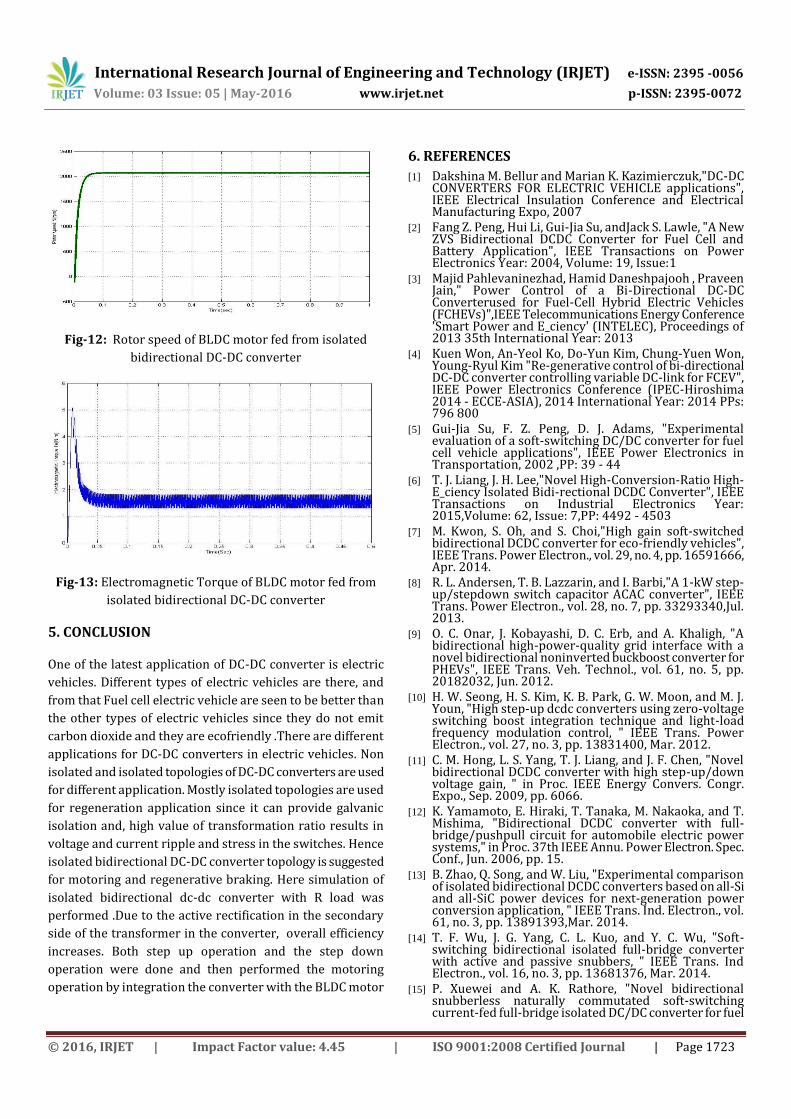
Fig-12: Rotor speed of BLDC motor fed from isolated
bidirectional DC-DC converter
Fig-13: Electromagnetic Torque of BLDC motor fed from
isolated bidirectional DC-DC converter
5. CONCLUSION
One of the latest application of DC-DC converter is electric
vehicles. Different types of electric vehicles are there, and
from that Fuel cell electric vehicle are seen to be better than
the other types of electric vehicles since they do not emit
carbon dioxide and they are ecofriendly .There are different
applications for DC-DC converters in electric vehicles. Non
isolated and isolated topologies of DC-DC converters are used
for different application. Mostly isolated topologies are used
for regeneration application since it can provide galvanic
isolation and, high value of transformation ratio results in
voltage and current ripple and stress in the switches. Hence
isolated bidirectional DC-DC converter topology is suggested
for motoring and regenerative braking. Here simulation of
isolated bidirectional dc-dc converter with R load was
performed .Due to the active rectification in the secondary
side of the transformer in the converter, overall efficiency
increases. Both step up operation and the step down
operation were done and then performed the motoring
operation by integration the converter with the BLDC motor
6. REFERENCES
[1] Dakshina M. Bellur and Marian K. Kazimierczuk,"DC-DC CONVERTERS FOR ELECTRIC VEHICLE applications", IEEE Electrical Insulation Conference and Electrical Manufacturing Expo, 2007
[2] Fang Z. Peng, Hui Li, Gui-Jia Su, andJack S. Lawle, "A New ZVS Bidirectional DCDC Converter for Fuel Cell and Battery Application", IEEE Transactions on Power Electronics Year: 2004, Volume: 19, Issue:1
[3] Majid Pahlevaninezhad, Hamid Daneshpajooh , Praveen Jain," Power Control of a Bi-Directional DC-DC Converterused for Fuel-Cell Hybrid Electric Vehicles (FCHEVs)",IEEE Telecommunications Energy Conference 'Smart Power and E_ciency' (INTELEC), Proceedings of 2013 35th International Year: 2013
[4] Kuen Won, An-Yeol Ko, Do-Yun Kim, Chung-Yuen Won, Young-Ryul Kim "Re-generative control of bi-directional DC-DC converter controlling variable DC-link for FCEV", IEEE Power Electronics Conference (IPEC-Hiroshima 2014 - ECCE-ASIA), 2014 International Year: 2014 PPs: 796 800
[5] Gui-Jia Su, F. Z. Peng, D. J. Adams, "Experimental evaluation of a soft-switching DC/DC converter for fuel cell vehicle applications", IEEE Power Electronics in Transportation, 2002 ,PP: 39 - 44
[6] T. J. Liang, J. H. Lee,"Novel High-Conversion-Ratio High-E_ciency Isolated Bidi-rectional DCDC Converter", IEEE Transactions on Industrial Electronics Year: 2015,Volume: 62, Issue: 7,PP: 4492 - 4503
[7] M. Kwon, S. Oh, and S. Choi,"High gain soft-switched bidirectional DCDC converter for eco-friendly vehicles", IEEE Trans. Power Electron., vol. 29, no. 4, pp. 16591666, Apr. 2014.
[8] R. L. Andersen, T. B. Lazzarin, and I. Barbi,"A 1-kW step-up/stepdown switch capacitor ACAC converter", IEEE Trans. Power Electron., vol. 28, no. 7, pp. 33293340,Jul. 2013.
[9] O. C. Onar, J. Kobayashi, D. C. Erb, and A. Khaligh, "A bidirectional high-power-quality grid interface with a novel bidirectional noninverted buckboost converter for PHEVs", IEEE Trans. Veh. Technol., vol. 61, no. 5, pp. 20182032, Jun. 2012.
[10] H. W. Seong, H. S. Kim, K. B. Park, G. W. Moon, and M. J. Youn, "High step-up dcdc converters using zero-voltage switching boost integration technique and light-load frequency modulation control, " IEEE Trans. Power Electron., vol. 27, no. 3, pp. 13831400, Mar. 2012.
[11] C. M. Hong, L. S. Yang, T. J. Liang, and J. F. Chen, "Novel bidirectional DCDC converter with high step-up/down voltage gain, " in Proc. IEEE Energy Convers. Congr. Expo., Sep. 2009, pp. 6066.
[12] K. Yamamoto, E. Hiraki, T. Tanaka, M. Nakaoka, and T. Mishima, "Bidirectional DCDC converter with full-bridge/pushpull circuit for automobile electric power systems," in Proc. 37th IEEE Annu. Power Electron. Spec. Conf., Jun. 2006, pp. 15.
[13] B. Zhao, Q. Song, and W. Liu, "Experimental comparison of isolated bidirectional DCDC converters based on all-Si and all-SiC power devices for next-generation power conversion application, " IEEE Trans. Ind. Electron., vol. 61, no. 3, pp. 13891393,Mar. 2014.
[14] T. F. Wu, J. G. Yang, C. L. Kuo, and Y. C. Wu, "Soft-switching bidirectional isolated full-bridge converter with active and passive snubbers, " IEEE Trans. Ind Electron., vol. 16, no. 3, pp. 13681376, Mar. 2014.
[15] P. Xuewei and A. K. Rathore, "Novel bidirectional snubberless naturally commutated soft-switching current-fed full-bridge isolated DC/DC converter for fuel
International Research Journal of Engineering and Technology (IRJET) e-ISSN: 2395 -0056
[16] SudhaMalapur, Shruthi.M.B, Nagaraja Bodravara Davanagere,"Comparison of Isolated and Non-Isolated Bidirectional DC-DC Converter Fed PMDC Motor", International Journal for Research in Applied Science and Engineering Technology (IJRASET),Volume3 Issue IV, April 2015
BIOGRAPHIES
Ms. Greeshma.M.S.i, M.Tech Student, Dept of EEE.Adi Shankara Institute Of Engineering And Technology. Received B.Tech in Electrical And Electronics Engineering from SCMS School Of Engineering And Technology. Areas of interests are Power electronics and electric drives .
Mrs. Nayana J,Assistant Professor, Dept of EEE, Adi Shankara Institute Of Engineering And Technology. Received B.Tech in Electrical And Electronics Engineering from Govt Engineering College, affiliated to MG University. in 2009. Received M. Tech degree in Power Electronics And Power System from Adi Shankara Insitute Of Engineering And Technology, in 2014. Having 7 years of teaching experience. Interesting area are Power electronics, Drives and Electrical Machines


![HIGH-CONVERSION-RATIO BIDIRECTIONAL DC–DC ......bidirectional dc –dc converter with a high convention ratio is a key component of battery applications [5] Isolated bidirectional](https://static.documents.pub/doc/80x56/5f0a32787e708231d42a7b2d/high-conversion-ratio-bidirectional-dcadc-bidirectional-dc-adc-converter.jpg)


