11
Analysis of Tube Configuration in a Tube Bundle in Horizontal, Two- Pass Condensers Engineering Project Master of Engineering in Mechanical Engineering Jennifer Tansey 12/15/11
| Date post: | 19-Dec-2015 |
| Category: |
Documents |
| View: | 222 times |
| Download: | 2 times |
Final Project Presentation:Analysis of Tube Configuration in a Tube
Bundle in Horizontal, Two-Pass Condensers
Engineering ProjectMaster of Engineering in Mechanical Engineering
Jennifer Tansey12/15/11
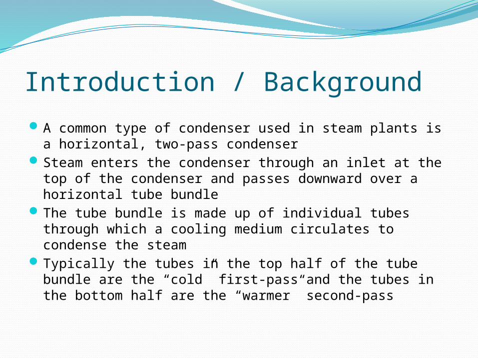
Introduction / BackgroundA common type of condenser used in steam plants is a
horizontal, two-pass condenserSteam enters the condenser through an inlet at the top of
the condenser and passes downward over a horizontal tube bundle
The tube bundle is made up of individual tubes through which a cooling medium circulates to condense the steam
Typically the tubes in the top half of the tube bundle are the “cold” first-pass and the tubes in the bottom half are the “warmer” second-pass
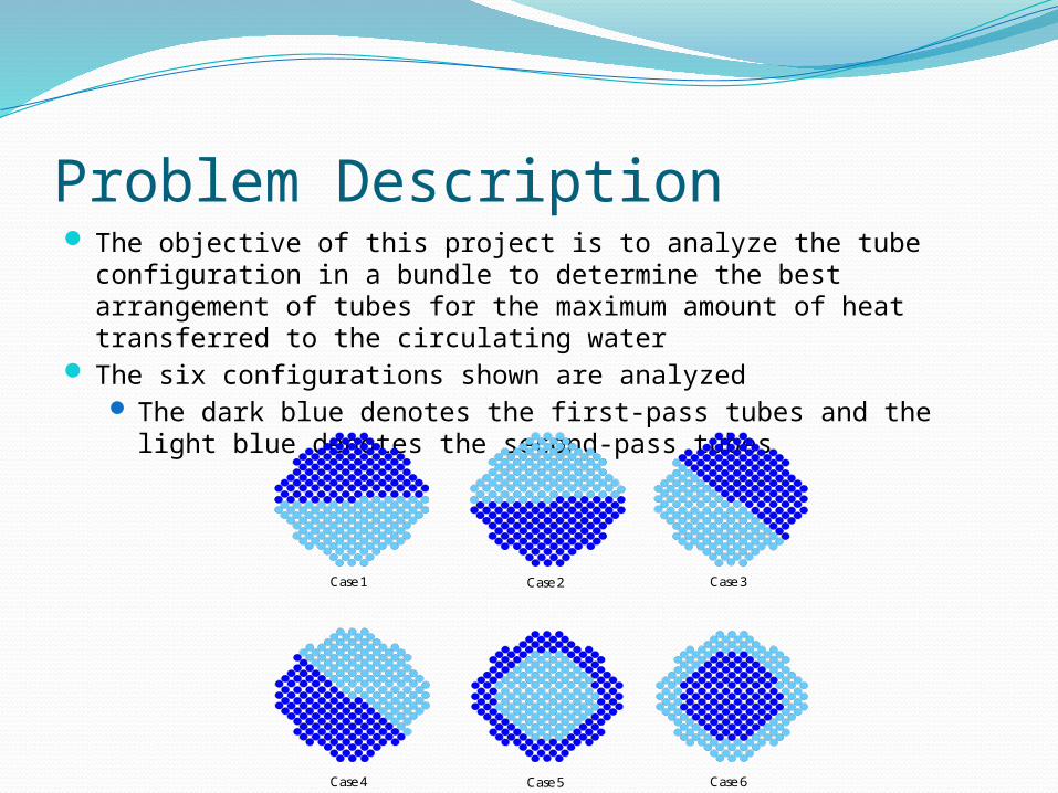
Problem Description The objective of this project is to analyze the tube configuration in
a bundle to determine the best arrangement of tubes for the maximum amount of heat transferred to the circulating water
The six configurations shown are analyzed The dark blue denotes the first-pass tubes and the light blue
denotes the second-pass tubes
11 11
11
11
11 11
Case 1 Case 2 Case 3
Case 4 Case 5 Case 6
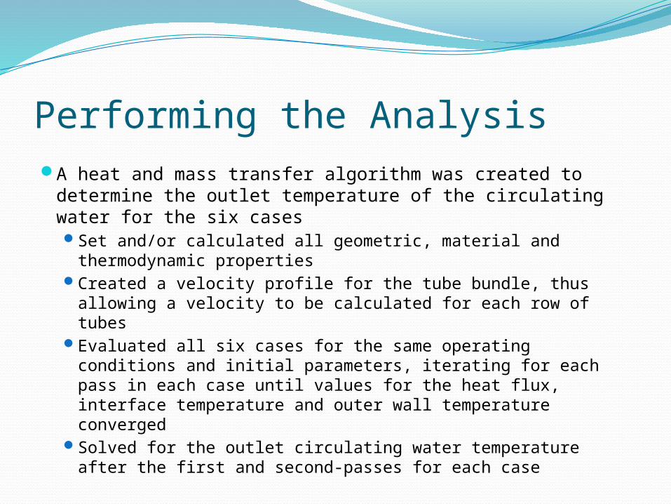
Performing the AnalysisA heat and mass transfer algorithm was created to
determine the outlet temperature of the circulating water for the six casesSet and/or calculated all geometric, material and
thermodynamic propertiesCreated a velocity profile for the tube bundle, thus
allowing a velocity to be calculated for each row of tubesEvaluated all six cases for the same operating conditions
and initial parameters, iterating for each pass in each case until values for the heat flux, interface temperature and outer wall temperature converged
Solved for the outlet circulating water temperature after the first and second-passes for each case
Post-ProcessingCompiled the converged results for the heat flux, interface
temperature and outer wall temperature for all six casesCalculated and plotted the temperature distribution over
the length of the tube bundle for both the first and second-passes using an averaged circulating water temperatures
Compared the circulating water temperatures for:All first-pass tubes
Average outlet temperature Average temperature along the tubes
All second-pass tubes Average outlet temperature Average temperature along the tubes

Post-ProcessingPerformed an energy balance to ensure that
the iterative algorithm produced accurate resultsTook into account the change in energy in the
system due to: Net loss in energy in the mixture Net gain in energy in the circulating water Net gain in energy in the condensate formed Net gain in energy in the tube walls
Showed less than 3% error, which can be attributed to the assumptions and simplifications made in the analysis
FLOW3D ModelingCreated input files for all six cases in FLOW3D to
simulate the velocity contours and steam temperature contours
Used the velocity profile from FLOW3D in Excel to repeat the algorithm with the new velocity profile
Analyzed and compared the results from the velocity profile created in the algorithm and the velocity profile obtained from FLOW3D
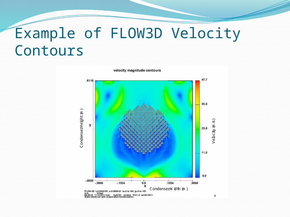
Example of FLOW3D Velocity Contours
CondenserHeight(m)
Velocity(m/s)
Condenser Width (m)
CondenserHeight(m)
Velocity(m/s)
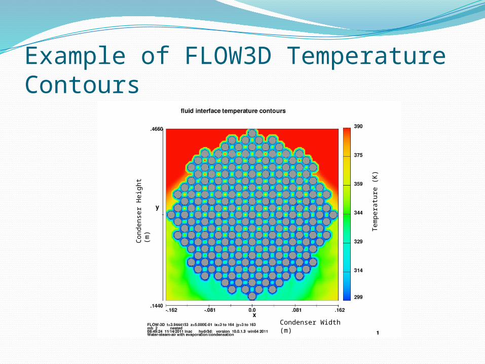
Example of FLOW3D Temperature Contours
Tem
pera
ture
(K
)
Cond
ense
r Hei
ght (
m)
Condenser Width (m)
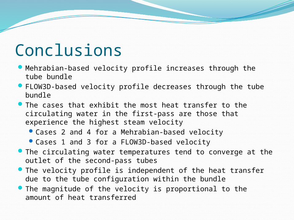
ConclusionsMehrabian-based velocity profile increases through the tube
bundleFLOW3D-based velocity profile decreases through the tube bundleThe cases that exhibit the most heat transfer to the circulating
water in the first-pass are those that experience the highest steam velocityCases 2 and 4 for a Mehrabian-based velocityCases 1 and 3 for a FLOW3D-based velocity
The circulating water temperatures tend to converge at the outlet of the second-pass tubes
The velocity profile is independent of the heat transfer due to the tube configuration within the bundle
The magnitude of the velocity is proportional to the amount of heat transferred
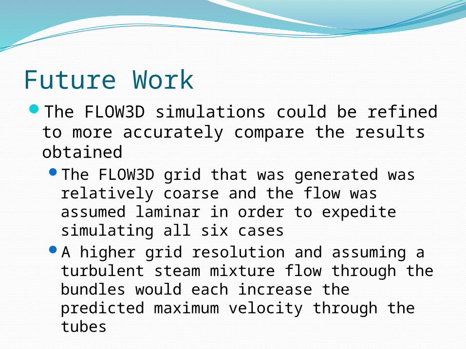
Future WorkThe FLOW3D simulations could be refined to
more accurately compare the results obtainedThe FLOW3D grid that was generated was
relatively coarse and the flow was assumed laminar in order to expedite simulating all six cases
A higher grid resolution and assuming a turbulent steam mixture flow through the bundles would each increase the predicted maximum velocity through the tubes


