FHWA Report No. FHWA-RD-99-146 Materials and Procedures for Repair of Joint Seals in Portland Cement Concrete Pavements Manual of Practice Federal Highway Administration U.S. Department of Transportation Strategic Highway Research Program National Research Council
Transcript
FHWA Report No. FHWA-RD-99-146
Materials and Procedures forRepair of Joint Seals in
Portland Cement Concrete Pavements
Manual of Practice
Federal Highway AdministrationU.S. Department of Transportation
Strategic Highway Research ProgramNational Research Council
FOREWORD
This manual (FHWA-RD-99-146) is an update of the StrategicHighway Research Program (SHRP) manual of practice(SHRP-H-349) on concrete pavement repair. The FederalHighway Administration, Long Term Pavement PerformanceProgram (LTPP) conducted five years of additional research onconcrete pavement repair after the conclusion of SHRP. Thisresearch validated the repair procedures contained in theoriginal SHRP manual. The manual presents updatedguidelines and recommendations to assist highway maintenanceagencies and other related organizations in planning,constructing, and monitoring the performance of concretepavement joint resealing projects. Included in the manual arediscussions pertaining to when joint resealing is appropriate, thetypes of sealant materials and construction methods that shouldbe used, how each individual step in a joint resealing operationshould be performed, and how the performance and cost-effectiveness of joint seals can be evaluated. This report will beof interest and benefit to various levels of agency maintenancepersonnel, from crew supervisors to the chief maintenanceengineer.
NOTICE
This document is disseminated under the sponsorship of theDepartment of Transportation in the interest of informationexchange. The United States Government assumes no liabilityfor its contents or use thereof. This report does not constitute astandard, specification, or regulation.
The United States Government does not endorse products ormanufacturers. Trade and manufacturers’ names appear in thisreport only because they are considered essential to the objectof the document.
9. Performing Organization Name and Address 10. Work Unit No. (TRAIS)
ERES Consultants A Division of Applied Research Associates, Inc. 11. Contract or Grant No.
505 W. University Avenue DTFH61-93-C-00051 Champaign, IL 61820-3915 13. Type of Report and Period Covered
12. Sponsoring Agency Name and Address Updated Manual of Practice Federal Highway Administration October 1993 - June 1999 Pavement Performance Division 6300 Georgetown Pike 14. Sponsoring Agency Code
19. Security Classif. (of this report) 20. Security Classif. (of this page) 21. No of Pages 22. Price
Unclassified Unclassified 127
Form DOT F 1700.7 (8-72) Reproduction of completed page authorized
No restrictions. This document is available to the public through the National Technical Information Service, Springfield, Virginia 22161.
L.D. Evans, K.L. Smith, and A.R. Romine
The Strategic Highway Research Program (SHRP) H-106 maintenance experiment and the Federal Highway Administration(FHWA) Long-Term Monitoring (LTM) of Pavement Maintenance Materials Test Sites project studied the resealing of jointsin concrete pavements. Many different sealant materials and resealing methods were investigated between 1991 and 1998through test sites installed at five locations in the United States. The findings of these combined studies have been merged withstandard highway agency procedures to provide the most useful and up-to-date information on the practice of concrete jointresealing.
This Manual of Practice is an updated version of the 1993 SHRP Joint Seal Repair Manual. It contains the latest informationpertaining to the performance of sealants and resealing methods, the availability and relative costs of sealant materials, and theproper ways of planning, designing, constructing, and monitoring the performance of joint resealing projects. It also providesan updated partial listing of material and equipment manufacturers.
This Manual is intended for field and office personnel within highway maintenance agencies and contracted maintenance firms.It contains valuable information for supervisors and foremen in charge of individual resealing operations, engineers in charge ofplanning and overseeing many joint resealing projects, and managers in charge of establishing resealing policies and standards.
Materials and Procedures for Repair of Joint Seals in Portland Cement Concrete Pavements---Manual of Practice
iii
Preface
This manual is intended for use by highway maintenanceagencies and contracted maintenance firms in the field and inthe office. It is a compendium of good practices for portlandcement concrete (PCC) joint resealing operations, stemmingfrom the Strategic Highway Research Program (SHRP)pavement maintenance studies and a follow-up study sponsoredby the Federal Highway Administration (FHWA).
In SHRP project H-105, Innovative Materials and Equipmentfor Pavement Surface Repair, the researchers conducted amassive literature review and a nationwide survey of highwayagencies to identify potentially cost-effective pavement repairand treatment options (Smith et al., 1991). The informationand findings from that study were then used in the subsequentfield experiments conducted under SHRP project H-106,Innovative Materials Development and Testing.
In project H-106, many different test sections were installed andevaluated to determine the cost-effectiveness of maintenancematerials and procedures. Test sections were installed at 22sites throughout the United States and Canada between March1991 and February 1992, under the supervision of SHRPrepresentatives. The researchers collected installation andproductivity information at each site and periodically evaluatedthe experimental repairs and treatments through the end of1992. The first version of this manual was prepared in October1993 and was based on this work effort.
Following the conclusion of SHRP H-106 in 1993, the FHWAsponsored a study to continue monitoring the performance ofthe experimental repairs and treatments, beginning in October1993. Under the Long-Term Monitoring (LTM) of PavementMaintenance Materials Test Sites project, the repairs andtreatments were evaluated annually through the end of 1997.
iv
Pertinent long-term performance and cost-effectivenessinformation generated by the continued monitoring of theexperimental joint resealing treatments has been included in thisrevised manual.
For the reader's convenience, potentially unfamiliar terms areitalicized at their first occurrence in the manual and are definedin a glossary. Readers who want more information on topicsincluded in this manual should refer to the reference listprovided at the back. The final report for the H-106/LTMportland cement concrete (PCC) joint resealing study may be ofparticular interest to many readers (Evans et al., 1999). Itdetails the installation procedures, laboratory testing of thematerials, and field performance of each joint resealingtreatment type investigated.
v
Acknowledgments
The research described herein was supported by the StrategicHighway Research Program and the Federal HighwayAdministration. SHRP was a unit of the National ResearchCouncil that was authorized by section 128 of the SurfaceTransportation and Uniform Relocation Assistance Act of1987.
Special thanks are due the project management teams at SHRPand the FHWA, and to the following State highway agencies:
! Arizona Department of Transportation! Colorado Department of Highways! Iowa Department of Transportation! Kentucky Transportation Cabinet! South Carolina Department of Highways and Public
Transportation
The contributions of the following individuals are alsoacknowledged: Michael Darter, Sam Carpenter, DavidPeshkin, Mike Belangie, Henry Bankie, Charlie Smythe, andJim Chehovits.
This manual has been prepared for use by maintenanceengineers, maintenance field supervisors, crew persons,maintenance contractors, and inspectors as an easy referencefor resealing* transverse and longitudinal joints in portlandcement concrete (PCC) pavements.
1.1 Scope of Manual
Included in this manual are descriptions of procedures andmaterials recommended for resealing joints in PCC pavements. Guidelines for planning a resealing project and steps forinstalling joint seals and inspecting the process are presented. The resealing of concrete-asphalt shoulder joints and sealingcracks in PCC pavements are not addressed.
The information contained in this manual is based on the mostrecent research, obtained through reviews of literature and ofcurrent practice, as well as from the field results of a 7-yearstudy (Smith et al., 1991; Evans et al., 1999). This studyinvestigated the performance in PCC joints of various hot- andcold-applied sealants using several methods of installation.
* Italicized words are defined in the glossary.
2
1.2 Overview
Several steps are required for successful resealing of joints inPCC pavements. The first is determining the need for resealing. Chapter 2 of this manual contains a general procedure that canbe easily modified to meet the needs of any highway agency.
Once the need for resealing is determined, the next step isplanning the operation. Chapter 3 leads the maintenanceplanner through the steps for selecting sealant and accessorymaterials, choosing preparation and installation procedures,specifying equipment, and estimating material and laborrequirements.
The construction phase of joint resealing is described in chapter4. Details of each step of the preparation and installationoperations are listed, along with troubleshooting procedures foreach operation.
The appendixes provide material testing specifications, samplecost-effectiveness calculations, safety precautions, andinspection checklists to help ensure good resealing practicesand high-quality results.
3
2.0 Need for Joint Resealing
Excessive delay in replacing a failing sealant system in concretepavement joints can result in more rapid deterioration of thepavement. However, if sealant is replaced too early, preciousmaintenance funds may not have been used in the most cost-effective manner. How, then, can those responsible formaintenance determine when is the best time to reseal joints inconcrete pavements? Some States specify that joints beresealed when a specified amount of sealant material (25 to 50percent) has failed, allowing moisture or incompressiblematerials to progress past the sealant to the underlying layers. Other agencies base their decision on pavement type, pavementand sealant condition, and available funding.
A more complete method for determining whether a pavementneeds to be resealed is to calculate rating numbers based on thesealant and pavement condition, traffic levels, and climaticconditions. Figure 1 presents a worksheet that can be used toestimate these properties, and table 1 gives recommendationsabout the need to reseal based on these properties. Thefollowing sections assist in determining the necessary ratingsand conditions.
2.1 Seal Condition
Joint sealant system effectiveness is judged by the sealant'sability to resist embedment of incompressible materials and thesealant system's success in preventing entry of water andincompressible materials into the joint. To evaluate pavementseal condition, the following steps should be completed andresults recorded on the pavement survey form:
Avg annual precip., mm Pavement Rating Good Fair Poor
Days < 0oC
Current Joint Design Avg low / high temp, oC
Climatic Region a WF WNF DF DNF
Sealant age, yrs
Traffic ConditionsAvg. sealant depth, mm
Avg. joint width, mm
ADT (vpd); % Trucks Avg. joint depth, mm
Traffic Level b Low Med High Max. joint spacing, m
a See table 2.b See table 3.
5
Table 1. Decision table for resealing PCC joints.
SealantRatinga
Pvmt.Rating
TrafficRating
Climatic Region
Freeze Nonfreeze
Wet Dry Wet Dry
Fair Good Low Possibly Possibly Possibly Possibly
Fair Good Med Yes Possibly Possibly Possibly
Fair Good High Yes Yes Yes Possibly
Fair Fair Low Yes Possibly Possibly Possibly
Fair Fair Med Yes Yes Yes Possibly
Fair Fair High Yes Yes Yes Possibly
Fair Poor Low Possibly Possibly Possibly Possibly
Fair Poor Med Yes Yes Yes Possibly
Fair Poor High Yes Yes Yes Yes
Poor Good Low Yes Possibly Possibly Possibly
Poor Good Med Yes Yes Yes Possibly
Poor Good High Yes Yes Yes Yes
Poor Fair Low Yes Yes Yes Possibly
Poor Fair Med Yes Yes Yes Yes
Poor Fair High Yes Yes Yes Yes
Poor Poor Low Yes Yes Yes Possibly
Poor Poor Med Yes Yes Yes Yes
Poor Poor High Yes Yes Yes Yes
a Sealants rated in "Good" condition do not require replacement.
6
% L 'Lf
Ltot
x 100 Eq. 1
1. Choose 10 or more joints whose sealant condition isrepresentative of the entire site. If large variations incondition are evident, subdivide the site into sectionshaving similar seal condition and evaluate 5 to 10 jointsfrom each section.
2. Cut 50-mm samples of sealant from a few joints andmeasure the joint width, depth, and sealant thickness.
3. Determine from the construction records the type andage of the sealant, the design joint width, and sealantthickness.
4. Record the maximum spacing between joints.
Carefully inspect each of the chosen joints, recording thefollowing items on the pavement survey form:
! Water Resistance— The percentage of overall jointlength where water can bypass the sealant and enter thejoint.
! Stone Intrusion— The amount of stones, sand, anddebris embedded in the sealant.
Common joint seal distresses include loss of bonding to theconcrete sidewall (figure 2), cohesive failure (figure 3), spalls,and torn or missing sealant. They reduce water resistance andallow moisture, sand, and dirt to enter the joint. Bond failurecan be determined by pulling the sealant away from the jointedge and inspecting for adhesion failure. Full-depth spalls canbe identified by gently inserting a dull knife into the spall andobserving if the knife tip can pass below the sealant. Anothermethod for locating areas of bond failure is with the Iowavacuum (IA-VAC) tester, developed by the Iowa Departmentof Transportation (DOT). The percentage of water resistanceloss can be computed using equation 1.
7
Figure 2. Sealant adhesion failure.
Figure 3. Full-depth cohesion failure.
8
SCN ' 1(L) % 2(M) % 3(H) Eq. 2
where: %L = Percent length allowing water to enter joint.Lf = Total length of joint sections allowing the
entrance of water, m.Ltot = Total joint section length evaluated, m.
Stone intrusion can be rated using the following criteria, and therating should be recorded on the pavement survey form:
Low = Occasional stones or sand stuck to the top ofthe sealant (or material embedded on thesurface of the sealant/channel interface).
Medium = Sand or debris stuck to sealant and somedebris deeply embedded in the sealant.
High = Much sand and debris stuck to and deeplyembedded in the sealant or filling the joint.
Next, determine the sealant rating by calculating the sealcondition number (SCN). This number can be computed usingthe following equation:
where:SCN = Seal condition number.L = The number of low-severity seal conditions
recorded on the pavement survey form.M = The number of medium-severity seal
conditions.H = The number of high-severity seal conditions.
Use the SCN and the following rating to determine whether theexisting joint seal is in good, fair, or poor condition, and circlethe correct seal rating on the pavement survey form.
9
Seal Rating SCN
Good 0 - 1
Fair 2 - 3
Poor 4 - 6
Results of a seal condition rating can also be used to monitorthe performance of joint seals and to assist in follow-uprehabilitation planning.
2.2 Pavement Condition
Pavement condition is the next item to identify. A pavementwill provide several indicators that the joint seal is notperforming adequately and is allowing too much water to reachthe underlying layers. These indicators include the following:
! Surface staining or the accumulation of fine material onthe surface close to joints or cracks indicates pumpingof the base or subbase. This results, in part, from excessmoisture, and it contributes to formation of voidsbeneath the pavement, cracks, and corner breaks.
! Faulting, or drop-off between adjacent slabs, canindicate that excess moisture is reaching a water-susceptible base or subgrade, and that voids are formingbeneath one side of the pavement as a result of continualtraffic.
! D-cracking can result from excess moisture beneath apavement.
A pavement system can also manifest the effects of the entranceof stones and other incompressible materials into pavementjoints by the following:
10
PCN ' 1(L) % 2(M) % 3(H) Eq. 3
! Compression-related spalling of the walls of joints thatare filled with sand and stones.
! Blowups and shattering of slab edges, as well aspermanent increases in joint width causing closure ofnearby expansion joints.
To evaluate the condition of a pavement considered forresealing, record the following items in the pavement conditionsection of the concrete pavement/joint survey form (figure 1). These items should be based on field inspection and themaintenance schedule.
! The estimated number of years before the pavementrequires major rehabilitation.
! The average vertical faulting movement.! The percentage of slabs containing corner breaks.! The percentage of joints visibly indicating pumping.! The percentage of slabs containing full-depth spalls
extending greater than 25 mm from the face of the joint.
To determine a pavement condition number (PCN), use figure 1and equation 3.
where:PCN = Pavement condition number.L = The number of low-severity pavement
condition indicators from the pavementsurvey form.
M = The number of medium-severity pavementcondition indicators.
H = The number of high-severity pavementcondition indicators.
11
Use the PCN and the following ratings to determine thecondition of the existing pavement and circle the correctpavement rating on the pavement survey form:
Pavement Rating PCN
Good 0 - 3
Fair 4 - 5
Poor 6 - 15
2.3 Environmental Conditions
The effects of extreme temperatures and precipitation on jointseal and pavement performance cannot be minimized. Inextremely cold temperatures, sealants are stretched the most aspavements shrink and joints widen. Extremely hot temperaturescan compress improperly placed sealant, forcing it above thepavement surface where it may be pulled out by vehicle tires.
Wet climatic regions need highly effective seals (approaching100 percent effectiveness) to prevent water damage tosusceptible base and pavement structures. Dry climates alsomay require highly effective seals to prevent the intrusion ofincompressible material into the joint, which can result in jointgrowth, blowups, and structural damage.
When evaluating the climatic conditions that a pavement willexperience, determine the following information and enter it inthe environmental condition section of the concretepavement/joint survey form:
12
Table 2. Climatic region parameters
Climatic Region
Mean annual days < 0oC
Average annualprecipitation
Wet-Freeze > 100 > 635 mm
Wet-Nonfreeze < 100 > 635 mm
Dry-Freeze > 100 < 635 mm
Dry-Nonfreeze < 100 < 635 mm
! The normal annual total precipitation for the location.! The mean number of days in a year with a minimum
temperature of 0oC or below. ! The highest and lowest recorded temperatures.
This information is available from the National Climatic DataCenter in Asheville, North Carolina, or from local weatherrecording stations. Then, using the information from figure 1and table 2, identify the climatic region in which the pavementis located. Circle the correct climatic region on the pavementsurvey form.
2.4 Traffic Conditions
To identify traffic conditions, obtain the average daily traffic(ADT) level and the percent truck traffic. Determine the trafficlevel rating from table 3. If the percent trucks is greater than10 percent or the expected growth rate is greater than 5percent, use the next higher traffic level rating.
13
Table 3. Traffic-level rating.
Traffic Level ADT, vpd all lanes
Low < 5,000
Medium 5,000 to 35,000
High >35,000
2.5 Determining the Need to Reseal
After completing the pavement evaluation worksheet, use table1 and the calculated SCN, PCN, the traffic rating, and theclimatic region to evaluate the need for resealing. The basis forthis table is engineering experience; however, it can be adjustedto the needs and policies of individual State agencies. Choosethe row with the combination of sealant, pavement, and trafficrating from the three left-hand columns that match thepavement being evaluated. Then find the intersection of thatrow with the appropriate climatic region to obtain therecommendation on the need for resealing.
If the recommendation is that sealing is "possibly" needed, thenthe case is borderline, and good judgment should be used indetermining the need to reseal. If D-cracking is evident in thepavement surface, it may be more critical to completely seal thetransverse and longitudinal pavement joints. When an overlayor rehabilitation is scheduled within 3 to 5 years, sealing couldbe delayed unless pavement or base damage would result.Agencies should use local experience for final determination ofwhether and how to reseal.
15
3.0 Planning and Design
3.1 Primary Considerations
After determining the need to reseal the joints in a concretepavement section, it is important to plan the sealing operationto ensure that a proper resealing job is completed. Properplanning should take into account the following factors:
! The long- and short-term objectives for resealing.! The current sealant and pavement condition and the
place of the resealing effort in an overall maintenanceplan.
! The applicability and documented performance of thesealant materials chosen.
! The effectiveness of the equipment and installationmethods chosen.
! The level of strain placed on the sealant system as aresult of the dimensions of the joint reservoir.
! The minimization of traffic disruption, increased workersafety, and efficient installation rates.
3.2 Objective of Resealing
When beginning, it is important to determine the objective ofthe resealing project. Possible objectives include the following:
! Temporarily seal the pavement joints for 1 to 2 yearsuntil the pavement is overlaid or replaced.
! Seal and maintain watertight joints for 3 to 5 years.! Seal and maintain watertight joints for a period
extending more than 5 years.
16
Table 4. Relationship between pavement conditionand sealing objectives.
Condition Objective
Pavement to be overlaid in 1 to 2 years.
Temporarily seal pavement.
Pavement in fair condition. Majorrehabilitation scheduled in 5 years.
Maintain seal until rehabilitation.
Pavement in good condition andcarries high level of traffic.
Maintain seal as long as possible.
Each of these objectives may be correct for a different situation,depending primarily on the pavement condition and the trafficlevel, as illustrated in table 4.
In dry climates, it is more important to keep sand and dirt outof the joints to prevent spalling and blowups. A sealant shouldthen be chosen that does not allow sand to penetrate the sealantsurface. In hot climates, some sealants flow down into thejoint, or track on the surface, or allow stones to becomeembedded in the sealant. In some situations, a jet-fuel resistant(JFR) sealant material is required. In some pavements, onlycertain areas of sealant have failed and selective replacement isneeded. Consequently, when choosing sealant materials andinstallation methods, the objectives must match therequirements of the situation.
3.3 Accounting for Existing Conditions
The condition of a pavement when it is resealed can greatlyaffect the performance of the seal. Corner breaks, large spalls,voids beneath the pavement, faulting, and poor load transfercan all reduce the effective life of resealed joints. Depending onexisting conditions, some of these pavement distresses shouldbe repaired before sealant is installed (Collins et al., 1986).
17
Specifically, prior to resealing, the following repairs should beconsidered (Darter et al., 1985):
! Full-depth repair of corner breaks and deep spalls.! Partial-depth repair of spalls that extend more than 25
mm from the face of the joint.! Improving subdrainage or roadside drainage. ! Restoring load transfer at joints and cracks where
poor load transfer exists.! Undersealing the pavement where voids exist. ! Grinding the pavement surface to restore a smooth
ride or to improve traction.
Each of these repairs, if needed, should be completed beforeresealing begins. The condition of the sealant in longitudinaljoints and transverse cracks should also be evaluated todetermine if resealing is appropriate (Carpenter et al., 1987). Studies have shown that extensive pavement damage can occurdue to the large amount of water entering a pavement systemthrough open transverse cracks and longitudinal joints.
The condition of the existing joints and sealant can reveal muchabout the conditions under which it failed. Several of theseindicators are listed in table 5. When these or other conditionsare evident, care should be taken to address and eliminate themfor the resealing project.
3.4 Selecting a Sealant Material Type
Sealant materials are subjected to very harsh conditions. Selected sealants must have the following capabilities:
Sealant pulled away from edgesalong majority of the site.
Large amount of joint movement. Poor sealant or placementmethods.
Sealant pulled away from jointedges at random positions.
Joint may not have been cleanedproperly.
Sealant tracked on pavement. Sealant overheated,contaminated, or has too low asoftening point.
! Withstand horizontal movement and vertical shear atall temperatures to which they are exposed.
! Withstand environmental effects such as weathering,extreme temperatures, and excess moisture.
! Resist penetration by stones and sand at alltemperatures.
! Maintain complete bond to concrete joint sidewalls atall temperatures.
There are a wide variety of sealant materials on the market,each with its own characteristics and costs. However, no onesealant can meet the demands of every resealing project. Sealant selection should be based on the objectives of theresealing project.
Table 6 contains a listing of sealant material types commonlyused in resealing joints in PCC pavements. Applicablespecifications are also listed. To help the designer in choosing asealant material, the allowable extension and cost range areincluded. The allowable extension is the manufacturer-recommended maximum in-place sealant extension.
19
Table 6. Summary of sealant materials.
Sealant Material Applicable SpecificationsDesign
Extension, % a Cost Range,
$/L b
PVC Coal Tar ASTM D 3406 10 to 20% $1.75 to $2.75
RubberizedAsphalt
ASTM D 1190,AASHTO M 173,ASTM D 3405,
AASHTO M 301
15 to 30% $0.60 to$1.00
Low ModulusRubberized
Asphalt
ModifiedASTM D 3405 30 to 50% $0.70 to
$1.20
Polysulfide(1 & 2 Part) Fed SS-S-200E 10 to 20% Not
Available
Polyurethane Fed SS-S-200E 10 to 20% $5.20 to$7.20
Silicone(non-sag) ASTM D 5893 30 to 50% $6.50 to
$9.00
Silicone(self-leveling) ASTM D 5893 30 to 50% $6.50 to
$9.50
a Consult manufacturers for specific design extensions.b Based on 1998 estimated costs.
Compression seals are not typically used when the pavementjoints are spalled, since the seals tend to twist or move up ordown in the joint at locations where the joint edge is notvertical and completely smooth.
Many agencies have full-scale testing programs to determinethe performance of potential materials under local conditions. Thorough field and laboratory testing is recommended beforeany sealant is used on a large-scale project. Commonly usedlab specifications are shown in appendix A.
20
A life-cycle cost analysis (LCCA) should be performed todetermine the material with the least average annual cost overthe expected life of the pavement. Section 3.11 includes aworksheet to assist in conducting an LCCA.
3.5 Selecting Backer Materials
Backer rod is typically inserted in PCC joints prior to resealingto keep the sealant from sinking into the reservoir. It alsokeeps the sealant from bonding to the bottom of the reservoirand, if properly selected and installed, it helps maintain theproper sealant thickness. The rod must be flexible,compressible, non-shrinking, non-reactive, and non-absorptive. Shrinking rod may allow sealant to flow past the rod before thesealant sets. Backer rod that reacts with certain sealants mayproduce bubbles in or staining of the sealant. Finally, backerrod that absorbs water may shorten the life of the sealantmaterial.
Several currently available types of backer rod are described intable 7. Each type has specific properties and intended uses. For example, several backer rod types are designed towithstand the extreme temperatures of hot-applied sealants,while others are intended only for cold-applied sealants.
Softer, extruded foam rods have been developed to better sealjoints with irregular edges. Backer tapes that require a moreshallow joint have also been used.
The manufacturers’ recommendations should be followed whenselecting rod type, since sealant and backer rod must becompatible. The more commonly used backer rod materials for
21
Table 7. Backer rod materials.
Backer Material Type
Applicable Standard Properties Compatibility
Extruded closed-cell polyethylene
ASTM D 5249Type 3
NMA,ECI, NS
Most cold-applied sealants
Cross-linkedextruded closed-cell polyethylene
ASTM D 5249Type 1
HR,NMA,
ECI, NS
Most hot- andcold-applied
sealants
Extrudedpolyolefin
ASTM D 5249Type 3
NMA, NS,NG, CI, IJ
Most cold-applied sealants
CI = Chemically inert NG = Non-gassingECI = Essentially chemically inert NMA = Non-moisture absorbingHR = Heat resistant NS = Non-stainingIJ = Fills irregular joints well
hot-applied sealants are cross-linked extruded foam rods. Forcold-applied sealants, extruded closed-cell polyethylene foam orextruded polyolefin foam rod is typically used. The roddiameter should be at least 25 percent larger than the jointwidth. Backer rod is available in diameters ranging from 10 to75 mm or more. Since joint widths may vary within arehabilitation project, a sufficient range of rod sizes should beon hand to obtain a tight seal in all joints.
3.6 Selecting Primer Materials
In areas where high humidity and moisture make it difficult toobtain a good bond between the sealant and the concrete,primer may be recommended by the planner or the sealantmanufacturer. The purpose of a primer is to bond to theconcrete surface and provide a surface to which the new sealantcan bond well. Primer may also be used when past experience
22
indicates that it is difficult to obtain a good bond with thespecified sealant. Difficulties in obtaining a good bond withsoft aggregate can also be reduced by use of a primer.
Primers are currently used in only a small percentage of majorPCC resealing operations, with most of the use occurring in wetor cold climates. Consult sealant manufacturers for primer typerecommendations when the need for priming the joints exists.
3.7 Selecting Joint Reservoir Dimensions
The width of a joint and the thickness of the sealant in that jointcan significantly affect the performance of the seal (USAF,1983; ACI, 1990). If a joint is too narrow and temperaturechanges cause the joint to widen significantly, the sealant maybe stretched beyond its breaking point or pulled away from theconcrete. In addition, if a thick sealant is stretched, it may tearor not stick to the concrete, in the same way that a thick rubberband cannot be stretched as far as a thin one before tearing.
In designing the dimensions of a joint sealant and the sealantreservoir, two major items must be determined: the shape factorand the expected joint movement. Figure 4 shows thedimensions of a typical sealant reservoir containing sealantmaterial and backer rod. The shape factor is the ratio of thesealant width to the thickness (W:T). The sealant recess isdesignated as "R," and the joint channel depth is "D."
Manufacturers' recommendations should be followed whenchoosing a shape factor. Typical recommended shape factorsare shown in table 8. Silicone manufacturers recommend aminimum thickness of 6 mm and a maximum of 13 mm.
23
Sealant
Backer Rod
W
DTR
Figure 4. Typical joint cross section.
Table 8. Typical recommended shape factors.
Sealant Material Type
Typical Shape Factor (W:T)
Rubberized Asphalt 1:1
Silicone 2:1
PVC Coal Tar 1:2
Polysulfide and Polyurethane 1:1
24
M ' C L a T Eq. 4
%Emax ' 100Mmax
WinitEq. 5
Mmax ' 2 M Eq. 6
The maximum joint opening movement for rehabilitated jointseals can be estimated using equation 4 (Bodocsi et al., 1992).
where: M = Joint opening movement caused bytemperature change of PCC, mm.
C = Subbase/slab friction resistance adjustmentfactor (0.65 for stabilized subbase, 0.80 forgranular subbase).
a = Thermal coefficient of contraction for PCC(9.0 to 10.8 x 10⁻⁶/oC).
L = Joint spacing, mm.T = Temperature range (temperature at placement
minus lowest mean monthly temperature), oC.
Based on equation 4, the percent elongation that the newsealant must allow is determined by the following equation:
where: %Emax = Estimated elongation, percent.Mmax = Joint opening movement caused by
change of PCC temperature, mm.Winit = Joint width at the time of sealant
placement, mm.
Some engineers prefer to determine Mmax using the saferassumption that a joint between two slabs may be called uponto take the total movement of both slabs. In this assumption:
25
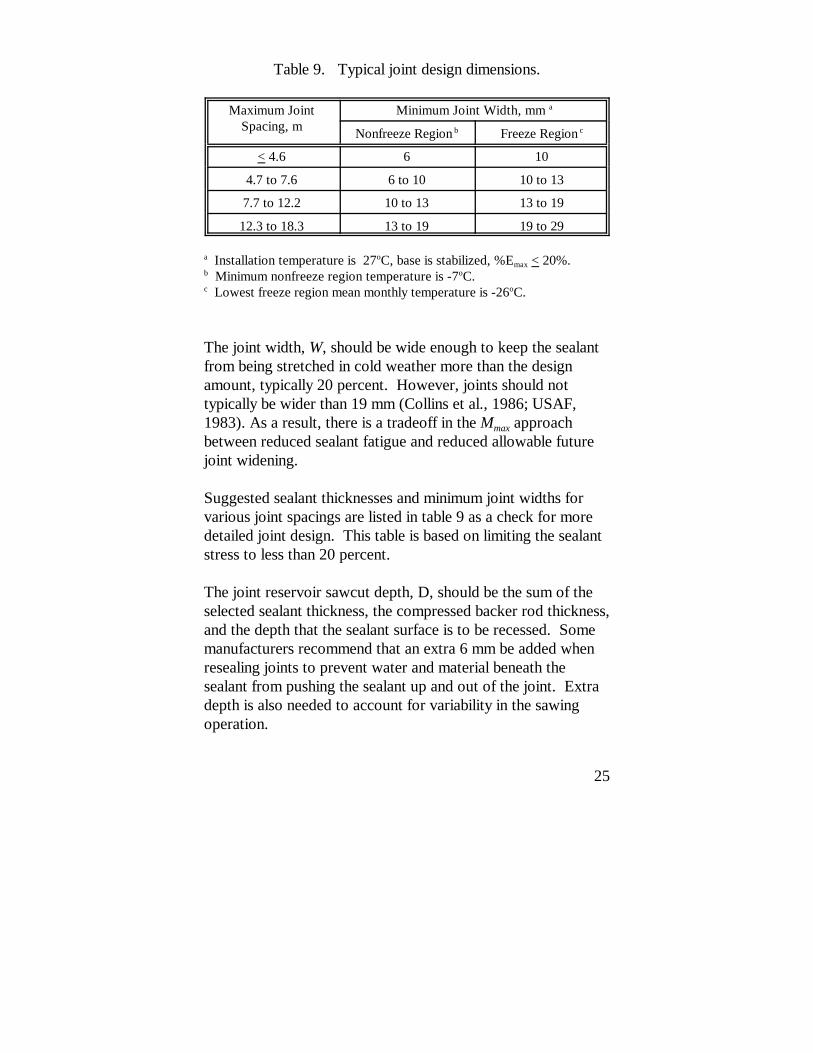
Table 9. Typical joint design dimensions.
Maximum JointSpacing, m
Minimum Joint Width, mm a
Nonfreeze Region b Freeze Region c
< 4.6 6 10
4.7 to 7.6 6 to 10 10 to 13
7.7 to 12.2 10 to 13 13 to 19
12.3 to 18.3 13 to 19 19 to 29
a Installation temperature is 27oC, base is stabilized, %Emax < 20%.b Minimum nonfreeze region temperature is -7oC.c Lowest freeze region mean monthly temperature is -26oC.
The joint width, W, should be wide enough to keep the sealantfrom being stretched in cold weather more than the designamount, typically 20 percent. However, joints should nottypically be wider than 19 mm (Collins et al., 1986; USAF,1983). As a result, there is a tradeoff in the Mmax approachbetween reduced sealant fatigue and reduced allowable futurejoint widening.
Suggested sealant thicknesses and minimum joint widths forvarious joint spacings are listed in table 9 as a check for moredetailed joint design. This table is based on limiting the sealantstress to less than 20 percent.
The joint reservoir sawcut depth, D, should be the sum of theselected sealant thickness, the compressed backer rod thickness,and the depth that the sealant surface is to be recessed. Somemanufacturers recommend that an extra 6 mm be added whenresealing joints to prevent water and material beneath thesealant from pushing the sealant up and out of the joint. Extradepth is also needed to account for variability in the sawingoperation.
26
3.8 Selecting Preparation and Installation Procedures
The type of joint cleaning procedures and the final cleanlinessof the concrete joint walls prior to sealant installation cansignificantly affect the performance of sealant materials. As arule, the cleaner and drier the joint surfaces are, the better asealant will adhere, and the more effective it will be. Therefore,preparation and installation procedures should be chosen ascarefully as sealant materials.
The selection of which combination of preparation andinstallation procedures to use should be based on the conditionand requirements of each individual resealing project. Fourcombinations are shown in table 10. Each option, if followedcompletely, should result in clean joint surfaces and increase thechances for good performance.
Option 1 should be considered when:
! The resealing project carries a high volume of traffic.! A high-quality sealant is being used.! Joint widths or depths do not meet the minimum design
requirements.! The existing sealant is hardened and will not melt and
"gum-up" the saw blades.
Option 2 differs from option 1 only by the elimination of waterwashing. This option can be used only when it can bedemonstrated that sufficient joint surface cleanliness can beachieved without water washing.
Option 3 adds a plowing operation to the option 2 procedures. It should be used when:
! A saw is melting the existing sealant and cannot removethe sealant efficiently by itself.
! The joint dimensions are not adequate.
Option 4 replaces the sawing operation with an effectiveplowing operation. It can significantly reduce the preparationtime and, since it is a dry operation, it allows immediatecleaning and resealing. It may only be used if:
! The joint dimensions are adequate.! The plowing equipment removes more than 95 percent
of the sealant from the joint faces, leaving fresh,unspalled concrete.
! The sandblaster is able to efficiently remove anyremaining sealant.
If compression seals are being replaced with formed-in-placesealant, sawing is not required when sandblasting cancompletely remove the old lubricant from the joint walls(Collins, 1986).
Several methods of sealant installation have also been used withvarying results (Smith et al., 1991; Evans et al., 1993; Lynch etal., 1993; Evans et al., 1999). These include:
28
! Recessing the sealant below the pavement surface.! Keeping the sealant surface level with the pavement
surface.! Overbanding sealant onto the pavement surface.
Overbanded seals tend to oxidize at a slower rate than recessedasphalt-based sealants because of the massaging action of traffictires. As a result, adhesion failures may occur more quickly inrecessed sealants. A 7-year study of joint seals in five Statesindicates that overbanded ASTM D 3405 seals have statisticallyoutperformed recessed seals even when installed in transversejoints on heavily trafficked roadways (Evans et al., 1999).
In longitudinal lane-shoulder joints, overbanding may providebetter performance than recessed seals. Therefore, in reducedtraffic areas, such as low-volume roads or lane-shoulder joints,overbanded sealants may be the most effective choice.
There are two drawbacks of overbanding on PCC pavements. First, overbanded sealant material is typically worn away bytraffic within 1 to 3 years. After it is worn, traffic tires tend topull the sealant from the joint edge, leading to adhesion failure. Second, the scraping action of ice blades on highways in coldregions tends to pull up overbanded seals from the pavementsurface.
Silicone sealants should never be overbanded or flush with thepavement surface. Manufacturers recommend a minimum of 7to 10 mm recess below the pavement surface for all siliconesealants to avoid the premature adhesion failure noted in theLong-Term Pavement Performance (LTPP) Specific PavementStudies (SPS)-4 test sections in four States (Smith et al., 1999).
29
3.9 Selecting Equipment
Selection of equipment for the resealing process should bebased on its ability to complete the task. This ability should beproven prior to beginning the resealing operation byconstructing a test resealing section.
A contractor or highway maintenance crew should be allowedto choose the equipment that will effectively clean and resealconcrete joints in the most efficient manner. However, severalitems have been shown to be important to successful use ofeach piece of equipment. These requirements are listed intable 11.
3.9.1 Joint Plows
A joint plow used only to remove sealant prior to sawing mustremove enough sealant to keep the saw blades from gummingup. A shop-made, rear-mounted plow for this purpose isshown in figure 5. If the plow is used without resawing, it mustbe able to efficiently remove at least 95 percent of the oldsealant from the joint walls and not spall the joint sidewalls. Plowing has also been successfully accomplished by attaching ahydraulically controlled carbide-tipped blade to the underbodyof a small (13.4 to 17.9 kW) tractor, as shown in figure 6. Multiple blade sizes should be on hand to keep the blades frombinding in narrow joints.
Plow blades generally have straight sides, but they may betapered. Tapered blades tend to spall the joint edges, especiallyat intersections with other joints, at pavement edges, and wherethe joint width changes quickly. Straight-sided blades must beforced against the side of the joints to more thoroughly cleanthem, but the risk of spalling is greatly reduced when the bladewidth is narrower than the joint width.
30
Table 11. Joint resealing equipment requirements.
Equipment Requirements
Joint Plow Non-tapered, carbide-tipped blades. Sufficient blade sizes.Ability to control blade height.Ability to force blade againstsidewall.
Concrete Saw(includes saw, hose, and watertruck)
Self-propelled, water-cooled saw > 26 kW. Diamond saw bladesdesigned to cut hardened PCC touniform width. Controllable, doesnot pull to one side.
Sandblast Equipment(including sandblast unit, aircompressor, hoses, nozzles, andsafety equipment)
Acceptable air compressor.Recommend Venturi tungstennozzles.
Airblast Equipment(includes air compressor, hose,wand, and safety equipment)
Functional oil and water removalfilter on compressor.Min 620 kPa at 0.07 m3/s.> 19-mm ID hose.Nozzle with shut-off valve.Face shield, ear protectors.
Backer Rod Installation Tools Maintains proper recess, + 3 mm.Does not damage backer rod.
Mechanical agitator (recommendfull-sweep agitator).Separate automatic temperaturecontrols for oil and meltingchambers. Sealant heating range to260oC. Sealant recirculationsystem.
Silicone Sealant InstallationEquipment (includes pump,compressor, hose, and wand)
Minimum flow rate 0.025 L/s.Recommend hose lined withTeflon, all seals and packing madewith Teflon.
31
Figure 5. Rear-mounted joint plow.
Figure 6. Undercarriage-mounted joint plow.
32
Figure 7. Concrete joint saw.
3.9.2 Concrete Saws
Saws used for refacing the joint should remove the minimumamount of concrete to achieve the design width and producefreshly sawn, clean joints of uniform width and depth. Self-propelled, water-cooled power saws with diamond blades, asshown in figure 7, are typically used for joint refacing.
In many cases, blades are ganged side-by-side on the bladearbor with a solid metal spacer to allow the saw to reface thejoint to a proper, uniform width in one pass (Darter et al.,1985). The spacer diameter must be sized to prevent sealantfrom building up between the blades. Ganged blades can beexchanged on the arbor to provide more even wear, moreuniform sawing widths, and longer blade life. Single, full-widthblades are also used to resaw joints for resealing.
33
Blades should be no larger than necessary to achieve therequired depth, since smaller blades are less expensive andmake the saw easier to maneuver. Blades specificallydesigned for resawing hardened concrete should be used, andthe body of these blades must be thick enough to resistwarping.
3.9.3 Abrasive Blasting Equipment
Sandblasting equipment must be able to completely removedried sawing slurry, dirt, and any old sealant from the jointfaces. To efficiently accomplish this for a medium to largeresealing project, an abrasive blasting unit, as shown in figure 8,should maintain a minimum nozzle pressure of 620 kPa at 0.07m3/s. The air supply must be clean, dry, and free from oil. This may require the installation of an oil and moisture filter onthe air compressor.
Tungsten carbide nozzles should be used for larger projects,and ceramic nozzles are more useful for 3- to 4-h projects. Tungsten carbide and ceramic nozzles are available in severaldiameters, lengths, and shapes. A 5- to 6-mm-diameter Venturinozzle has been used successfully for sandblasting joints. Asandblast chamber that allows continuous sand loadingincreases production rates.
Attaching an adjustable guide to the nozzle to keep it 25 to 50mm from the pavement promotes consistent results and reducesoperator fatigue.
For worker protection and to conform to State andOccupational Safety and Health Administration (OSHA)requirements, all necessary safety equipment must be presentand in good working condition. This equipment may include:
34
Figure 8. Abrasive blasting equipment.
! A remote shut-off valve.! An air-fed protective helmet.! An air supply purifier.! Protective clothing for the operator.! Portable protective barriers between the sandblaster and
adjacent traffic.
3.9.4 Airblasting Equipment
An air compressor, as shown in figure 9, is used for finalcleaning, and must produce sufficient air quality, pressure, and
35
Figure 9. Airblasting operation.
volume to thoroughly clean the joints. This requires thefollowing:
! The air supply must be clean, dry, and contain no oil. ! A compressor with a minimum of 0.07 m3/s at the
nozzle and 690 kPa must be used.
Many modern compressors automatically insert oil into the airlines to lubricate air-powered tools. For joint cleaning, thismust be disconnected and an effective oil and moisture trapmust be installed. In most cases, the inside of the hose for alubricating air compressor is coated with oil. This oil must beremoved or the hose must be replaced to keep oil from reachingthe joints. Attaching a balanced wand with a shut-off controlincreases safety and improves worker comfort. Proper eye andear protection should also be used.
36
Figure 10. Hand-operated backer rod installation tool.
3.9.5 Hot Airblasting Equipment
A hot compressed air (HCA) lance, or heat lance, used to dryslightly damp joints must supply heated air at about 1,100oCwith a supply velocity of more than 300 m/s. The temperatureand movement rate must be closely controllable to reduce thepossibility of overheating the pavement, since overheating canproduce chalking and temperature/steam-induced stressfractures.
Several heat lance options are available, including push-buttonignition, wheels, and balancing straps. Eye, ear, and bodyprotection devices must be used, due to the heat and noiseproduced by this equipment.
3.9.6 Backer Rod Installation Tools
A backer rod installation tool must be able to push the backerrod into a joint to the specified depth without tearing,stretching, or damaging the rod. Many sealant contractorsmake their own installation tools, as shown in figure 10.
37
Figure 11. Automated backer rod installation tool.
However, a lightweight, adjustable tool is commerciallyavailable, as is an automated, self-guiding unit like the oneshown in figure 11.
3.9.7 Hot-Applied Sealant Installation Equipment
The equipment used for installing sealant materials that must beheated should be able to:
! Effectively raise the temperature of the sealant withoutoverheating portions of the sealant.
! Allow the operator to maintain exact sealanttemperatures in the range of 160 to 250oC.
! Be large and powerful enough to heat a sufficientamount of sealant so that installation is not delayed.
Many companies manufacture mobile equipment that will meltand pump sealant into pavement joints. The sealant capacity ofmost melter–applicators ranges from 190 to 1,325 L.
38
Characteristics of the melter–applicator equipment shouldinclude the following:
! A double-walled heating chamber with heating oilbetween the walls as the heat transfer medium.
! A mechanical agitator.! Accurate thermostats to monitor both the sealant and
the heating oil temperatures (these thermostats shouldcontrol the operation of the burners).
! A reversible pump that can feed sealant to the applicatorwand or recirculate the sealant into the melter vat.
! Nozzle attachments with outside diameters that aresmall enough to allow it to be pulled through thenarrowest joint without binding and large enough tomaintain a good installation rate.
Options that may be helpful include electronic ignition, dieselheating fuel, wand nozzles that maintain the sealant at a certaindepth, and hoses and wands that are insulated or heated(Bugler, 1983).
3.9.8 Silicone Sealant Applicators
Silicone pumps and applicators should provide sealant to thejoint at a rate that does not slow the operator. The applicatorequipment should:
! Not introduce bubbles into the sealant.! Not allow air to reach the sealant before it enters the
joint, to prevent premature curing.! Maintain a feed rate of at least 0.025 L/s.! Have a nozzle designed to fill the joint from the bottom.
Applicators that have Teflon-lined hoses and Teflon seals areless likely to allow the sealant to cure in the pump or hose thanthose that use neoprene seals and standard hoses.
39
3.9.9 Other Equipment
Under some conditions, a self-propelled vacuum sweeper orportable air blower may be useful for removing sand and dustfrom the pavement surface prior to backer rod installation. Rotary wire brushes have been used for joint wall cleaning withvery limited success, due to their tendency to scrape the cement(which produces dust) and to smear old joint sealant over thedust (USAF, 1983). They are not generally recommended.
A long rod with properly sized flexible plastic tubing attachedto the end is useful for forming the surface of non-self-levelingsilicone sealants. Also, for hot-applied sealant installation, ahand-held infrared thermometer can provide quality controlchecks of melter–applicator and nozzle sealant temperature andthe temperature of the pavement joints.
3.10 Estimating Material, Labor, and Equipment Requirements
The information in table 12 is provided to help with estimatingthe material, labor, and equipment requirements. This tablecontains estimated material amounts and preparation andinstallation rates. Costs and rates for two scenarios are shown. The first is a self-leveling silicone with a shape factor of 2:1,and the second is a hot-applied, low-modulus rubberizedasphalt.
The plowing rate can be influenced by the number of passesrequired and the difficulty in aligning the blade with the joint.
40
Table 12. Production rates, costs, and amounts.
No. ofWorkers
Amounts/Rates (per 300 m)
Silicone Hot-Applied
Average sealant amount a 26 to 38 L 49 to 57 L
Average plowing rate 2 2 to 3 h 2 to 3 h
Average sawing rate 1 3.5 to 7.5 h 3.5 to 7.5 h
Average sandblast rate 2 1.5 to 4 h 1.5 to 4 h
Final airblast rate 2 1.5 to 4 h 1.5 to 4 h
Backer-rod installation rate 2 1 to 3 h 1 to 3 h
Sealant installation rate 2 1.5 to 2.5 h 1.5 to 2.5 ha Based on 13-mm joint width.
Sawing rates are influenced by the power of the saw, the bladespeed, the type and width of blade, the cutting depth andpressure, the hardness of the concrete, and the size of theaggregate in the concrete.
Production rates for initial and final airblasting can vary withthe capacity and pressure provided by the air compressor. Large amounts of debris in the joint or on the pavement surfacewill slow the airblasting operation. The rate of sandblasting is afunction of the equipment, nozzle, and abrasive type used. Where old sealant remains on the joint walls, the rate ofsandblasting will decrease. A 270-kg capacity sandblast unitwith a 6-mm nozzle and 25-mm inside diameter sandblast hosecan use about 270 kg of abrasive per hour.
The rate of primer installation varies greatly with the applicationmethod. Large-volume spray units result in much greaterproduction rates than brushing the sealant on by hand. Thespeed of backer rod installation is dependent upon theconsistency of the joint width. If joint widths vary significantly,backer rods of different diameters must be used to fill the joints.
41
This, in turn, requires the installer to carry backer rods ofvarious sizes, and to sometimes install very short lengths of rod.
The rate of sealant application is controlled by the skill of theoperator, the distance between joints, the dimensions of thesealant reservoir, and the production rate of themelter–applicator (hot-applied) or pump (silicone). Highrainfall frequency can significantly reduce the rate of sealantinstallation, since time must be allowed for the concrete to dry.
3.11 Determining Cost-Effectiveness
Steps for determining the cost-effectiveness of methods andmaterials for resealing joints in PCC pavements include thefollowing:
1. Determine the amounts and costs of the materialsneeded.
2. Estimate the labor needs and costs.3. Determine the equipment requirements and costs.4. Estimate the effective service life of each resealing
option.5. Calculate the average annual cost for each method
under consideration.
Example calculations are included in appendix B.
3.11.1 Material and Shipping Costs
Material and shipping costs can be determined using table 13. Material costs for sealant, backer rod, blasting abrasive, primer,and other required materials can be obtained from localsuppliers or manufacturers. Coverage rates for sealant can be
42
CR ' 0.001 WF ST W T Eq. 7
Table 13. Material and shipping costs.
Material, unit
Material Cost, $/unit
CoverageRate, m/unit
LengthRequired,linear m
TotalCost,
$
a b c a x b x c
Sealant, L
Backer Rod, linear m
Blasting Sand, kg
Primer, L
Total Material Cost:
estimated by using equation 7 or by consulting manufacturers’literature. By multiplying the material cost, the coverage rate,and the length of the joint to be resealed, the total cost for eachmaterial and the overall material cost can be estimated.
waste).W = Joint width, mm (see figure 4).T = Thickness of sealant, mm (see figure 4).
ST = Surface type constant (tooled surface: ST =1.1; non-tooled surface: ST = 1.0).
43
3.11.2 Labor Costs
Labor costs can be determined using table 14. Using the wagesfor each worker, the number of workers required for eachoperation, and the expected time necessary to complete eachoperation, the total labor costs can be estimated. Theproduction rates and amounts in table 12 should be helpful indetermining labor requirements. In addition to wage rates,labor costs are greatly influenced by crew productivity and theneed for night work or extra traffic control.
3.11.3 Equipment Costs
The cost of equipment will be affected by the availability ofadequate equipment and the need for equipment rental. Theamount of time that each piece of equipment is needed alsogreatly influences equipment costs. By completing table 15 andmultiplying the daily equipment costs by the number of piecesof equipment required and the number of days the equipment isneeded, the cost of resealing equipment can be estimated. Production rates should be based on local experience, althoughthe rates shown in table 12 may be used to obtain roughestimates.
3.11.4 User Delay Costs
Although difficult to determine, there is a cost of delay toroadway users during the time that joints are cleaned andresealed. It should be included in cost-effectivenesscalculations if the options being evaluated require significantlydifferent amounts of lane closure. Experienced traffic engineersor agency guidelines should be consulted in defining the cost ofuser delays.
44
Table 14. Labor costs.
Crew Labor
Wages, $/day
Numberin Crew
Days Required
TotalCost, $
d e f d x e x f
Supervisor
Traffic Control
Plowing
Sawing
Initial Airblast
Sandblast
Final Airblast
Backer Rod
Sealant Installation
Total Labor Cost:
Table 15. Equipment costs.
EquipmentDailyCost,$/day
Numberof Units
Numberof Days
Total Cost, $
g h i g x h x i
Traffic Control
Joint Plow
Concrete Saw
Air Compressor
Sandblast Equip.
Installation Equip.
Other Trucks
Total Equipment Cost:
45
3.11.5 Cost-Effectiveness Comparisons
After the material, labor, equipment, and user costs have beendetermined, the worksheet in table 16 can be used to determinethe annual cost of each resealing option. The expected rate ofinflation and the estimated lifetime of each material-placementmethod option are required inputs for the worksheet.
By comparing the average annual cost of various materials andrepair procedures, the most cost-effective resealing option canbe determined.
46
Average Annual Cost ' C E 1%E D
1%E D&1Eq. 8
Table 16. Cost effectiveness worksheet.
Total Material Cost [table 13] $ __________
Total Labor Cost [table 14] $ __________
Total Equipment Cost [table 15] $ __________
Total User Delay Cost [table 16] $ __________
=========== Total Resealing Cost $ __________ (A)
Project Length (lane-km) __________ (B)
Average Cost ($/lane-km) $ __________ (C)
Estimated Lifetime of Seal, years __________ (D)
Interest Rate (typ. 0.05) __________ (E)
Average Annual Cost ($/lane-km) $
47
4.0 Construction
Once the design and planning stages are completed, joints canbe prepared in the chosen manner and the sealant can beinstalled. This construction stage is just as critical as the designstage, since preparing clean joints and correctly installing thesealant material in an effective manner will largely determine theoverall performance of the sealant system design.
This chapter presents the objectives and steps required forcleaning and resealing joints in concrete pavements. Troubleshooting procedures for solving the problemspotentially encountered in each operation are also included.
4.1 Traffic Control
Whenever a joint resealing operation is performed, it is criticalthat adequate traffic control be in place to provide a safeworking environment for the installation crew and a safe travellane for vehicles. It should also cause the least amount ofdisturbance possible to the flow of traffic.
Besides normal signs, arrow boards, cones, and attenuators,flaggers may be required to accompany the sawing and plowingoperations if the plow or saw is allowed to extend into the lanecarrying traffic.
4.2 Safety Precautions
The equipment and materials used in a joint resealing operationcan present safety hazards to workers if appropriate precautionsare not taken. All guards must be in place, operational workerprotection devices must be used, and appropriate clothingshould be worn.
48
Material Safety Data Sheets (MSDS’s) should be obtained foreach sealant material to be installed, and proper care should betaken to protect workers from any potentially harmful materials. A more detailed description of safety precautions required foreach step of the sealing operation is included in appendix C.
4.3 Preparing the Joint
Objective: To provide clean, dry, and properly dimensionedjoints that are free from sawing dust, old sealant, or any othercontamination, and to which sealant material can adequatelybond.
Good joint preparation is essential to good sealant performance. No matter what the sealant material quality is, if the joint facesare not clean and dry, the sealant will pull away from the jointwalls prematurely. Appropriate sealants placed in joints that areclean and dry should provide effective, long-term performance. Successful steps for preparing joints for sealant installationinclude removing old sealant, refacing joint sidewalls, abrasiveblasting, airblasting, and installing primer. Hydroblasting hasbeen used successfully for joint preparation. Care must betaken with this operation to ensure that oils from the originaloil-based sealant that have penetrated the joint edge aresufficiently removed.
4.3.1 Removing the Old Sealant
Plows can be used to remove old sealant from concrete jointsprior to or in place of sawing. Preformed compression sealsshould be removed by hand or by pulling out longer sectionswith a tractor. Plowing involves pulling a thin blade through ajoint to remove old sealant and backer material from thereservoir and to clean sealant from the sides of the joint.
49
To effectively remove sealant prior to sawing, the plowingoperation must achieve the following results:
! Sufficient sealant and debris must be removed so thatsaw blades are not "gummed-up" during sawing.
! Joint walls must not be spalled by the plow.
If sawing will not follow the plowing operation, the followingadditional results must be achieved:
! At least 95 percent of old sealant must be removed fromthe joint sidewalls.
! All sealant remaining on joint sidewalls must be easilyremovable by sandblasting.
Several types of plows have been used, and a few havefunctioned successfully. Descriptions of joint plows are givenin section 3.9.1. Successful use of a joint plow typicallyrequires the following equipment and procedures:
! A rear- or front-mounted, carbide-tipped plow blade forpartial sealant removal (shown in figure 12), or anundercarriage-mounted carbide blade with hydrauliccontrols for complete sealant removal.
! Multiple passes of a blade that is narrower than thejoint, cleaning each channel face individually.
! Carbide-tipped, steel plow blades of various widths.! Sufficient tractor weight to maintain blade depth and
remove the old sealant.! Effective traffic control and equipment guards to protect
workers from flying debris and moving traffic.
Operators must use special care or an alternate procedure ifdifficulties with spalling or improper cleaning are encountered. Several common plowing problems and possible solutions arelisted in table 17.
50
Figure 12. Joint plowing operation.
Table 17. Troubleshooting procedures for plowing.
Problems Encountered Possible Solutions
Plow is spalling joint edges. Use an untapered plow bit or a narrower blade.
Plow not completely removingsealant.
Increase pressure on the joint sidewall.
Undercarriage-mounted plowplaces tractor in traffic.
Use rear- or front-mounted blades, hand tools,or a vertical-spindle router. Redirect traffic.
Guardrail or curb keeps plowfrom reaching the entire joint.
Use rear-/front-mounted blades.Reverse plowing direction.Use hand tools or a vertical-spindle router.
Trouble lining up plow with joint.
Use undercarriage-mounted plow.Use an assistant.
Original sawcuts are offset. Use additional care in plowing. Use hand toolsor a vertical-spindle router.
51
Removing old joint material and other debris should be acontinual process during joint preparation. The followingconcurrent work is recommended with the plowing operation:
! Blowing sealant and debris from the plowed joints.! Vacuuming, blowing away, or picking up debris from
the plowing operation.! Removing the old sealant and properly disposing of it.
Some materials may require hazardous or specializedwaste disposal methods.
4.3.2 Refacing the Joint Sidewalls
Sawing, or refacing, joints in concrete pavements, shown infigure 13, is done either to increase the joint width and depth tothe design requirements, or to expose clean, fresh concrete towhich new sealant can adhere. Recommendations for water-cooled saws and blades are discussed in section 3.9.2. Thefollowing results of sawing must be achieved for the entireproject:
! Uniform width and depth of joint in compliance with thedesign dimensions.
! No spalls resulting from resawing.! Sealant completely removed and concrete freshly
exposed on both sides of each joint.
If the resawing operation is properly completed, the remainderof the preparation tasks are greatly simplified. Therefore, careshould be taken to ensure accurate and complete sawing, and if
52
Figure 13. Joint resawing operation.
poor results are noticed, they should be corrected promptly. Several common problems encountered in resawing are noted intable 18, along with recommended solutions. Consult sawmanufacturers for solutions to other problems.
Wet-sawing leaves behind old sealant and a slurry of water andconcrete dust in the joint. If this slurry dries on the joint walls,it is very difficult to remove; if it is not removed, it will keepnew sealant from bonding to the concrete. Therefore, thesealant and slurry must be removed immediately after sawing byone of the following methods:
53
Table 18. Troubleshooting procedures for resawing.
Problems Encountered Possible Solutions
Blade pulling to one side. Change the rate of sawing.Check rear-wheel alignment.
Blade not cleaning bothsides.
Narrow blade— use wider blades.Poor control— use a more skilledoperator.
Sealant "gumming-up"blade. Remove (plow) sealant before sawing.
One side of ganged bladesworn. Switch the inside and outside blades.
Saw cut does not begin inthe center of the joint.
Have the saw operator take more care.Provide an assistant to the operator.
Sawing is slow.
Use a more powerful saw.Use a more appropriate blade.Adjust the water feed.Increase the cutting rate.
! Flush the joints with low-pressure water, simultaneouslyblowing the slurry out with high-pressure air until allsawing waste is removed (Darter et al., 1985).
! Flush the joints with high-pressure water until all sawingwaste is removed.
! Clean the joints with high-pressure air until all sawingwaste is removed.
The first and second methods are more effective than the third atremoving concrete dust slurry.
4.3.3 Abrasive Blasting the Joint Sidewalls
An abrasive blasting apparatus is used to direct a mixture ofclean, dry air and abrasive material onto the walls of concrete
54
joints. Results of abrasive blasting include the removal ofsawing dust, old sealant, and other foreign material from theconcrete joint surfaces, as well as the roughening of the concretesurface in order to create a better bonding surface. To achievethese results, the abrasive blasting operation must produce thefollowing effects:
! Joint walls to which sealant must bond must be free fromall sawing dust, old sealant, lubricant adhesive,discoloration or stain, or any other form ofcontamination.
! Joint walls must be completely clean and dry, and havenewly exposed concrete.
The following procedures can provide successful abrasive blast-cleaning results:
1. Use approved sandblast units, safety equipment, andsafety procedures, as described in section 3.9.3.
2. Hold the sandblast nozzle no more than 50 mm from thepavement surface. A long handle attached to the hoseand extending slightly past the nozzle will allow this tobe done from an upright position, as shown in figure 14.
3. Make one complete pass for each joint wall at an anglefrom the pavement that directs the blast onto the surfaceto which sealant must bond.
4. Remove any old sealant with repeat passes or with aknife and repeat passes.
5. Protect traffic in nearby lanes from sand and dust, asnecessary, by using a portable shield and low-dustabrasive.
6. Remove sand and dust from the joint and nearbypavement to prevent recontamination, using airblastingor vacuuming equipment.
55
Figure 14. Abrasive blasting operation.
Problems that are encountered in sandblasting must be solvedquickly. Several common sandblasting problems and possiblesolutions are listed in table 19.
The sand and dust must be removed from the joints andpavement surfaces before sealing can begin. If this is not done,sand and dust can be blown back into the joints, reducing sealantperformance. Self-propelled vacuums and portable blowers canbe used for debris removal.
56
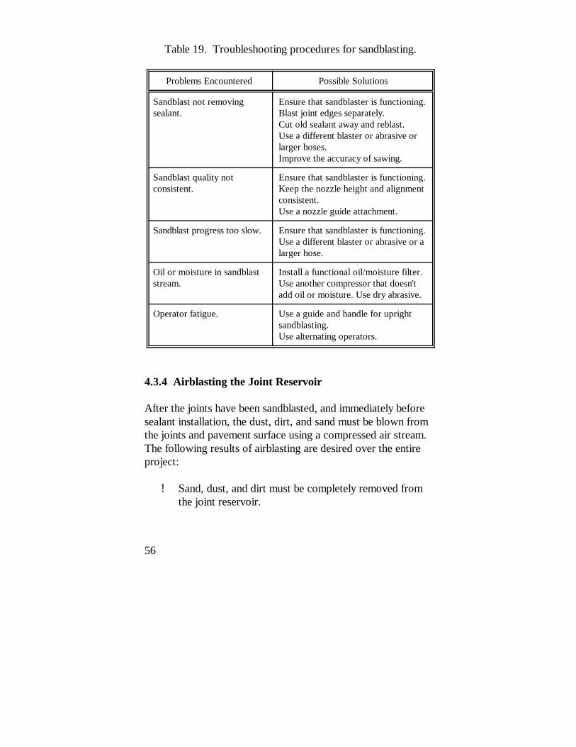
Table 19. Troubleshooting procedures for sandblasting.
Problems Encountered Possible Solutions
Sandblast not removingsealant.
Ensure that sandblaster is functioning.Blast joint edges separately.Cut old sealant away and reblast.Use a different blaster or abrasive orlarger hoses. Improve the accuracy of sawing.
Sandblast quality notconsistent.
Ensure that sandblaster is functioning.Keep the nozzle height and alignmentconsistent.Use a nozzle guide attachment.
Sandblast progress too slow. Ensure that sandblaster is functioning.Use a different blaster or abrasive or alarger hose.
Oil or moisture in sandblaststream.
Install a functional oil/moisture filter.Use another compressor that doesn'tadd oil or moisture. Use dry abrasive.
Operator fatigue. Use a guide and handle for uprightsandblasting.Use alternating operators.
4.3.4 Airblasting the Joint Reservoir
After the joints have been sandblasted, and immediately beforesealant installation, the dust, dirt, and sand must be blown fromthe joints and pavement surface using a compressed air stream. The following results of airblasting are desired over the entireproject:
! Sand, dust, and dirt must be completely removed fromthe joint reservoir.
57
Figure 15. Airblasting operation.
! Any sand, dust, and dirt that may recontaminate thejoints must be removed from the surrounding pavementsurface.
In general, joints should be airblasted immediately prior tobacker rod installation. The airblasting, rod placement, andsealant installation operations must occur on the same day. Ifrain or dew recontaminate the joints, they must be sandblastedand airblasted again after drying.
Successful airblasting methods for accomplishing the aboveresults are as follows:
1. Use approved air compressors, safety equipment, andsafety procedures, as described in section 3.9.4.
2. Hold the nozzle no more than 50 mm from the pavementsurface, as shown in figure 15.
3. Blow debris in front of the nozzle. Do not walkbackwards.
58
4. Make slower or repeated passes until the joint reservoiris completely clean.
5. Elevate and fan the nozzle across the pavement on thelast pass to remove debris from the joint area to a placewhere it cannot recontaminate the joints.
The most common problems encountered in airblasting arerelated to contamination of the air stream or lack of air volumeand pressure. Joint seal materials will not adhere well to dirty ordamp joints. Methods for addressing these problems aredescribed in table 20.
If the joints are slightly damp, a heat lance may be used to drythe joints prior to installing backer rod (Mildenhall, n.d.). Theextreme temperatures that a heat lance can produce (820 to1,650oC) can severely spall concrete pavement that is exposed tothe heat for more than a very short length of time. Extreme caremust be taken to keep the heat lance from remaining in onelocation for more than 1 to 2 s. Pavement that is saturated mustbe allowed to dry before resealing. A heat lance may dry thesurface of such a pavement for a short time, but capillary actionin the concrete will bring the moisture back to the joint veryquickly.
Table 20. Troubleshooting procedures for airblasting.
Problems Encountered Possible Solutions
Oil in airstream. Ensure oil/moisture filter is functional.Clean or replace the hose.
Moisture in airstream. Ensure that oil/moisture filter isfunctional.
Air not removing dust, dirt,and sand.
Use a larger compressor.Use a larger diameter hose.Reduce the diameter of the nozzleopening.
59
4.3.5 Installing Primer
To effectively and economically prime joint surfaces, the primerinstallation process must achieve the following:
! Primer must very thinly and uniformly coat all jointsurfaces to which sealant must bond.
! Primer should not be wasted by applying thick coats orcovering non-essential concrete surfaces.
Primer can be installed using a brush or spray equipment. Sprayequipment is much more efficient, generally resulting in a thinnercoat, and spray nozzles can be designed to coat only the upperjoint wall surface. It is critical that the primer be allowed to dry,since as it dries, it gives off gas (ACI, 1990). If hot-appliedsealant is installed before the primer has dried, bubbles will formin the sealant as the gas tries to escape.
All required operator safety equipment must be used. This mayinclude goggles, gloves, protective clothing, and respirators. Manufacturers' recommendations for installation methods andsafety procedures must be followed.
4.4 Material Preparation and Installation
Objective: To properly install backer rod in clean jointchannels and to adequately prepare, install, and shape sealantmaterial.
The preparation and sealing operations should be scheduled sothat joints are cleaned and left open a minimum amount of timebefore resealing. Prepared joints that are left open overnightmust be airblasted again and reinspected for cleanliness anddryness. Primer, installed before backer rod installation, must bedry and tack-free. Only a minimum amount of time must be
60
allowed to pass between backer rod installation and sealantplacement.
No matter how good the joint preparation has been, impropersealant installation can result in rapid seal failure. Therefore, themanufacturer's recommendations must be followed regardingminimum placement temperatures, sealant heating temperatures,extended sealant heating, and pavement moisture conditions. Most sealant manufacturers recommend installing sealant whenthe pavement is dry and the air temperature is 4oC and rising. Recommended application temperatures for rubberized asphaltsealants generally range from 185 to 200oC. Hand-held,calibrated infrared thermometers can be used to easily checksealant, air, and pavement temperatures.
Polymers used in some hot-applied sealants are susceptible todamage from overheating and from extended heating. Theallowable time such sealants may remain at applicationtemperature ranges from 6 h to 5 days, depending on the sealantproperties. Check with sealant manufacturers for exact heatingtime and temperature limits.
4.4.1 Installing Backer Rod
Backer rod should be installed immediately after airblasting andimmediately before placing the sealant. Joint reservoirs andpavement surfaces must be completely clean before backer rod isinserted. If unclean joint walls are noted during backer rodinstallation, they should be marked for recleaning.
The backer rod serves two purposes. It helps keep the sealant atits design thickness, and it keeps sealant from bonding to thebottom of the joint reservoir. Both thicker sealant and bondingto the reservoir bottom place additional stress on the sealant. Toperform properly and reduce sealant stress, the installed backerrod must meet the following requirements:
61
! The backer rod must be compatible with and appropriatefor the sealant.
! Backer rod must be at the depth required in the plans.! No gaps should be evident between the backer rod and
joint walls.! The rod must be compressed in the joint sufficiently that
the weight of uncured sealant or the tooling operation donot force it down into the reservoir before curing.
! The rod must be dry and clean.! The surface of the rod must not be damaged during
installation.! No gaps should form between backer rods that are
butted together in a joint or at a joint intersection.
Many methods have been used to insert backer rod into joints,ranging from poking it in with a screwdriver to using automated,self-guided installation equipment. Using a screwdriver maydamage the surface of the rod and result in bubbles forming inthe sealant. Automated equipment is most effective forcontinuous joints where only one size of backer rod is generallyneeded. The steps for the most commonly used and successfulmethod of installing backer rod are as follows:
1. Have enough rod sizes available to fit all of the jointwidths at the project.
2. Use a long-handled installation tool with a large-diameter central disk that fits into all joints and does notcut or damage the backer rod, as shown in figure 16.
3. Insert one end of the proper size of rod into the end of ajoint.
4. Tuck the rod loosely into the joint and push the rod intothe joint by rolling the installation tool along the joint.
5. Roll over the rod a second time with the installation toolto ensure proper depth.
6. Cut the rod to the proper length, making sure no gapsexist between segments of backer rod.
62
Figure 16. Backer rod installation.
7. In sections where the rod does not fit tightly to the jointwalls, install larger diameter backer rod.
The depth of the installation tool must be slightly greater thanthe required depth of backer rod because the rod compressesslightly when installed (Blais, 1984). Certain rod materials aremore compressible and require additional tool depth.
Stretching and twisting of backer rod must be minimized duringinstallation, since as the material relaxes, gaps may form at jointintersections and result in sealant failure. When transverse andlongitudinal joints are being sealed in one operation, betterresults are obtained if rod is installed in the entire length of thetransverse joints. That rod is then cut at the intersection withlongitudinal joints and the rod is installed in the longitudinaljoints. Possible solutions to common problems encounteredwhen installing backer rod are described in table 21.
63
Table 21. Troubleshooting proceduresfor backer rod installation.
Problems Encountered Possible Solutions
Rod is tearing (slivers formed)when installed.
Use a smaller diameter backer rod.Ensure that installation tool is smooth.
Side gaps are evident or rod isslipping or is easily pusheddown in joints.
Use a larger diameter rod.
Rod depth is inconsistent. Check the installation tool for depth.Repeat passes with the installation tool.
Rod is shrinking in joint. Gaps are forming between rodends.
Do not stretch the rod when installing.Use a larger diameter roller.
If delay occurs before installing the sealant, dirt and sand can beblown into the cleaned joints, or moisture can enter the joints. When dirt has re-entered the joints after the backer rod has beeninstalled, blow out the dirt using a clean, dry, low-pressureairstream, taking care not to force the rod deeper into the joint. Damp or wet backer rod must be removed from the joints andreplaced with dry rod after the reservoir is completely dry andhas been recleaned.
4.4.2 Sealant Installation
When the joints are clean, the backer rod is installed and, if thetemperatures are within the required limits, sealing can begin. Ifrain interrupts the sealing operation, reclean the open jointsbefore installing the sealant. The sealing operation shouldprogress quickly and result in a seal with the followingcharacteristics:
64
! Prevents infiltration of water through the joints.! Remains resilient and capable of rejecting incompressible
materials at all pavement temperatures.! Maintains a tight bond with the sidewalls of the joint.! Has no bubbles or blisters.! Is not cracked or split.! Is well bonded to the joint walls.! Cannot be picked up or spread on adjacent pavement
surfaces by tires or the action of power-vacuum rotary-brush pavement cleaning equipment after the specifiedcuring period.
! Provides a finished exposed joint surface that is non-tacky and will not permit the adherence or embedment ofdust, dirt, small stones, and similar contaminants.
Hot-Applied Sealant
To install hot-applied sealant that successfully meets the aboverequirements, proper heating and installation methods must beused. Suitable cleanup and safety procedures, as described inappendix C, must also be followed to ensure worker protectionand properly functioning equipment.
Heating the Sealant
Hot-applied sealant performance can be significantly changed bythe procedures used to heat and maintain its temperature duringinstallation. Prior to heating sealant, the melter- applicatorshould be checked for the following properties and modified ifnecessary:
! Carbon buildup on the sides of the heating chambershould be removed.
! All temperature gauge sensors should be cleaned andaccurately calibrated.
65
Heating should be scheduled so that the sealant will be at therecommended temperature when the sealing operation is tobegin. During initial heating, the following guidelines should beadhered to:
1. Keep the heating oil temperature no more than 24oCabove the safe sealant heating temperature stated on thesealant packaging.
2. Keep sealant temperatures between the recommendedpouring temperature and the safe heating temperatureprinted on the sealant packaging.
3. Start the agitator as soon as possible.4. Do not hold the sealant at application temperatures for a
long period before using it.
If sealant is heated above the safe heating temperature, it shouldnot be used because rubberized sealants break down and becomevery thin or very stringy when heated above this temperature. The recommended pouring temperature is the temperature of thesealant that will achieve the best performance. If the sealant isinstalled below this temperature, it may cool before it fills thevoids in the concrete, and a poor bond may result. Recommended pouring temperatures vary between sealantmanufacturers and types. Therefore, the pouring and safeheating temperatures of the sealant in use should be obtainedfrom the sealant packaging, and all sealant operators must bemade aware of it. Supervisors and equipment operators can useinfrared sensors to check pouring temperatures at the nozzle.
The procedures listed below should be followed duringinstallation.
1. Check to ensure that the pavement temperature is abovethe minimum recommended installation temperature andabove the dew point.
66
2. Check the temperature of the sealant at the nozzle andadjust the melter controls to obtain the recommendedpouring temperature at the nozzle.
3. Regularly check the sealant temperatures and adjust asnecessary.
4. Watch for carbon buildup on the sidewalls of the heatingchamber. This is a sign of overheating.
5. Do not use sealant that has been overheated or heated foran extended period of time, or that remains tacky andshows signs of breakdown.
Methods of Installation
Trial installation of at least 15 transverse joints should becompleted using the methods scheduled for use in cleaning andinstalling sealant on each project. The sealed trial joints shouldbe inspected after curing and approved or rejected prior tosealant placement. Hot-applied seals can be cut on three sidesafter cooling for a 50-mm length and can be stretched to observematerial and adhesive properties. A similar test can beconducted on silicone and other chemically cured materials aftercuring is complete.
Upon approval, the remaining joints should be cleaned andresealed in the same manner as the trial joints. Sealing shouldbegin only when the air temperature is 8oC and rising and the airtemperature is above the dew point. The following installationpractices are recommended:
1. Pour the sealant with the nozzle in the joint so that thejoint is filled from the bottom and air is not trappedbeneath the sealant.
2. Apply the sealant in one continuous motion while movingthe wand in a way that the sealant flows out behind thewand, as shown in figure 17 (Darter et al., 1985).
67
Figure 17. Hot-applied sealant installation.
3. Apply sealant in one pass, filling the reservoir to therecommended level. If additional sealant is required inlow sections, it should be added as soon as possible. Inform the backer rod installation crew if leaks areoccurring at backer rod joints.
4. Recirculate sealant through the wand into the meltingchamber when not applying sealant.
68
5. Watch for bubbles, areas of sunken sealant, sealant thatremains tacky, and sealant that has not bonded to thejoint walls, and solve these problems as soon as they areidentified. Several solutions are listed in table 22.
6. Use equipment and installation practices that result inconsistent sealant thickness, little waste, and lowoperator fatigue. Support plates on the wand tip may beuseful for this purpose.
7. Do not allow construction equipment or vehicle trafficonto the pavement until the sealant has set and there isno danger of tracking or stone intrusion.
Cleanup Requirements
Follow the melter–applicator manufacturers' instructions as tothe frequency of cleaning. If carbon is built up on the heatingchamber walls, remove it completely by scraping and flushing. Flush the pump and hose with solvent, if recommended, andwaste the first 10 L of the day to remove any traces of solvent. Dispose of the wasted sealant/solvent solution properly.
Safety Precautions
Obtain the MSDS’s for each sealant material and follow theworker protection and disposal instructions outlined in them. Several safety precautions should be followed before, during,and after installation. These include the following:
1. Be careful when loading blocks of sealant— splashing canoccur.
2. Have operators wear protective gloves and clothing. Sealant and oil temperatures can reach 200oC and cancause serious burns.
69
Table 22. Troubleshooting procedures for hot-appliedsealant installation.
ProblemEncountered
Possible Causes
Possible Solutions
Bubbles insealant
Reaction with backerrod.
Use nonreactive backerrod.
Damaged backer rod. Change the rodinstallation method orrod diameter.
Moisture in joint. Allow the joints to dry. Install sealant abovethe dew point.
Bubbles in melter. Add sealant material. Reduce the agitatorspeed.
Air trapped bysealant.
Fill joints from thebottom.
Sealant isdeeply sunkenin joint
Gap remains betweenrod and wall. Rodslipping into joint.
Use proper diameterbacker rod.
Gap remains betweenbacker rod ends.
Do not stretch rod. Install rod carefully.
Sealant recessis notconsistent
Operator control ispoor. Operatormovement is uneven.Joint width isvariable. Hoses areunmanageable.
Use a nozzle with adepth control plate. Use a wand with ashut-off valve at thenozzle. Use anexperienced operator. Provide a hose support.
70
Table 22. Troubleshooting procedures for hot-appliedsealant installation (continued).
ProblemEncountered
Possible Causes
Possible Solutions
Sealant is notsticking toconcrete walls
Joint walls are notclean.
Remove all old sealant,oil, dust, dirt, sawingslurry, and othercontaminants.
There is moisture onthe walls from rain,dew, or condensate.
Wait for concrete todry. Install above thedew point temperature.
Sealant temperature istoo low.
Maintain recommendedsealant temperature. Insulate and heathoses.
Pavement temperatureis too low.
Wait for warmerconditions. Insulateand heat hoses.
Sealantremains tackyafterinstallation
Kettle contaminatedwith asphalt, heattransfer oil, solvent,or other sealant.
Remove and replacewith fresh sealant. Check meltertemperatures.
71
3. Do not overheat the sealant— it is flammable.4. Make sure the appropriate hoses (manufacturer
recommended) are used.5. Follow manufacturers' safety instructions when using
coal tar compounds. Excessive breathing of fumes orskin contact with coal tar compounds may causeirritation (ACI, 1990).
6. Follow disposal instructions for cleaning solvent andwasted sealant.
Cold-Applied Sealant
Several types of sealant are installed without heating. Theseinclude polysulfides, polyurethanes, and silicones. Consultmanufacturers' literature for installation recommendations foreach sealant type. The discussion in this manual is limited to theinstallation of one-part, cold-applied sealants.
Loading Sealant in Pumping Apparatus
Typically, silicone sealant is pumped from storage containersthrough compressed-air-powered pumping equipment to a wandwith an application nozzle, as shown in figure 18. The sealant ispumped from 19-L buckets or 208-L drums. Two importantprecautions should be observed when loading silicone into anapproved pumping apparatus.
! Load the sealant in the apparatus in a manner that keepsbubbles from becoming trapped in the sealant.
! Limit the exposure of the sealant to air and moisture. Premature curing can result from such exposure.
Methods for Installation
The following practices have been used successfully and arerecommended for installing silicone sealants:
72
Figure 18. Silicone sealant installation.
1. Pour the sealant with the nozzle in the joint, so that thejoint is filled from the bottom and air is not trappedbeneath the sealant.
2. Use a nozzle that applies sealant at a 45o angle, and pushthe bead along the joint rather than draw it with the gunleading.
3. Apply the sealant in one continuous motion, movingsteadily along the joint, so that a uniform bead is appliedwithout dragging, tearing, or leaving unfilled joint space(USAF, 1983).
4. Adjust the pump rate, nozzle type, and nozzle diameterto control the speed of application.
5. Tool (i.e., form a concave surface in) the non-self-leveling sealant using a piece of oversized backer rod,plastic tubing on a fiberglass rod, a dowel, or othersuitable instrument.
73
6. When tooling is required, press the sealant around thebacker rod, forming a uniform concave surface with nowasted sealant on the pavement surface. The bottom ofthe concave tooled surface should be at least 7 mmbelow the pavement surface.
7. The surface of the self-leveling silicone sealant must berecessed 7 to 10 mm below the pavement surface andshould never be exposed to traffic wear.
8. Watch for bubbles, sunken sealant, a non-uniformsurface, and other installation deficiencies, and solvethese problems as soon as they are identified. Severalsolutions are listed in table 23.
9. Allow non-self-leveling sealant to become tack free andself-leveling sealant to skin over before opening thepavement to traffic. If large pavement deflections areexpected, allow a longer cure time.
Non-self-leveling silicone sealant is generally tack free within 90minutes at temperatures above 4oC, and it cures within 7 days. Self-leveling silicone sealant typically skins over within 60minutes and cures in about 21 days.
Cleanup Requirements
Cleaning of the applicator equipment apparatus will be requiredif the sealant begins to cure in the pump or hose. Follow thesealant pump manufacturer’s instructions for cleaning frequencyand required solvents.
74
Table 23. Troubleshooting procedures for cold-appliedsealant installation.
ProblemEncountered
Possible Causes
Possible Solutions
Sealant is notsticking toconcrete walls
Joint walls are notclean.
Remove all old sealant,oil, dust, dirt, sawingslurry, and othercontaminants.
Moisture remains onthe walls from rain,condensate, or dew.
Wait for concrete todry. Install above thepavement dew pointtemperature.
Tooling wasinadequate.
Use more tooling care. Use another strike-offtool.
Sealant isdeeply sunkenin joint
Gap between rod andwall. Rod is slippinginto joint.
Use larger diameterbacker rod.
Gap between backerrod ends.
Do not stretch rod. Install rod carefully.
Installedsealantcontainsbubbles
Reaction with backerrod.
Use nonreactive backerrod.
Damaged backer rod. Change rod installationmethod, tool, or roddiameter.
Bubbles in pumplines.
Set the pumpdiaphragm into sealantbetter.
Air was trapped bythe sealant.
Fill the joint from thebottom.
75
Table 23. Troubleshooting procedures for cold-appliedsealant installation (continued).
ProblemEncountered
Possible Causes
Possible Solutions
Sealant recessis notconsistent
Operator control ispoor. Operatormovement is uneven. Joint width isvariable.
Use a moreexperienced operator. Use a “dog leg”applicator.
Nozzle tip is wrongsize.
Reduce nozzle tip sizeto easily insert to top ofbacker rod.
Surface tooling ispoor.
User more tooling care. Use another strike-offtool (large backer rod,plastic or rubber tubingon flexible handle).
77
%Leff ' 100 & %Lfail Eq. 9
5.0 Evaluation of Joint Seal Performance
Monitoring the performance of joint seal treatments is goodpractice, and it can be done rather quickly (in 1 or 2 h) with fairaccuracy. At least one inspection should be made after the firstwinter, and subsequent evaluations should be conducted atregular intervals to chart the rate of failure and plan forsubsequent maintenance. A mid-winter evaluation is highlyrecommended, since at that time, joints will be near theirmaximum opening and, as a result, adhesion loss can be seenmore easily. Visual evaluation, alone or in conjunction with theIA-VAC joint seal tester, can provide seal performanceinformation. The IA-VAC system can easily determine joint sealeffectiveness in a consistent manner any time of the year untilfailure rates become moderate or greater (Steffes, 1993). Visualevaluation methods will become more necessary as failure ratesincrease.
As discussed in section 2.1, a small representative sample of thepavement section should be selected for the evaluation. Resistance to the entrance of water and debris to the joint shouldbe measured by noting the percentage of water resistance lossusing equation 1 provided earlier. The joint seal effectivenesscan then be calculated using the following equation:
where: %Leff = Percent joint seal effectiveness.%Lfail = Percent length allowing water to enter
joints.
After a few inspections, a graph of seal effectiveness versus timecan be constructed, such as the one in figure 19.
78
A minimum allowable effectiveness level, commonly 50 percent,will help to indicate when additional joint seal treatment isrequired. For example, a resealing plan using figure 19 couldinclude immediate resealing of sites G, H, and I. A budget forresealing in the next 2 years could be prepared for sites E and F. Moreover, estimates of the time to 50 percent effectivenesscould be obtained for planning the resealing of the remainingsites.
Figure 19. Example joint seal deterioration chart(See next page)
0
10
20
30
40
50
60
70
80
90
100
0 10 20 30 40 50 60 70 80
Times, months
Seal
eff
ectiv
enes
s, %
join
t len
gth
Site ASite BSite CSite DSite ESite FSite GSite HSite I
79
Appendix A
Material Testing Specifications
Material testing specifications are listed in tables A-1 and A-2. These specifications are based on specifications prepared by theAmerican Society for Testing and Materials (ASTM), theAmerican Association of State Highway TransportationOfficials (AASHTO), and by States having significant jointresealing experience. Specifications are revised frequently, andthe sponsoring society should be contacted to obtain the latestedition. Information regarding the availability of specificationscan be obtained from the agencies listed below.
ASTM SpecificationsAmerican Society for Testing and Materials100 Barr Harbor DriveWest Conshohoken, PA 19428610-832-9500www.astm.org
AASHTO SpecificationsAmerican Association of State Highway and TransportationOfficials444 North Capitol Street, NW, Suite 249Washington, DC 20001202-624-5800www.aashto.org
U.S. Federal SpecificationsNational Technical Information Service5285 Port Royal RoadSpringfield, VA 22161800-553-6847www.ntis.govwww.fhwa.dot.gov
80
Table A-1. Rubberized asphalt specifications.
Test Description a
Test Criteria
Other Standard Low Modulus
ASTMD 1190
AASHTOM 173
ASTM D 3405
AASHTOM 301
FederalSS-S-1401
StateSpecification
Cone penetration (25oC,dmm)
< 90 < 90 < 90 < 90 < 90 110 to 150
Flow (60oC, mm) < 5 < 5 < 3 < 3 < 3 < 3
Resilience (25oC, %recovery)
> 60 > 60 > 60 > 60
Bond (-18oC, 50% ext.) Pass 5 cycles
Pass5 cycles
Bond (-18oC, 100% ext.)or(-29oC, 50% ext.)
Pass3 cycles
Bond (-29oC, 100% ext.)or (-29oC, 200% ext.)
Pass3 cycles
Pass 3 cycles
Pass3 cycles
Asphalt compatibility Pass
Cone penetration (-18oC,dmm)
> 40
a 1 dmm = 0.1 mm
81
Table A-2. ASTM D 5893 silicone sealant specifications.
Test DescriptionTest
MethodSilicone Type a
Non-Sag Self-Leveling
Rheological properties ASTM D 2202
<7.6 mmslump
Type 1,smooth
Extrusion rate, mL/min ASTM C 1183
> 50 > 50
Tack-free time, h ASTM C 679
< 5 < 5
Bond (-29oC, 100% ext.,immersed, non-immersed, oven-aged)
ASTM D 5893
Pass Pass
Hardness (-29oC, typeA2)
ASTM C 661
< 25 < 25
Hardness (23oC, typeA2)
ASTM C 661
> 30 > 30
Flow ASTM D 5893
No flow No flow
Ultimate Elongation, %
ASTMD 412(C)
> 600 > 600
Tensile stress at 150%strain (23oC), kPa
ASTM D 412(C)
< 310 < 310
Accelerated weathering(500 h)
ASTM C 793
Pass Pass
Resilience, % ASTM D 5893
> 75 > 75
a 21-day cure time.
83
Appendix B
Sample Cost-Effectiveness Calculations
Sample worksheets for cost-effectiveness calculations arepresented in this section. The forms included in section 3.11are used to illustrate the method discussed in that section. Dataused for calculation of cost-effectiveness are listed below and intables B-1 through B-3.
Using an ASTM D 3405 sealant that costs $1.10/L and lasts 5years, together with the same preparation methods listed aboveand a shape factor of 1:1, the computed average annual cost is:
89
Appendix C
Material and Equipment Safety Precautions
Mandated highway safety attire, such as vests and hard hats,should always be worn by crews and supervisors during sealingoperations. In addition, individual crews should be made awareof all safety precautions associated with the materials andequipment with which they are working.
C.1 Materials
In order to protect the health and well-being of maintenanceworkers who handle the various sealant materials, MSDS’sshould be obtained from the manufacturers of all materials to beinstalled, and these sheets should be reviewed by those handlingthe materials. These sheets provide important informationabout health hazards, fire and explosion data, reactivity data,and safe usage and disposal. Every effort should also be madeto determine the type of sealant material to be removed and toaddress any safety hazards that it may present.
C.1.1 Hot-Applied Sealants
Hot-applied sealants require that several safety precautions befollowed:
1. Be careful when loading blocks of sealant— splashingmay occur.
2. Have operators wear protective gloves and clothing. Sealant and oil temperatures can reach 200oC and cancause serious burns.
3. Do not overheat the sealant— it is flammable.
90
4. Follow manufacturers' safety instructions when usingcoal tar compounds. Excessive breathing of fumes orskin contact with coal tar compounds may causeirritation or possibly more serious health problems.
5. Use care with any solvents required for cleanup. 6. Dispose of diluted or wasted sealant as specified in the
MSDS.
C.1.2 Cold-Applied Sealants When working with cold-applied sealants, care should be takento protect workers from skin, eye, or internal contact withsealant materials. MSDS and the manufacturer'srecommendations should be consulted to determine specificsafety requirements for each sealant material.
91
Appendix D
Inspection Checklists for Construction
This section is intended for use by inspectors of resealingprocesses, as well as by supervisors and contractors. Itcontains discussions of planning, equipment, and procedurescritical to the successful completion of a resealing project. Checklists pertaining to each step of the process, includingplanning, equipment, material preparation, joint preparation,sealant installation, final inspection, and safety precautions, areincluded.
Field experience has shown that each step in the resealingprocess requires careful supervision and inspection. Aninspector must continually observe the various operations toensure that proper procedures are being performed. In mostcases, it is the contractor's responsibility to effectively clean andreseal the joints, and it is the inspector's responsibility tocontinually monitor the work and ensure that corrections aremade if requirements are not met.
D.1 Preconstruction Plans and Specifications
Plans must be prepared and distributed to the inspectors and thesupervisors of the installation crew. It is recommended that theinspectors and the construction supervisors meet before workbegins to discuss the plans and specifications. Information thatmust be contained in the plans includes the following:
G 1. Project layout, including stationing and slablengths.
92
G 2. Original joint reservoir dimensions, includingexisting variability.
G 3. Original sealant material type.G 4. Location and type of required pre-resealing
Specifications may be based on adherence to designatedprocedures, on achieving a quality end product, or acombination of the two. Information that must be contained inprocedure-based specifications includes the following:
G 1. Lot testing requirements.G 2. Delivery and storage requirements.G 3. Repair methods and materials for pre-resealing
If end-result specifications are used, the following informationmust be included:
G 1. Lot testing requirements.G 2. Delivery and storage requirements.G 3. Repair methods and materials for pre-resealing
repairs.G 4. Required results of each preparation procedure
and acceptance/rejection criteria.
93
G 5. Required results of the installation process andacceptance/rejection criteria.
G 6. Weather condition limitations.G 7. Limitations of traffic shutdown.G 8. Safety requirements.G 9. Material disposal requirements.
An example of installation acceptance criteria is included insection D.4. In most cases, a combination of procedure-basedand end-result specifications is used, and the followinginspection process is based on a combination of the two.
D.2 Equipment Inspection
All equipment must be inspected and approved before theproject begins, as well as during joint preparation and sealantinstallation. A list of proposed equipment should be submittedfor approval before installation. During pre-installationinspection, the inspector should check all equipment to be usedon the project, making sure that each piece meets therequirements of the project specifications or the suggestedrequirements listed previously in table 11. If questions ariseabout the suitability of the equipment, a statement from thesealant manufacturer should be supplied, indicating that theequipment is acceptable for installing the sealant.
The condition and effectiveness of each piece of equipmentshould be checked during trial installation and at the beginningof each day of preparation and installation. Criteria forequipment effectiveness are listed in the sections below.
94
D.3 Field Installation Inspection
After all required spall repair, load transfer restoration, slabstabilization, grinding, and other rehabilitation have beencompleted and approved, the resealing process can begin. It isrecommended that the inspectors and supervisors meet beforework begins to discuss the following subjects:
1. Exact locations and number of joints to beresealed (boundaries should be clearly marked).
2. Traffic control requirements and lane closure timelimitations.
3. Methods required for cleaning and resealing joints(if procedure-based specification).
4. Criteria for approval of all cleaning and installationequipment and processes.
5. Final criteria for approval of resealing work,including procedures and penalties for rejection.
6. Any localized variations from the specifiedmethods.
7. Safety requirements for all equipment andprocedures (including material disposalrequirements).
8. Procedures in the event of wet or cold weather.9. Procedures in the event that seal quality
requirements are not met.
D.3.1 Inspection of Joint Preparation
Joint preparation, as discussed in this manual, refers to sealantremoval, joint refacing, final cleaning, primer installation, andbacker rod insertion. Sealant manufacturers' instructions shouldbe followed when preparing joints unless noted otherwise in theplans and specifications. The following inspection checklist canbe used to ensure that joint preparation is completed properly
95
(USAF, 1983), although not all of these cleaning processes areused, in many cases.
G 1. Joint plowing:G Plow is removing the required amount of
sealant.G Plow is not spalling the joint edges. G Worker and driver safety are not
compromised.
G 2. Concrete sawing:G Saw is removing the required amount of
concrete and sealant. G Saw is uniformly cutting to the proper width
and depth (depth and width can be checkedquickly using a metal template).
G Saw is refacing both sides of the joint. G All guards and safety mechanisms are
functioning properly.G All sawing slurry is immediately removed
from the joints.
G 3. Waterwashing:G Equipment is removing all sawing slurry and
old sealant from the joints. G No standing water remains in the joints.
G 4. Abrasive blasting:G The nozzle is being held 25 to 50 mm from
the pavement.G Two passes are made for each joint,
directing the nozzle toward one side of thejoint for each pass.
G No old sealant, oil, or dried sawing slurryremains on the joint walls.
96
G The blaster does not introduce oil ormoisture to the joint.
G The operator is using all OSHA- or State-required protective devices.
G Following sandblasting, all joint walls exhibitfreshly exposed concrete.
G 5. Airblasting:G Equipment is removing all dirt, dust, and
sand from the dry joint reservoir. G The airblaster does not introduce oil or
moisture to the joint (check for oil bydirecting the airstream onto a tire or a pieceof paper and noting any discoloration).
G The operator is wearing required eye and earprotection.
G Following airblasting, the joint is clean anddry.
G 6. Vacuum or compressed-air cleaning :G Cleaning equipment is removing all old
sealant, sand, dirt, and dust from thepavement surface.
G Debris has no potential for re-entering thejoints, especially on windy days or whentraffic is moving next to the cleaned joints.
G 7. Primer application:G Primer applicator is applying a thin layer of
sealant uniformly over joint faces to receivesealant.
G All required safety protection equipment is inuse and is operational.
G Primer is allowed to dry before backer rod isinserted.
97
G 8. Backer rod installation:G The rod is inserted into the joint uniformly to
the required depth without stretching ortearing it. Depth can be checked using atemplate (slivers of rod in the joint indicatethat the rod is too large).
G The rod remains tight in the joint withoutgaps along the sides, at joint intersections, orbetween rod segments.
G The rod is compressed in the joint enoughthat the weight of the uncured sealant or installation equipment or tooling equipmentwill not force it down into the joint.
G A larger diameter rod is used in wide jointsections.
G 9. Low-pressure air cleaning :G When needed, all dust or dirt that has re-
entered clean joints that contain backer rodis blown out.
G The backer rod is not pushed into the jointby the airstream.
Water on the joint walls during sealing will severely reduce theability of the sealant to bond to the walls and can result inbubbles in some sealants. Check frequently for dew that maycollect in the joints and remain after the surface is dry,particularly if temperatures and humidity levels have been at ornear the dew point. If cleaned joints are recontaminated byrain, dew, dirt, or oil, they should be recleaned in a manner thatrestores cleanliness. This may require sandblasting andairblasting or merely airblasting. Cleaned joints that are leftovernight should, at a minimum, be airblasted again. Moistbacker rod should be replaced after drying and joint recleaning.
98
One method that an inspector can use to communicate the needfor additional preparation at a particular joint is to mark near itwith a particular color of paint (USAF, 1983). A possiblepattern that could be used is the following.
1. Yellow— Repairs must be made to joint beforesealing.
2. Orange— Joint is not the proper size.3. Red— Joint is not properly cleaned.4. Blue— Backer rod is not tight or is not at proper depth.5. Brown— Improper sealing technique (too full, too low,
tacky sealant, not tooled correctly, bubbles in sealant,sealant not bonded, etc.).
The contractor or supervisor can use green spray paint toindicate that the problem is repaired and the inspector shouldre-examine the joint for approval.
D.3.2 Inspection of Joint Sealant Installation
The inspector should watch for several items prior to andduring installation of the sealant material. The followingsection is a checklist for inspection of joint sealant installation.
When inspecting the installation of hot-applied sealantmaterials, the information listed below must be determinedbefore heating begins. This information can be obtained fromsealant manufacturers and from the project plans andspecifications:
G 1. The recommended sealant applicationtemperature.
G 2. The safe sealant heating temperature.
99
G 3. The length of time that a sealant can be heatedbefore it begins to break down.
G 4. The required thickness of sealant.G 5. The required sealant recess below the pavement
surface.G 6. The air temperatures allowable for sealing.G 7. The average sealant curing time and the time
before traffic can be allowed on the pavementafter resealing.
G 8. The MSDS’s.G 9. The criteria for acceptance/rejection of resealing
work, and the penalties associated with rejection.G 10. Acceptable test results for all materials to be
installed.G 11. The production date and shelf life of all materials.
During installation of hot-applied sealants, the following itemsshould be regularly checked to ensure that they meet therequirements:
G 1. All joints remain clean and dry.G 2. All backer rods remain tight in the joint at the
correct height with no gaps.G 3. The melter–applicator maintains the sealant at the
required temperature without overheating. G 4. Sealant leaving the nozzle is at the application
temperature. G 5. The agitator is functioning properly. G 6. No carbon is built up on the melting chamber
walls. G 7. All thermometers and temperature controls are
monitored and functioning properly.G 8. The operator is not trapping bubbles in the sealant
or overfilling or underfilling the joints.G 9. Spilled sealant is removed from the pavement
surface.
100
G 10. Areas of low sealant are not present or are quicklyfilled. Steps are taken to eliminate the cause ofthe low sealant.
G 11. All required operator safety equipment is in use. This applies especially to D 3406 materials.
Warning: If white smoke is seen rising from the kettle, stopthe operation immediately and check the sealant temperature. If the sealant remains tacky in the joint long after placement, orthe sealant becomes stringy inside the melting chamber, thesealant has been overheated and should be completely removedfrom the chamber and wasted.
D.3.2.2 Silicone Sealant Installation Inspection
Prior to installation of silicone sealants, the followinginformation should be obtained by the inspector:
G 1. The expiration date of the sealant material.G 2. The air temperatures allowable for sealing.G 3. The required thickness of sealant.G 4. The required sealant recess below the pavement
surface.G 5. The need for tooling the surface of the sealant.G 6. The average sealant curing time and the time
before traffic can be allowed on the pavementafter resealing.
G 7. Safety data from the MSDS.G 8. The criteria for acceptance/rejection of resealing
work and penalties for rejection.G 9. The acceptable results of lot tests for all materials.G 10. The production dates and shelf life of all materials.
As sealant installation continues, the following items should beregularly checked for compliance with the plans andspecifications:
101
G 1. All joints remain clean and dry.G 2. Backer rods remain tight in the joint at the correct
height with no gaps.G 3. The silicone applicator system is not introducing
bubbles to the sealant. G 4. The applicator, wand, and controls allow the
operator to fill the joint uniformly to the correctlevel.
G 5. The operator is not trapping bubbles in the sealant.G 6. The operator is not overfilling or underfilling the
joints (sealant thickness and recess can be checkedby inserting a thin ruler through the uncuredsealant to the top of the backer rod).
G 7. Non-self-leveling silicone sealant is tooledimmediately, forcing sealant against the joint wallsand creating a smooth concave surface.
G 8. Any sealant that remains on the pavement surfaceis removed.
G 9. Areas of low sealant are not present or are quicklyfilled. Steps are taken to eliminate the cause of thelow sealant.
G 10. All required operator safety equipment is in use.G 11. Traffic is not allowed on the pavement until the
sealant is skinned over and cannot be damaged.
D.4 Final Inspection
During installation and prior to approval, the resealed jointsshould be individually inspected, ensuring that the sealant meetsthe following criteria, and noting the presence and severity ofany distresses (Darter et al., 1985; USAF, 1983):
102
G 1. Sealant is bonded firmly to the joint sidewalls (cured sealant material should not separate fromthe sidewalls when pulled lightly with thefingertips across the joint).
G 2. Sealant is not tacky after curing and will notpermit adherence of dust, dirt, or small stones.
G 3. Sealant material contains no cracks, bubbles, orblisters.
G 4. Sealant cannot be picked up or spread on adjacentpavement surfaces by tires, rubber-tired vehicletraffic, or the action of power-vacuum rotary-brush pavement-cleaning equipment after thespecified curing period.
G 5. Sealant is resilient and capable of rejecting stonesat high pavement temperatures.
G 6. Sealant is recessed to the correct depth below thepavement surface (this is critical for siliconesealants, as they are not resistant to traffic wear).
G 7. Sealant spilled on the pavement surface has beenremoved.
G 8. No debris remains on the pavement surface.
103
Appendix E
Partial List of Material and Equipment Sources
This section contains information for contacting severalmanufacturers of sealant materials, backer rod, and installationequipment. Addresses and phone numbers are given formanufacturers and suppliers who can provide the inquirer withinformation regarding material properties, recommendedinstallation practices, safety procedures, and local suppliers.
MSDS’s that describe the material components, any hazardousproperties, and any required protective equipment, should beavailable from all sealant manufacturers.
E.1. Sealant Material
E.1.1. Manufacturers of Hot-Applied Rubberized Asphalt Sealant
Crafco Incorporated W.R. Meadows, Inc.6975 W. Crafco Way 300 Industrial Drive, Box 338Chandler, AZ 85226 Hampshire, IL 60140-0338(602) 276-0406 (847) 683-4500(800) 528-8242 (800) 342-5976www.crafco.com www.wrmeadows.com
Koch Materials Company4111 East 37th Street NorthP.O. Box 2338Wichita, KS 67220(316) 828-8399(800) 654-9182www.kochmaterials.com
104
E.1.2. Manufacturers of Self-Leveling and Non-Self- Leveling Silicone Sealant
Crafco Incorporated Dow Corning Corporation6975 W. Crafco Way P.O. Box 994Chandler, AZ 85226 Midland, MI 48686-0994(602) 276-0406 (517) 496-4000(800) 528-8242 www.dowcorning.comwww.crafco.com
E.2. Backer Rod Material
E.2.1. Manufacturers of Expanded Closed-Cell Foam Rod
Adhesion failure–Complete loss of bond between a sealantmaterial and the concrete joint wall.
Allowable extension–The amount of stretching of a sealantmaterial under which performance is estimated to beadequate.
Average daily traffic (ADT)–The total traffic volumecarried by a pavement during a given period (in wholedays), greater than 1 day and less than 1 year, dividedby the number of days in that period.
Blowups–The result of localized upward movement orshattering of a slab along a transverse joint or crack.
Channel face–The vertical concrete sidewall of a sawedjoint sealant reservoir.
Compression seals–Preformed seals, generally made fromneoprene, that can be compressed and inserted intoconcrete joints for sealing purposes.
Corner break–A diagonal crack forming between transverseand longitudinal joints that extends through the slab,allowing the corner to move independently from the restof the slab.
D-cracking–The breakup of concrete due to freeze-thawexpansive pressures within certain susceptibleaggregates (also called durability cracking).
108
Embedment–To become fixed firmly in a surroundingmass, as stones sink into and become fixed in softsealant material.
Extruded–Forced through a die to give the material acertain shape.
Flow–The sinking of unstable sealant into a sealantreservoir.
Horizontal movement–Opening and closing of jointsresulting from pavement expansion and contraction.
Incompressible material–Material that resists compression,such as stones, sand, and dirt in a crack or jointreservoir that is closing.
Joint growth–The gradual increase in joint width resultingfrom the filling of joints with incompressible materialsduring cold cycles.
Joint sidewalls–The vertical concrete edges of a sawedjoint reservoir.
Life-cycle cost analysis (LCCA)–An investigation of thepresent and future costs of each repair alternative,taking into account the effects of both inflation andinterest rates on expenses over the life of the project.
Load transfer–The transfer of load across a joint or crackin concrete pavement resulting from aggregateinterlock, dowels, or other load-carrying devices.
109
Overbanding–Spreading a thin layer of sealant (about 38 mm wide) onto a pavement surface centered over a joint or crack at the same time that the sealant reservoir is filled.
Pumping–The ejection of water and fine materials frombeneath a concrete pavement through cracks or jointsunder pressure from moving loads.
Refacing–Removing about 1 to 2 mm of concretefrom each wall of a sealant reservoir using diamond sawblades.
Resealing–Replacing sealant in joints or cracks, preferablyusing good-quality methods and materials.
Sealant/channel interface–The vertical edge of a sealedjoint where sealant material and concrete joint facemeet.
Sealant reservoir–The channel along a joint or crack thathas been widened by sawing to allow sealant to beplaced in it.
Sealant system–All components that function to seal joints(i.e., sealant material, surrounding concrete, andsealant/concrete interface).
Slurry–The mixture of water, concrete dust, old sealant,and dirt that results from resawing a joint in concretepavement.
Subdrainage–Drainage of moisture from beneath apavement by means of a porous subbase materialconnected to outlet drain lines.
110
Track–The spreading of unstable sealant material along thepavement surface by traffic tires.
Undersealing–Filling voids beneath a concrete pavementusing a pressurized slurry or hot asphalt material.
Vertical shear–Vertical stress along the sealant/concreteinterface resulting from traffic loading, curling, orpavement faulting.
Weathering–Breakdown of sealant material resulting fromthe effects of moisture, ultraviolet rays, and time.
111
References
American Concrete Institute (ACI). 1990. Guide to SealingJoints in Concrete Structures, American Concrete InstituteReport ACI 504R-90.
Blais, E.J. 1984. Value Engineering Study of Crack and JointSealing, Federal Highway Administration Report FHWA-TS-84-221.
Bodocsi, A., I.A. Minkara, and R.S. Arudi. 1993. “Analysis ofHorizontal Movements of Joints and Cracks in Portland CementConcrete Pavements,” Transportation Research Record 1392.
Bugler, J.W. 1983. "Problems and Solutions in Rigid PavementJoint Sealing," Public Works.
Carpenter, S.H., M.R. Tirado, E.H. Rmeili, and G.L. Perry.1987. Methods for Shoulder Joint Sealing, Vol. 1:Serviceability Requirements, Federal Highway Administration,Washington, D.C.
Collins, A.M., W.D. Mangum, D.W. Fowler, and A.H. Meyer.1986. Improved Methods for Sealing Joints in Portland CementConcrete Pavements, Center for Transportation Research,University of Texas at Austin, Research Report 385-1,FHWA/TX-87-385-1.
Darter, M.I., E.J. Barenberg, and W.A. Yrandson. 1985. JointRepair Methods for Portland Cement Concrete Pavements,NCHRP Research Report 1-21. Evans, L.D. et al. 1993. Innovative Materials Developmentand Testing. Volume 1: Project Overview (SHRP-H-352);Volume 2: Pothole Repair (SHRP-H-353); Volume 3: Treatmentof Cracks in Asphalt Concrete-Surfaced Pavements (SHRP-H-
112
354); Volume 4: Joint Seal Repair (SHRP-H-355); Volume 5:Partial-Depth Spall Repair (SHRP-H-356), Strategic HighwayResearch Program (SHRP), National Research Council,Washington, D.C.
Evans, L.D., M.A. Pozsgay, Smith, K.L., and A.R. Romine. 1999. Long-Term Monitoring of SHRP H-106 PavementMaintenance Materials Test Sites, PCC Joint ResealExperiment Final Report, Federal Highway Administration,Washington, D.C.
Mildenhall, H.S., and G.D.S. Northcott. (no date). A Manualfor Maintenance and Repair of Concrete Roads, Department ofTransportation, Cement and Concrete Association.
Smith, K.L. et al. 1991. Innovative Materials and Equipmentfor Pavement Surface Repairs. Volume I: Summary of MaterialPerformance and Experimental Plans (SHRP M/UFR-91-504);Volume II: Synthesis of Operational Deficiencies of EquipmentUsed for Pavement Surface Repairs (SHRP M/UFR-91-505),Strategic Highway Research Program (SHRP), NationalResearch Council, Washington, D.C.
Smith, K.L., M.A. Pozsgay, L.D. Evans, and A.R. Romine. 1999. Long-Term Monitoring of SHRP SPS-4 PavementMaintenance Materials Test Sites, SPS-4 Supplemental JointSeal Experiment Final Report, Federal Highway Administration,Washington, D.C.
Steffes, R.F. 1993. “Innovative Leak Test for Pavement JointSeals,” Transportation Research Record 1392.
United States Air Force (USAF). 1983. Rigid Pavement Designfor Airports, Chapter 7–Standard Practices for Sealing Jointsand Cracks in Airfield Pavements, Air Force Manual 88-6.