Power Meter Installation from
Start to Finish
Metering Project Guide
Metering Project Guide
© 2015 DENT Instruments, Inc. No portion of this document may be reproduced or
distributed without written permission from DENT Instruments.
johndobbie
Esis normal hor.
Contents
Metering Project Guide
Introduction 3
Before the Site Visit 4
At the Project Site 11
Meter Installation 16
Verifying Meter Installation 28
Appendix 37
Metering Checklists 39
3Metering Project Guide
Whether this is your first metering project or you’re a seasoned
facilities manager, it’s important to remember that a little planning
up front can go a long way in making your project easier. By
answering a few questions, the goal, methodology, and other
details fall into place. Take 15 minutes to read through this guide
before starting your next energy metering project.
Let the objectives define the metering. What do you want to learn?
4Metering Project Guide
Before even visiting a project site, there are a number
of basic project questions that need to be answered.
The more detail, the better! The following list is a
good place to start. Keep in mind that each project is
different – some of these questions may not apply to
you, and that’s OK. This is just a general guide to help
you get started.
Before the Site Visit
Which type of load needs to be
monitored?
Examples may be HVAC, lighting, motors,
refrigeration, or processes.
How many loads need to be
monitored?
1. Will there be loads in multiple electrical
panels?
2. Do any of the loads share a common
voltage source?
3. Are the loads spread across multiple
buildings?
5Metering Project Guide
Before the Site Visit
What do you want to learn about
each load?
1. Energy use during a given period: System
kWh
2. System kW/Peak Demand: Load Profile
3. Is the load balanced: Phase Amps
4. Power Factor of the load: System PF
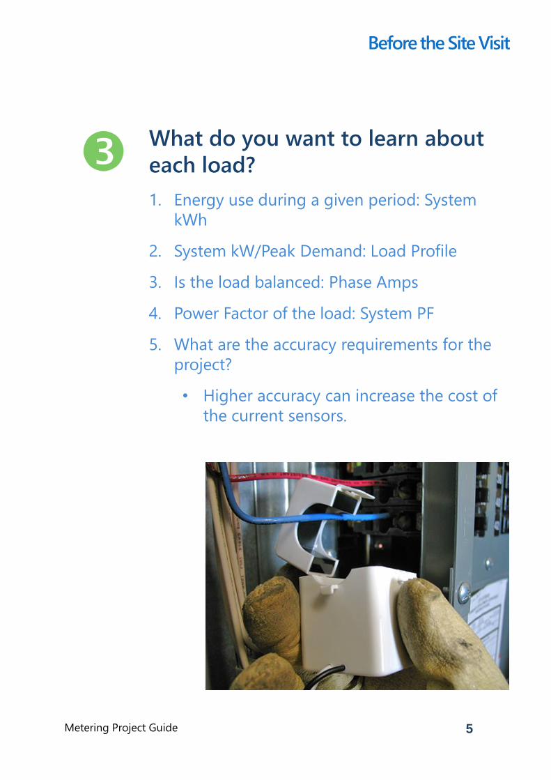
5. What are the accuracy requirements for the
project?
• Higher accuracy can increase the cost of
the current sensors.
6Metering Project Guide
Before the Site Visit
How long will the project run?
Project length can determine the
communication requirements
1. Will remote data retrieval be required?
2. Is an existing network available?
3. Is periodic on-side data downloading
practical?
4. Will Wi-Fi Access Point, Bluetooth, or USB be
used?
5. Can the data retrieval wait until the meter is
removed at the end of the project?
7Metering Project Guide
Before the Site Visit
Is the meter to be connected to a
Building Management System
(BMS)?
If the answer is “yes,” a PowerScout, rather than
an ELITEpro XC may be the appropriate choice.
A PowerScout is designed for permanent
metering and can communicate via the
following methods:
• BACnet
• Modbus
• Ethernet
• RS-485
If your measurement study is temporary in
nature – such as a load study, M&V, or an
energy audit, the ELITEpro XC is the appropriate
choice. If you need help selecting the correct
meter, please contact DENT Instruments.
8Metering Project Guide
Before the Site Visit
Review the building’s electrical line
drawing to determine:
Voltage Service
1. Voltages great than 600VAC will require a
potential transformer (PT)
2. Type of service
• Single Phase
• Split Phase
• 3-Phase WYE
• 3-Phase Delta
Amperage rating of the breaker feeding the
load under measurement
1. Use this answer to determine which CTs to
use
9Metering Project Guide
Before the Site Visit
Install the DENT software and any
necessary communication device
drivers onto the actual laptop to be
used in the field.
To ensure there are no compatibility issues, it’s
best to install any required software ahead of
time. This also gives you a chance to become
familiar with the software before the
installation.
1. If using an ELITEpro XC, install ELOG.
2. If using a PowerScout, install ViewPoint.
10Metering Project Guide
Before the Site Visit
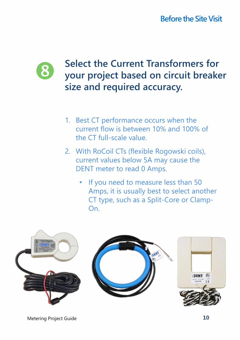
Select the Current Transformers for
your project based on circuit breaker
size and required accuracy.
1. Best CT performance occurs when the
current flow is between 10% and 100% of
the CT full-scale value.
2. With RoCoil CTs (flexible Rogowski coils),
current values below 5A may cause the
DENT meter to read 0 Amps.
• If you need to measure less than 50
Amps, it is usually best to select another
CT type, such as a Split-Core or Clamp-
On.
11Metering Project Guide
Some questions can only be
answered once you’ve visited the
project site. Use your time as
efficiently as possible by working
through the following guide.
At the Project Site
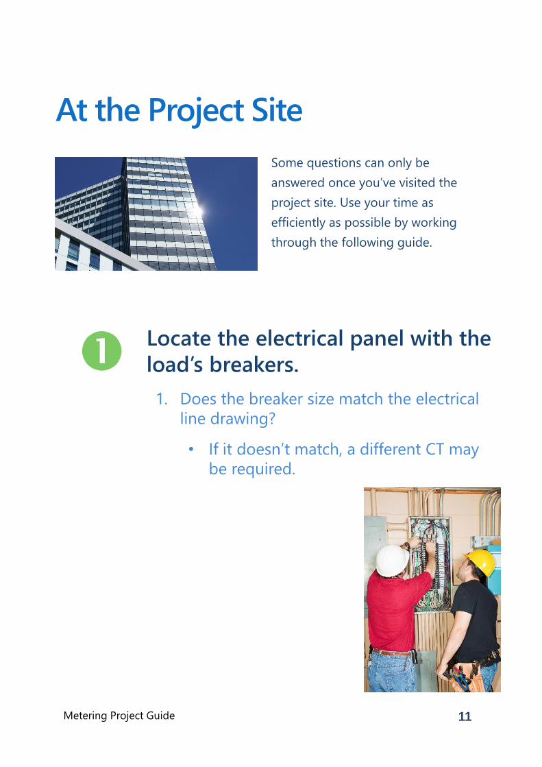
Locate the electrical panel with the
load’s breakers.
1. Does the breaker size match the electrical
line drawing?
• If it doesn’t match, a different CT may
be required.
12Metering Project Guide
Determine where to install the meter.
Keep in mind the length of the
project may help determine the best
choice.
1. Inside the electrical panel
• This is the best option for long-term
measurement studies, especially if
wireless or Ethernet access is available.
• If tampering is a concern, install the
meter inside the panel.
2. Outside the electrical panel
• This choice may be best if the meter is
to be left short-term only and
tampering is not a concern.
• Determine the routing of the wiring to
the meter
• Determine the mounting method
• Decide whether an enclosure is needed
• Even if the meter is installed inside,
dusty or greasy environments may
damage the meter.
• DENT Instruments offers a
“weathertight” drop-in enclosure
for the ELITEpro XC.
At the Project Site
13Metering Project Guide
Determine the communication
implementation. As with installation,
the length of the metering project
may help determine the best choice.
1. Wired Ethernet
• Is existing wiring available?
2. Wireless (Wi-Fi)
• If using the building’s network: Verify
the Wi-Fi signal is strong enough by
connecting the meter to the network.
• If using the meter in Access Point
mode: Verify Wi-Fi communication
works while the meter and computer
are in the final project location.
• If using a meter-only Wi-Fi network:
Determine a location for the Wi-Fi
Access Point/Router near the meters.
• Verify all meters are in range of the
wireless Access Point
• If the meters are not in range, a
second Access Point may be
required.
At the Project Site
14Metering Project Guide
Communication implementation,
continued…
3. Bluetooth
• Determine if the Bluetooth signal is
strong enough for the meter to
connect to the laptop.
• Metal and concrete can create
interference. Try moving the laptop
around for a better signal.
4. USB – Direct Connection
• Examine the local electrical code to
determine if it is legal and feasible to
leave a USB cable hanging outside the
electrical panel for data retrieval.
Always obey all local electrical codes.
At the Project Site
15Metering Project Guide
Verify the breaker actually controls
the load you wish to measure.
1. Check the circuit breaker labeling
2. Determine whether the wire size appears
appropriate
3. If still in doubt:
• Measure the current at the breaker and
at the load to see how they compare
• If the current at the breaker is
higher than the load, the breaker
could either have other loads or it
is not the correct breaker
• If possible, turn the load off and verify
that the current at the breaker drops
the appropriate amount.
• Have another person measure current
at the load and report back. A two-way
radio or cell phone is handy for this
step.
4. Use an AC circuit identifier or tracer with a
high voltage rating to verify the circuit.
At the Project Site
16Metering Project Guide
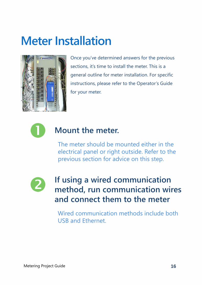
Once you’ve determined answers for the previous
sections, it’s time to install the meter. This is a
general outline for meter installation. For specific
instructions, please refer to the Operator’s Guide
for your meter.
Meter Installation
Mount the meter.
The meter should be mounted either in the
electrical panel or right outside. Refer to the
previous section for advice on this step.
If using a wired communication
method, run communication wires
and connect them to the meter
Wired communication methods include both
USB and Ethernet.
17Metering Project Guide
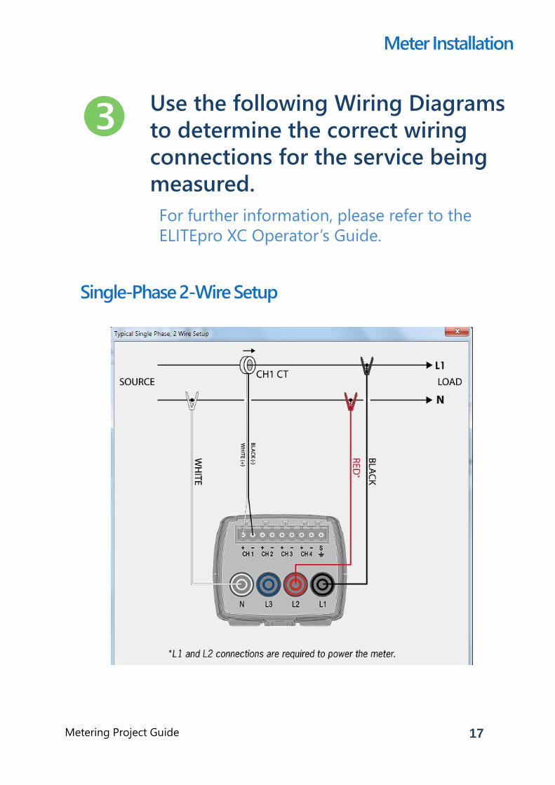
Use the following Wiring Diagrams
to determine the correct wiring
connections for the service being
measured.
For further information, please refer to the
ELITEpro XC Operator’s Guide.
Meter Installation
Single-Phase 2-Wire Setup
18Metering Project Guide
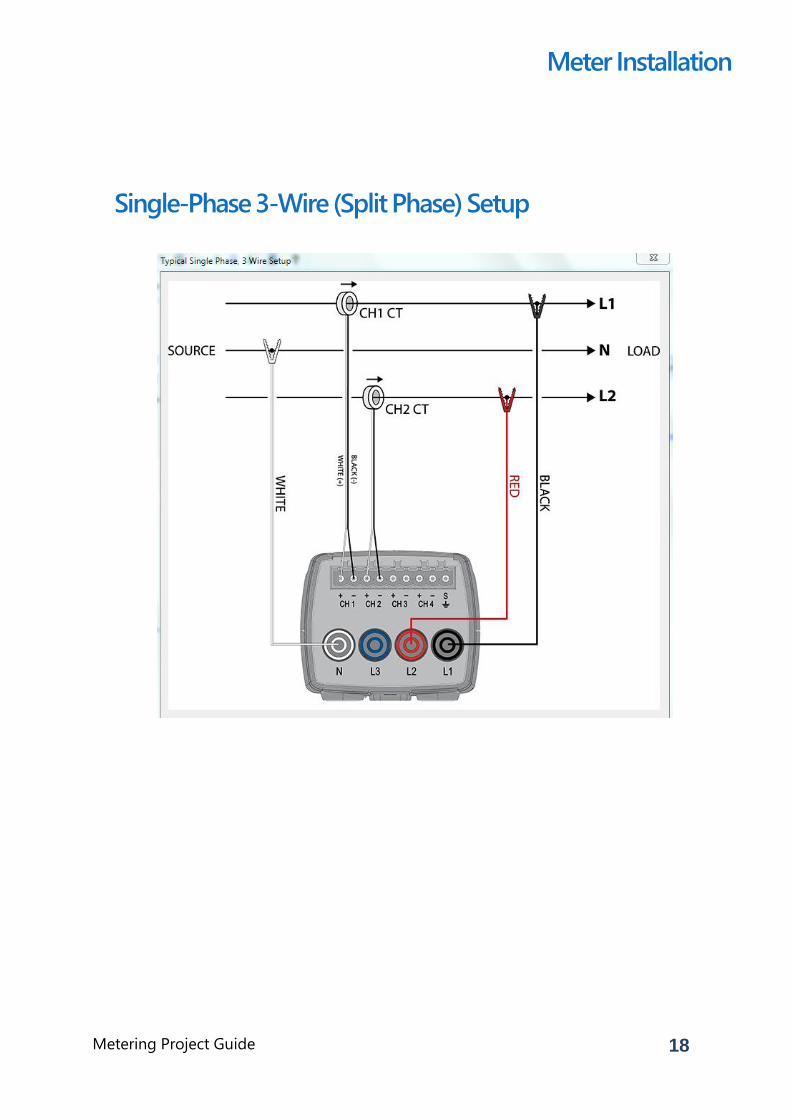
Meter Installation
Single-Phase 3-Wire (Split Phase) Setup
19Metering Project Guide
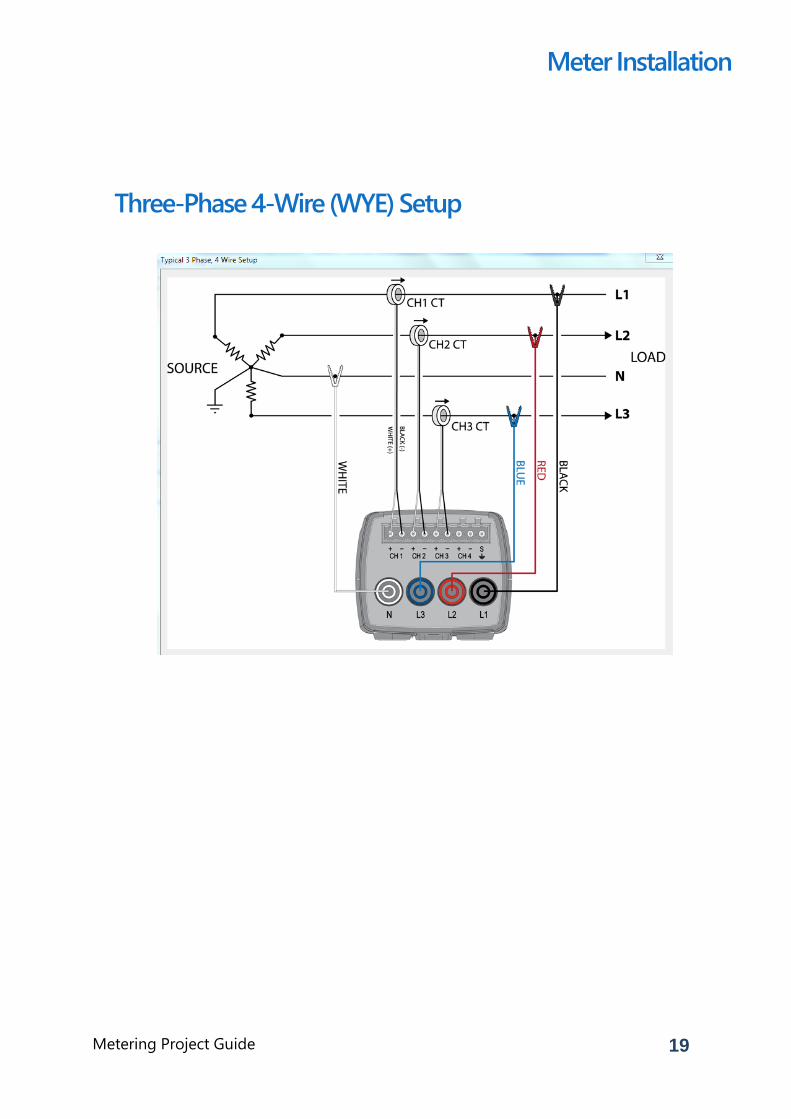
Meter Installation
Three-Phase 4-Wire (WYE) Setup
20Metering Project Guide
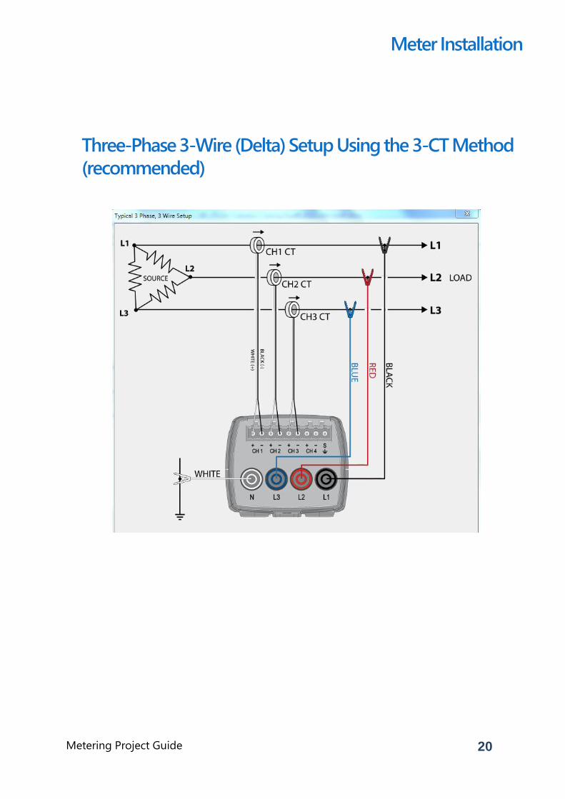
Meter Installation
Three-Phase 3-Wire (Delta) Setup Using the 3-CT Method
(recommended)
21Metering Project Guide
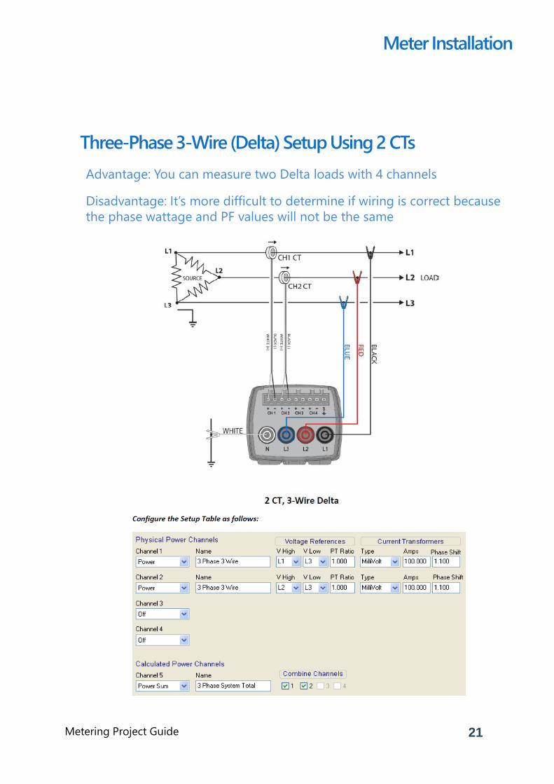
Meter Installation
Three-Phase 3-Wire (Delta) Setup Using 2 CTs
Advantage: You can measure two Delta loads with 4 channels
Disadvantage: It’s more difficult to determine if wiring is correct because
the phase wattage and PF values will not be the same
22Metering Project Guide
Install CTs on the load wires and run
the CT output wires to the meter.
1. Be sure the CTs are connected to the
correct phases.
• The CT must match the Setup Table
configuration in ELOG software.
• For example, if the CT is to be
installed on the CH2 and CH2 is
configured as L2-N (L2=Vhi,
N=Vlo), this CT must be installed
on L2 of the load, otherwise kW,
KVARs, and PF will be INCORRECT.
2. Ensure that all CTs are facing the correct
direction.
• Some CTs point to the Source, while
others point to the Load. Refer to the
labeling on the CT to determine which
direction to face.
• If a CT is installed backwards, kW and
kVAR readings will be negative
Meter Installation
23Metering Project Guide
CT Installation, Continued…
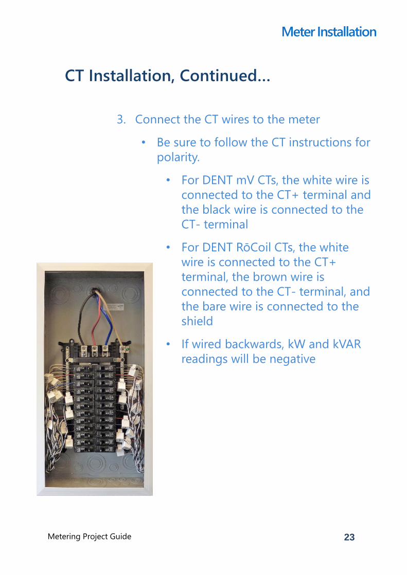
3. Connect the CT wires to the meter
• Be sure to follow the CT instructions for
polarity.
• For DENT mV CTs, the white wire is
connected to the CT+ terminal and
the black wire is connected to the
CT- terminal
• For DENT RōCoil CTs, the white
wire is connected to the CT+
terminal, the brown wire is
connected to the CT- terminal, and
the bare wire is connected to the
shield
• If wired backwards, kW and kVAR
readings will be negative
Meter Installation
24Metering Project Guide
CT Installation, Continued…
4. If running long wire lengths, be sure to
label the wires or use color-coded wires to
help prevent the CTs from being installed
on an incorrect CT channel.
5. Unused current channels can be left open.
It is normal for an unused channel to
measure values.
• If reading values on an unused channel
is not desired, simply short the CT
input with a small wire.
Meter Installation
CT Installation Tips
Note the maximum distance CT leads can be extended.
• RōCoils: 100ft
• Split Cores: 500ft
Parallel CTs to increase the number of monitored circuits:
• CTs must all be on the same voltage phase
• CTs must all have the same amperage rating
• CT value in the SUT =
(Amperage Rating) X (Number of CTs)
25Metering Project Guide
Connect the meter’s voltage inputs
to the load’s voltage source.
1. Wiring the voltage leads on an energized
source is not recommended.
• All DENT meters have a built-in power
supply across L1 and L2. Once L1 or L2
is connected, the other lead will
become energized.
• To avoid shock, disconnect the voltage
leads from the ELITEpro XC so the croc-
clips/voltage lead with banana plug
assembly can be first connected to the
voltage source separately from the
meter.
2. Be certain the voltage source is the same
source that is feeding the load to be
measured.
• There are instances where there are
two transformers feeding a building. In
this case, it’s easy to accidently
connect the voltage leads to the
incorrect transformer.
Meter Installation
IMPORTANT!Always observe safety best practices while working in a panel.
Wear gloves and other protective gear as required.
26Metering Project Guide
Connecting the Meter to Voltage,
Continued…
3. It is best practice to connect the meter’s
voltage inputs to a dedicated circuit
breaker (one that is fed by the same
voltage sources as the load) using bare
wires or croc-clips.
• With the circuit breaker off, connect the
L1, L2, and L3 bare wires or croc-clips
to the breaker and the Neutral wire to
the Neutral buss bar.
4. If a dedicated circuit breaker is not
available, choose a breaker that is
accessible and is fed by the same voltage
source as the load.
• Connect the L1, L2, and L3 croc-clips
(with the wires disconnected from the
meter) to a circuit breaker and the
Neutral wire to the Neutral buss bar.
Connect the banana plugs into the
meter.
Meter Installation
27Metering Project Guide
Power the Meter
1. Setup Table
• Select the correct line frequency
• Select the service type
• Single Phase
• Split Phase
• WYE
• 2 CT Delta
• Select which parameters to log
• Choose a logging interval
2. Verify logging is on
Meter Installation
If the meter wasn’t configured before
the site visit, use ELOG software to
now configure it for the current
project.
28Metering Project Guide
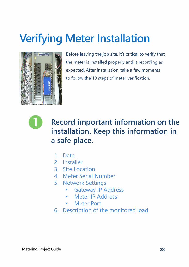
Before leaving the job site, it’s critical to verify that
the meter is installed properly and is recording as
expected. After installation, take a few moments
to follow the 10 steps of meter verification.
Verifying Meter Installation
Record important information on the
installation. Keep this information in
a safe place.
1. Date
2. Installer
3. Site Location
4. Meter Serial Number
5. Network Settings
• Gateway IP Address
• Meter IP Address
• Meter Port
6. Description of the monitored load
29Metering Project Guide
Take pictures of the installation site.
1. Outside the electrical room. This is helpful
for any other personnel who need to
interface with the meter.
2. Inside the electrical room.
3. The meter itself along with CT installation
and voltage connections.
Verifying Meter Installation
Using ELOG software, retrieve the
Setup Table from the logger and
verify that it is correct.
1. Data interval is set (typical is 15 minutes).
2. Vhi and Vlo match the voltage phases the
CTs are installed on.
3. CT type setting matches the CTs used.
4. CT Amp setting matches the CTs used.
5. CT phase shift matches settings outlined in
the Operator’s Guide.
6. Recorded Values are selected as needed for
the project.
30Metering Project Guide
Using ELOG software, verify the
logger’s clock is correct.
1. Check the logger clock by either:
• Viewing Real-Time Values
• Synchronizing time to the PC
• Manually setting the clock
Verifying Meter Installation
Are the PhaseChek LEDs green?
1. If any LEDs are blue, the kW will be
negative. This is most likely caused by the
CT being installed backwards.
2. If any LEDs are red, the PF<0.55. This is
most likely caused by the CTs being placed
on the wrong phase and not matching the
Setup Table. Or, the load’s PF<0.55.
3. If LEDs flash red and blue, this indicates the
CT is on backwards and on the wrong
voltage phase, not matching the Setup
Table.
4. Note: If using the optional Delta 2 CT
Connection, it is common for an LED to
be red when the system PF is <0.87 and
an LED to be blue when the PF<0.5
31Metering Project Guide
Using ELOG software, check Real-
Time values to see if the numbers
make sense.
1. Are the load current and watt
measurements reasonable for the load?
• Example 1: If the current readings
are 12 Amps for a 100 HP motor, the
readings are obviously too low. This
could mean:
• CTs are on the wrong wire
• CT value in the Setup Table is
incorrect
• CT type in the Setup Table is
incorrect
• Example 2: When using RōCoil CTs,
the current reading is zero and the
expected current should be 4 Amps.
This could mean:
• The current is too low to
measure with a RōCoil CT.
RōCoils are designed for high-
current use and readings will
snap to zero on currents below
5 Amps.
Verifying Meter Installation
Note: It is best to
choose a CT in
which the load will
be between 10%
and 100% of the
CT full scale
rating.
32Metering Project Guide
Checking Real-Time Values, Continued…
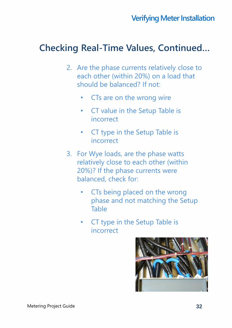
2. Are the phase currents relatively close to
each other (within 20%) on a load that
should be balanced? If not:
• CTs are on the wrong wire
• CT value in the Setup Table is
incorrect
• CT type in the Setup Table is
incorrect
3. For Wye loads, are the phase watts
relatively close to each other (within
20%)? If the phase currents were
balanced, check for:
• CTs being placed on the wrong
phase and not matching the Setup
Table
• CT type in the Setup Table is
incorrect
Verifying Meter Installation
33Metering Project Guide
Checking Real-Time Values, Continued…
4. Are the phase watts positive? If not:
• Most likely the CT is installed
backwards or the wire connection at
the meter is reversed. Check to see if
the CT is installed backwards. If you
do not want to reverse the CT,
reverse the CT wires at the logger
connection.
• Note: It is possible when using the
2-CT method on a Delta load that
one channel/phase can be negative
on loads that have poor PF.
• Note: Negative values could be
correct for co-generation
applications, such as wind or solar,
during power generation.
5. For Wye loads, are the phase PF readings
relatively close to each other when
monitoring a balanced load? If not:
• This is most likely caused by the CT
being placed on the wrong phase
and not matching the Setup Table.
Verifying Meter Installation
34Metering Project Guide
Checking Real-Time Values, Continued…
6. If available, compare to external
references. Readings should match
within a percent or two (no two meters
will read exactly the same).
• Digital Voltmeters (DVM)
• Does the Meter Phase voltages
match the DVM’s reading?
• Clamp-On Amp Meters (e.g.,
Amprobe)
• Do the meter phase currents
match the clamp-on Amp
meter?
• Clamp-On Power Meter (e.g., Fluke
41)
• Do the meter phase watts
match the clamp-on power
meter?
Verifying Meter Installation
35Metering Project Guide
Is the Logging On LED flashing
green?
Verifying Meter Installation
If using remote communication,
check to ensure communication has
been established.
1. Wi-Fi Troubleshooting
• Verify the port number in the Network
Connect window matches the meter
setting
• The laptop’s Wi-Fi adapter needs to be in
DHCP for use in Access Point mode (this is
the default setting)
• In Access Point mode, the ELITEpro XC’s IP
address is 192.168.1.1
• If a password is used in Access Point
mode, verify the correct password has
been entered. If unsure, re-enter the
password using ELOG
• If communication is lost, try the following:
• Disconnect the meter from ELOG and
reconnect
• Disconnect the computer Wi-Fi from
the meter’s Wi-Fi
36Metering Project Guide
Are all cabinet doors closed and
locked? Have all screws in the panel
been tightened?
Verifying Meter Installation
Has all trash been picked up? Is the
site as clean as when you first
arrived?
Congratulations!You’ve completed the meter setup!
37Metering Project Guide
Appendix
38Metering Project Guide
If you need technical help installing your ELITEpro or PowerScout, we are
here to help! Please get in touch with DENT Instruments one of the
following ways.
Contact Us & Tech Resources
Toll Free: 1-800-388-0770
Direct: +1-541-388-4774
www.DENTinstruments.com
[email protected]
Software/Firmware www.DENTinstruments.com/support
Tech Documentation http://www.dentinstruments.com/tech-
support-pdfs-manuals-instructions
39
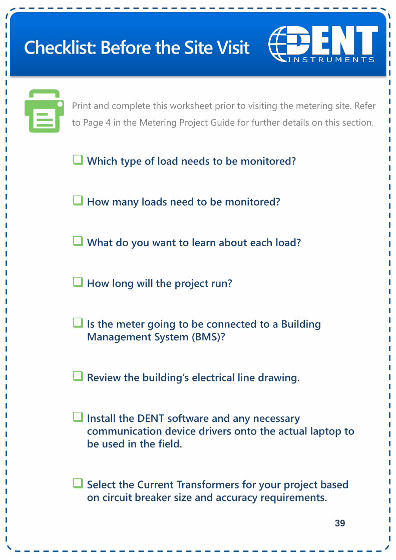
Which type of load needs to be monitored?
How many loads need to be monitored?
What do you want to learn about each load?
How long will the project run?
Is the meter going to be connected to a Building
Management System (BMS)?
Review the building’s electrical line drawing.
Install the DENT software and any necessary
communication device drivers onto the actual laptop to
be used in the field.
Select the Current Transformers for your project based
on circuit breaker size and accuracy requirements.
Checklist: Before the Site Visit
Print and complete this worksheet prior to visiting the metering site. Refer
to Page 4 in the Metering Project Guide for further details on this section.
40
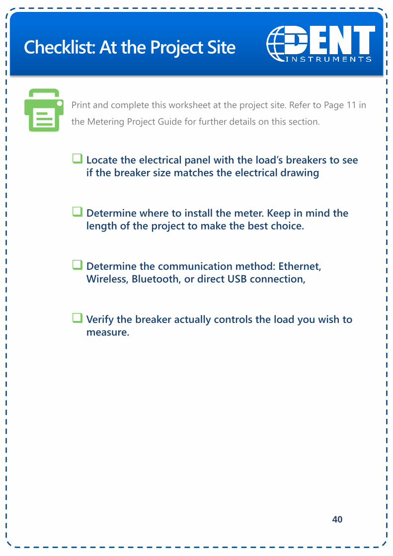
Locate the electrical panel with the load’s breakers to see
if the breaker size matches the electrical drawing
Determine where to install the meter. Keep in mind the
length of the project to make the best choice.
Determine the communication method: Ethernet,
Wireless, Bluetooth, or direct USB connection,
Verify the breaker actually controls the load you wish to
measure.
Checklist: At the Project Site
Print and complete this worksheet at the project site. Refer to Page 11 in
the Metering Project Guide for further details on this section.
41
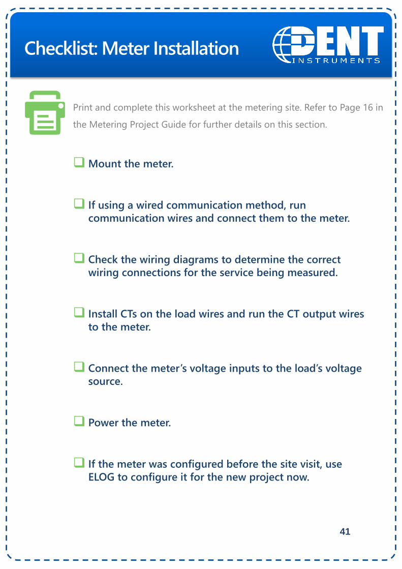
Mount the meter.
If using a wired communication method, run
communication wires and connect them to the meter.
Check the wiring diagrams to determine the correct
wiring connections for the service being measured.
Install CTs on the load wires and run the CT output wires
to the meter.
Connect the meter’s voltage inputs to the load’s voltage
source.
Power the meter.
If the meter was configured before the site visit, use
ELOG to configure it for the new project now.
Checklist: Meter Installation
Print and complete this worksheet at the metering site. Refer to Page 16 in
the Metering Project Guide for further details on this section.
42
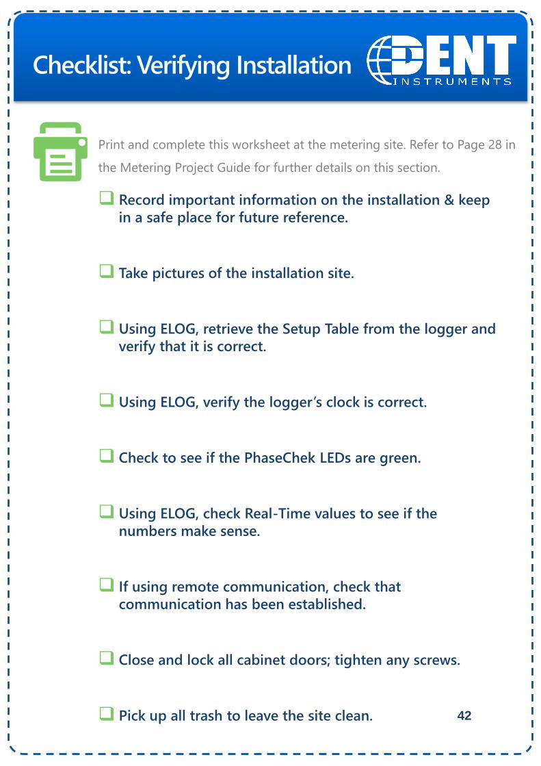
Record important information on the installation & keep
in a safe place for future reference.
Take pictures of the installation site.
Using ELOG, retrieve the Setup Table from the logger and
verify that it is correct.
Using ELOG, verify the logger’s clock is correct.
Check to see if the PhaseChek LEDs are green.
Using ELOG, check Real-Time values to see if the
numbers make sense.
If using remote communication, check that
communication has been established.
Close and lock all cabinet doors; tighten any screws.
Pick up all trash to leave the site clean.
Checklist: Verifying Installation
Print and complete this worksheet at the metering site. Refer to Page 28 in
the Metering Project Guide for further details on this section.
43
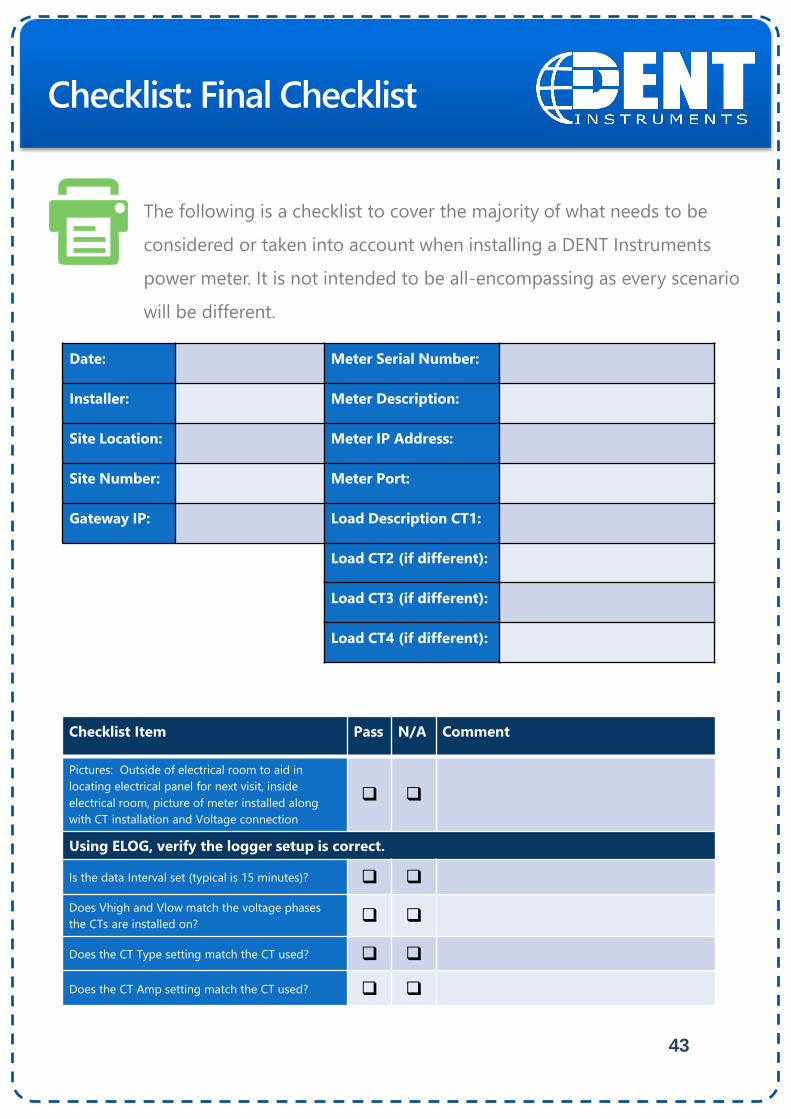
Checklist: Final Checklist
The following is a checklist to cover the majority of what needs to be
considered or taken into account when installing a DENT Instruments
power meter. It is not intended to be all-encompassing as every scenario
will be different.
Date: Meter Serial Number:
Installer: Meter Description:
Site Location: Meter IP Address:
Site Number: Meter Port:
Gateway IP: Load Description CT1:
Load CT2 (if different):
Load CT3 (if different):
Load CT4 (if different):
Checklist Item Pass N/A Comment
Pictures: Outside of electrical room to aid in
locating electrical panel for next visit, inside
electrical room, picture of meter installed along
with CT installation and Voltage connection
Using ELOG, verify the logger setup is correct.
Is the data Interval set (typical is 15 minutes)?
Does Vhigh and Vlow match the voltage phases
the CTs are installed on?
Does the CT Type setting match the CT used?
Does the CT Amp setting match the CT used?
44
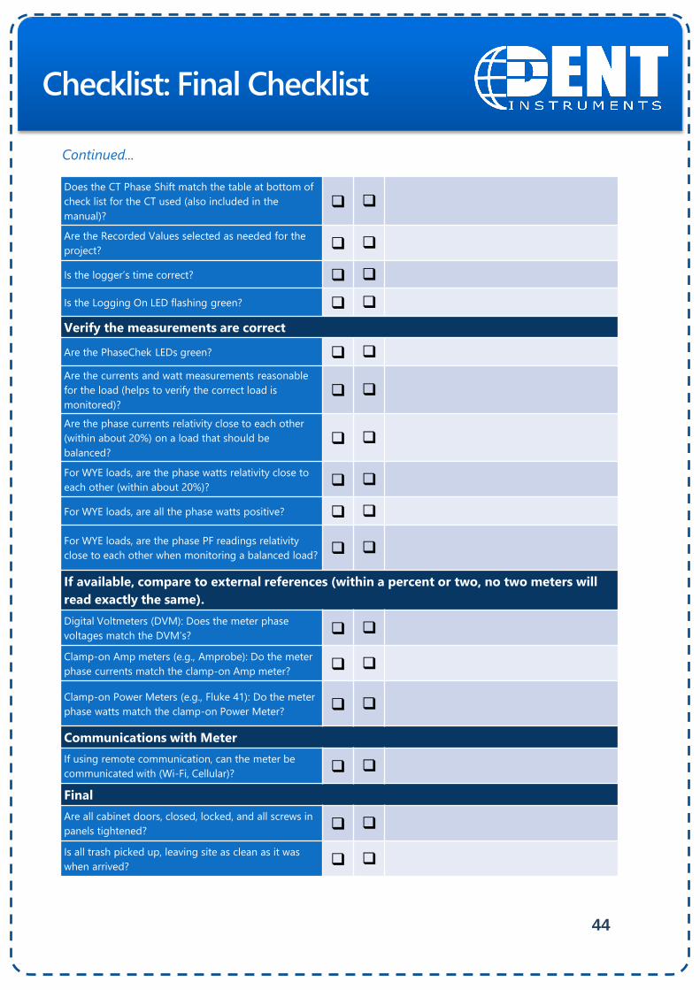
Checklist: Final Checklist
Does the CT Phase Shift match the table at bottom of
check list for the CT used (also included in the
manual)?
Are the Recorded Values selected as needed for the
project?
Is the logger’s time correct?
Is the Logging On LED flashing green?
Verify the measurements are correct
Are the PhaseChek LEDs green?
Are the currents and watt measurements reasonable
for the load (helps to verify the correct load is
monitored)?
Are the phase currents relativity close to each other
(within about 20%) on a load that should be
balanced?
For WYE loads, are the phase watts relativity close to
each other (within about 20%)?
For WYE loads, are all the phase watts positive?
For WYE loads, are the phase PF readings relativity
close to each other when monitoring a balanced load?
If available, compare to external references (within a percent or two, no two meters will
read exactly the same).
Digital Voltmeters (DVM): Does the meter phase
voltages match the DVM’s?
Clamp-on Amp meters (e.g., Amprobe): Do the meter
phase currents match the clamp-on Amp meter?
Clamp-on Power Meters (e.g., Fluke 41): Do the meter
phase watts match the clamp-on Power Meter?
Communications with Meter
If using remote communication, can the meter be
communicated with (Wi-Fi, Cellular)?
Final
Are all cabinet doors, closed, locked, and all screws in
panels tightened?
Is all trash picked up, leaving site as clean as it was
when arrived?
Continued...
45
Checklist: Final Checklist
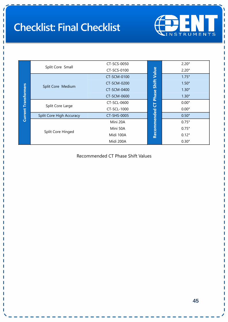
Recommended CT Phase Shift Values
Cu
rren
t T
ran
sfo
rmers
Split Core SmallCT-SCS-0050
Reco
mm
en
ded
CT
Ph
ase
Sh
ift
Valu
e
2.20°
CT-SCS-0100 2.20°
Split Core Medium
CT-SCM-0100 1.75°
CT-SCM-0200 1.50°
CT-SCM-0400 1.30°
CT-SCM-0600 1.30°
Split Core LargeCT-SCL-0600 0.00°
CT-SCL-1000 0.00°
Split Core High Accuracy CT‐SHS‐0005 0.50°
Split Core Hinged
Mini 20A 0.75°
Mini 50A 0.75°
Midi 100A 0.12°
Midi 200A 0.30°
46Metering Project Guide
DENT Instruments designs and manufactures data
loggers and energy recorders for today's energy
professionals. Our products are often the first step
in developing strong energy strategies, for
maintaining peak operations, and for lowering
operating costs. For over 25 years, our company
has built a reputation for providing instruments of
the highest quality whose robust design, small size
and remote data acquisition make them the
loggers of choice for companies large and small.
Since the company's emergence in 1988, we have
performed energy measurement studies for a
wide range of utility, government, and private
clients. This unique customer perspective has
strongly influenced the design of our products,
reflected in their ease of installation and use.
DENT Instruments is headquartered in Bend,
Oregon. We are proud to be a locally owned and
managed business, and a key contributor to the
economic health and well-being of Central
Oregon.
Energy & PowerMeasurement Solutions
© 2015 DENT Instruments, Inc. No portion of this document may be reproduced or
distributed without written permission from DENT Instruments.
johndobbie
Esis normal hor.