35
MQXF support structure An extension of LARP experience Helene Felice MQXF Design Review December 10 th to 12 th , 2014 CERN
| Date post: | 13-Dec-2015 |
| Category: |
Documents |
| Upload: | margery-jackson |
| View: | 214 times |
| Download: | 1 times |
MQXF support structureAn extension of LARP experience
Helene Felice
MQXF Design Review December 10th to 12th , 2014
CERN

LQLongQuadrupoleLQS01a-b/02/03
LRLong RacetrackLRS01-02
HQHigh-field QuadrupoleHQ01a-b-c-d-eHQ02a-b / HQ03a
Snapshot of LARP support structure experience
12/10/2014Helene Felice 2
Length
Time
2004
2014
2005
2006
2007
2008
2009
2010
2011
2012
2013
0.3 m 1 m 3.6-3.7 m
SQSubscale quad
TQTechnology QuadrupoleTQS01/02a-b-c/03a-b-c-d
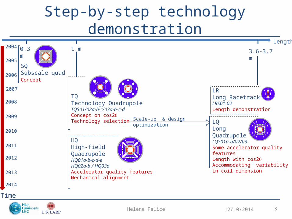
LRLong RacetrackLRS01-02Length demonstration
LQLongQuadrupoleLQS01a-b/02/03Some accelerator quality featuresLength with cos2qAccommodating variability in coil dimension
HQHigh-field QuadrupoleHQ01a-b-c-d-eHQ02a-b / HQ03aAccelerator quality featuresMechanical alignment
Step-by-step technology demonstration
12/10/2014Helene Felice 3
Length
Time
2004
2014
2005
2006
2007
2008
2009
2010
2011
2012
2013
0.3 m 1 m 3.6-3.7 m
SQSubscale quadConcept
TQTechnology QuadrupoleTQS01/02a-b-c/03a-b-c-dConcept on cos2qTechnology selection Scale-up & design optimization
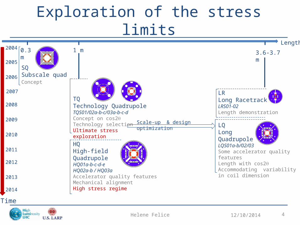
LRLong RacetrackLRS01-02Length demonstration
LQLongQuadrupoleLQS01a-b/02/03Some accelerator quality featuresLength with cos2qAccommodating variability in coil dimension
HQHigh-field QuadrupoleHQ01a-b-c-d-eHQ02a-b / HQ03aAccelerator quality featuresMechanical alignmentHigh stress regime
Exploration of the stress limits
12/10/2014Helene Felice 4
Length
Time
2004
2014
2005
2006
2007
2008
2009
2010
2011
2012
2013
0.3 m 1 m 3.6-3.7 m
SQSubscale quadConcept
TQTechnology QuadrupoleTQS01/02a-b-c/03a-b-c-dConcept on cos2qTechnology selectionUltimate stress exploration
Scale-up & design optimization
Outline
• Shell-based support structure concept• Exploring the limits
– TQ high stress • Step-by-step technology demonstration
– Design optimization– Length
• QXF support structure– Main features
12/10/2014Helene Felice 5
Helene Felice 6
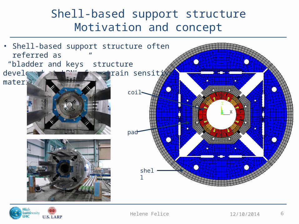
Shell-based support structureMotivation and concept
12/10/2014
• Shell-based support structure often referred as “bladder and keys” structuredeveloped at LBNL for strain sensitive material
coil
pad
shell
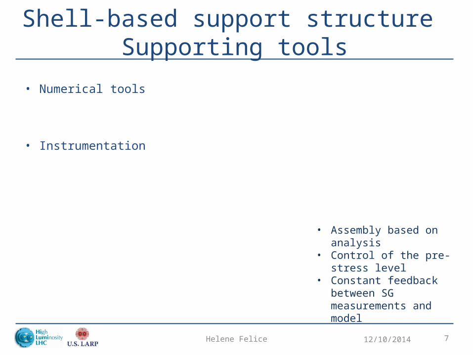
Shell-based support structure Supporting tools
12/10/2014Helene Felice 7
• Numerical tools
• Instrumentation
• Assembly based on analysis• Control of the pre-stress level• Constant feedback between
SG measurements and model
Helene Felice 8
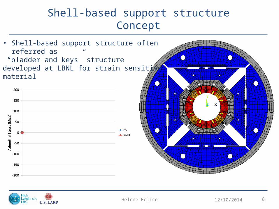
Shell-based support structureConcept
12/10/2014
• Shell-based support structure often referred as “bladder and keys” structuredeveloped at LBNL for strain sensitive material
Helene Felice 9
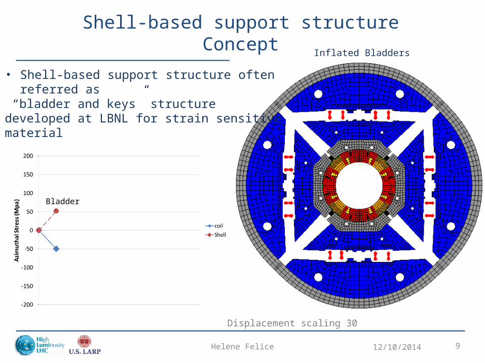
Shell-based support structureConcept
12/10/2014
Displacement scaling 30
• Shell-based support structure often referred as “bladder and keys” structuredeveloped at LBNL for strain sensitive material
Inflated Bladders
Bladder
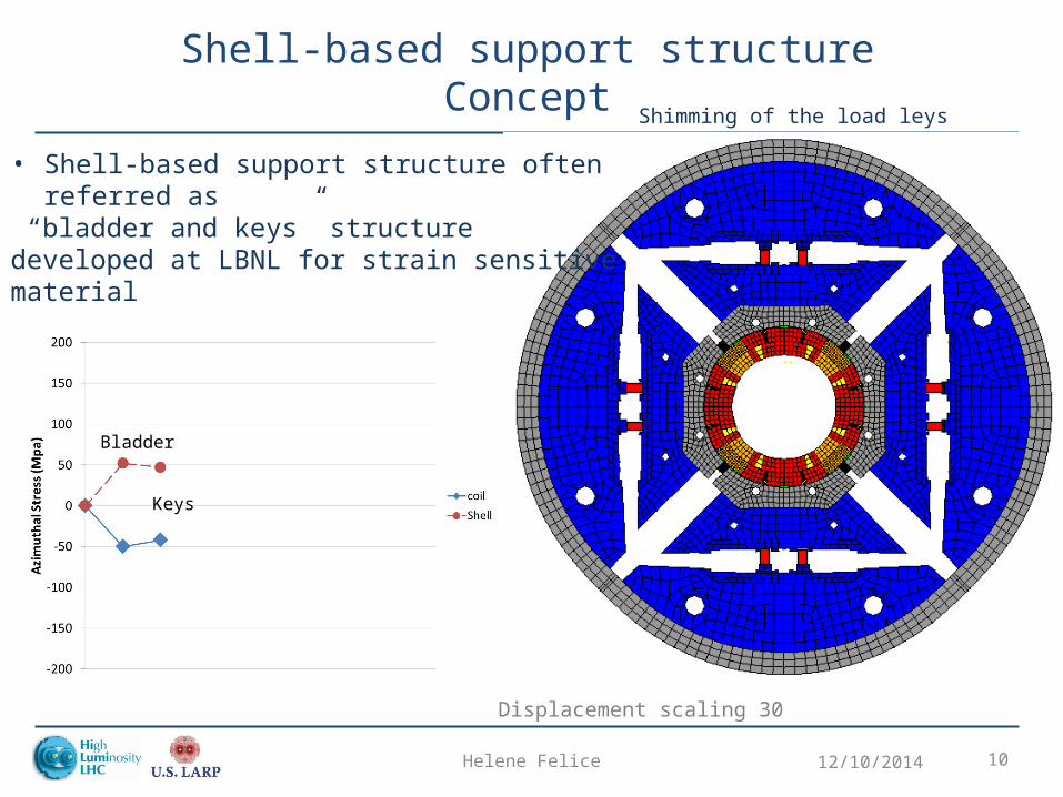
Helene Felice 10
Shell-based support structureConcept
12/10/2014
• Shell-based support structure often referred as “bladder and keys” structuredeveloped at LBNL for strain sensitive material
Displacement scaling 30
Shimming of the load leys
Keys
Bladder
Helene Felice 11
Shell-based support structureConcept
12/10/2014
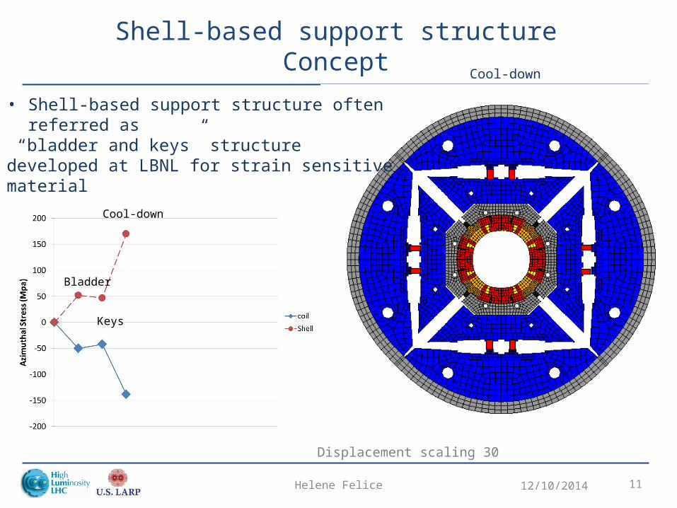
• Shell-based support structure often referred as “bladder and keys” structuredeveloped at LBNL for strain sensitive material
Displacement scaling 30
Cool-down
Cool-down
Keys
Bladder
Helene Felice 12
Shell-based support structureConcept
12/10/2014
Displacement scaling 30
Energized
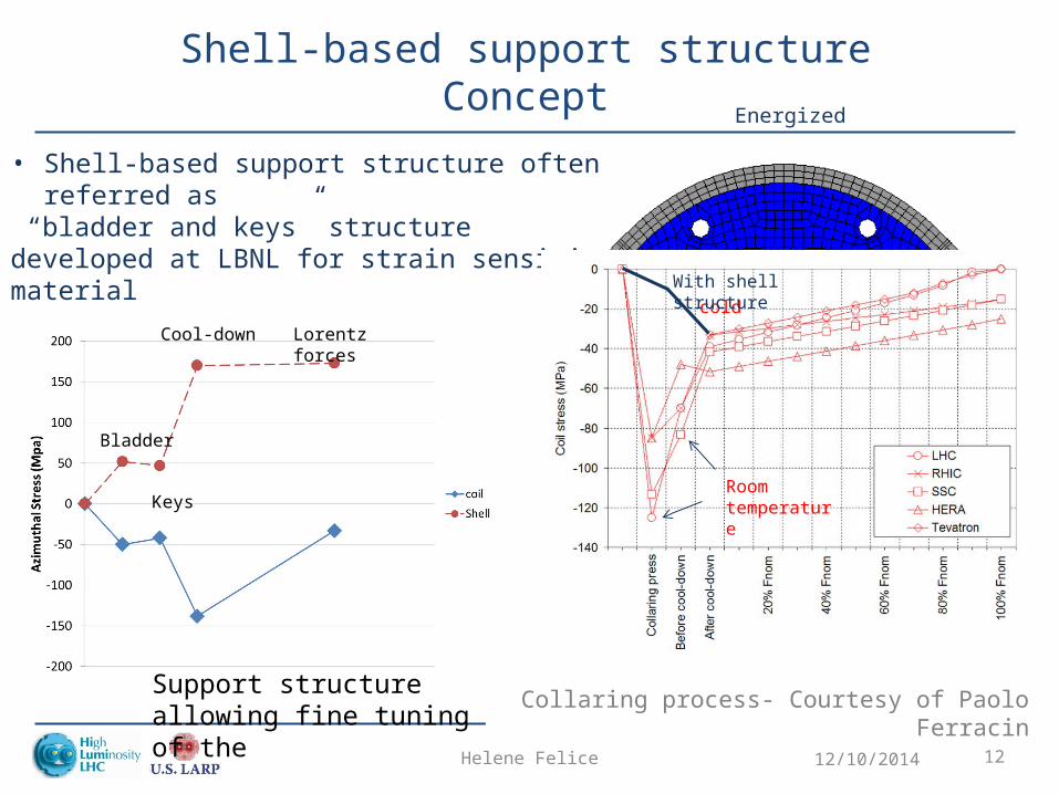
• Shell-based support structure often referred as “bladder and keys” structuredeveloped at LBNL for strain sensitive material
Lorentz forces
Cool-down
Keys
Bladder
cold
Room temperature
Collaring process- Courtesy of Paolo Ferracin
With shell structure
Support structure allowing fine tuning of the
Shell-based support structureKey features
• Gradual application of the preload: no overshoot
• Tunable preload– During assembly– In between tests
• Reversible assembly process– Allowing replacement of a defective coil if needed
• Correlation between models and strain gauges measurements
12/10/2014Helene Felice 13
Outline
• Shell-based support structure concept• Exploring the limits
– TQ high stress • Step-by-step technology demonstration
– Design optimization– Length
• QXF support structure– Main features
12/10/2014Helene Felice 14
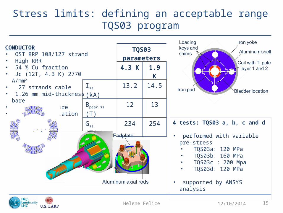
Stress limits: defining an acceptable rangeTQS03 program
12/10/2014Helene Felice 15
CONDUCTOR• OST RRP 108/127 strand• High RRR• 54 % Cu fraction• Jc (12T, 4.3 K) 2770 A/mm2
• 27 strands cable• 1.26 mm mid-thickness bare• 10 mm width bare• 0.125 mm insulation
TQS03parameters
4.3 K 1.9 K
Iss (kA) 13.2 14.5
Bpeak ss (T) 12 13
Gss (T/m) 234 254
4 tests: TQS03 a, b, c and d
• performed with variable pre-stress• TQS03a: 120 MPa• TQS03b: 160 MPa• TQS03c : 200 Mpa• TQS03d: 120 MPa
• supported by ANSYS analysis
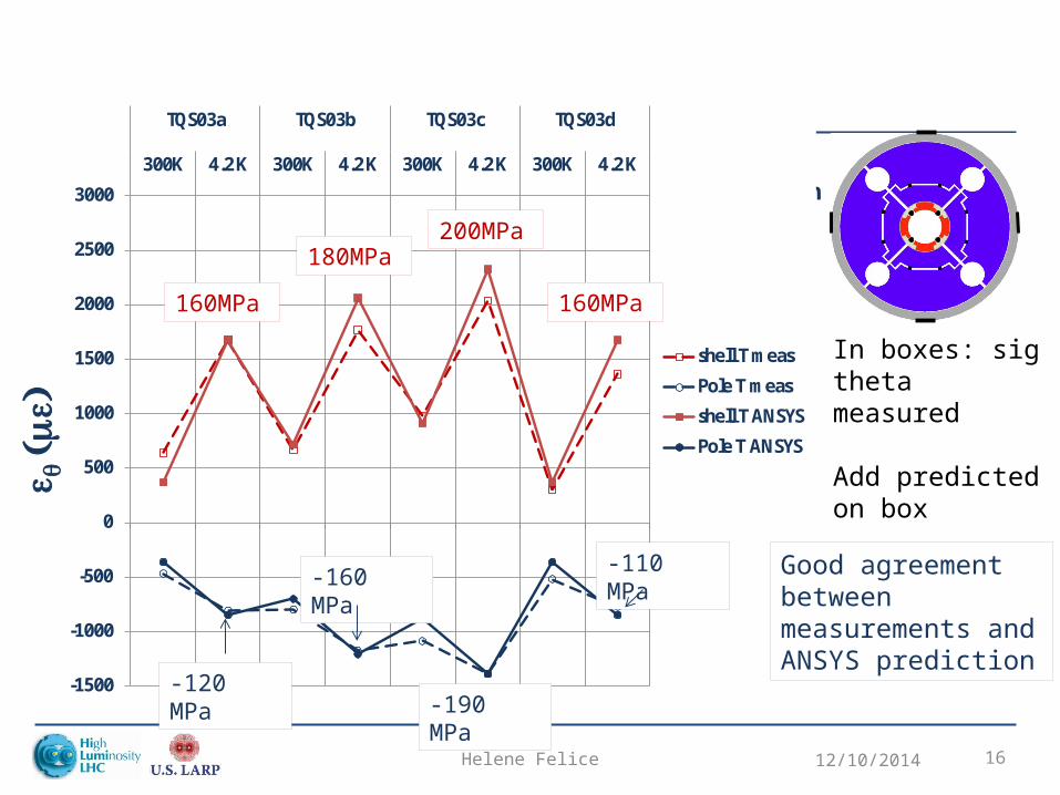
12/10/2014Helene Felice 16
Strain gauges location
In boxes: sig theta measured
Add predicted on box
-1500
-1000
-500
0
500
1000
1500
2000
2500
3000
300K 4.2 K 300K 4.2 K 300K 4.2 K 300K 4.2 K
TQS03a TQS03b TQS03c TQS03d
e q(me)
shell T meas
Pole T meas
shell T ANSYS
Pole T ANSYS
-160 MPa
-120 MPa-190 MPa
-110 MPa
200MPa180MPa
160MPa 160MPa
Good agreement between measurements and ANSYS prediction
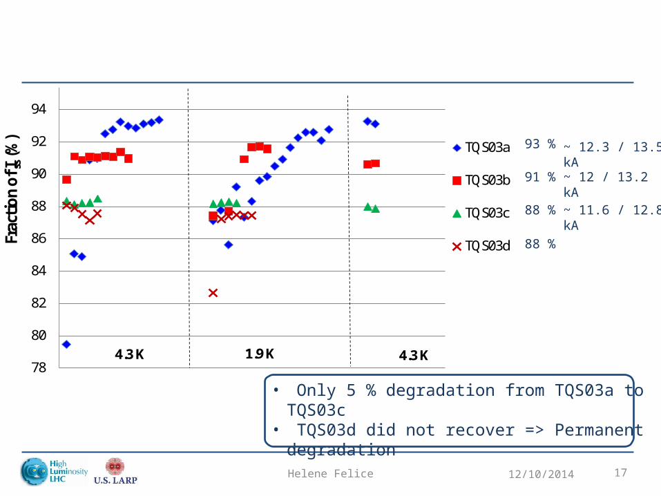
12/10/2014Helene Felice 17
78
80
82
84
86
88
90
92
94
96
98
100Fr
acti
on o
f I ss(%
)
TQS03a
TQS03b
TQS03c
TQS03d
4.3 K 1.9 K 4.3 K
93 %
91 %
88 %
88 %
~ 11.6 / 12.8 kA
• Only 5 % degradation from TQS03a to TQS03c• TQS03d did not recover => Permanent
degradation
~ 12 / 13.2 kA
~ 12.3 / 13.5 kA
Helene Felice 18
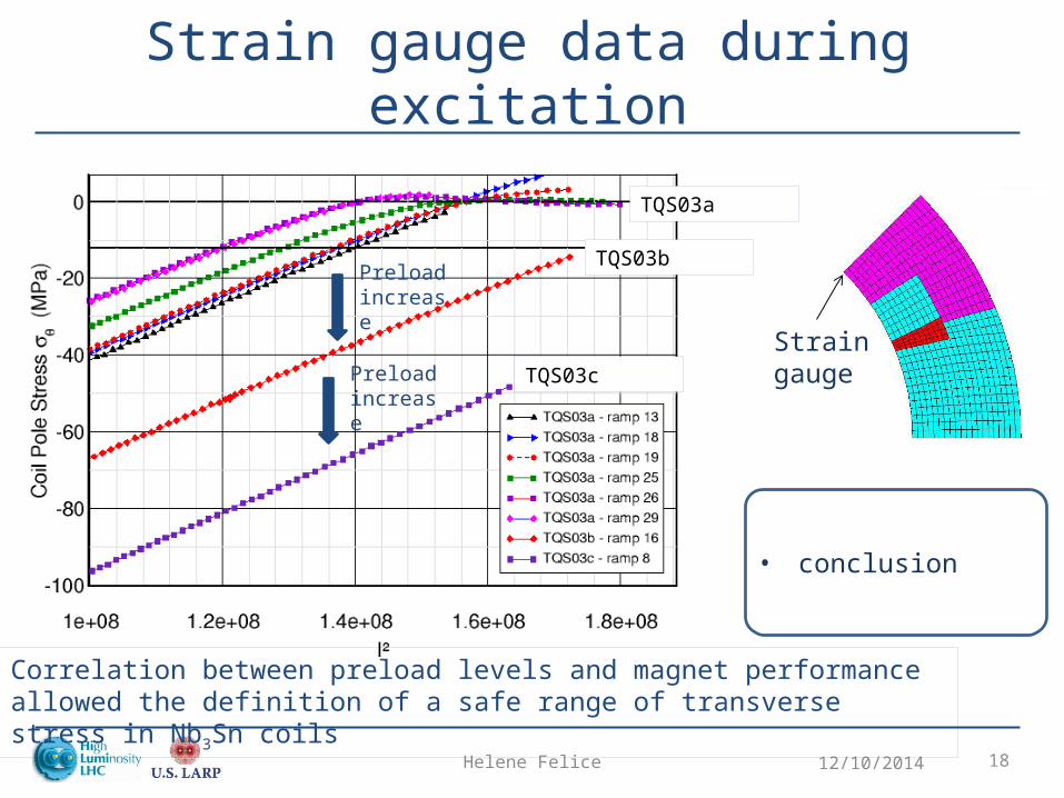
Strain gauge data during excitation
12/10/2014
Strain gauge
• conclusion
TQS03a
TQS03b
TQS03cPreload increase
Preload increase
Correlation between preload levels and magnet performance allowed the definition of a safe range of transverse stress in Nb3Sn coils
Outline
• Shell-based support structure concept• Exploring the limits
– TQ high stress • Step-by-step technology demonstration
– Design optimization– Length
• QXF support structure– Main features
12/10/2014Helene Felice 19
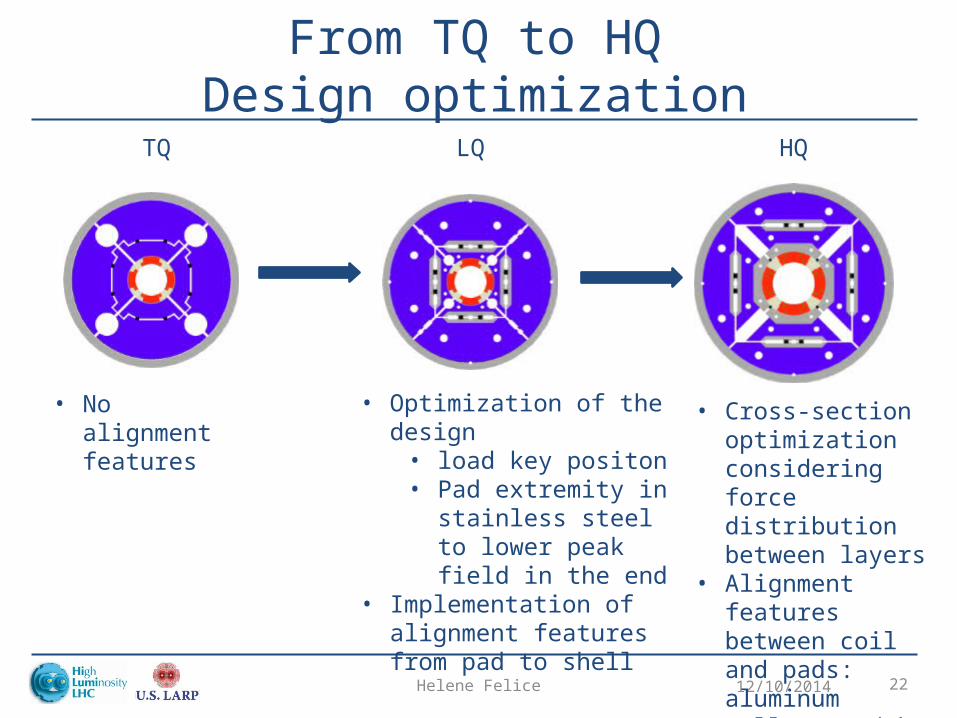
From TQ to HQDesign optimization
12/10/2014Helene Felice 20
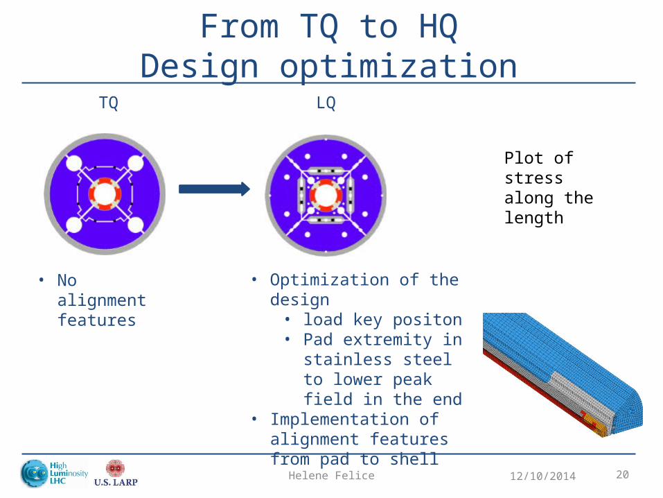
TQ LQ
• No alignment features
Plot of stress along the length
• Optimization of the design• load key positon• Pad extremity in
stainless steel to lower peak field in the end
• Implementation of alignment features from pad to shell
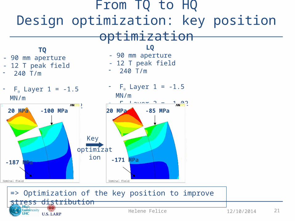
From TQ to HQDesign optimization: key position optimization
12/10/2014Helene Felice 21
TQ - 90 mm aperture- 12 T peak field - 240 T/m
- Fq Layer 1 = -1.5 MN/m- Fq Layer 2 = -1.02 MN/m
LQ- 90 mm aperture- 12 T peak field - 240 T/m
- Fq Layer 1 = -1.5 MN/m- Fq Layer 2 = -1.02 MN/m
-100 MPa
-187 MPa
-85 MPa
-171 MPa
Key
optimization
=> Optimization of the key position to improve stress distribution
20 MPa 20 MPa
From TQ to HQDesign optimization
12/10/2014Helene Felice 22
TQ LQ HQ
• No alignment features
• Cross-section optimization considering force distribution between layers
• Alignment features between coil and pads: aluminum collars and key
• Optimization of the design• load key positon• Pad extremity in
stainless steel to lower peak field in the end
• Implementation of alignment features from pad to shell
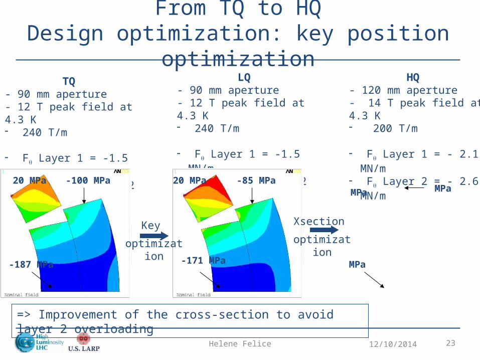
From TQ to HQDesign optimization: key position optimization
12/10/2014Helene Felice 23
TQ - 90 mm aperture- 12 T peak field at 4.3 K- 240 T/m
- Fq Layer 1 = -1.5 MN/m- Fq Layer 2 = -1.02 MN/m
LQ- 90 mm aperture- 12 T peak field at 4.3 K- 240 T/m
- Fq Layer 1 = -1.5 MN/m- Fq Layer 2 = -1.02 MN/m
HQ - 120 mm aperture- 14 T peak field at 4.3 K- 200 T/m
- Fq Layer 1 = - 2.1 MN/m- Fq Layer 2 = - 2.6 MN/m
-100 MPa
-187 MPa
-85 MPa
-171 MPa
MPa
MPa
Xsection
optimizationKey
optimization
=> Improvement of the cross-section to avoid layer 2 overloading
20 MPa 20 MPa MPa
12/10/2014Helene Felice 24
Stress in HQ
12/10/2014Helene Felice 25
Adresses:- Stress distribution
- 2D and 3D- Pad ss and iron- Ground for MQXF stress level
Outline
• Shell-based support structure concept• Exploring the limits
– TQ high stress • Step-by-step technology demonstration
– Design Optimization– Length
• QXF support structure– Main features
12/10/2014Helene Felice 26
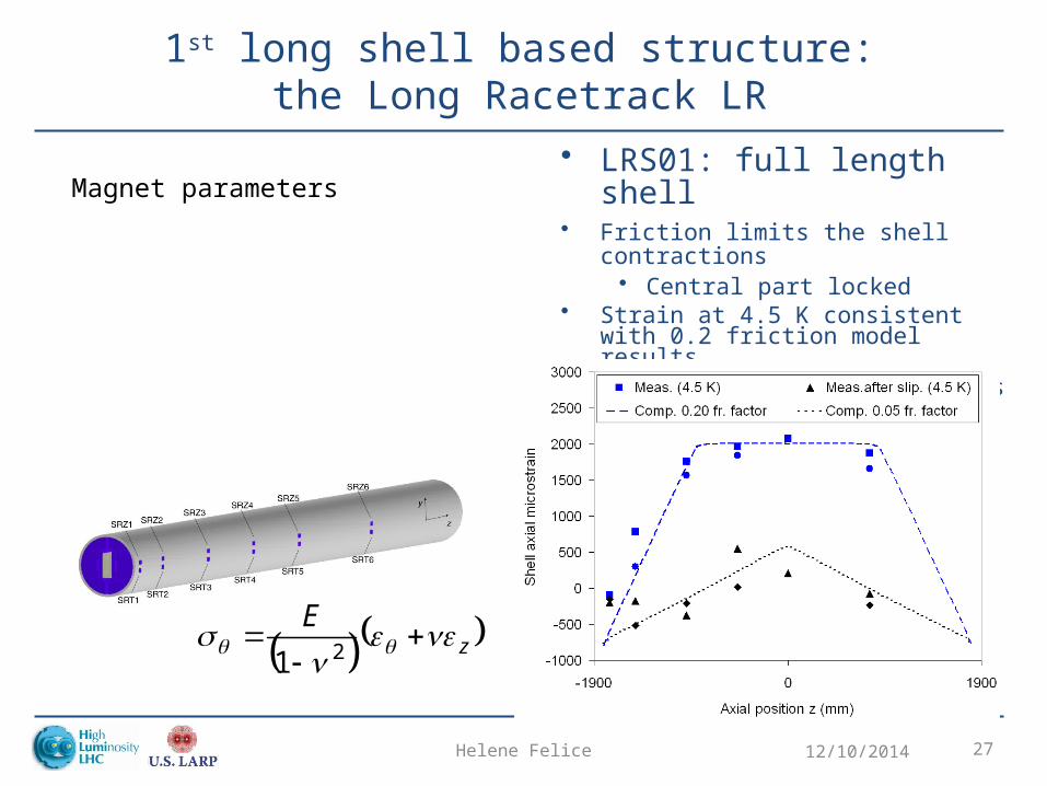
1st long shell based structure:the Long Racetrack LR
12/10/2014Helene Felice 27
• LRS01: full length shell• Friction limits the shell contractions
• Central part locked• Strain at 4.5 K consistent with 0.2 friction
model results• During excitation e.m. forces induced
slippage
Magnet parameters
( )( )zE ee
21
Helene Felice
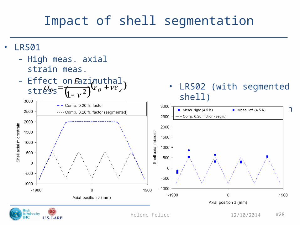
Impact of shell segmentation
12/10/2014 #28
• LRS01– High meas. axial strain meas.– Effect on azimuthal stress
• LRS02 (with segmented shell) – Reduced axial strain
LRS
LQS
LRS01
LRS02
( )( )zE ee
21
Helene Felice 29
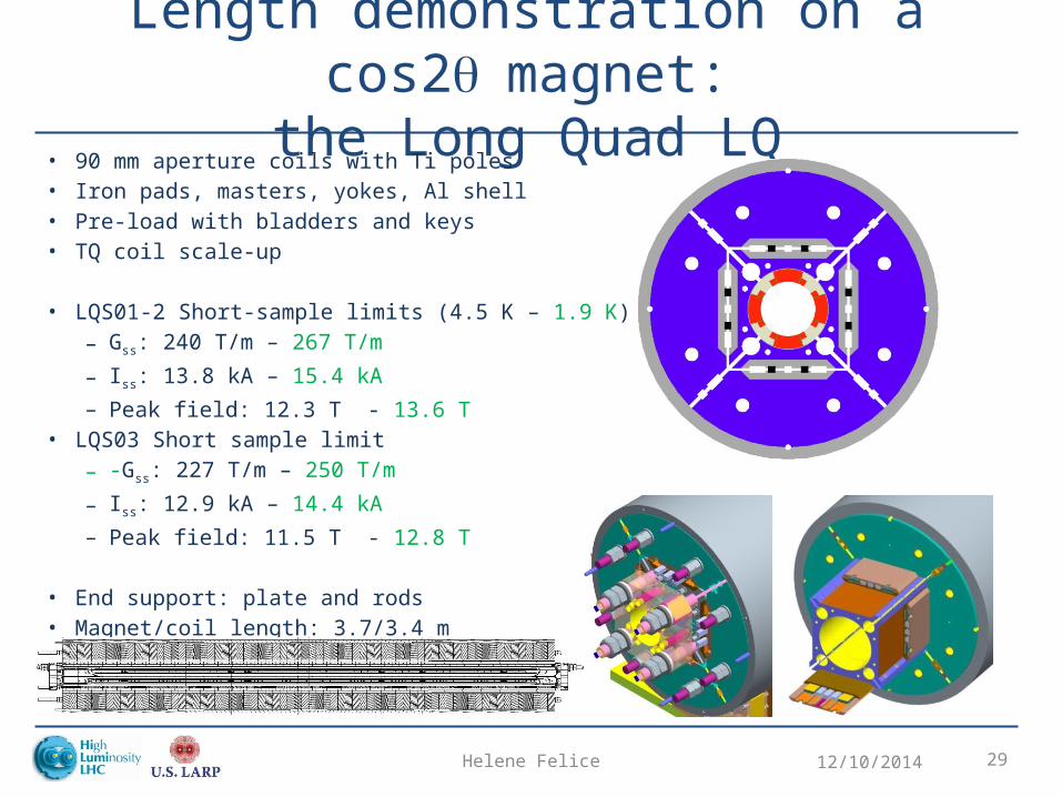
Length demonstration on a cos2 q magnet:the Long Quad LQ
12/10/2014
• 90 mm aperture coils with Ti poles • Iron pads, masters, yokes, Al shell• Pre-load with bladders and keys• TQ coil scale-up
• LQS01-2 Short-sample limits (4.5 K – 1.9 K)– Gss: 240 T/m – 267 T/m
– Iss: 13.8 kA – 15.4 kA– Peak field: 12.3 T - 13.6 T
• LQS03 Short sample limit
– -Gss: 227 T/m – 250 T/m
– Iss: 12.9 kA – 14.4 kA
– Peak field: 11.5 T - 12.8 T
• End support: plate and rods• Magnet/coil length: 3.7/3.4 m
30
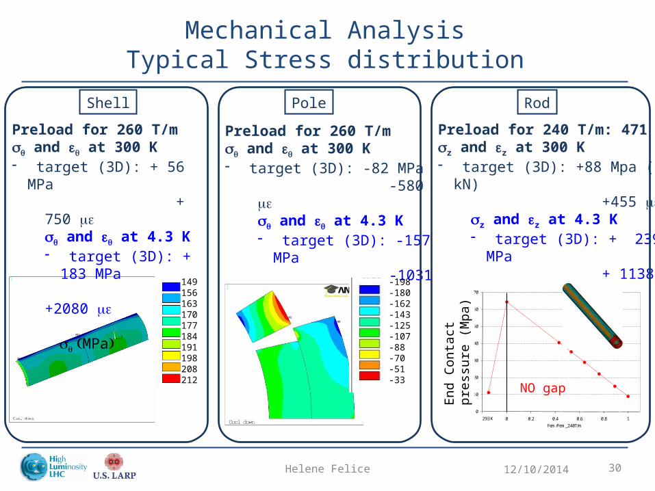
Preload for 240 T/m: 471 kNsz and ez at 300 K- target (3D): +88 Mpa (178 kN)
+455 mesz and ez at 4.3 K- target (3D): + 239 MPa + 1138 me
Rod
0
10
20
30
40
50
60
70
-0.2 0 0.2 0.4 0.6 0.8 1
End
cont
act p
ress
ure
(MPa
)
Fem/Fem_240T/m
293 K
End
Con
tact
pr
essu
re (
Mpa
)
Preload for 260 T/msq and eq at 300 K - target (3D): -82 MPa
-580 mesq and eq at 4.3 K - target (3D): -157 MPa -1031 me
s q (MPa)
Pole
Mechanical AnalysisTypical Stress distribution
12/10/2014Helene Felice
Preload for 260 T/msq and eq at 300 K- target (3D): + 56 MPa
+ 750 mesq and eq at 4.3 K- target (3D): + 183 MPa +2080 me
s q (MPa)
Shell
NO gap
-198-180-162-143-125-107-88-70-51-33
149156163170177184191198208212
Axial strain in shell
12/10/2014Helene Felice 31
Helene Felice 32
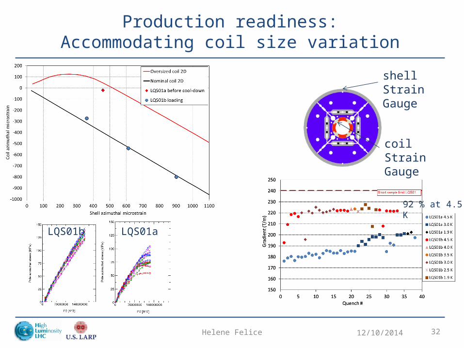
Production readiness:Accommodating coil size variation
12/10/2014
Expected
measured
shell Strain Gauge
coil Strain Gauge
Nominal
padPole StrainGauge
LQS01a
Nominal Oversized
padPole StrainGauge
92 % at 4.5 K
LQS01aLQS01b
Outline
• Shell-based support structure concept• Exploring the limits
– TQ high stress • Step-by-step technology demonstration
– Alignment features– Length
• QXF support structure– Main features
12/10/2014Helene Felice 33
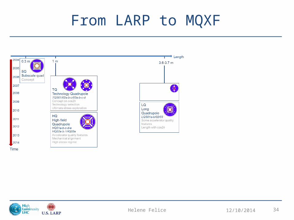
From LARP to MQXF
12/10/2014Helene Felice 34
MQXF support structure overview
12/10/2014Helene Felice 35
• Show how the key features described before are found in MQXF support structure design
• Point to Mariusz’s talk


